JP2010143520A - On-board display system and display method - Google Patents
On-board display system and display method Download PDFInfo
- Publication number
- JP2010143520A JP2010143520A JP2008325550A JP2008325550A JP2010143520A JP 2010143520 A JP2010143520 A JP 2010143520A JP 2008325550 A JP2008325550 A JP 2008325550A JP 2008325550 A JP2008325550 A JP 2008325550A JP 2010143520 A JP2010143520 A JP 2010143520A
- Authority
- JP
- Japan
- Prior art keywords
- vehicle
- image
- width
- display system
- virtual
- Prior art date
- Legal status (The legal status is an assumption and is not a legal conclusion. Google has not performed a legal analysis and makes no representation as to the accuracy of the status listed.)
- Abandoned
Links
Images

Classifications
-
- G—PHYSICS
- G02—OPTICS
- G02B—OPTICAL ELEMENTS, SYSTEMS OR APPARATUS
- G02B27/00—Optical systems or apparatus not provided for by any of the groups G02B1/00 - G02B26/00, G02B30/00
- G02B27/01—Head-up displays
-
- G—PHYSICS
- G01—MEASURING; TESTING
- G01C—MEASURING DISTANCES, LEVELS OR BEARINGS; SURVEYING; NAVIGATION; GYROSCOPIC INSTRUMENTS; PHOTOGRAMMETRY OR VIDEOGRAMMETRY
- G01C21/00—Navigation; Navigational instruments not provided for in groups G01C1/00 - G01C19/00
- G01C21/26—Navigation; Navigational instruments not provided for in groups G01C1/00 - G01C19/00 specially adapted for navigation in a road network
- G01C21/34—Route searching; Route guidance
- G01C21/36—Input/output arrangements for on-board computers
- G01C21/3626—Details of the output of route guidance instructions
- G01C21/365—Guidance using head up displays or projectors, e.g. virtual vehicles or arrows projected on the windscreen or on the road itself
-
- G—PHYSICS
- G02—OPTICS
- G02B—OPTICAL ELEMENTS, SYSTEMS OR APPARATUS
- G02B27/00—Optical systems or apparatus not provided for by any of the groups G02B1/00 - G02B26/00, G02B30/00
- G02B27/01—Head-up displays
- G02B27/0101—Head-up displays characterised by optical features
- G02B2027/0118—Head-up displays characterised by optical features comprising devices for improving the contrast of the display / brillance control visibility
- G02B2027/012—Head-up displays characterised by optical features comprising devices for improving the contrast of the display / brillance control visibility comprising devices for attenuating parasitic image effects
-
- G—PHYSICS
- G02—OPTICS
- G02B—OPTICAL ELEMENTS, SYSTEMS OR APPARATUS
- G02B27/00—Optical systems or apparatus not provided for by any of the groups G02B1/00 - G02B26/00, G02B30/00
- G02B27/01—Head-up displays
- G02B27/0101—Head-up displays characterised by optical features
- G02B2027/0129—Head-up displays characterised by optical features comprising devices for correcting parallax
-
- G—PHYSICS
- G02—OPTICS
- G02B—OPTICAL ELEMENTS, SYSTEMS OR APPARATUS
- G02B27/00—Optical systems or apparatus not provided for by any of the groups G02B1/00 - G02B26/00, G02B30/00
- G02B27/01—Head-up displays
- G02B27/0101—Head-up displays characterised by optical features
- G02B2027/0138—Head-up displays characterised by optical features comprising image capture systems, e.g. camera
-
- G—PHYSICS
- G02—OPTICS
- G02B—OPTICAL ELEMENTS, SYSTEMS OR APPARATUS
- G02B27/00—Optical systems or apparatus not provided for by any of the groups G02B1/00 - G02B26/00, G02B30/00
- G02B27/01—Head-up displays
- G02B27/0179—Display position adjusting means not related to the information to be displayed
- G02B2027/0187—Display position adjusting means not related to the information to be displayed slaved to motion of at least a part of the body of the user, e.g. head, eye
Landscapes
- Physics & Mathematics (AREA)
- Remote Sensing (AREA)
- Engineering & Computer Science (AREA)
- Radar, Positioning & Navigation (AREA)
- General Physics & Mathematics (AREA)
- Optics & Photonics (AREA)
- Automation & Control Theory (AREA)
- Instrument Panels (AREA)
- Processing Or Creating Images (AREA)
- Image Processing (AREA)
- Traffic Control Systems (AREA)
- Image Analysis (AREA)
- Fittings On The Vehicle Exterior For Carrying Loads, And Devices For Holding Or Mounting Articles (AREA)
- Controls And Circuits For Display Device (AREA)
Abstract
【課題】仮想先行車両像等の表示を任意の奥行き位置に高い位置精度で知覚させる単眼視の車載用表示システム及び表示方法を提供する。
【解決手段】車両の進路前方に関する情報である前方情報を取得する前方情報取得部と、前記車両に搭乗する観視者の片目の位置を検出する位置検出部と、前記前方情報取得部によって取得された前方情報に基づいて、前記車両の幅及び高さの少なくともいずれかに対応した大きさを有する第1仮想画像を、前記進路前方の景色内の対応する位置に生成し、前記生成した前記第1仮想画像を有する映像を含む光束を、前記検出された前記片目の位置に基づいて前記観視者の前記片目に向けて投影する映像投影部と、を備えたことを特徴とする車載用表示システムが提供される。
【選択図】図1The present invention provides a monocular on-vehicle display system and a display method for perceiving display of a virtual leading vehicle image or the like at an arbitrary depth position with high positional accuracy.
The information is acquired by a front information acquisition unit that acquires front information, which is information related to the forward direction of the vehicle, a position detection unit that detects the position of one eye of a viewer on the vehicle, and the front information acquisition unit. Based on the forward information, a first virtual image having a size corresponding to at least one of the width and height of the vehicle is generated at a corresponding position in the scenery ahead of the course, and the generated A vehicle-mounted image projection unit that projects a light beam including an image having a first virtual image toward the one eye of the viewer based on the detected position of the one eye; A display system is provided.
[Selection] Figure 1
Description
本発明は、車載用表示システム及び表示方法に関する。 The present invention relates to an in-vehicle display system and a display method.
車載用の表示装置として、車両の速度等の運行情報や目的地へのナビゲーション情報などの車両情報をフロントガラスに投影して、外界情報と車両情報とを同時に視認可能とするヘッドアップディスプレイHUD(Head-Up Display)が開発されている。 As a vehicle-mounted display device, a head-up display HUD that projects vehicle information such as operation information such as vehicle speed and navigation information to a destination onto a windshield so that external information and vehicle information can be viewed simultaneously. Head-Up Display) has been developed.
HUDは、見るヒトに対して直感的な表示の呈示が可能であり、運転者が観察する背景にマッチさせて経路表示などの情報の表示を行うことができる。このHUDにおいて、例えば仮想車等の画像を表示して、走行支援を行う技術が提案されている。 The HUD can present an intuitive display to the person who sees it, and can display information such as a route display in accordance with the background observed by the driver. In this HUD, for example, a technique has been proposed in which an image of a virtual vehicle or the like is displayed and driving support is provided.
例えば、特許文献1には、前方の道路状況と自車両の走行状態とに基づき、仮想先行車の表示を制御するHUDが開示されている。この仮想先行車により自車両の前方の障害物やカーブといった道路状況に関する情報を違和感なく適度に運転者に伝え、道路状況に応じた運転操作を可能としようとするものである。
For example,
また、例えば、特許文献2には、所定幅よりも狭い道に入ったときには自車両の車幅情報の表示を開始し、広い道に入ったときにはその表示を自動的に終了するHUDが開示されている。この場合、HUDは、自車両の車幅情報として、タイヤの軌跡や架空の車両等を表示したり、また、対向車と接触するかどうかを検出し、その表示を行うことが提案されている。 For example, Patent Document 2 discloses a HUD that starts displaying the vehicle width information of the host vehicle when entering a road narrower than a predetermined width and automatically ends the display when entering a wide road. ing. In this case, it is proposed that the HUD displays the tire trajectory, an imaginary vehicle, or the like as the vehicle width information of the own vehicle, or detects whether or not the vehicle is in contact with the oncoming vehicle and displays it. .
このように、HUDにおいて、自車両の幅などに対応した仮想先行車等の印を表示することによって、走行支援をすることができる。 As described above, in the HUD, it is possible to provide driving support by displaying a mark such as a virtual leading vehicle corresponding to the width of the host vehicle.
通常のHUDの場合、HUDの表示は両眼で観察される。HUDによって表示される虚像の奥行き位置は、光学的に設計された位置(光学的表示位置)であり、多くの場合、運転者から2〜3m先の位置に設定される。従って、両眼視のHUDの場合、運転者が運転中に遠方を見ながらHUDの表示を同時に見ようとすると、HUDの表示物は2重像となって認識されるため、非常に見にくい。逆に、HUDの表示を見ようとすると、両眼視差によって表示像は2〜3m先に認識されるために、背景の遠方を同時に認識することが困難である。
さらに、HUDの表示像はフロントガラスなどに反射させて観察されるので、フロントガラスの反射スクリーンの厚さに起因したパララックス(2重像)が発生し、これによっても表示が見難くなる。
In the case of a normal HUD, the display of the HUD is observed with both eyes. The depth position of the virtual image displayed by the HUD is an optically designed position (optical display position), and is often set to a position 2 to 3 m away from the driver. Therefore, in the case of HUD for binocular vision, if the driver tries to see the HUD display at the same time while looking far away during driving, the display object of the HUD is recognized as a double image, which is very difficult to see. On the other hand, when viewing the HUD display, the display image is recognized 2 to 3 meters ahead by binocular parallax, so it is difficult to simultaneously recognize the distant background.
Further, since the display image of the HUD is reflected on the windshield and the like, a parallax (double image) is generated due to the thickness of the reflection screen of the windshield, which also makes it difficult to see the display.
このように、両眼視差に起因した見難さを解決するために、片目で表示像を観察する単眼視HUDが提案されている。例えば、両眼視差をなくして、HUDによる表示物の奥行き位置を光学的表示位置よりも遠くに見せる目的で片目のみに表示像を提示する技術がある。
また、上記の2重像を防止する目的で、片目のみに表示像を呈示する技術が提案されている(例えば、特許文献3参照)。
Thus, in order to solve the difficulty in viewing due to binocular parallax, a monocular HUD for observing a display image with one eye has been proposed. For example, there is a technique in which a binocular parallax is eliminated and a display image is presented only to one eye for the purpose of making the depth position of the display object by HUD appear farther than the optical display position.
In addition, for the purpose of preventing the above-described double image, a technique for presenting a display image only to one eye has been proposed (see, for example, Patent Document 3).
しかしながら、単眼視HUDでは認識される奥行き位置は背景位置に大きく依存するため、認識される奥行き位置の誤差が大きくなる。従って、単眼視HUDにおいて、走行支援を行うための仮想先行車等を任意の奥行き位置に高い位置精度で知覚させるための新しい技術が必要である。
本発明は、仮想先行車両像等の表示を任意の奥行き位置に高い位置精度で知覚させる単眼視の車載用表示システム及び表示方法を提供する。 The present invention provides a monocular in-vehicle display system and a display method for perceiving display of a virtual leading vehicle image or the like at an arbitrary depth position with high positional accuracy.
本発明の一態様によれば、車両の進路前方に関する情報である前方情報を取得する前方情報取得部と、前記車両に搭乗する観視者の片目の位置を検出する位置検出部と、前記前方情報取得部によって取得された前方情報に基づいて、前記車両の幅及び高さの少なくともいずれかに対応した大きさを有する第1仮想画像を、前記進路前方の景色内の対応する位置に生成し、前記生成した前記第1仮想画像を有する映像を含む光束を、前記検出された前記片目の位置に基づいて前記観視者の前記片目に向けて投影する映像投影部と、を備えたことを特徴とする車載用表示システムが提供される。 According to one aspect of the present invention, a front information acquisition unit that acquires front information that is information related to the forward direction of the vehicle, a position detection unit that detects the position of one eye of a viewer who is on the vehicle, and the front Based on the forward information acquired by the information acquisition unit, a first virtual image having a size corresponding to at least one of the width and height of the vehicle is generated at a corresponding position in the scenery ahead of the course. And a video projection unit that projects a light beam including the generated video having the first virtual image toward the one eye of the viewer based on the detected position of the one eye. A featured in-vehicle display system is provided.
また、本発明の他の一態様によれば、車両の進路前方に関する情報である前方情報に基づいて、前記車両の幅及び高さの少なくともいずれかに対応した大きさを有する第1仮想画像を前記進路前方の景色内の対応する位置に生成し、前記生成した前記第1仮想画像を有する映像を含む光束を生成し、前記車両に搭乗する観視者の片目の位置を検出し、前記光束を前記検出された前記片目の位置に基づいて前記観視者の前記片目に向けて投影することを特徴とする表示方法が提供される。 According to another aspect of the present invention, the first virtual image having a size corresponding to at least one of the width and the height of the vehicle based on the forward information that is information related to the forward direction of the vehicle. The light beam is generated at a corresponding position in the scene in front of the course, the light beam including the generated image including the first virtual image is generated, the position of one eye of a viewer on the vehicle is detected, and the light beam is detected. Is projected toward the one eye of the viewer based on the detected position of the one eye.
本発明によれば、仮想先行車両像等の表示を任意の奥行き位置に高い位置精度で知覚させる単眼視の車載用表示システム及び表示方法が提供される。 ADVANTAGE OF THE INVENTION According to this invention, the vehicle-mounted display system and display method of the monocular vision which perceive the display of a virtual leading vehicle image etc. to arbitrary depth positions with high positional accuracy are provided.
以下、本発明の実施の形態について図面を参照して詳細に説明する。
なお、本願明細書と各図において、既出の図に関して前述したものと同様の要素には同一の符号を付して詳細な説明は適宜省略する。
Hereinafter, embodiments of the present invention will be described in detail with reference to the drawings.
Note that, in the present specification and each drawing, the same elements as those described above with reference to the previous drawings are denoted by the same reference numerals, and detailed description thereof is omitted as appropriate.
(第1の実施の形態)
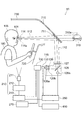
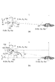
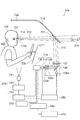
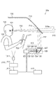
図1は、本発明の第1の実施形態に係る車載用表示システムの構成を例示する模式図である。
図1に表したように、本発明の第1の実施形態に係わる車載用表示システム10は、前方情報取得部410と位置検出部210と映像投影部115とを備える。
(First embodiment)
FIG. 1 is a schematic view illustrating the configuration of an in-vehicle display system according to the first embodiment of the invention.
As shown in FIG. 1, the in-
前方情報取得部410は、車両730の進路前方に関する情報である前方情報を取得する。
位置検出部210は、車両730に搭乗する観視者100の片目101の位置を検出する。
映像投影部115は、前方情報取得部410によって取得された前方情報に基づいて、前記前方情報に対応した位置において、車両730の幅及び高さの少なくともいずれかに対応する大きさを有する第1仮想像を、前記進路前方の景色内の対応する位置に生成し、前記生成した第1仮想画像を有する映像を含む光束112を、前記検出された片目101の位置に基づいて前記観視者100の片目101に向けて投影する。
The forward
The
Based on the forward information acquired by the forward
車両730は、例えば自動車などの車両であり、観視者100はその自動車を操縦する運転者(操縦者)である。すなわち、車両730は、本実施形態に係る車載用表示システム10が搭載される車両、すなわち、自車両である。
前方情報は、車両730の進路前方に関する情報であり、また、分岐点などがある場合においては車両730の進行すると推定される進路前方に関する情報であり、道路や交差点の形状等を含む情報である。
The
The forward information is information related to the forward direction of the
第1仮想画像は、車両730の幅及び高さの少なくともいずれかに対応する画像であり、例えば車両730を後方からみたときの形状を有する画像や、その画像を模式的に変形した画像や、さらには、車両730の幅及び高さを示す長方形などの図形などであり、各種の線であっても良い。以下では、第1仮想画像として、車両730に基づく仮想先行車両像を用いる場合として説明する。
The first virtual image is an image corresponding to at least one of the width and height of the
仮想先行車両像(第1仮想画像)が配置される前方情報内における位置の導出、及び、映像内における仮想先行車両像の配置の具体例に関しては後述する。 Specific examples of the derivation of the position in the front information where the virtual leading vehicle image (first virtual image) is arranged and the arrangement of the virtual leading vehicle image in the video will be described later.
同図に例示したように、車載用表示システム10は、例えば自動車等の車両730の中、すなわち、例えば、操縦者である観視者100からみて車両730のダッシュボード720の奥に設けられる。
そして、映像投影部115は、例えば、映像データ生成部130と、映像形成部110と、投影部120と、を有する。
As illustrated in the figure, the in-
The
映像データ生成部130は、前方情報取得部410で取得された前方情報と、観視者100の検出された片目101の位置と、に基づいて仮想先行車両像を含む映像に関するデータを生成する。
The video
そして、映像データ生成部130で生成された映像データを含む映像信号は、映像形成部110に供給される。
The video signal including the video data generated by the video
映像形成部110としては、例えば、液晶表示装置(LCD)やDMD(Digital Micromirror Device)、及び、MEMS(Micro-electro-mechanical System)等の各種光スイッチを用いることができる。そして、映像形成部110は、映像データ生成部130から供給された仮想先行車両像を有する映像データを含む映像信号に基づいて、映像形成部110の画面に映像を形成する。
映像形成部110には、レーザプロジェクタやLED(発光ダイオード)プロジェクタなどを用いることもでき、その場合は、レーザビームにより映像を形成する。
以下では、映像形成部110として、光源としてLEDを用いたLCDを用いた場合として説明する。なお、光源にLEDを用いることで装置を小型・省電力化できる。
As the
The
Hereinafter, the case where an LCD using an LED as a light source is used as the
そして、投影部120は、映像形成部110で形成された映像を観視者100の片目101に投影する。
Then, the projecting
投影部120には、例えば、投影レンズ、ミラー、及び、発散角(拡散角)を制御する各種の光学素子が用いられる。また、場合によっては、投影部120は光源を含む。
本具体例では、結像レンズ120a、発散角を制御するレンチキュラーレンズ120b、ミラー126及び非球面フレネルレンズ127が用いられている。
For the
In this specific example, an
そして、映像形成部110から出射した光束112は、結像レンズ120a、レンチキュラーレンズ120b、ミラー126及び非球面フレネルレンズ127を経て、車載用表示システム10が搭載される車両730の例えばフロントガラス710(ウインドシールド、透明板)に設けられる反射体711(半透明の反射体)により反射され、観視者100の片目101に投影される。そして観視者100は、反射体711を介して、虚像形成位置310aの位置に形成された虚像310を知覚する。このように、車載用表示システム10は、HUDとして使用できる。なお、この虚像310として、例えば、仮想先行車両像が用いられる。
The
このように、発散角が制御された光束112が観視者100に到達し、観視者100は片目101で映像を観視する。このとき、観視者100の両眼の間隔は平均6cmであるので、観視者100の頭部105上における光束112の幅を6cm程度に制御すると両眼に映像が投影されることがない。なお、映像の見易さから観視者100の優位眼に映像を投影することが好ましい。
なお、上記では、光束112の発散角を制御する手段としてレンチキュラーレンズ120bを用いたが、この他に、拡散角度を制御した拡散板などを用いることもできる。
In this way, the
In the above description, the
ミラー126は、駆動部126aによって角度調整ができるようにすることができる。ミラー126として、平面鏡以外に、パワーを持った反射面として、凹面ミラーを用いることができ、この場合も駆動部126aによって、その角度を変えることができる。なお、表示される映像においては、ミラー126の角度などに依存したひずみが発生することがあるが、これは映像データ生成部130において、ひずみ補正を行うことで、ひずみのない映像を観視者100に呈示することができる。
なお、映像投影部115は、上記の具体例の他に、後述するように各種の変形が可能である。
The angle of the
Note that the
一方、位置検出部210は、観視者100の映像が投影される片目101を検出する。位置検出部210は、例えば、観視者100を撮像する撮像部211と、撮像部211によって撮像された撮像画像を画像処理する画像処理部212と、画像処理部212で画像処理されたデータに基づいて、観視者100の片目101の位置を判断し、検出する演算部213と、を含むことができる。
On the other hand, the
演算部213においては、例えば、特許第3279913号公報などに記載されている人物認証に関する技術を用いて、観視者100の顔認識と顔部品としての眼球位置を算出し、観視者100の映像を投影する片目101の位置を判断して検出する。
The
なお、撮像部211は、例えば、車両730の運転席の前方や側方に配置され、例えば、操縦者である観視者100の顔面の像を撮像し、上記のように、観視者の片目101の位置を検出する。
The
また、本具体例では、車両730の走行状態や運転状態に関する情報を取得する車両情報取得部270がさらに設けられている。車両情報取得部270は、例えば、車両730の走行速度や連続して走行している時間やハンドル(操舵舵)等の操作頻度等の運転状態を検出することができる。そして、車両情報取得部270によって取得された車両730の運転状態に関するデータは、映像投影部115に供給される。具体的には、映像データ生成部130に供給される。後述するように、映像データ生成部130はこれに基づき、仮想先行車両像に関するデータの生成状態を制御することができる。ただし、車両情報取得部270は必要に応じて設けられれば良く、例えば、車両情報取得部270が取得する車両730に関する各種のデータは、車載用表示システム10の外部に設けられた部分によって取得され、それが映像データ生成部130に供給されても良い。
In this specific example, a vehicle
さらに、本具体例では、制御部250がさらに設けられている。制御部は、位置検出部210で検出された観視者100の片目101の位置に基づいて、映像投影部115を制御することにより、光束112の投影範囲114aと投影位置114の少なくともいずれかを調整する。
Furthermore, in this specific example, a
制御部250は、例えば、本具体例の場合、投影部120の一部を構成するミラー126に連結された駆動部126aを制御して、ミラー126の角度を制御することによって、投影位置114を制御する。
For example, in the case of this specific example, the
また、制御部250は、例えば、投影部120を構成する各種の光学部品を制御して、投影範囲114aを制御することができる。
Further, the
これにより、観視者100の頭部105が動いた際にも、それに追従して、映像の呈示位置を制御することが可能となり、観視者100の頭部105の移動による映像呈示位置からの外れがなくなり、実用的な観視範囲を広くすることが可能になる。
Thereby, even when the
なお、制御部250は、例えば、映像形成部110を制御して映像の輝度やコントラストなどを調整しても良い。
For example, the
なお、上記の具体例では、制御部250によって、検出された片目101の位置に基づいて光束112の投影範囲114aと投影位置114の少なくともいずれかを自動的に調整するが、本発明はこれに限らない。例えば、検出された片目101の位置に基づいて光束112の投影範囲114aと投影位置114の少なくともいずれかを手動で調整するようにしても良い。この場合は、例えば、投影部120によって撮像された観視者100の頭部105の画像を何らかのディスプレイで見ながら、駆動部126aを手動で制御して、ミラー126の角度を制御することができる。
In the above specific example, the
このように、本実施形態に係わる車載用表示システム10は、単眼視の表示システムである。そして、前方情報取得部410が設けられ、これにより、前記前方情報に対応する位置を有する仮想先行車両像を生成することができる。すなわち、後述するように、進路前方の道に対応させた所望の奥行き位置に仮想先行車両像を配置して生成できる。
そして、前記検出された片目の位置に基づいて前記観視者の片目に向けて投影する。これにより、仮想先行車両像を任意の奥行き位置に高い位置精度で知覚させ、運転者にとって見やすい表示を行う車載用表示システムが提供できる。
Thus, the vehicle-mounted
Then, projection is performed toward one eye of the viewer based on the detected position of one eye. Accordingly, it is possible to provide an in-vehicle display system that allows a virtual preceding vehicle image to be perceived at an arbitrary depth position with high positional accuracy and displays a display that is easy to see for the driver.
上記において、映像データ生成部130は、前方情報取得部410で取得された前方情報と、観視者100の検出された片目101の位置と、に基づいて仮想先行車両像を含む映像に関するデータを生成したが、片目101の位置が実質的に変動しない場合は、仮想先行車両像は、前方情報取得部410で取得された前方情報に基づいて生成しても良い。これによっても、任意の奥行き位置に仮想前方車両像を表示でき、運転者にとって見やすい表示を行う車載用表示システムが提供できる。
In the above, the video
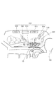
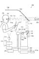
図2は、本発明の第1の実施形態に係る車載用表示システムの動作状態を例示する模式図である。
図2に表したように、本実施形態に係る車載用表示システム10においては、表示映像510として、少なくとも仮想先行車両像180が表示され、フロントガラス710の反射体711(図示せず)に投影して表示される。これにより、運転者(観視者)100は、外界映像520と表示映像510とを同時に見る。このように、車載用表示システム10は車載用のHUDとして用いられる。なお、表示映像510は、仮想先行車両像180以外に、例えば、現在位置511、周辺の建物情報等512、進路の表示矢印513、速度や燃料等の車両情報514等を含んでも良い。
FIG. 2 is a schematic view illustrating the operation state of the in-vehicle display system according to the first embodiment of the invention.
As shown in FIG. 2, in the in-
HUDは背景(外界映像520)に重畳した表示ができるため、運転者(観視者100)は直感的に表示を理解できることが利点である。特に、単眼視HUDは、運転者の注視点が遠くにあってもHUD表示も同時に見ることが可能であるので、外界に重畳させる表示に向いている。 Since the HUD can be displayed superimposed on the background (external video 520), it is advantageous that the driver (viewer 100) can intuitively understand the display. In particular, the monocular HUD is suitable for display superimposed on the outside world because the HUD display can be simultaneously seen even if the driver's point of interest is far away.
本実施形態に係る車載用表示システム10においては、仮想先行車両像180は、前方情報取得部410によって取得された前方情報に基づいて、前記前方情報に対応した位置に生成される。この時、前方情報取得部410によって取得された前方情報には、車両730の進行すると推定される道の通行可能な水平方向及び垂直方向の少なくともいずれかの幅が含まれる。
In the in-
ここで、車両730の進行すると推定される道とは、例えば車両730が現在進行しつつある道の進行方向の前方の道である。また、例えば、停止状態の車両730の車体の後方から前方に向かう方向の前方の道である。また、例えばナビゲートシステム等によって車両730の進行する経路(ルート)が定められる場合などは、その経路に基づく進路前方の道である。さらに、「道」は、車両730が進入する任意の場所とすることができ、道路等の他、車庫や駐車場における障害物等に挟まれた空間とすることができる。そして、車両730の進路前方とは、車両730が前進する時はその前方であり、車両が後退する場合はその移動の方向である後方を進路前方とする。以下では、説明を簡単にするために、「道」が道路等であり、また、車両730が前進するものとして説明する。なお、「進行すると推定される道」を、単に「進行する道」または「進行している道」と言う場合がある。
以下では、まず、説明を簡単にするために、前方情報として、通行可能な水平方向の幅(以下では、単に「幅」という。)を取り扱う場合について説明する。
Here, the road estimated to travel by the
In the following, for the sake of simplicity, first, a case where a horizontal width that can be passed (hereinafter simply referred to as “width”) will be described as forward information.
前方の道の通行可能な幅とは、例えば、その道の道幅である。また、その道に停止中や駐車中の車両や各種の設置物等の障害物がある場合は、その障害物の幅を除いた道の幅である。また、車両730の進行方向に対向して進行する対向車がある場合は対向車の幅を除いた道の幅であり、また、車両730の進行速度よりも遅い進行速度で進行する先行車両が一定の距離以内にある場合は、その先行車両の幅を除いた道の幅とすることができる。このように、前方の道の通行可能な幅は、車両730の進行に対して障害となるものを除いた進行可能な道の幅とすることができる。なお、進行する道が、対向車線を有する道である場合は、対向車線は通行できない道とされ、対向車線の幅を除いた進行車線における道の幅が通行可能な道の幅とされる。
The width in which the road ahead can pass is, for example, the width of the road. Further, when there is an obstacle such as a parked vehicle or various installed objects on the road, the width of the road excluding the width of the obstacle. In addition, when there is an oncoming vehicle that travels opposite to the traveling direction of the
以下では、まず、説明を簡単にするために、対向車などを含む障害物が無い場合について説明する。すなわち、前方の道の通行可能な幅が、その道の道幅である場合である。ただし、以下における「道幅」は、対向車等の障害物等がある場合には、「前方の道の通行可能な幅」に拡張される。 Below, in order to demonstrate easily, the case where there is no obstacle including an oncoming vehicle etc. is demonstrated first. In other words, the width of the road ahead is the width of the road. However, the “road width” in the following is expanded to the “width on which the road ahead can pass” when there is an obstacle such as an oncoming vehicle.
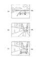
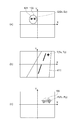
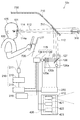
図3は、本発明の第1の実施形態に係る車載用表示システムの動作を例示する模式図である。
すなわち、同図(a)〜(c)は、異なる3つの状態における車載用表示システムの動作を例示している。
FIG. 3 is a schematic view illustrating the operation of the in-vehicle display system according to the first embodiment of the invention.
That is, FIGS. 9A to 9C illustrate the operation of the in-vehicle display system in three different states.
図3(a)に表したように、道幅が予め定められた第1の幅以上の場合は、仮想先行車両像180は予め定められた設定奥行き位置に配置される。
ここで、第1の幅は、車両730の幅よりも充分広い幅に設定され、すなわち、運転者があまり注意深く車両730を操縦しなくても、進行中の道から外れたり、ガードレールや溝、縁石等の道の境界に接触したり、対向車両などとすれ違い時に危険を感じたりしないで、走行できる幅に設定される。
As shown in FIG. 3A, when the road width is equal to or larger than a predetermined first width, the virtual
Here, the first width is set to a width that is sufficiently wider than the width of the
例えば、第1の幅は、車両730の幅に2mを加えた値に設定される。すなわち、車両730の左右において1mずつの余裕がある道幅を有した道を進行する場合であり、運転者があまり注意深く車両730を操縦しなくても、安全に、危険を感じたりすることなく進行できる。
For example, the first width is set to a value obtained by adding 2 m to the width of the
なお、第1の幅は、車両730の走行速度に基づいて変えても良い。すなわち、車両730の走行速度が速い場合の第1の幅は、走行速度が遅い場合の第1の幅よりも広く設定されることができる。走行速度が速い場合は、危険度が増し、また、運転者が感じる心理的負担も大きくなるため、このように車両730の走行速度によって第1の幅を変化させることで走行支援をより効果的に行うことができる。
Note that the first width may be changed based on the traveling speed of the
また、第1の幅は、車両730の走行速度だけでなく、車両730の乗員数や積載する荷物等によって変化する車両730の重量や、車両730の周囲の明るさや走行している道の勾配、周囲の気温や天候などに基づいて変えても良い。すなわち、車両730の重量や周囲の明るさなどによって操縦性及び危険度は変化し、また道の勾配によって自動車等の停止距離が変化し、また、周囲の気温や天候などによって道路の滑りやすさが変化するので、これらを考慮して第1の幅を変えることで、より安全で便利な走行支援を行うことができる。さらに、第1の幅は、運転者の習熟度や好みに基づいて任意に設定できたり、また、いくつかの候補から選択できるようにしても良い。また、運転者の注意度は、連続走行時間やハンドル操作頻度等によって変化することから、連続走行時間やハンドル等の操作頻度等のような運転状況に基づいて第1の幅を変えても良い。
Further, the first width is not only the traveling speed of the
そして、上記において、予め定められた設定奥行き位置は、車載用表示システムが搭載されるそれぞれの車両における停止距離に基づいて定めることができる。停止距離は、後述するように、自動車等において、停止すべき事象が認識されてから自動車等が停止するまでの距離である。そして、例えば、車両730とその進路前方を走行する車両との間の車間距離が停止距離よりも大きい場合は、比較的安全である。すなわち、設定奥行き位置は、安全に停止できる停止距離に基づいて、例えば、さらに余裕を加味してそれよりも定められた値ほど遠い位置とすることができる。
In the above description, the predetermined set depth position can be determined based on the stop distance in each vehicle on which the in-vehicle display system is mounted. As will be described later, the stop distance is a distance from the recognition of an event to be stopped in a car or the like until the car or the like stops. For example, when the inter-vehicle distance between the
これにより、仮想先行車両像180が表示されている奥行き位置までは、特に著しい注意力で運転しなくても車両730は安全に走行できる。
As a result, the
そして、もし、仮想先行車両像180が表示されている奥行き位置よりも近い側に、実際の先行車両が存在している場合は、進路前方の実際の先行車両との車間距離が過度に短くなっており、危険な状態であることを運転者は容易に認識でき、安全性を向上させた走行支援ができる。
このように、車両730の幅よりも充分に広い道を走行する場合は、例えば停止距離等に基づく予め定められた設定奥行き位置に仮想先行車両像180が配置され、これにより、車両730の進路前方の先行車両と車間距離に関して、注意を喚起でき、安全な走行に対して支援を行う。
If an actual preceding vehicle is present on the side closer to the depth position where the virtual preceding
As described above, when the vehicle travels on a road sufficiently wider than the width of the
なお、仮想先行車両像180が表示されている奥行き位置よりも近い側に、実際の先行車両が存在している場合は、上記の他に、仮想先行車両像180を点滅させたり表示の色を変えたり、その他の図形やメッセージなどを併用して表示するようにしても良く、また、音声等による注意喚起を並行して行っても良い。
In addition, when the actual preceding vehicle exists on the side closer to the depth position where the virtual
上記のように、設定奥行き位置に仮想先行車両像180が固定して配置される場合を、以下では「相対距離固定配置」と呼ぶことにする。すなわち、仮想先行車両像180の配置される設定奥行き位置と車両730との相対的な距離が固定されている配置である。なお、車両730が移動しながら、車両730との距離が相対的に固定されて仮想先行車両像180が表示されるので、車両730の移動に連動して仮想先行車両像180が配置される位置に対応した進路前方の景色は順次前方に移動している。
As described above, the case where the virtual preceding
そして、図3(b)に表したように、道幅が上記の第1の幅よりも狭く、第1の幅よりも狭い予め定められた第2の幅以上の場合は、仮想先行車両像は、設定奥行き位置よりも遠い位置に配置される。ここで、第2の幅は、車両730の幅に予め定められた余裕値を加えた値とすることができ、例えば、第2の幅は、車両730が徐行しつつ進行する場合において通行可能な幅とすることができる。すなわち、その道の道幅が注意しながら徐行して通過できる道幅である場合は、仮想先行車両像180を、設定奥行き位置よりも遠い位置に配置することにより、その道が通行可能であることを運転者に知らせることができる。
As shown in FIG. 3B, when the road width is narrower than the first width and is equal to or larger than a predetermined second width narrower than the first width, the virtual preceding vehicle image is , It is arranged at a position farther than the set depth position. Here, the second width can be a value obtained by adding a predetermined margin value to the width of the
この時、仮想先行車両像180は、設定奥行き位置よりも遠い位置において、車両730からみて遠ざかるように移動しつつ配置されることができる。すなわち、例えば最初は仮想先行車両像180が設定奥行き位置に配置されているが、徐行すれば通行可能な道幅の道にさしかかったときは、仮想先行車両像180はそのときに設定奥行き位置からあたかも加速して車両730から遠ざかるように移動して配置されることにより、その道が通行可能なことを自然に違和感なく運転者に知らせることができる。
At this time, the virtual
さらに、この場合において、仮想先行車両像180は、設定奥行き位置から遠ざかるように移動しつつ配置され、そして予め定めた距離まで移動した後に、再び設定奥行き位置に配置されることができる。すなわち、徐行すれば通行可能な道幅の道にさしかかったときは、仮想先行車両像180は、あたかも加速して車両730から遠ざかるように移動して配置され、ある程度の距離まで遠ざかった後に、再び当初の設定奥行き位置に戻されて配置される。例えば、仮想先行車両像180は、あたかも加速して遠ざかり、予め定めた例えば5m〜100mの範囲のある距離まで遠ざかった後に、当初の設定奥行き位置に戻される。これにより、その道が通行可能なことをより自然に違和感なく運転者に知らせることができる。
Furthermore, in this case, the virtual
なお、上記において、道幅と第2の幅との差に基づいて、仮想先行車両像180の遠ざかる速度を変えても良い。すなわち、例えば、道幅が第2の幅に比較的近く、速度を落として充分に徐行しつつ走行すべき場合は、仮想先行車両像180の遠ざかる速度と低くし、道幅が第2の幅よりもある程度広く、それほど速度を落とさなくても安全度が低下し難い場合は、仮想先行車両像180の遠ざかる速度を高め、そのことを運転者に知らせることができる。
In the above, the speed at which the virtual
なお、上記の予め定めた距離よりも短い距離において、車両730が進行すべき方向が変わる交差点等がある場合は、その位置まで仮想先行車両像180を遠ざけて移動して配置し、その後設定奥行き距離まで戻すようにしても良い。これにより、車両730が進行すべき方向を誤って運転者に認識させることを防止できる。
If there is an intersection or the like that changes the direction in which the
なお、この場合も、上記の他に、遠ざかって表示される仮想先行車両像180の表示状態を変えたり、その他の図形やメッセージなどを併用して表示するようにしても良く、また、音声等による案内を並行して行っても良い。
In this case as well, in addition to the above, the display state of the virtual
ここで、上記のように、仮想先行車両像180が車両730の位置からみて遠ざかるように移動しつつ配置されることを、以下では「奥方移動配置」と呼ぶことにする。なお、車両730が移動しながら、車両730から見て遠ざかるように仮想先行車両像180が表示されるので、仮想先行車両像180は車両730の移動速度よりも高速で前方に移動しているように認識される。
Here, as described above, the arrangement in which the virtual
一方、図3(c)に表したように、道幅が、上記の第2の幅よりも狭い場合は、仮想先行車両像180は、道における上記の第2の幅よりも狭い位置に基づく位置に配置される。すなわち、道幅が、車両730が徐行しても通過できない幅の場合においては、その道が通行できないことを運転者に知らせる。この時、例えば、第2の幅よりも狭い道幅となる前の所定の位置に仮想先行車両像180を配置することができ、これにより事前にそのことを運転者に知らせることができる。さらに、道幅が、車両730が徐行しても通過できない幅の場合においては、上記の他に、仮想先行車両像180を点滅させたり表示の色を変えたり、その他の図形やメッセージなどを併用して表示するようにしても良く、また、音声等による注意喚起を並行して行っても良い。
On the other hand, as shown in FIG. 3C, when the road width is narrower than the second width, the virtual
ここで、上記のように、仮想先行車両像180が、車両730の位置や設定奥行き設定位置とは関係なく前方情報である道の特定位置に配置されることを、以下では「絶対固定配置」と呼ぶことにする。なお、この場合、車両730が前方に進行しながら道の特定位置に固定されて仮想先行車両像180が配置されるので、仮想先行車両像180は車両730から見て徐々に近づいて見える。「絶対固定配置」が行われる場合の車両730の走行速度は比較的遅いことが多いので、仮想先行車両像180は比較的穏やかに近づくように見える。
Here, as described above, the fact that the virtual preceding
以上のように、本実施形態に係る車載用表示システム10によれば、道幅が車両730よりも充分広い場合は、前方の車間距離に特に注意を喚起する走行支援が可能であり、そして、道幅が徐行すれば通行可能な幅の場合は、そのことを知らせ、そして、道幅が通行できないほど狭い場合は、そのことを知らせる走行支援を行うことができる。
As described above, according to the in-
なお、上記において、前方情報取得部410によって取得された前方情報とは、車両730が進行する道に関する前方情報である。すなわち、車両730の進行すると推測される経路に基づいて、前方情報が取得される。
例えば、車両730においてナビゲータシステム等によって進行する経路(ルート)が定められ、その進行経路を車両730は進行すると推定される。そして、進行中の道において、例えば交差点や分岐点にさしかかった場合には、進行すると推定される経路の道に対して前方情報が取得され、その道においての道幅が上記のように判定され、それに基づき仮想先行車両像180が生成される。そして、進行すると推測される経路の道の形状(曲がり状態等)に対応しつつ、上記の奥行き位置に仮想先行車両像180が配置される。なお、車両730の進行すると推測される経路に関しては後述する。
In the above, the forward information acquired by the forward
For example, a route (route) that travels in the
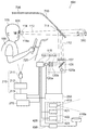
図4は、本発明の第1の実施形態に係る車載用表示システムの走行支援に係る車両の停止距離を例示する模式図である。
すなわち、同図は、一例として自動車における停止距離を例示している。
図4に表したように、車両の走行速度Vの変化と共に停止距離Dが変化する。ここで、停止距離Dは、停止すべき事象を運転者が認識してから自動車等が停止するまでの距離であり、停止すべき事象を運転者が認識してブレーキを踏みブレーキが効き始めるまでに自動車等が移動する距離である空走距離D1と、ブレーキが効き始めてから自動車等が停止するまでの距離である制動距離D2と、の合計である。
FIG. 4 is a schematic view illustrating the stop distance of the vehicle related to the travel support of the in-vehicle display system according to the first embodiment of the invention.
That is, the figure illustrates the stop distance in the automobile as an example.
As shown in FIG. 4, the stop distance D changes with the change in the traveling speed V of the vehicle. Here, the stop distance D is a distance from when the driver recognizes an event to be stopped to when the vehicle or the like stops, until the driver recognizes the event to be stopped and presses the brake to start the braking operation. Is a total of an idle running distance D1 that is a distance traveled by the automobile and a braking distance D2 that is a distance from when the brake starts to stop until the automobile stops.
例えば、車両730が50km/hで走行中の場合は、停止距離Dは32mである。この場合、設定奥行き位置は、停止位置である32mに基づいて定められる。例えば、設定奥行き位置は、32mにある余裕度を加味して、例えばある係数を乗じた値やある数値を加えた値とされ、例えば車両730よりも40m前方の位置とされる。余裕度は、例えば運転者が停止すべき事象が発生してからそれを認識するまでの時間遅れや、その他車両及び運転者、周期状況等の各種の状況を加味して定められる。
For example, when the
従って、図3(a)に関して説明したように、道幅が予め定められた第1の幅以上の場合は、仮想先行車両像180は予め定められた設定奥行き位置である、前方40mの位置に配置される。
Therefore, as described with reference to FIG. 3A, when the road width is equal to or larger than the predetermined first width, the virtual preceding
ここで、図4に例示した停止距離は一例であり、本実施形態に係る車載用表示システム10が搭載される車両によって停止距離は変化する。このため、搭載される車両の停止距離に基づいて設定奥行き幅を設定しても良い。さらに、例えば、車両730の重量や、車両730の周囲の明るさや走行している道の勾配、周囲の気温や天候などに基づいて、設定奥行き距離を変えても良い。すなわち、車両730の重量や周囲の明るさなどによって操縦性や危険度は変化し、また道の勾配によって自動車等の停止距離が変化し、また、周囲の気温や天候などによって道路の滑りやすさが変化するので、これらを考慮して設定奥行き距離を変えることでより安全で便利な走行支援を行うことができる。さらに、設定奥行き距離は、運転者の習熟度や好みに基づいて任意の設定でき、また、いくつかの候補から選択できるようにしても良い。また、運転者の注意度は、連続走行時間やハンドル等の操作頻度等によって変化することから、連続走行時間やハンドル操作等の操作頻度等のような運転状況に基づいて設定奥行き距離を変えても良い。
Here, the stop distance illustrated in FIG. 4 is an example, and the stop distance varies depending on the vehicle on which the in-
上記のように、本実施形態に係る車載用表示システム10においては、仮想先行車両像180は、前方情報内の各種の奥行き位置に配置される。すなわち、充分広い道幅の場合は、仮想先行車両像180は上記の設定奥行き位置に配置され、徐行すれば通過可能な場合は、設定奥行き位置よりも遠い位置に例えば遠ざかるように移動しつつ配置され、通過不能な道幅の場合は、通過できない道幅の位置に配置される。
As described above, in the vehicle-mounted
そして、例えば、対向車を検出した場合についても同様に表示制御を行う。例えば、通行に問題のない道では仮想先行車両像180は設定奥行き位置に配置され、車両730からみて一定の距離を保って車両730の前方に位置する。そして、すれ違い困難が予想されるがすれ違いが可能である場合には、仮想先行車両像180の表示位置を遠方移動配置として、仮想先行車両像180があたかもスピードを上げて走行するように知覚させて、対向車とすれ違いが可能であることを運転者に知らせ、その後スピードを落として元の車両間隔に戻るように知覚させる。そして、すれ違いできないと判断された場合は、その場所に仮想先行車両像180を表示して、仮想先行車両像180があたかもその場所に停止したように知覚させる。
また、進行する道に、駐車中の車両や建造物や設置物や、例えば道路工事中等のために迂回すべき表示等の障害物がある場合も、同様の動作を行うことができる。
このように、本実施形態に係る車載用表示システム10によれば、安全で便利で見やすい走行支援を行うことができる。
For example, display control is performed in the same manner when an oncoming vehicle is detected. For example, the virtual
Further, the same operation can be performed when there is a parked vehicle, a building, an installation, or an obstacle such as a display to be detoured during road construction on the traveling road.
Thus, according to the vehicle-mounted
さらに、上記では、前方の道幅(すなわち、水平方向の幅)に基づいて仮想先行車両像180の配置を変える方法に関して説明したが、前方の道の通行可能な垂直方向の幅に関しても同様の動作を実施することが可能である。すなわち、進行している道の上部に鉄道や別の道路が交差したり障害物等がある場合に、上記の第1の幅(この場合は第1の高さ)及び第2の幅(この場合は第2の高さ)に基づいて車両730が通行のし易さを判断し、仮想先行車両像180を表示することができる。
Further, in the above description, the method of changing the arrangement of the virtual
例えば、立体交差する道路や歩道橋のように充分に高い位置に別の物体が存在し、すなわち前方の道の通行可能な垂直方向の幅が第1の幅以上の場合は、仮想先行車両像180は上記の設定奥行き位置に配置される。そして、比較的低い位置に別の道路が交差して設けられているが徐行して通行可能な場合は、すなわち、高さが第1の幅よりも低いが第2の幅以上の場合は、仮想先行車両像180は、設定奥行き位置よりも遠い位置に例えば遠ざかるように移動しつつ配置される。そして、高さが第2の幅よりも低く通過不能な場合は、仮想先行車両像180は通過できない高さの位置に基づいた位置に配置される。
For example, when another object exists at a sufficiently high position such as a three-dimensionally intersecting road or a pedestrian bridge, that is, when the width in the vertical direction in which the road ahead can pass is equal to or larger than the first width, the virtual preceding
これにより、安全性を向上し、また、より便利な走行支援を提供できる。
なお、上記において、水平方向における第1の幅及び第2の幅と、垂直方向における第1の幅及び第2の幅はそれぞれ別の値とすることができる。
Thereby, safety can be improved and more convenient driving support can be provided.
In the above, the first width and the second width in the horizontal direction and the first width and the second width in the vertical direction can be set to different values.
なお、仮想先行車両像180の表示の大きさは、それぞれの位置に車両730と同じ大きさの車両がある時に運転者がその車両を認識する大きさで表示される。すなわち、仮想先行車両像180は、進路前方の景色内において仮想先行車両像180が生成される奥行き位置に車両730が存在した場合に、その車両730を観視者100が見たときに知覚する大きさで生成される。これにより、運転者は、より自然に違和感なく仮想先行車両像180を認識でき、進路前方の道幅を車両730と対比させて認識できる。さらに、奥行き位置が遠ざかるにつれて大きさが小さくなって見える効果によって、仮想先行車両像180は配置される奥行き位置をより正確に認識できる。
The display size of the virtual preceding
また、上記では、車両730が道を前進する場合について説明したが、道以外に、車庫や駐車場などにおいて障害物がある場合などにおいても同様の動作を行うことができる。例えば、障害物に挟まれた空間を車両730が通過できるかどうかによって仮想先行車両像180の配置を変えることで、そのことを知らせることができる。さらに、車両730の前方以外の方向にも表示可能にすることで、例えば、車両730が後退する場合においても、道の幅や車庫等の通行可能な幅に基づいて仮想先行車両像180を生成し、それらの幅が通行可能な幅かどうかを運転者に知らせることもできる。
In the above description, the case where the
以下では、奥行き位置の知覚に関するヒトの特性に関して説明する。
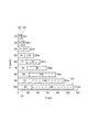
図5は、本発明の第1の実施形態に係る車載用表示システムの特性を例示するグラフ図である。
すなわち、同図は、本実施形態に係る車載用表示システム10において、設定奥行き距離Lsを変えて仮想先行車両像180を表示したときにヒトが知覚する主観的奥行き距離Lsubを調べた実験結果を例示しており、横軸は設定奥行き距離Lsであり、縦軸は主観的奥行き距離Lsubである。
In the following, human characteristics relating to the perception of depth position will be described.
FIG. 5 is a graph illustrating characteristics of the vehicle-mounted display system according to the first embodiment of the invention.
That is, this figure shows experimental results obtained by examining the subjective depth distance Lsub perceived by a human when the virtual preceding
そして、破線C1は、主観的奥行き距離Lsubと設定奥行き距離Lsとが一致する場合の特性である。
そして、実線C2は、仮想先行車両像180と観視者との距離が設定奥行き距離Lsに固定されている場合において、実際に観測された主観的奥行き距離Lsubの特性を表している。すなわち、実線C2は、「相対距離固定配置」の場合における特性である。
一方、一点鎖線C3は、仮想先行車両像180との観視者との距離が増加し、時速20km/hで遠ざかるように移動しつつある場合において、実際に観測された主観的奥行き距離Lsubの特性を表している。すなわち、一点鎖線C3は、「奥方移動配置」における特性である。
A broken line C1 is a characteristic when the subjective depth distance Lsub matches the set depth distance Ls.
A solid line C2 represents the characteristic of the subjective depth distance Lsub actually observed when the distance between the virtual preceding
On the other hand, in the case where the distance between the virtual preceding
なお、本実験においては、設定奥行き距離Lsに応じて、仮想先行車両像180の映像内における位置及び大きさが変えられている。
In this experiment, the position and size of the virtual preceding
図5に表したように、仮想先行車両像180と観視者との距離が設定奥行き距離Lsに固定されている「相対距離固定配置」の場合においては、設定奥行き距離Lsが短い場合は、実線C2と破線C1とはほぼ一致しており、主観的奥行き距離Lsubは設定奥行き距離Lsと一致する。しかし、設定奥行き距離Lsが長くなると、実線C2は破線C1よりも小さい値を推移する。
具体的には、設定奥行き距離Lsが15mと30mのときは、主観的奥行き距離Lsubは設定奥行き距離Lsと一致するが、60mと120mのときは、主観的奥行き距離Lsubは設定奥行き距離Lsよりも短くなる。そして、主観的奥行き距離Lsubと設定奥行き距離Lsとの差は、設定奥行き距離Lsが長いほど大きくなっている。
As shown in FIG. 5, in the case of “fixed relative distance arrangement” in which the distance between the virtual preceding
Specifically, when the set depth distance Ls is 15 m and 30 m, the subjective depth distance Lsub matches the set depth distance Ls. However, when the set depth distance Ls is 60 m and 120 m, the subjective depth distance Lsub is greater than the set depth distance Ls. Will also be shorter. The difference between the subjective depth distance Lsub and the set depth distance Ls increases as the set depth distance Ls increases.
実線C2(主観的奥行き距離Lsubの特性)を2次曲線で近似すると、以下の式(1)で表される。
Ls=0.0037×(Lsub)2+1.14×(Lsub) (1)
従って、式(1)に基づくと、実線C2の特性は、設定奥行き距離Lsが45mよりも小さい場合は、主観的奥行き距離Lsubは設定奥行き距離Lsと一致するが、45m以上の場合は、主観的奥行き距離Lsubは設定奥行き距離Lsよりも短くなるとすることができる。
When the solid line C2 (characteristic of the subjective depth distance Lsub) is approximated by a quadratic curve, it is expressed by the following equation (1).
Ls = 0.0037 × (Lsub) 2 + 1.14 × (Lsub) (1)
Therefore, based on Expression (1), the characteristic of the solid line C2 indicates that the subjective depth distance Lsub matches the set depth distance Ls when the set depth distance Ls is less than 45 m, but the subjective depth distance Ls exceeds 45 m. The target depth distance Lsub can be shorter than the set depth distance Ls.
そして、60m以上では、ばらつきも含めて、主観的奥行き距離Lsubは設定奥行き距離Lsよりも短くなる。 At 60 m or more, the subjective depth distance Lsub is shorter than the set depth distance Ls, including variations.
一方、仮想先行車両像180と観視者との距離が遠ざかるように移動する「奥方移動配置」の場合においては、設定奥行き距離Lsが短い場合は、一点鎖線C3と破線C1とはほぼ一致し、主観的奥行き距離Lsubは設定奥行き距離Lsと一致するが、設定奥行き距離Lsが長くなると、一点鎖線C3は破線C1よりも若干大きい値を推移する。
具体的には、設定奥行き距離Lsが15mと30mのときは、主観的奥行き距離Lsubは設定奥行き距離Lsと一致するが、60mと120mのときは、主観的奥行き距離Lsubは設定奥行き距離Lsよりも若干長くなる。そして、60mと120mのときにおいて、主観的奥行き距離Lsubと設定奥行き距離Lsとの差は、ほぼ一定であり、主観的奥行き距離Lsubは設定奥行き距離Lsよりも8m〜15m程度長い。
On the other hand, in the case of “backward movement arrangement” in which the distance between the virtual
Specifically, when the set depth distance Ls is 15 m and 30 m, the subjective depth distance Lsub matches the set depth distance Ls. However, when the set depth distance Ls is 60 m and 120 m, the subjective depth distance Lsub is greater than the set depth distance Ls. Is also slightly longer. At 60 m and 120 m, the difference between the subjective depth distance Lsub and the set depth distance Ls is substantially constant, and the subjective depth distance Lsub is about 8 m to 15 m longer than the set depth distance Ls.
ただし、実線C2で例示した「相対距離固定配置」の場合と比較すると、一点鎖線C3で例示した「奥方移動配置」の場合においては、主観的奥行き距離Lsubは設定奥行き距離Lsに相対的に良く一致していると言える。単眼視HUDでは、表示される物体(ここでは仮想先行車両像180)の知覚される奥行き位置は、背景との重ね合わせ位置に大きく依存し、「相対距離固定配置」の場合にように、位置がずれると知覚される奥行き位置誤差が大きくなる。そして、「奥方移動配置」のように、表示される像に動きがある場合には、奥行き位置を知覚しやすく、知覚される奥行き位置誤差は小さくなる。 However, compared with the case of “relative distance fixed arrangement” illustrated by the solid line C2, the subjective depth distance Lsub is relatively better than the set depth distance Ls in the case of the “backward movement arrangement” illustrated by the dashed line C3. It can be said that they are in agreement. In the monocular HUD, the perceived depth position of the displayed object (here, the virtual preceding vehicle image 180) greatly depends on the overlapping position with the background, and as in the case of “fixed relative distance arrangement”, When the shift occurs, the perceived depth position error increases. When the displayed image has a movement as in “backward movement arrangement”, the depth position is easily perceived, and the perceived depth position error is small.
同図に例示した現象は、今回の実験で初めて見出された特性であり、本発明における仮想先行車両像180の配置は、この現象に基づいて行うことができる。すなわち、主観的奥行き距離Lsubが設定奥行き距離Lsと一致しない設定奥行き距離Lsの範囲においては、その差を補正して表示することでより正確な奥行き位置に仮想先行車両像180を配置することができる。
The phenomenon illustrated in the figure is a characteristic found for the first time in this experiment, and the placement of the virtual
すなわち、本実施形態に係る車載用表示システム10において、「相対距離固定配置」を行う場合は、以下のように行うことができる。
すなわち、例えば設定奥行き位置と車両730との距離が予め設定した距離よりも短いときは、仮想先行車両像180が配置(生成)される奥行き目標位置を、進路前方の景色内において仮想先行車両像180が配置(生成)される設定奥行き位置と一致させる。
That is, in the in-
That is, for example, when the distance between the set depth position and the
そして、設定奥行き位置と車両730との距離が予め設定した距離以上のときは、仮想先行車両像180が配置(生成)される奥行き目標位置は、進路前方の景色内において仮想先行車両像180が配置(生成)される奥行き位置よりも観視者100からみて遠くに配置させる。
When the distance between the set depth position and the
すなわち、設定奥行き位置と車両730との距離が予め設定した距離以上のときは、映像内において、仮想先行車両像180に対応する進路前方の景色内の奥行き位置よりも遠い位置になるように奥行き目標位置を補正し、その補正された奥行き目標位置に仮想先行車両像180を配置(生成)する。
That is, when the distance between the set depth position and the
上記において、予め設定した距離として、45m及び60mのいずれかを用いることができる。すなわち、45mは、主観的奥行き距離Lsubが設定奥行き距離Lsよりも短くなり始める距離であり、予め設定した距離として45mを採用すると、主観的奥行き距離Lsubを設定奥行き距離Lsと精度良く一致させることができる。一方、60mは、主観的奥行き距離Lsubが設定奥行き距離Lsよりも実質的に(ばらつきを含めて)短くなり始める距離であり、予め設定した距離として60mを採用すると、主観的奥行き距離Lsubを設定奥行き距離Lsと実質的に問題なく一致させることができる。 In the above, either 45 m or 60 m can be used as the preset distance. That is, 45 m is the distance at which the subjective depth distance Lsub starts to become shorter than the set depth distance Ls. When 45 m is adopted as the preset distance, the subjective depth distance Lsub is made to coincide with the set depth distance Ls with high accuracy. Can do. On the other hand, 60 m is a distance at which the subjective depth distance Lsub starts to become substantially shorter (including variations) than the set depth distance Ls. When 60 m is used as a preset distance, the subjective depth distance Lsub is set. The depth distance Ls can be substantially matched with no problem.
このとき、式(1)の特性を基に、主観的奥行き距離Lsubが設定奥行き距離Lsと一致するように、設定奥行き距離Ls(すなわち、目標奥行き位置)を補正して、仮想先行車両像180を表示することができる。例えば、主観的奥行き距離Lsubを90mにしたいときは、式(1)に従って、設定奥行き位置Ls(すなわち、目標奥行き位置)を133mに補正して、仮想先行車両像180を表示する。
At this time, based on the characteristic of Expression (1), the set depth distance Ls (that is, the target depth position) is corrected so that the subjective depth distance Lsub matches the set depth distance Ls, and the virtual
なお、上記の予め設定した距離としては、45mや60m以外でも良く、観視者100の好みや、車載用表示システム10が搭載される車両730の仕様によっては、上記の予め設定した距離は、例えば、45mと60mとの間の例えば50mや、場合によっては60mよりも大きくても良い。
The preset distance may be other than 45 m or 60 m. Depending on the preference of the
また、予め設定した距離の前後で、上記の補正処理の程度を不連続的に行うのではなく、例えば、式(1)を満足するように、連続的に上記の補正処理を行っても良い。また、式(1)は実線C2の特性を2次関数として表現したが、その他の関数で表現しても良い。すなわち、予め設定した距離よりも長い距離の場合に、実線C2の特性を補正するように、主観的奥行き距離Lsubに適合するように、設定奥行き距離Ls、すなわち、奥行き目標位置が補正されれば良く、その補正処理の際に用いる関数は任意である。 Further, the above correction processing may be performed continuously so as to satisfy the formula (1), for example, instead of discontinuously performing the above correction processing before and after a preset distance. . Further, although the expression (1) represents the characteristic of the solid line C2 as a quadratic function, it may be expressed by other functions. That is, when the distance is longer than a preset distance, the set depth distance Ls, that is, the depth target position is corrected so as to match the subjective depth distance Lsub so that the characteristic of the solid line C2 is corrected. The function used for the correction process is arbitrary.
一方、本実施形態に係る車載用表示システム10において、「奥方移動配置」を行う場合は、以下のように行うことができる。
すなわち、例えば設定奥行き位置と車両730との距離が予め設定した距離よりも短いときは、仮想先行車両像180が配置(生成)される奥行き目標位置を、進路前方の景色内において仮想先行車両像180が配置(生成)される設定奥行き位置と一致させる。
On the other hand, in the in-
That is, for example, when the distance between the set depth position and the
そして、設定奥行き位置と車両730との距離が予め設定した距離以上のときは、仮想先行車両像180が配置(生成)される奥行き目標位置は、進路前方の景色内において仮想先行車両像180が配置(生成)される奥行き位置よりも観視者100からみて近くに配置させる。
When the distance between the set depth position and the
すなわち、設定奥行き位置と車両730との距離が予め設定した距離以上のときは、映像内において、仮想先行車両像180に対応する進路前方の景色内の奥行き位置よりも近い位置になるように奥行き目標位置を補正し、その補正された奥行き目標位置に仮想先行車両像180を配置(生成)する。
That is, when the distance between the set depth position and the
上記において、予め設定した距離として、30m及び60mのいずれかを用いることができる。すなわち、30mは、主観的奥行き距離Lsubが設定奥行き距離Lsよりも長くなり始める距離であり、予め設定した距離として30mを採用すると、主観的奥行き距離Lsubを設定奥行き距離Lsと精度良く一致させることができる。一方、60mは、主観的奥行き距離Lsubが設定奥行き距離Lsよりも実質的に(ばらつきを含めて)長くなり始める距離であり、予め設定した距離として60mを採用すると、主観的奥行き距離Lsubを設定奥行き距離Lsと実質的に問題なく一致させることができる。 In the above, either 30 m or 60 m can be used as the preset distance. That is, 30 m is a distance at which the subjective depth distance Lsub starts to be longer than the set depth distance Ls. When 30 m is used as the preset distance, the subjective depth distance Lsub is made to coincide with the set depth distance Ls with high accuracy. Can do. On the other hand, 60 m is a distance at which the subjective depth distance Lsub starts to become substantially longer (including variations) than the set depth distance Ls. When 60 m is used as a preset distance, the subjective depth distance Lsub is set. The depth distance Ls can be substantially matched with no problem.
このとき、一点鎖線C3の特性を基に、主観的奥行き距離Lsubが設定奥行き距離Lsと一致するように、設定奥行き距離Ls(すなわち、目標奥行き位置)を補正して、仮想先行車両像180を表示することができる。例えば、主観的奥行き距離Lsubを90mにしたいときは、一点鎖線C3の特性に従って、設定奥行き位置Ls(すなわち、目標奥行き位置)を75mに補正して、仮想先行車両像180を表示する。
At this time, the set depth distance Ls (that is, the target depth position) is corrected so that the subjective depth distance Lsub matches the set depth distance Ls based on the characteristics of the one-dot chain line C3, and the virtual
ただし、既に説明したように、「奥方移動配置」の場合には、主観的奥行き距離Lsubと設定奥行き距離Lsとの差は余り大きくないので、設定奥行き位置と車両730との距離に係わらず、仮想先行車両像180が配置される奥行き目標位置を、前方情報における設定奥行き位置と一致させても良い。
However, as already described, in the case of “backward movement arrangement”, the difference between the subjective depth distance Lsub and the set depth distance Ls is not so large, so regardless of the distance between the set depth position and the
このように、今回初めて明らかになったヒトの奥行き知覚に関する特性に基づいて補正して仮想先行車両像180を配置することで、より正確な奥行き位置に知覚させることが可能となる。
In this way, by arranging the virtual preceding
以下では、仮想先行車両像180の奥行き位置の配置の方法について説明する。
単眼視HUDにおいては、両眼視差による奥行き手がかりがなくなり、観視者100にとって仮想先行車両像180の奥行き位置があいまいになるので、仮想先行車両像180の奥行き位置を特定しにくい。
発明者は単眼視において用いることができる有効な奥行き手がかりについて調査した。その結果、単眼視HUDにおいては、仮想先行車両像180の位置と背景位置との相対的な「位置」が奥行き知覚に大きく影響することを見出した。すなわち、仮想先行車両像180の位置と背景位置との相対的な「位置」を制御することで、奥行き位置を精度良く認知させることができる。なお、この他、奥行き位置によって変化する「大きさ」や「運動視差」を用いて奥行き位置を制御することもできる。
Below, the method of arrangement | positioning of the depth position of the virtual preceding
In monocular HUD, there is no depth cue due to binocular parallax, and the depth position of the virtual
The inventors investigated effective depth cues that can be used in monocular vision. As a result, it was found that in monocular HUD, the relative “position” between the position of the virtual
以下では、「位置」による仮想先行車両像180の奥行き位置の配置の方法について詳しく説明する。すなわち、設定奥行き距離Lsの変化に対応する表示映像内の「位置」の制御について説明する。
Hereinafter, a method of arranging the depth position of the virtual
図6は、本発明の第1の実施形態に係る車載用表示システムにおける座標系を例示する模式図である。
すなわち、同図(a)は観視者100の頭上からみたときの模式図であり、同図(b)は観視者100の側面方向から見たときの模式図である。
FIG. 6 is a schematic view illustrating a coordinate system in the in-vehicle display system according to the first embodiment of the invention.
That is, FIG. 4A is a schematic diagram when viewed from the overhead of the
ここで、同図(a)及び(b)に表したように、一例として、三次元直交座標系を用いる。すなわち、地面に対して垂直方向をY軸とし、車両730の進行方向をZ軸とし、Y軸とZ軸とに直交する軸をX軸とする。観視者100にとって見れば、観視者100の上方向がY軸方向であり、進行方向がZ軸方向であり、左右方向がX軸方向となる。
ここで、観視者100の観視する片目(例えば、優位眼であり、例えば右目)101の位置を片目位置E(Ex、Ey、Ez)とする。
そして、本実施形態に係る車載用表示システム10によって形成される仮想先行車両像180が、車両730の反射体711において反射される位置を、仮想先行車両像位置P(Px、Py、Pz)とする。仮想先行車両像位置Pは、仮想先行車両像180の基準となる位置とすることができ、例えば、仮想先行車両像180の形状の中心や重心とすることができる。
Here, as shown in FIGS. 4A and 4B, a three-dimensional orthogonal coordinate system is used as an example. That is, the direction perpendicular to the ground is the Y axis, the traveling direction of the
Here, the position of one eye (for example, the dominant eye, for example, the right eye) 101 viewed by the
And the position where the virtual
ここで、所定の基準位置O(0、h1、0)を定める。ここで座標軸の原点を地面に接する位置とし、(0、0、0)とする。すなわち、基準位置Oは、座標軸の原点から高さh1の位置である。 Here, a predetermined reference position O (0, h1, 0) is determined. Here, the origin of the coordinate axes is the position in contact with the ground, and is (0, 0, 0). That is, the reference position O is a position having a height h1 from the origin of the coordinate axis.
そして、上記の所定の基準位置Oからみたときに、仮想先行車両像180の虚像が光学的に形成される位置を虚像位置Q(Qx、Qy、Qz)とする。
A position where the virtual image of the virtual
基準位置Oからみて、片目位置EのX軸方向におけるシフト量がw1であり、仮想先行車両像位置PのX軸方向におけるシフト量がw2であり、虚像位置QのX軸方向におけるシフト量がw3である。
一方、座標軸の原点からみて、片目位置EのY軸方向におけるシフト量がEyであり、基準位置Oからみて、仮想先行車両像位置PのY軸方向におけるシフト量が(h1−h2)であり、虚像位置QのY軸方向におけるシフト量が(h1−h3)である。
From the reference position O, the shift amount in the X-axis direction of the one-eye position E is w1, the shift amount in the X-axis direction of the virtual preceding vehicle image position P is w2, and the shift amount in the X-axis direction of the virtual image position Q is w3.
On the other hand, when viewed from the origin of the coordinate axes, the shift amount in the Y-axis direction of the one-eye position E is Ey, and when viewed from the reference position O, the shift amount in the Y-axis direction of the virtual preceding vehicle image position P is (h1-h2). The shift amount of the virtual image position Q in the Y-axis direction is (h1-h3).
また、基準位置Oと仮想先行車両像位置Pとの間のZ軸方向の距離を仮想先行車両像距離Iとし、基準位置Oと虚像位置Qとの間のZ軸方向の距離を虚像距離Lとする。虚像距離Lは、設定奥行き距離Lsに対応する。 A distance in the Z-axis direction between the reference position O and the virtual preceding vehicle image position P is a virtual preceding vehicle image distance I, and a distance in the Z-axis direction between the reference position O and the virtual image position Q is a virtual image distance L. And The virtual image distance L corresponds to the set depth distance Ls.
なお、仮想先行車両像180を配置する際には虚像位置Qは、奥行き目標位置となり、基準位置Oからみて設定奥行き距離Lsの位置が奥行き目標位置となる。
When the virtual
ここで、片目位置E(Ex、Ey、Ez)及び仮想先行車両像位置P(Px、Py、Pz)のZ軸方向の位置の変化は実質的に小さいので説明を省略して、片目位置E(Ex、Ey)及び仮想先行車両像位置P(Px、Py)と記述することにする。すなわち、仮想先行車両像位置P(Px、Py)のX−Y平面内における配置方法について説明する。 Here, since the change in the position of the one-eye position E (Ex, Ey, Ez) and the virtual preceding vehicle image position P (Px, Py, Pz) in the Z-axis direction is substantially small, the description is omitted, and the one-eye position E (Ex, Ey) and virtual preceding vehicle image position P (Px, Py) will be described. That is, a method for arranging the virtual leading vehicle image position P (Px, Py) in the XY plane will be described.
図7は、本発明の第1の実施形態に係る車載用表示システムにおける座標を例示する模式図である。
すなわち、同図(a)、(b)及び(c)は、それぞれ、X−Y平面における、上記の片目位置E(Ex、Ey)、後述する前方表示位置T(Tx、Ty)、及び、仮想先行車両像位置P(Px、Py)を例示している。
FIG. 7 is a schematic view illustrating coordinates in the in-vehicle display system according to the first embodiment of the invention.
That is, (a), (b) and (c) in the figure are the one-eye position E (Ex, Ey), the forward display position T (Tx, Ty), which will be described later, and the XY plane, respectively. The virtual leading vehicle image position P (Px, Py) is illustrated.
同図(a)は、撮像部211によって撮像された観視者100の頭部105の撮像画像を例示している。同図(a)に表したように、この撮像画像が画像処理部212で画像処理され、演算部213によって、観視者100の片目101の位置が判断され、検出される。このようにして、基準位置Oから見たときの片目101の位置である片目位置E(Ex、Ey)が、位置検出部210によって検出される。すなわち、Ex及びEyが位置検出部210によって算出される。
FIG. 4A illustrates a captured image of the
同図(b)は、前方情報取得部410で取得された前方情報を例示している。前方情報取得部410は、例えば、予め格納された例えば道路状況に関するデータを読み出すことにより、また、車両730から撮像した前方の撮像データなどによって、道路や交差点の形状などの前方情報を取得する。この具体例では、道路の幅や形状や道路のそれぞれの位置における車両730(観視者100)からの距離や、道路の起伏などが前方情報として取得される。
FIG. 6B illustrates the forward information acquired by the forward
そして、同図(b)に表したように、前方情報において仮想先行車両像180を表示すべき位置に対応する位置が求められる。すなわち、例えば、車両730の進行する道において仮想先行車両像180を表示すべき奥行き位置に対応した前方情報における位置が、前方表示位置T(Tx、Ty)として求められる。すなわち、Tx及びTyが求められる。この動作は、例えば、映像データ生成部130によって行われる。
Then, as shown in FIG. 5B, a position corresponding to the position where the virtual
同図(c)は、車載用表示システム10によって、車両730の反射体711に投影される仮想先行車両像180の位置である仮想先行車両像位置P(Px、Py)を例示している。この仮想先行車両像位置P(Px、Py)は、上記の片目位置E(Ex、Ey)及び前方表示位置T(Tx、Ty)に基づいて定められる。この動作は、例えば、映像データ生成部130によって行われる。
FIG. 6C illustrates a virtual leading vehicle image position P (Px, Py) that is the position of the virtual
すなわち、本実施形態に係る車載用表示システム10においては、前方情報に基づく前方表示位置T(Tx、Ty)と、検出された片目の位置、すなわち、片目位置E(Ex、Ey)と、に基づいて、仮想先行車両像180を仮想先行車両像位置P(Px、Py)に配置した映像が生成され、その映像を含む光束112を、観視者100の片目101に向けて投影する。これにより、仮想先行車両像180を任意の奥行き位置に表示し、運転者にとって見やすい表示を行う車載用表示システムが提供できる。
That is, in the in-
上記において、前方表示位置T(Tx、Ty)は、虚像位置Q(Qx、Qy)と一致させることができる。ただし、図5に関して説明したように、実線C2及び一点鎖線C3の特性を補正するように、前方表示位置T(Tx、Ty)と虚像位置Q(Qx、Qy)とが異なるように設定することもできる。以下では、まず、前方表示位置T(Tx、Ty)と虚像位置Q(Qx、Qy)とが一致するように設定する場合について、仮想先行車両像位置P(Px、Py)の設定方法に関して説明する。 In the above, the front display position T (Tx, Ty) can be matched with the virtual image position Q (Qx, Qy). However, as described with reference to FIG. 5, the front display position T (Tx, Ty) and the virtual image position Q (Qx, Qy) should be set differently so as to correct the characteristics of the solid line C2 and the alternate long and short dash line C3. You can also. In the following, first, a description will be given of a method for setting the virtual preceding vehicle image position P (Px, Py) in the case where the front display position T (Tx, Ty) and the virtual image position Q (Qx, Qy) are set to coincide with each other. To do.
図6(a)に例示したように、X軸方向に関していうと、前方表示位置T(Tx、Ty)、すなわち、虚像位置Q(Qx、Qy)のX軸方向におけるシフト量w3と、仮想先行車両像位置P(Px、Py)のX軸方向におけるシフト量w2と、の比は、虚像距離Lと仮想先行車両像距離Iとの比と同一である。従って、基準位置Oに観視者100の片目101が配置されているときは、仮想先行車両像位置P(Px、Py)のX軸方向の値すなわち、シフト量w2がw3×I/Lによって求まる。もし、観視者100の片目101が基準位置Oからずれている場合は、そのずれ量、すなわち、距離Ex(w1)によって補正すれば良い。
As illustrated in FIG. 6A, regarding the X-axis direction, the forward display position T (Tx, Ty), that is, the shift amount w3 in the X-axis direction of the virtual image position Q (Qx, Qy), and the virtual leading position The ratio of the vehicle image position P (Px, Py) to the shift amount w2 in the X-axis direction is the same as the ratio of the virtual image distance L to the virtual preceding vehicle image distance I. Therefore, when the one
一方、図6(b)に例示したように、Y軸方向に関していうと、前方表示位置T(Tx、Ty)、すなわち、虚像位置Q(Qx、Qy)のY軸方向におけるシフト量(h1−h3)と、仮想先行車両像位置P(Px、Py)のY軸方向におけるシフト量(h1−h2)と、の比は、虚像距離Lと仮想先行車両像距離Iとの比と同一である。従って、基準位置Oに観視者100の片目101が配置されているときは、仮想先行車両像位置P(Px、Py)のY軸方向の値すなわち、シフト量(h1−h2)が(h1−h3)×I/Lによって求まる。もし、観視者100の片目101が基準位置Oからずれている場合は、そのずれ量、すなわち、距離(h1−Ey)によって補正すれば良い。
On the other hand, as illustrated in FIG. 6B, regarding the Y-axis direction, the shift amount (h1−) of the front display position T (Tx, Ty), that is, the virtual image position Q (Qx, Qy), in the Y-axis direction. The ratio of h3) to the shift amount (h1-h2) in the Y-axis direction of the virtual leading vehicle image position P (Px, Py) is the same as the ratio of the virtual image distance L to the virtual leading vehicle image distance I. . Therefore, when the one
このとき、仮想先行車両像180の配置に基づいて、仮想先行車両像位置P(Px、Py)の他に、仮想先行車両像180の傾き(α、β、γ)及び大きさSの少なくともいずれかを変化させても良い。
At this time, based on the arrangement of the virtual
このようにして、任意の前方表示位置T(Tx、Ty)、すなわち、虚像位置Q(Qx、Qy)に仮想先行車両像180を表示することができる。
In this way, the virtual
これに基づいて、仮想先行車両像180を任意の奥行き位置に精度高く配置できる。すなわち、「相対固定配置」、「奥方移動配置」及び「絶対固定配置」の少なくともいずれかを、奥行き位置の認知精度を高めて実行することができる。
さらに、図5に例示した実線C2及び一点鎖線C3の特性を補正するように、前方表示位置T(Tx、Ty)と虚像位置Q(Qx、Qy)とを変えて設定することもでき、さらに奥行き位置の認知精度を高めることができる。
Based on this, the virtual
Furthermore, the front display position T (Tx, Ty) and the virtual image position Q (Qx, Qy) can be changed and set so as to correct the characteristics of the solid line C2 and the alternate long and short dash line C3 illustrated in FIG. The recognition accuracy of the depth position can be increased.
例えば、既に説明したように、通行可能な道幅が予め定められた第1の幅以上の場合は、「相対固定配置」を行う。この時は以下のように動作させることができる。 For example, as described above, when the road width that allows passage is equal to or greater than a predetermined first width, “relatively fixed arrangement” is performed. At this time, it can be operated as follows.
すなわち、道幅が第1の幅以上の場合において、進路前方の景色内において仮想先行車両像180が生成される奥行き位置と車両730との距離が予め設定した距離よりも短いときは、映像内において仮想先行車両像180が生成される目標位置は、進路前方の景色内において仮想先行車両像180が生成される位置に対応した前記映像内における位置と一致させる。これにより、仮想先行車両像180は設定奥行き位置に配置される。
That is, when the road width is equal to or larger than the first width, and the distance between the
そして、進路前方の景色内において仮想先行車両像180が生成される奥行き位置と車両730との距離が予め設定した距離以上のときは、映像内において仮想先行車両像180が生成される目標位置は、進路前方の景色内において仮想先行車両像180が生成される位置に対応した映像内における位置よりも、映像内の中心から見て外側に配置する。これにより、仮想先行車両像180は設定奥行き位置よりも遠くに配置される。
これにより、「相対固定配置」におけるヒトの奥行き知覚の特性を補正して、高い精度で奥行きを知覚させることができる。
なお、この時、既に説明したように、上記の予め定められた距離は、45m及び60mのいずれかを用いることができる。
When the distance between the depth position where the virtual
Accordingly, it is possible to correct the human depth perception characteristic in the “relatively fixed arrangement”, and to perceive the depth with high accuracy.
At this time, as described above, either one of 45 m and 60 m can be used as the predetermined distance.
また、通行可能な道幅が第1の幅よりも狭く第2の幅以上のときは、「奥方移動配置」を行う。この時は以下のように動作させることができる。 Further, when the passable road width is narrower than the first width and equal to or larger than the second width, “backward movement arrangement” is performed. At this time, it can be operated as follows.
すなわち、通行可能な道幅が第1の幅よりも狭く第2の幅以上の場合において、進路前方の景色内において仮想先行車両像180が生成される奥行き位置と車両730との距離が予め設定した距離よりも短いときは、映像内において仮想先行車両像180が生成される目標位置は、進路前方の景色内において仮想先行車両像180が生成される位置に対応した前記映像内における位置と一致させる。これにより、仮想先行車両像180は設定奥行き位置に配置される。
That is, the distance between the
そして、進路前方の景色内において仮想先行車両像180が生成される奥行き位置と車両730との距離が予め設定した距離以上のときは、映像内において仮想先行車両像180が生成される目標位置は、進路前方の景色内において仮想先行車両像180が生成される位置に対応した映像内における位置よりも、映像内の中心から見て内側に配置する。これにより、仮想先行車両像180は観視者100からみて設定奥行き位置よりも近くに配置される。
これにより、「奥方移動配置」におけるヒトの奥行き知覚の特性を補正して、高い精度で奥行きを知覚させることができる。
When the distance between the depth position where the virtual
As a result, it is possible to correct the human depth perception characteristic in the “backward movement arrangement” and to perceive the depth with high accuracy.
以上説明した本実施形態に係る車載用表示システム10の動作の一例についてフローチャート図を用いて説明する。
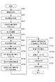
図8は、本発明の第1の実施形態に係る車載用表示システムの動作を例示するフローチャート図である。
図9は、本発明の第1の実施形態に係る車載用表示システムの構成及び動作を例示する模式図である。
An example of the operation of the in-
FIG. 8 is a flowchart illustrating the operation of the in-vehicle display system according to the first embodiment of the invention.
FIG. 9 is a schematic view illustrating the configuration and operation of the in-vehicle display system according to the first embodiment of the invention.
図8に表したように、まず、車両730の走行状態や運転状態に関する情報を取得する(ステップS270)。すなわち、図9に表したように、車両情報取得部270によって、車両730の走行速度や連続走行時間やハンドル等の操作頻度等の運転状態を検出して取得する。または、車載用表示システム10の外部に設けられた部分によって検出された車両730の運転状態に関する情報を車両情報取得部270により取得しても良い。なお、車両情報取得部270を設けず、車載用表示システム10の外部に設けられた部分によって検出された車両730の運転状態に関する情報を直接映像データ生成部130に供給しても良い。これにより、例えば、上記の設定奥行き位置や第1の幅等を設定することができる。
As shown in FIG. 8, first, information regarding the traveling state and driving state of the
そして、観視者100の片目101の位置を検出する(ステップS210)。
すなわち、図9に表したように、撮像部211によって観視者100の頭部105を撮像する(ステップS211)。そして、撮像部211によって撮像された撮像画像を、画像処理部212で画像処理し、この後の演算に用いやすいように加工する(ステップS212)。そして、画像処理部212で画像処理されたデータに基づいて、演算部213では、まず、顔の特徴点を抽出し(ステップS213a)、そして、それに基づき、眼球位置の座標を求める(ステップS213b)。これにより、片目101の位置が検出され、検出された片目101の位置データ214は、制御部250及び映像データ生成部130に供給される。
Then, the position of one
That is, as shown in FIG. 9, the
次に、図8に表したように前方情報取得部410によって、前方情報が取得される(ステップS410)。そして、例えば道幅などが、第1の幅や第2の幅と比較される。そして、表示すべき仮想先行車両像180の表示すべき奥行き位置や奥方への移動などに関するデータが算出される。
Next, as shown in FIG. 8, the front information is acquired by the front information acquisition unit 410 (step S410). Then, for example, the road width is compared with the first width and the second width. Then, data relating to the depth position to be displayed and the movement toward the back of the virtual
次に、前方表示位置T(Tx、Ty)を求める(ステップS410a)。例えば、仮想先行車両像180の表示されるべき前方情報における位置により、前方表示位置T(Tx、Ty)が求められる。また、予め設定されたに基づいて、前方表示位置T(Tx、Ty)が導出される。
Next, a front display position T (Tx, Ty) is obtained (step S410a). For example, the front display position T (Tx, Ty) is obtained from the position in the front information to be displayed of the virtual
そして、前方表示位置T(Tx、Ty)に基づいて、仮想先行車両像180を表示すべき奥行き目標位置が設定される(ステップS410b)。このとき、図5に関して説明した特性によって、設定奥行き距離Lsに基づいて補正を行うことができる。
Then, based on the front display position T (Tx, Ty), the depth target position where the virtual
そして、これに基づき、仮想先行車両像位置P(Px、Py、Pz)が導出される(ステップS410c)。なお、このとき、仮想先行車両像180の傾き(α、β、γ)及び大きさSの少なくともいずれかも変化させても良い。
Based on this, a virtual leading vehicle image position P (Px, Py, Pz) is derived (step S410c). At this time, at least one of the inclination (α, β, γ) and the size S of the virtual preceding
そして、そのデータに基づいて、仮想先行車両像180を含む映像データを生成する(ステップS131)。映像データの生成は、例えば、図9に例示した、映像データ生成部130の生成部131によって行う。
Then, based on the data, video data including the virtual preceding
そして、生成された映像データを映像歪み補正の処理を行う(ステップS132)。この処理は、例えば、図9に例示した映像歪み補正処理部132で行う。このとき、観視者100の片目101の位置データ214に基づいて、映像歪み補正の処理を行うことができる。また、フロントガラス710に設けられる反射体711や、映像投影部115の特性に基づいて映像歪み補正の処理を行うことができる。
Then, the generated video data is subjected to video distortion correction processing (step S132). This process is performed, for example, by the video distortion
そして、映像データを映像形成部110に出力する(ステップS130a)。
そして、映像形成部110では、映像データに基づき、仮想先行車両像180を有する映像を含む光束112を生成する(ステップS110)。
そして、さらに、投影部120により、生成した光束112を観視者100の片目101に向けて投影して、映像の表示を行う(ステップS120)。
Then, the video data is output to the video forming unit 110 (step S130a).
Then, the
Further, the
なお、上記において、ステップS270、S210、S410、S410a、S410b、S410c、S131、S132、S130a、S110及びS120の順序は、技術的に可能な範囲で入れ替えが可能であり、また、同時に実施することができ、また必要に応じてその一部または全部を繰り返して行うことができる。 In the above, the order of steps S270, S210, S410, S410a, S410b, S410c, S131, S132, S130a, S110, and S120 can be interchanged within a technically possible range, and should be performed simultaneously. In addition, some or all of them can be repeated as necessary.
また、図9に表したように、検出された片目101の位置データ214に基づき、制御部250の制御信号生成部251では、駆動部126aのモータを制御するモータ制御信号を生成する(ステップS251)。
そして、その信号に基づき、駆動部回路252で、駆動部126aのモータを制御するための駆動信号を生成する(ステップS252)。
そして、これにより、駆動部126aを制御し、所定の角度にミラー126を制御する。これにより、観視者100の頭部105(片目101)が動いた際にも、それに追従して、映像の呈示位置を制御することが可能となり、観視者100の頭部105の移動による映像呈示位置からの外れがなくなり、実用的な観視範囲を広くすることが可能になる。
Further, as shown in FIG. 9, the control
Based on the signal, the
And thereby, the
なお、図3(a)に関して既に説明したように、道幅が予め定められた第1の幅以上の場合は、仮想先行車両像180は予め定められた設定奥行き位置に配置(生成)されるが、本発明はこれに限定されない。すなわち、道幅が予め定められた第1の幅以上の場合において、車両730からみて前方に先行車両が実際に存在し、例えば、その実際の先行車両が車両730の位置や設定奥行き位置から所定の範囲内にある場合は、実際の先行車両の奥行き位置に仮想先行車両像180を配置(生成)しても良い。
As already described with reference to FIG. 3A, when the road width is equal to or larger than the predetermined first width, the virtual
例えば、実際に存在する先行車両が、仮想先行車両像180が表示されるべき設定奥行き位置からある程度近い位置にある場合、仮想先行車両像180をその設定奥行き位置に配置すると仮想先行車両像180と実際の先行車両の像とが重なって見え、違和感が生じる。これに対し、例えば実際の先行車両が設定奥行き位置からある程度近い場合には、仮想先行車両像180を実際の先行車両の位置に配置し、実際の先行車両の位置が設定奥行き位置からある程度遠い場合には、仮想先行車両像180を設定奥行き位置に配置することで上記のような違和感を低減することができる。
For example, when the preceding vehicle that actually exists is located at a position that is somewhat close to the set depth position where the virtual preceding
さらに、前方に先行車両が実際に存在する場合には、道幅とは関係なく、実際に存在する先行車両の奥行き位置に仮想先行車両像180を配置しても良い。これによっても、違和感を低減した表示が実現できる。
Furthermore, when a preceding vehicle is actually present ahead, the virtual
このように、車両730の進路前方の予め定められた距離以内に先行車両が存在することが検出された場合は、その先行車両の奥行き位置に仮想先行車両像180を配置(生成)することができる。また、例えば道路や建物等に設置される撮像機能やレーダ機能や、それぞれの車両に搭載される撮像機能やレーダ機能やGPS(Global Positioning System)機能を用いて、前方情報取得部410によって取得された前方情報が、車両730の進路前方の予め定められた距離以内に先行車両が存在するという情報を含んだ場合は、その先行車両の奥行き位置に仮想先行車両像180を配置することができる。
なお、このようにすることで、先行車両の有無によって仮想先行車両像180の表示または非表示を選択する必要がなくなり、より便利になる。
As described above, when it is detected that a preceding vehicle exists within a predetermined distance ahead of the course of the
By doing so, it is not necessary to select display or non-display of the virtual preceding
このとき、仮想先行車両像180は、車両730の大きさに基づいて生成されるので、実際に存在する先行車両の大きさとは異なって見えることがあるが、その時においても仮想先行車両像180が知覚される奥行き位置は、実際の先行車両の奥行き位置と同じにすることができる。この時、実際の先行車両の大きさは車両730の大きさと必ずしも一致しないので、実際の先行車両の大きさに対して仮想先行車両像180の大きさは異なって見える。
At this time, since the virtual preceding
ただし、このように、実際の先行車両の大きさと仮想先行車両像180の大きさとが異なって表示された場合に見やすさが低下する場合は、これに限らず、仮想先行車両像180の大きさを実際の先行車両の大きさと実質的に同じ大きさになるように変形しても良い。さらに、実際に存在する先行車両の大きさや形状が車両730と類似している場合は、仮想先行車両像180の形状を実際に存在する先行車両の像に似せて変形しても良い。これにより、実際の先行車両と仮想先行車両像180との像が不自然に2重に見えることがなくなりより自然な表示を提供できる。
ただし、この場合においても、進行している(進行すると推定される)道の通行可能な幅や高さの判断は、車両730の幅や高さに基づいて判定される。
However, when visibility is reduced when the actual size of the preceding vehicle and the size of the virtual preceding
However, also in this case, the determination of the width and height of a traveling road (estimated to advance) is possible based on the width and height of the
なお、既に説明したように、仮想先行車両像180の配置は、前方情報、すなわち、進行している道の曲がり等を含む形状に基づいて配置されるが、このとき、例えば、道幅のほぼ中央に配置されることができる。これにより、その道のほぼ中央を進行することを促すことができる。なお、対向車線の有無や中央分離帯の有無、さらには道幅や交通量、歩行者等の有無、車両730の進行速度等に基づいて、仮想先行車両像180のその道における配置の位置を変えても良く、これにより、さらに安全な走行支援が可能となる。
As already described, the arrangement of the virtual
なお、既に説明したように、進行する道において障害物等がある場合は、その障害物の幅を除いた道幅と見なされ、例えばその中央に仮想先行車両像180が配置される。また、進行する道において対向車がある場合は、その対向車の幅を除いた道幅がその道幅と見なされ、例えばその中央に仮想先行車両像180が配置される。
As already described, when there is an obstacle or the like on the traveling road, it is regarded as a road width excluding the width of the obstacle, and for example, the virtual
このとき、上記の障害物等や対向車は、車両730から見て見通しの悪い部分に存在するものも含む。すなわち、前方情報は、車両730から見て見通しの悪い部分に障害物等や対向車が存在するかどうかの情報も含む。例えば、道路や建物等に設置される撮像機能やレーダ機能や、それぞれの車両に搭載される撮像機能やレーダ機能やGPS機能を用いて、障害物等や対向車等に関する情報を、各道路や建物等の設置物や他車両や通信衛星等から取得して、見通しの悪い部分における障害物等や対向車等の前方情報を入手することができる。そして、見通しの悪い部分においても、上記の動作を実行し、仮想先行車両像180を生成して表示することができる。これにより、より安全な走行支援が可能となる。なお、上記の障害物等や対向車に関する情報は、前方情報取得部410によって取得することができる。
At this time, the above-described obstacles and oncoming vehicles include those present in a portion with a poor view as viewed from the
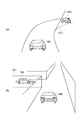
図10は、本発明の第1の実施形態に係る車載用表示システムの動作状態を例示する模式図である。
すなわち、同図(a)及び(b)は異なる状況における動作状態を例示している。
図10(a)に表したように、車両730が進行する道がカーブしており、車両から見て見通しの悪い部分521に対向車が存在する場合に、その対向車に対応した仮想他車両像190を表示することができる。これにより、カーブ等で見通しの悪い道においてもより安全な走行支援を行うことができる。
FIG. 10 is a schematic view illustrating the operation state of the in-vehicle display system according to the first embodiment of the invention.
That is, (a) and (b) in the figure illustrate the operating states in different situations.
As illustrated in FIG. 10A, when the road on which the
また、図10(b)に表したように、車両730が進行する道に交差点が存在し、その交差点の見通しが悪い部分521において、車両の進行方向に近づいてくる車両、すなわち交差点に進入する他車両がある場合に、その他車両に対応する仮想他車両像190を表示することができる。これにより、交差点に存在する建物や樹木等で見通しの悪い道においてもより安全な走行支援を行うことができる。
Further, as shown in FIG. 10B, an intersection exists on the road on which the
上記において、仮想他車両像190は、車両730からみて実際に存在する対向車や交差点に進入する他車両の奥行き位置に配置することができ、より自然に違和感なく認識することができる。これによりさらに安全性が向上する。
なお、上記において、仮想先行車両像180を同時に表示することができる。
In the above, the virtual
In the above, the virtual
このように、車載用表示システム10においては、前方情報取得部410によって得られる前方情報が、車両730から予め定められた距離以内において観視者100から見て障害物によって遮られた領域に、車両730に接近しつつ移動する他車両が存在するという情報を含んだ場合は、映像投影部115は、その検出された他車両に対応する仮想他車両像190(第2仮想画像)をさらに生成し、生成した仮想他車両像190を有する映像を含む光束112を、検出された片目101の位置に基づいて観視者100の片目に向けて投影することができる。
As described above, in the in-
以下、本実施形態に係る実施例について説明する。
(第1の実施例)
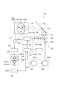
図11は、本発明の第1の実施例に係る車載用表示システムの構成を例示する模式図である。
図11に表したように、第1の実施例に係る車載用表示システム10aは、車両730の進行すると推測される経路(ルート)を生成する経路生成部450をさらに備えている。これ以外は、車載用表示システム10と同様とすることができるので説明を省略する。
Hereinafter, examples according to the present embodiment will be described.
(First embodiment)
FIG. 11 is a schematic view illustrating the configuration of an in-vehicle display system according to the first example of the invention.
As shown in FIG. 11, the in-
経路生成部450は、前方情報取得部410により取得された前方情報と、例えば、車両730の現在位置と、に基づいて、車両730の進行すると推測される経路を算出する。このとき、例えば、いくつかの経路の候補を算出し、車両730の操縦者である観視者100に選択を促して、その結果に基づき、経路を決定するようにしても良い。
The
そして、映像データ生成部130は、経路生成部450で生成された経路に基づき仮想先行車両像180を含む映像データを生成する。
Then, the video
なお、この経路生成部450は、例えば、映像データ生成部130に内蔵させることもできる。また、車載用表示システムに内蔵される各種の構成要素(後述する構成要素も含む)に内蔵されても良い。
Note that the
なお、この経路生成部450は、車載用表示システム10aに設けられなくても良い。例えば、車両730内に別途設けられるナビゲータシステムに、経路生成部450に相当する部分が設けられ、そのナビゲータシステムで生成された、車両730の進行すると推測される経路を入手して、映像データ生成部130は、仮想先行車両像180を含む映像データを生成しても良い。
さらに、経路生成部450に相当する部分は、車両730とは別に設けられても良い。この場合は、例えば無線技術によって、車両730とは別に設けられた経路生成部450に相当する部分からデータを入手して、映像データ生成部130は、仮想先行車両像180を含む映像データを生成することができる。
The
Further, a portion corresponding to the
このように、経路生成部450(及びそれに相当する部分)は、映像データ生成部130の内部または外部に設けられても良く、車載用表示システム10aの内部または外部に設けられても良く、また、車両730の内部または外部に設けられても良い。以下では、経路生成部450(及びそれに相当する部分)に関しては、省略して説明する。
As described above, the route generation unit 450 (and the corresponding part) may be provided inside or outside the video
(第2の実施例)
図12は、本発明の第2の実施例に係る車載用表示システムの構成を例示する模式図である。
図12に表したように、第2の実施例に係る車載用表示システム10bは、車両730の前方情報が予め格納された前方情報データ格納部410aを有している。これにより、前方情報取得部410は、前方情報データ格納部410aに予め格納された前方情報に関するデータを取得する。
(Second embodiment)
FIG. 12 is a schematic view illustrating the configuration of an in-vehicle display system according to the second example of the invention.
As shown in FIG. 12, the in-
前方情報データ格納部410aには、HDDなどの磁気記録再生装置やCDやDVDなどの光学的手法に基づいた記録装置や、半導体を用いた各種の記憶装置を用いることができる。
As the front information
前方情報データ格納部410aには、車両730の前方情報として、車両730の車外の、道路や交差点の形状、地名、建物や目標物などに関する各種の情報を格納することができる。これにより、前方情報取得部410は、車両730の現在位置に基づき、前方情報データ格納部410aから前方情報を読み出し、それを映像データ生成部130に供給できる。そして、上に説明したように、例えば、車両730の進行すると推測される経路に基づき、その進行すると推測される経路に対応した仮想先行車両像180に対応した前方表示位置T(Tx、Ty)が求まり、それを用いて、上記の動作を行うことができる。
In the forward information
なお、前方情報データ格納部410aに格納された情報を読み出す際には、例えば、GPSなどによって車両730(観視者100)の現在の位置を把握し、また、進行方向を把握し、これらによって、その位置と進行方向とに対応した前方情報を読み出すことができる。このような、GPSや進行方向を検出するシステムは、本実施例に係る車載用表示システム10bに内蔵しても良いし、車載用表示システム10bとは別に設け、GPSや進行方向を検出するシステムの検出結果を車載用表示システム10bに入力する形態としても良い。
また、上記の前方情報データ格納部410aは、前方情報取得部410に内蔵されても良い。
In addition, when reading the information stored in the front information
In addition, the front information
なお、第1の実施形態に係る車載用表示システム10においては、前方情報データ格納部410aが設けられておらず、この時は、例えば、前方情報データ格納部410aに相当するデータ格納部を車載用表示システム10とは別に設けることができる。この場合は、外部に設けた前方情報データ格納部410aに相当するデータ格納部のデータを車載用表示システム10に入力することにより、車載用表示システム10は上記の動作を実行することができる。
In the in-
また、前方情報データ格納部410aが車載用表示システム10に設けられない場合において、以下説明するような前方情報を検出する部分を設けることによって、前方情報データ格納部410aの機能と同様の機能を持たせることもできる。
In addition, when the front information
(第3の実施例)
図13は、本発明の第3の実施例に係る車載用表示システムの構成を例示する模式図である。
図13に表したように、第3の実施例に係る車載用表示システム10cにおいては、前方情報取得部410は、車両730の前方の前方情報を検出する前方情報検出部420を有している。本具体例では、前方情報検出部420は、前方撮像部421(カメラ)と、前方撮像部421で撮像した画像を画像解析する画像解析部422と、画像解析部422で解析された画像から、道路や交差点の形状や障害物などに関する各種の情報を抽出し、前方情報を生成する前方情報生成部423と、を有している。これにより、前方情報として、前方情報検出部420により検出された前方の道路状況(道路や交差点の形状や障害物など)に関するデータが取得される。
(Third embodiment)
FIG. 13 is a schematic view illustrating the configuration of an in-vehicle display system according to a third example of the invention.
As shown in FIG. 13, in the in-
このとき、前方撮像部421には、例えば撮像部を複数有するステレオカメラ等を用いることができ、これにより、奥行き位置に関する情報を含む前方情報を取得しやすくなる。これにより、前方映像と車両730との距離を特定することが容易となる。
At this time, for example, a stereo camera having a plurality of image capturing units can be used as the front
また、前方情報検出部420は、車両730が進行する道などに設けられたビーコンなど各種の案内信号発生器からの信号を読み取って前方情報を生成するように構成しても良い。
Further, the front
このように、本実施例に係る車載用表示システム10cにおいては、車両730の前方の前方情報を検出する前方情報検出部420を設けることで、前方情報取得部410は、時々刻々と変化する車両730の前方の前方情報を入手することができる。これにより、時々刻々と変化する前方情報を取得でき、車両730の進む方向をより精度高く算出することができ、また、仮想先行車両像180をより精度高く配置できる。
なお、上記では、仮想先行車両像180の表示に関して説明したが、仮想他車両像190に対しても同様の動作が適用可能である。
Thus, in the in-
In the above description, the display of the virtual preceding
なお、上記の前方情報データ格納部410aを用いた各種の形態の少なくとも一部と、上記の前方情報検出部420を用いた各種の形態の少なくとも一部と、を組み合わせて実施しても良い。これにより、より精度の高い前方情報が取得できる。
(第4の実施例)
図14は、本発明の第4の実施例に係る車載用表示システムの構成を例示する模式図である。
図14に表したように、第4の実施例に係る車載用表示システム10dにおいては、車両730の位置を検出する車両位置検出部430がさらに設けられている。車両位置検出部430には、例えばGPSを用いることができる。そして、仮想先行車両像180は、車両位置検出部430が検出した車両730の位置を基に生成される。
In addition, you may implement combining at least one part of the various forms using said front information
(Fourth embodiment)
FIG. 14 is a schematic view illustrating the configuration of an in-vehicle display system according to the fourth example of the invention.
As shown in FIG. 14, in the in-
すなわち、前方情報取得部410による前方情報と、車両位置検出部430が検出した車両730の位置に基づき、仮想先行車両像180が配置される。すなわち、仮想先行車両像位置P(Px、Py、Pz)が決定される。また、車両位置検出部430が検出した車両730の位置に基づき、車両730の進行すると推測される経路が求められ、その経路に基づき、仮想先行車両像180の表示の形態や、仮想先行車両像位置P(Px、Py、Pz)が決定される。なお、このとき、既に説明したように、仮想先行車両像位置(Px、Py、Pz)は、片目位置E(Ex、Ey、Pz)にも基づいて決定される。
That is, the virtual preceding
これにより、車両730の正確な位置に基づいた仮想先行車両像180を表示することができる。
Thereby, the virtual preceding
なお、本具体例では、前方情報取得部410が、前方情報検出部420(例えば、前方撮像部421、画像解析部422及び前方情報生成部423を有する)と、前方情報データ格納部410aと、を有しているが、本発明はこれに限らず、前方情報検出部420や前方情報データ格納部410aを設けなくても良い。
In this specific example, the front
すなわち、例えば、前方情報データ格納部410aに相当するデータ格納部が、車載用表示システム10が設けられる車両730の外に設けられても良く、例えば、各種の無線通信技術を応用して、前方情報データ格納部410aに相当するデータ格納部のデータを車載用表示システム10の前方情報取得部410に入力することができる。
なお、このとき、車両730に設けられるGPSや進行方向を検出するシステム(これは、本実施形態に係る車載用表示システムに内蔵しても良いし、別に設けても良い。)による車両730の位置のデータを活用して、前方情報データ格納部410aに相当するデータ格納部に格納されているデータのうちの適切なデータを車載用表示システム10に入力することができる。
なお、上記では、仮想先行車両像180の表示に関して説明したが、仮想他車両像190に対しても同様の動作が適用可能である。
That is, for example, a data storage unit corresponding to the front information
At this time, the GPS of the
In the above description, the display of the virtual preceding
(第5の実施例)
図15は、本発明の第5の実施例に係る車載用表示システムの構成を例示する模式図である。
図15に表したように、第5の実施例に係る車載用表示システム10eは、図1に例示した車載用表示システム10に対して、映像投影部115の構成が異なっている。具体的には、映像形成部110及び投影部120の構成が異なっている。また、本具体例は、制御部250が設けられていない例である。これ以外は、車載用表示システム10と同様なので説明を省略する。
(Fifth embodiment)
FIG. 15 is a schematic view illustrating the configuration of an in-vehicle display system according to the fifth example of the invention.
As shown in FIG. 15, the in-
本実施例に係る車載用表示システム10eにおいても、映像形成部110としては、例えば、LCD、DMD及びMEMS等の各種光スイッチを用いることができる。そして、映像形成部110は、映像データ生成部130から供給された仮想先行車両像180を含む映像を含む映像信号に基づいて、映像形成部110の画面に映像を形成する。
なお、映像形成部110には、レーザプロジェクタやLEDプロジェクタなどを用いることもでき、その場合は、レーザビームにより映像を形成する。
以下では、映像形成部110としてLCDを用いた場合として説明する。
Also in the in-
In addition, a laser projector, an LED projector, etc. can also be used for the
Hereinafter, the case where an LCD is used as the
そして、投影部120は、映像形成部110で形成された映像を観視者100の片目101に投影する。
Then, the projecting
投影部120には、例えば、各種の光源、投影レンズ、ミラー、及び、発散角(拡散角)を制御する各種の光学素子が用いられる。
本具体例では、投影部120には、例えば、光源121、テーパライトガイド122、第1レンズ123、可変アパーチャ124、第2レンズ125、例えば凹面状の可動式のミラー126、及び、非球面フレネルレンズ127が用いられている。
なお、例えば、第1レンズ123の焦点距離をf1、第2レンズ125の焦点距離をf2とすると、可変アパーチャ124は、第1レンズ123からf1の距離で、第2レンズ125からf2の距離の位置に設置されている。
For the
In this specific example, the
For example, if the focal length of the
そして、第2レンズ125から出射した光束は、映像形成部110に入射し、映像形成部110で形成された映像に基づいて変調された光束112となる。
Then, the light beam emitted from the
その光束112は、ミラー126及び非球面フレネルレンズ127を経て、車載用表示システム10eが搭載される車両730の例えばフロントガラス710(ウインドシールド、透明板)に設けられる反射体711により反射され、観視者100の片目101に投影される。そして観視者100は、反射体711を介して、虚像形成位置310aの位置に形成された虚像310を知覚する。このように、車載用表示システム10eは、HUDとして使用できる。
The
なお、光源121には、LEDや高圧水銀ランプ、ハロゲンランプ、レーザなど各種のものを用いることができる。また、非球面フレネルレンズ127は、例えば、フロントガラス710の形状に合わせて光束112の形(断面形状など)を制御できるように設計することができる。
As the
このような構成の車載用表示システム10eによっても、仮想先行車両像180を任意の奥行き位置に表示し、運転者にとって見やすい表示を行う車載用表示システムが提供できる。
なお、上記では、仮想先行車両像180の表示に関して説明したが、仮想他車両像190に対しても同様の動作が適用可能である。
Also with the in-
In the above description, the display of the virtual preceding
なお、この場合も、位置検出部210で検出された観視者100の片目101の位置に基づいて、映像投影部115を制御することにより、前記光束112の投影範囲114aと投影位置114の少なくともいずれかを調整する制御部250を設けても良い。例えば、制御部250は、ミラー126に連結された駆動部126aを制御して、ミラー126の角度を制御することによって、投影位置114を制御する。また、制御部250は、例えば、可変アパーチャ124を制御して投影範囲114aを制御することができる。
In this case as well, by controlling the
また、本実施例に係る車載用表示システム10eにおいて、第1〜第4の実施例に関して説明した経路生成部450、前方撮像部421、画像解析部422及び前方情報生成部423や、前方情報データ格納部410a並びに車両位置検出部430をそれぞれ単独で、または、各種の組み合わせで、設けても良い。
Further, in the in-
(第6の実施例)
本発明の第6の実施例に係る車載用表示システム10f(図示せず)は、第4の実施例に係る車載用表示システム10dにおいて、第1の実施例に係る車載用表示システム10aに関して説明した経路生成部450が設けられたものである。
(Sixth embodiment)
The in-vehicle display system 10f (not shown) according to the sixth embodiment of the present invention is the in-
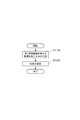
図16は、本発明の第6の実施例に係る車載用表示システムの動作を例示するフローチャート図である。
すなわち、同図は、第4の実施例に係る車載用表示システム10dにおいて、経路生成部450が設けられた場合の車載用表示システム10fの動作を例示している。ただし、既に説明したように、経路生成部450と同様の機能を有する部分を車載用表示システム10fの外に、また、車両730の外に設けても良く、この場合にも、以下に説明する動作を実施することができる。
FIG. 16 is a flowchart illustrating the operation of the in-vehicle display system according to the sixth example of the invention.
That is, this figure illustrates the operation of the in-vehicle display system 10f when the
図16に表したように、まず、車両730の進行すると推測される経路を生成する(ステップS450)。これには、例えば、前方情報データ格納部410aに格納された地図情報を用いることができる。また、車両730に搭乗する操縦者(観視者100)などによって入力される目的地に関するデータを用いることができる。また、車両位置検出部430によって検出された車両730の現在の位置に関するデータを、出発地点の位置に関するデータとして用いることもできる。なお、出発地点に関するデータは、操縦者(観視者100)などによって入力されても良い。また、既に説明したように、複数の経路の案を抽出し、それらの案から操縦者(観視者100)などに選択するように促しても良く、それにより、操縦者(観視者100)などによって入力された経路を採用することができる。
As shown in FIG. 16, first, a route that the
そして、図16に表したように、車両730の走行状態や運転状態に関する情報を取得する(ステップS270)。
And as represented to FIG. 16, the information regarding the driving | running | working state and driving | running state of the
そして、観視者100の片目101の位置を検出する(ステップS210)。
Then, the position of one
次に、前方撮像部421によって、車両730の例えば前方の前方を撮像する(ステップS421)。
そして、前方撮像部421で撮像した画像を、画像解析部422で画像解析する(ステップS422)。
そして、画像解析部422で解析された画像に基づいて、前方情報生成部423で、道路や交差点の形状や障害物などに関する各種の情報を抽出し、前方情報を生成する(ステップS423)。
そして、この前方情報生成部423で生成された前方情報が、前方情報取得部410によって取得される(ステップS410)。そして、例えば道幅などが、第1の幅や第2の幅と比較される。そして、表示すべき仮想先行車両像180の表示すべき奥行き位置や奥方への移動などに関するデータが算出される。
Next, the
Then, the
Then, based on the image analyzed by the
Then, the front information generated by the front
次に、予め設定された経路と前方情報とに基づいて、仮想先行車両像180が配置されるべき前方情報における位置として、前方表示位置T(Tx、Ty)が導出される(ステップS410a)。例えば、上記で設定された経路に対応して、仮想先行車両像180を表示する位置が、車両730の前方50m先の道路上であるとする。そのとき、前方道路上50m先の位置を前方撮像部421で認識する。そして、距離が計測され、前方表示位置T(Tx、Ty)が導出される。
Next, based on the preset route and the forward information, the forward display position T (Tx, Ty) is derived as the position in the forward information where the virtual preceding
そして、奥行き目標位置が設定される(ステップS410b)。このとき、図5に関して説明した特性によって、設定奥行き距離Lsに基づいて補正を行うことができる。
そして、これに基づき、仮想先行車両像位置P(Px、Py)が導出される(ステップS410c)。すなわち、観視者100の片目101の位置及び前方表示位置T(Tx、Ty)から、仮想先行車両像180の例えば重心位置座標、すなわち、仮想先行車両像位置P(Px、Py)を導出する。
Then, the depth target position is set (step S410b). At this time, correction can be performed based on the set depth distance Ls according to the characteristics described with reference to FIG.
Based on this, a virtual leading vehicle image position P (Px, Py) is derived (step S410c). That is, for example, the position of the center of gravity of the virtual
そして、以下、図8と同様に、仮想先行車両像位置P(Px、Py)のデータに基づいて、仮想先行車両像180を含む映像データを生成する(ステップS131)。
Thereafter, similarly to FIG. 8, video data including the virtual
そして、生成された映像データを映像歪み補正の処理を行う(ステップS132)。
そして、映像データを映像形成部110に出力する(ステップS130a)。
そして、映像形成部110では、映像データに基づき、仮想先行車両像180を有する映像を含む光束112を生成する(ステップS110)。
そして、さらに、投影部120により、生成した光束112を観視者100の片目101に向けて投影して、映像の表示を行う(ステップS120)。
Then, the generated video data is subjected to video distortion correction processing (step S132).
Then, the video data is output to the video forming unit 110 (step S130a).
Then, the
Further, the
なお、上記において、ステップS450、S270、S210、S421、S422、S423、S410、S410a、S410b、S410c、S131、S132、S130a、S110及びS120の順序は、技術的に可能な範囲で入れ替えが可能であり、また、同時に実施することができ、また必要に応じてその一部または全部を繰り返して行うことができる。 In the above, the order of steps S450, S270, S210, S421, S422, S423, S410, S410a, S410b, S410c, S131, S132, S130a, S110, and S120 can be interchanged as long as technically possible. Yes, it can be carried out at the same time, and part or all of them can be repeated as necessary.
なお、本実施形態及び上記の各種の実施例に係る車載用表示システムでは、既に説明したように、奥行き位置を2次元座標に置き換えて計算する。観視者100が前方を見ているとき、前方表示位置T(Tx、Ty)がその前方の方向に重なっている場合は、上下方向が奥行き位置に対応する。前方表示位置T(Tx、Ty)がその前方の方向からずれた位置にある場合は、上下方向の他に左右方向も奥行き位置に対応する。この画像座標を基に奥行き位置が規定される。
In the in-vehicle display system according to the present embodiment and the above-described various examples, as described above, the depth position is replaced with a two-dimensional coordinate for calculation. When the
同様に、仮想先行車両像位置P(Px、Py)がその前方の方向に重なっている場合は、上下方向が奥行き位置に対応する。仮想先行車両像位置P(Px、Py)がその前方の方向からずれた位置にある場合は、上下方向の他に左右方向も奥行き位置に対応する。このように、車載用表示システムによって表示される表示画面の上下位置(及び左右方向)が、操縦者(観視者100)にとっての奥行き位置情報となり、これにより、操縦者の位置と前方位置と表示画面との位置から仮想先行車両像180の奥行き配置位置が決定される。
Similarly, when the virtual leading vehicle image position P (Px, Py) overlaps in the forward direction, the vertical direction corresponds to the depth position. When the virtual leading vehicle image position P (Px, Py) is at a position shifted from the forward direction, the left and right direction in addition to the vertical direction also corresponds to the depth position. As described above, the vertical position (and the horizontal direction) of the display screen displayed by the in-vehicle display system is the depth position information for the operator (viewer 100). The depth arrangement position of the virtual preceding
(第2の実施の形態)
以下、本発明の第2の実施形態に係る表示方法について説明する。
図17は、本発明の第2の実施形態に係る表示方法を例示するフローチャート図である。
図17に表したように、本発明の第2の実施形態に係る表示方法では、まず、車両730の進路前方に関する情報である前方情報に基づいて、車両730の幅及び高さの少なくともいずれかに対応した大きさを有する仮想先行車両像180(第1仮想画像)を、進路前方の景色内の対応する位置に生成し、前記生成した仮想先行車両像180を有する映像を含む光束を生成する(ステップS110A)。
(Second Embodiment)
Hereinafter, a display method according to the second embodiment of the present invention will be described.
FIG. 17 is a flowchart illustrating the display method according to the second embodiment of the invention.
As shown in FIG. 17, in the display method according to the second embodiment of the present invention, first, at least one of the width and the height of the
そして、車両730に搭乗する観視者100の片目101の位置を検出し、光束112を前記検出された片目101の位置に基づいて観視者100の片目101に向けて投影する(ステップS120A)。
Then, the position of the one
これにより、仮想先行車両像180を任意の奥行き位置に配置し、運転者にとって見やすい表示を行う表示方法が提供できる。
Thereby, the display method which arrange | positions the virtual
さらに、仮想先行車両像180は、さらに、前記検出された片目101の位置に基づいて生成される。これにより、任意の奥行き位置に配置された仮想先行車両像180に関して、奥行き位置をより精度高く知覚させることができる。このように、本表示方法によれば、仮想先行車両像180等の表示を任意の奥行き位置に高い位置精度で知覚させる単眼視の表示方法が提供できる。
Further, the virtual
このとき、図3に関して説明したように、本実施形態に係る表示方法において、前方情報取得部410によって取得された前方情報は、車両730が進行すると推定される道の通行可能な水平方向及び垂直方向の少なくともいずれかの幅であり、前記幅が予め定められた第1の幅以上の場合は、仮想先行車両像180は予め定められた設定奥行き位置に配置されることができる。
At this time, as described with reference to FIG. 3, in the display method according to the present embodiment, the forward information acquired by the forward
そして、前記幅が第1の幅よりも狭く、第1の幅よりも狭い予め定められた第2の幅以上の広い場合は、仮想先行車両像180は、設定奥行き位置よりも遠い位置に配置され、前記幅が第2の幅よりも狭い場合は、仮想先行車両像180は、前記道における第2の幅よりも狭い位置に基づく位置に配置されることができる。
When the width is narrower than the first width and wider than a predetermined second width narrower than the first width, the virtual
さらに、前記幅が第1の幅よりも狭く第2の幅以上の場合は、仮想先行車両像180は、設定奥行き位置から遠ざかるように移動しつつ配置されることができる。
Further, when the width is narrower than the first width and equal to or larger than the second width, the virtual
これらの仮想先行車両像180の奥行き方向の配置においては、図5に関して説明したヒトの奥行きに関する知覚の特性に応じた補正を行うことで、より正確に奥行き位置を知覚させることができる。
In the arrangement of these virtual
以上、具体例を参照しつつ、本発明の実施の形態について説明した。しかし、本発明は、これらの具体例に限定されるものではない。例えば、車載用表示システム及び表示方法を構成する各要素の具体的な構成に関しては、当業者が公知の範囲から適宜選択することにより本発明を同様に実施し、同様の効果を得ることができる限り、本発明の範囲に包含される。
また、各具体例のいずれか2つ以上の要素を技術的に可能な範囲で組み合わせたものも、本発明の要旨を包含する限り本発明の範囲に含まれる。
The embodiments of the present invention have been described above with reference to specific examples. However, the present invention is not limited to these specific examples. For example, regarding the specific configuration of each element constituting the in-vehicle display system and the display method, those skilled in the art can appropriately implement the present invention by appropriately selecting from a well-known range and obtain the same effects. As long as it is within the scope of the present invention.
Moreover, what combined any two or more elements of each specific example in the technically possible range is also included in the scope of the present invention as long as the gist of the present invention is included.
その他、本発明の実施の形態として上述した車載用表示システム及び表示方法を基にして、当業者が適宜設計変更して実施し得る全ての車載用表示システム及び表示方法も、本発明の要旨を包含する限り、本発明の範囲に属する。 In addition, all on-vehicle display systems and display methods that can be implemented by those skilled in the art based on the above-described on-vehicle display system and display method described above as embodiments of the present invention also include the gist of the present invention. As long as it is included, it belongs to the scope of the present invention.
その他、本発明の思想の範疇において、当業者であれば、各種の変更例及び修正例に想到し得るものであり、それら変更例及び修正例についても本発明の範囲に属するものと了解される。 In addition, in the category of the idea of the present invention, those skilled in the art can conceive of various changes and modifications, and it is understood that these changes and modifications also belong to the scope of the present invention. .
10、10a〜10f 車載用表示システム
100 観視者
101 片目
105 頭部
110 映像形成部
112 光束
114 投影位置
114a 投影範囲
115 映像投影部
120 投影部
120a 結像レンズ
120b レンチキュラーレンズ
121 光源
122 テーパライトガイド
123 第1レンズ
124 可変アパーチャ
125 第2レンズ
126 ミラー
126a 駆動部
127 非球面フレネルレンズ
130 映像データ生成部
131 生成部
132 補正処理部
180 仮想先行車両像(第1仮想画像)
190 仮想他車両像(第2仮想画像)
210 位置検出部
211 撮像部
212 画像処理部
213 演算部
214 位置データ
250 制御部
251 制御信号生成部
252 駆動部回路
270 車両情報取得部
310 虚像
310a 虚像形成位置
410 前方情報取得部
410a 前方情報データ格納部
420 前方情報検出部
421 前方撮像部
422 画像解析部
423 前方情報生成部
430 車両位置検出部
450 経路生成部
510 表示映像
511 現在位置
512 建物情報等
513 表示矢印
514 車両情報
520 外界映像
521 見通しの悪い部分
710 フロントガラス
711 反射体
720 ダッシュボード
730 車両(自動車、自車両)
DESCRIPTION OF
190 Virtual other vehicle image (second virtual image)
210
Claims (15)
前記車両に搭乗する観視者の片目の位置を検出する位置検出部と、
前記前方情報取得部によって取得された前方情報に基づいて、前記車両の幅及び高さの少なくともいずれかに対応した大きさを有する第1仮想画像を、前記進路前方の景色内の対応する位置に生成し、前記生成した前記第1仮想画像を有する映像を含む光束を、前記検出された前記片目の位置に基づいて前記観視者の前記片目に向けて投影する映像投影部と、
を備えたことを特徴とする車載用表示システム。 A forward information acquisition unit that acquires forward information that is information related to the forward direction of the vehicle;
A position detector for detecting the position of one eye of a viewer boarding the vehicle;
Based on the forward information acquired by the forward information acquisition unit, a first virtual image having a size corresponding to at least one of the width and height of the vehicle is set at a corresponding position in the scenery ahead of the course. A video projection unit that generates and projects a light beam including the generated video having the first virtual image toward the one eye of the viewer based on the detected position of the one eye;
An in-vehicle display system comprising:
前記幅が予め定められた第1の幅以上の場合は、前記第1仮想画像は前記進路前方の景色内の予め定められた設定奥行き位置に生成されることを特徴とする請求項1記載の車載用表示システム。 The forward information acquired by the forward information acquisition unit includes at least one of a horizontal direction and a vertical direction in which a road on which the vehicle is estimated to travel can be passed,
The said 1st virtual image is produced | generated by the predetermined setting depth position in the scenery ahead of the course when the said width | variety is more than the predetermined 1st width | variety. In-vehicle display system.
前記進路前方の景色内において前記第1仮想画像が生成される奥行き位置と前記車両との距離が予め設定した距離以上のときは、前記第1仮想画像が生成される奥行き目標位置は、前記進路前方の景色内において前記第1仮想画像が生成される奥行き位置よりも前記観視者からみて遠くに配置されることを特徴とする請求項2記載の車載用表示システム。 The width is equal to or greater than a predetermined first width;
When the distance between the depth position where the first virtual image is generated and the vehicle in the landscape ahead of the path is equal to or greater than a preset distance, the depth target position where the first virtual image is generated is the path The in-vehicle display system according to claim 2, wherein the vehicle-mounted display system is disposed farther from the viewer than a depth position where the first virtual image is generated in a front scene.
前記進路前方の景色内において前記第1仮想画像が生成される奥行き位置と前記車両との距離が予め設定した距離以上のときは、前記映像内において前記第1仮想画像が生成される目標位置は、前記進路前方の景色内において前記第1仮想画像が生成される位置に対応した前記映像内における位置よりも、前記映像内の中心から見て外側に配置されることを特徴とする請求項2記載の車載用表示システム。 The width is equal to or greater than a predetermined first width;
When the distance between the depth position where the first virtual image is generated in the scenery ahead of the course and the vehicle is greater than or equal to a preset distance, the target position where the first virtual image is generated in the video is 3. The image display device according to claim 2, wherein the first virtual image is disposed outside the position in the image corresponding to the position where the first virtual image is generated in the scenery in front of the course as viewed from the center in the image. The on-vehicle display system described.
前記幅が前記第2の幅よりも狭い場合は、前記第1仮想画像は、前記道における前記第2の幅よりも狭い位置に基づく位置に生成されることを特徴とする請求項2〜4のいずれか1つに記載の車載用表示システム。 When the width is narrower than the first width and equal to or larger than a predetermined second width narrower than the first width, the first virtual image is the set depth position as viewed from the viewer. Is generated at a position farther than
The said 1st virtual image is produced | generated in the position based on the position narrower than the said 2nd width in the said road when the said width | variety is narrower than the said 2nd width | variety. The vehicle-mounted display system as described in any one of these.
前記進路前方の景色内において前記第1仮想画像が生成される奥行き位置と前記車両との距離が予め設定した距離以上のときは、前記第1仮想画像が生成される奥行き目標位置は、前記進路前方の景色内において前記第1仮想画像が生成される奥行き位置よりも前記観視者からみて近くに配置されることを特徴とする請求項6記載の車載用表示システム。 The width is narrower than the first width and greater than or equal to the second width;
When the distance between the depth position where the first virtual image is generated and the vehicle in the landscape ahead of the path is equal to or greater than a preset distance, the depth target position where the first virtual image is generated is the path The in-vehicle display system according to claim 6, wherein the vehicle-mounted display system is arranged closer to the viewer than a depth position where the first virtual image is generated in a front scene.
前記進路前方の景色内において前記第1仮想画像が生成される奥行き位置と前記車両との距離が予め設定した距離以上のときは、前記映像内において前記第1仮想画像が生成される目標位置は、前記進路前方の景色内において前記第1仮想画像が生成される位置に対応した前記映像内における位置よりも、前記映像内の中心から見て内側に配置されることを特徴とする請求項6記載の車載用表示システム。 The width is narrower than the first width and greater than or equal to the second width;
When the distance between the depth position where the first virtual image is generated in the scenery ahead of the course and the vehicle is greater than or equal to a preset distance, the target position where the first virtual image is generated in the video is 7. The image display device according to claim 6, wherein the first virtual image is disposed on an inner side as viewed from the center in the video than a position in the video corresponding to a position where the first virtual image is generated in a scene in front of the course. The on-vehicle display system described.
前記映像投影部は、前記映像内において、前記検出された前記他車両に対応する第2仮想画像を前記進路前方の景色内の対応する位置にさらに生成することを特徴とする請求項1〜11のいずれか1つに記載の車載用表示システム。 When the forward information includes information that there is another vehicle that moves while approaching the vehicle in a region that is blocked by the viewer within a predetermined distance from the vehicle,
The video projection unit further generates a second virtual image corresponding to the detected other vehicle in the video at a corresponding position in a scene ahead of the course. The vehicle-mounted display system as described in any one of these.
前記第1仮想画像を含む前記映像データを生成する映像データ生成部と、
前記映像データ生成部で生成された映像データに基づき前記第1仮想画像を含む映像を形成する映像形成部と、
前記映像形成部で形成された前記映像を含む光束を、前記観視者の前記片目に投影する投影部と、
前記映像投影部を制御することにより、前記光束の投影範囲及び投影位置の少なくともいずれかを調整する制御部と、
を有することを特徴とする請求項1〜13のいずれか1つに記載の車載用表示システム。 The video projection unit
A video data generation unit that generates the video data including the first virtual image;
A video forming unit for forming a video including the first virtual image based on the video data generated by the video data generating unit;
A projection unit that projects a light beam including the image formed by the image formation unit into the one eye of the viewer;
A control unit that adjusts at least one of a projection range and a projection position of the luminous flux by controlling the video projection unit;
The vehicle-mounted display system according to claim 1, wherein
前記車両に搭乗する観視者の片目の位置を検出し、前記光束を前記検出された前記片目の位置に基づいて前記観視者の前記片目に向けて投影することを特徴とする表示方法。 A first virtual image having a size corresponding to at least one of the width and height of the vehicle is generated at a corresponding position in the scenery ahead of the route based on forward information that is information related to the forward direction of the vehicle. Generating a luminous flux including a video having the generated first virtual image,
A display method comprising: detecting a position of one eye of a viewer on the vehicle, and projecting the luminous flux toward the one eye of the viewer based on the detected position of the one eye.
Priority Applications (2)
| Application Number | Priority Date | Filing Date | Title |
|---|---|---|---|
| JP2008325550A JP2010143520A (en) | 2008-12-22 | 2008-12-22 | On-board display system and display method |
| US12/568,038 US20100157430A1 (en) | 2008-12-22 | 2009-09-28 | Automotive display system and display method |
Applications Claiming Priority (1)
| Application Number | Priority Date | Filing Date | Title |
|---|---|---|---|
| JP2008325550A JP2010143520A (en) | 2008-12-22 | 2008-12-22 | On-board display system and display method |
Publications (1)
| Publication Number | Publication Date |
|---|---|
| JP2010143520A true JP2010143520A (en) | 2010-07-01 |
Family
ID=42265657
Family Applications (1)
| Application Number | Title | Priority Date | Filing Date |
|---|---|---|---|
| JP2008325550A Abandoned JP2010143520A (en) | 2008-12-22 | 2008-12-22 | On-board display system and display method |
Country Status (2)
| Country | Link |
|---|---|
| US (1) | US20100157430A1 (en) |
| JP (1) | JP2010143520A (en) |
Cited By (14)
| Publication number | Priority date | Publication date | Assignee | Title |
|---|---|---|---|---|
| JP2014006707A (en) * | 2012-06-25 | 2014-01-16 | Mitsubishi Motors Corp | Driving support device |
| CN103847640A (en) * | 2012-12-05 | 2014-06-11 | 现代自动车株式会社 | Method and apparatus for providing augmented reality |
| JP2016107945A (en) * | 2014-12-10 | 2016-06-20 | 株式会社リコー | Information providing device, information providing method, and control program for providing information |
| JP2016203850A (en) * | 2015-04-24 | 2016-12-08 | 株式会社リコー | Information providing device, information providing method and control program for providing information |
| JP2016210212A (en) * | 2015-04-30 | 2016-12-15 | 株式会社リコー | Information providing apparatus, information providing method, and information providing control program |
| JP2016218615A (en) * | 2015-05-18 | 2016-12-22 | 三菱電機株式会社 | Image synthesizing apparatus, image synthesizing method, and image synthesizing program |
| WO2018078798A1 (en) * | 2016-10-28 | 2018-05-03 | 三菱電機株式会社 | Display control device and display control method |
| JP2019089553A (en) * | 2019-02-25 | 2019-06-13 | 株式会社リコー | Image display apparatus, movable body, image display method, and program |
| WO2019176448A1 (en) * | 2018-03-15 | 2019-09-19 | マクセル株式会社 | Information display device |
| WO2019181319A1 (en) * | 2018-03-22 | 2019-09-26 | マクセル株式会社 | Information display device |
| JP2020175889A (en) * | 2020-06-29 | 2020-10-29 | 株式会社リコー | Information providing device, information providing method, and information providing control program |
| JP2020199839A (en) * | 2019-06-07 | 2020-12-17 | 株式会社デンソー | Display control device |
| JP2023060522A (en) * | 2021-10-18 | 2023-04-28 | 日産自動車株式会社 | Information presentation method and information presentation device |
| CN116249576A (en) * | 2020-09-30 | 2023-06-09 | 海思智财控股有限公司 | System and method for dynamically processing images |
Families Citing this family (55)
| Publication number | Priority date | Publication date | Assignee | Title |
|---|---|---|---|---|
| CN102149574A (en) * | 2008-09-12 | 2011-08-10 | 株式会社东芝 | Image irradiation system and image irradiation method |
| JP5161760B2 (en) * | 2008-12-26 | 2013-03-13 | 株式会社東芝 | In-vehicle display system and display method |
| JP5204309B2 (en) | 2009-09-15 | 2013-06-05 | 株式会社東芝 | Display device and control method thereof |
| WO2011036788A1 (en) | 2009-09-28 | 2011-03-31 | 株式会社 東芝 | Display device and display method |
| JP5275963B2 (en) | 2009-12-08 | 2013-08-28 | 株式会社東芝 | Display device, display method, and moving body |
| JP2011188218A (en) * | 2010-03-08 | 2011-09-22 | Toshiba Corp | Display device |
| TWI525344B (en) * | 2011-01-20 | 2016-03-11 | 緯創資通股份有限公司 | Display system, head up display, and kit for head up displaying |
| TWI446001B (en) * | 2011-10-04 | 2014-07-21 | Automotive Res & Testing Ct | Multi-optical head development device |
| US8854281B2 (en) * | 2011-12-02 | 2014-10-07 | Automotive Research & Test Center | Head up display (HUD) |
| US9230501B1 (en) | 2012-01-06 | 2016-01-05 | Google Inc. | Device control utilizing optical flow |
| US8952869B1 (en) | 2012-01-06 | 2015-02-10 | Google Inc. | Determining correlated movements associated with movements caused by driving a vehicle |
| JP5734888B2 (en) | 2012-01-31 | 2015-06-17 | 株式会社東芝 | Display device, moving body, and installation method of display device |
| US8907867B2 (en) | 2012-03-21 | 2014-12-09 | Google Inc. | Don and doff sensing using capacitive sensors |
| US10469916B1 (en) | 2012-03-23 | 2019-11-05 | Google Llc | Providing media content to a wearable device |
| JP5871739B2 (en) * | 2012-07-25 | 2016-03-01 | カルソニックカンセイ株式会社 | Vehicle display device |
| JP6121131B2 (en) * | 2012-10-16 | 2017-04-26 | アルパイン株式会社 | Multiple display device |
| TWM461063U (en) | 2013-03-07 | 2013-09-01 | Coretronic Corp | Display apparatus |
| US9514650B2 (en) | 2013-03-13 | 2016-12-06 | Honda Motor Co., Ltd. | System and method for warning a driver of pedestrians and other obstacles when turning |
| US9047703B2 (en) | 2013-03-13 | 2015-06-02 | Honda Motor Co., Ltd. | Augmented reality heads up display (HUD) for left turn safety cues |
| JP6094399B2 (en) * | 2013-06-24 | 2017-03-15 | 株式会社デンソー | Head-up display and program |
| DE102015202846B4 (en) | 2014-02-19 | 2020-06-25 | Magna Electronics, Inc. | Vehicle vision system with display |
| KR101631963B1 (en) | 2014-04-30 | 2016-06-20 | 엘지전자 주식회사 | Head up display device and vehicle having the same |
| JP2015215509A (en) | 2014-05-12 | 2015-12-03 | パナソニックIpマネジメント株式会社 | Display apparatus, display method and program |
| EP3693203B1 (en) | 2014-12-10 | 2022-05-18 | Ricoh Company, Ltd. | Controller, display, method and carrier means for information provision |
| KR101759945B1 (en) * | 2015-08-05 | 2017-07-20 | 엘지전자 주식회사 | Display Device |
| US9767687B2 (en) | 2015-09-11 | 2017-09-19 | Sony Corporation | System and method for driving assistance along a path |
| WO2017063171A1 (en) * | 2015-10-15 | 2017-04-20 | 华为技术有限公司 | Navigation system, device, and method |
| WO2017163292A1 (en) * | 2016-03-24 | 2017-09-28 | パナソニックIpマネジメント株式会社 | Headup display device and vehicle |
| EP3480647A4 (en) * | 2016-06-29 | 2020-02-19 | Nippon Seiki Co., Ltd. | DISPLAY HELMET |
| GB2557230B (en) * | 2016-11-30 | 2019-09-25 | Jaguar Land Rover Ltd | Multi-depth augmented reality display |
| JP2018105838A (en) * | 2016-12-28 | 2018-07-05 | 株式会社リコー | Information display device and vehicle device |
| JP6731644B2 (en) * | 2017-03-31 | 2020-07-29 | パナソニックIpマネジメント株式会社 | Display position correction device, display device including display position correction device, and moving body including display device |
| WO2018222122A1 (en) * | 2017-05-31 | 2018-12-06 | Uniti Sweden Ab | Methods for perspective correction, computer program products and systems |
| WO2019017198A1 (en) * | 2017-07-19 | 2019-01-24 | 株式会社デンソー | Display device for vehicle and display control device |
| DE112018003715B4 (en) * | 2017-07-19 | 2023-11-16 | Denso Corporation | VEHICLE DISPLAY DEVICE |
| DE102017214225B3 (en) * | 2017-08-15 | 2018-11-22 | Volkswagen Aktiengesellschaft | Method for operating a driver assistance system of a motor vehicle and motor vehicle |
| US10748426B2 (en) * | 2017-10-18 | 2020-08-18 | Toyota Research Institute, Inc. | Systems and methods for detection and presentation of occluded objects |
| KR102547823B1 (en) | 2017-12-13 | 2023-06-26 | 삼성전자주식회사 | Method and device to visualize content |
| US10859389B2 (en) * | 2018-01-03 | 2020-12-08 | Wipro Limited | Method for generation of a safe navigation path for a vehicle and system thereof |
| KR102518661B1 (en) * | 2018-10-16 | 2023-04-06 | 현대자동차주식회사 | Method for correction image distortion of hud system |
| US11505181B2 (en) * | 2019-01-04 | 2022-11-22 | Toyota Motor Engineering & Manufacturing North America, Inc. | System, method, and computer-readable storage medium for vehicle collision avoidance on the highway |
| JP7476568B2 (en) * | 2019-09-02 | 2024-05-01 | 株式会社アイシン | Superimposed image display device, superimposed image drawing method, and computer program |
| JP7250666B2 (en) * | 2019-11-27 | 2023-04-03 | 京セラ株式会社 | Head-up display, head-up display system and moving object |
| WO2021166814A1 (en) * | 2020-02-17 | 2021-08-26 | 株式会社小糸製作所 | Lamp system |
| CN113682315B (en) * | 2020-05-15 | 2023-06-23 | 华为技术有限公司 | Cockpit system adjustment device and method for adjusting a cockpit system |
| DE102020206246A1 (en) * | 2020-05-18 | 2021-11-18 | Ktm Ag | Reducing the risk of a collision with an undercover motor vehicle |
| CN113119975B (en) * | 2021-04-29 | 2023-03-24 | 东风汽车集团股份有限公司 | Distance identification display method, device and equipment and readable storage medium |
| CN113434620A (en) * | 2021-06-25 | 2021-09-24 | 阿波罗智联(北京)科技有限公司 | Display method, device, equipment, storage medium and computer program product |
| CN115917254B (en) * | 2021-07-31 | 2026-02-10 | 深圳引望智能技术有限公司 | A display method, apparatus and system |
| US12498239B2 (en) * | 2022-06-16 | 2025-12-16 | At&T Intellectual Property I, L.P. | System for extended reality augmentation of situational navigation |
| US12468154B2 (en) | 2022-07-01 | 2025-11-11 | Brelyon Inc. | Wearable device with 1D-1D optical surfaces for stereoscopic and monocular depth programming |
| US12466256B2 (en) * | 2022-07-01 | 2025-11-11 | Brelyon Inc. | In-vehicle display with stereoscopic and monocular depth programming |
| JP2025059826A (en) * | 2023-09-29 | 2025-04-10 | パナソニックオートモーティブシステムズ株式会社 | Display device, display method, and program |
| US12504936B2 (en) * | 2023-12-29 | 2025-12-23 | Harman International Industries, Incorporated | Windshield having zonal displays |
| CN121200769A (en) * | 2024-06-25 | 2025-12-26 | 京东方科技集团股份有限公司 | Control methods, devices, systems, and computer-readable storage media for vehicle head-up displays |
Family Cites Families (2)
| Publication number | Priority date | Publication date | Assignee | Title |
|---|---|---|---|---|
| US8686922B2 (en) * | 1999-12-15 | 2014-04-01 | American Vehicular Sciences Llc | Eye-location dependent vehicular heads-up display system |
| JP2009128565A (en) * | 2007-11-22 | 2009-06-11 | Toshiba Corp | Display device, display method, and head-up display |
-
2008
- 2008-12-22 JP JP2008325550A patent/JP2010143520A/en not_active Abandoned
-
2009
- 2009-09-28 US US12/568,038 patent/US20100157430A1/en not_active Abandoned
Cited By (27)
| Publication number | Priority date | Publication date | Assignee | Title |
|---|---|---|---|---|
| JP2014006707A (en) * | 2012-06-25 | 2014-01-16 | Mitsubishi Motors Corp | Driving support device |
| CN103847640A (en) * | 2012-12-05 | 2014-06-11 | 现代自动车株式会社 | Method and apparatus for providing augmented reality |
| JP2016107945A (en) * | 2014-12-10 | 2016-06-20 | 株式会社リコー | Information providing device, information providing method, and control program for providing information |
| US10152120B2 (en) | 2014-12-10 | 2018-12-11 | Ricoh Company, Ltd. | Information provision device and information provision method |
| US10852818B2 (en) | 2014-12-10 | 2020-12-01 | Ricoh Company, Ltd. | Information provision device and information provision method |
| JP2016203850A (en) * | 2015-04-24 | 2016-12-08 | 株式会社リコー | Information providing device, information providing method and control program for providing information |
| JP2016210212A (en) * | 2015-04-30 | 2016-12-15 | 株式会社リコー | Information providing apparatus, information providing method, and information providing control program |
| JP2016218615A (en) * | 2015-05-18 | 2016-12-22 | 三菱電機株式会社 | Image synthesizing apparatus, image synthesizing method, and image synthesizing program |
| WO2018078798A1 (en) * | 2016-10-28 | 2018-05-03 | 三菱電機株式会社 | Display control device and display control method |
| JPWO2018078798A1 (en) * | 2016-10-28 | 2019-01-24 | 三菱電機株式会社 | Display control apparatus and display control method |
| WO2019176448A1 (en) * | 2018-03-15 | 2019-09-19 | マクセル株式会社 | Information display device |
| JP2019166891A (en) * | 2018-03-22 | 2019-10-03 | マクセル株式会社 | Information display device |
| US11763781B2 (en) | 2018-03-22 | 2023-09-19 | Maxell, Ltd. | Information display apparatus |
| US12406639B2 (en) | 2018-03-22 | 2025-09-02 | Maxell, Ltd. | Information display apparatus |
| WO2019181319A1 (en) * | 2018-03-22 | 2019-09-26 | マクセル株式会社 | Information display device |
| JP2021178635A (en) * | 2018-03-22 | 2021-11-18 | マクセル株式会社 | Information display device |
| US12112724B2 (en) | 2018-03-22 | 2024-10-08 | Maxell, Ltd. | Information display apparatus |
| US11398208B2 (en) | 2018-03-22 | 2022-07-26 | Maxell, Ltd. | Information display apparatus |
| JP7233490B2 (en) | 2018-03-22 | 2023-03-06 | マクセル株式会社 | Information display device |
| JP2019089553A (en) * | 2019-02-25 | 2019-06-13 | 株式会社リコー | Image display apparatus, movable body, image display method, and program |
| JP2020199839A (en) * | 2019-06-07 | 2020-12-17 | 株式会社デンソー | Display control device |
| JP7385834B2 (en) | 2020-06-29 | 2023-11-24 | 株式会社リコー | Image display method and image display device |
| JP2022044623A (en) * | 2020-06-29 | 2022-03-17 | 株式会社リコー | Image display method and image display device |
| JP2020175889A (en) * | 2020-06-29 | 2020-10-29 | 株式会社リコー | Information providing device, information providing method, and information providing control program |
| CN116249576A (en) * | 2020-09-30 | 2023-06-09 | 海思智财控股有限公司 | System and method for dynamically processing images |
| JP2023060522A (en) * | 2021-10-18 | 2023-04-28 | 日産自動車株式会社 | Information presentation method and information presentation device |
| JP7683451B2 (en) | 2021-10-18 | 2025-05-27 | 日産自動車株式会社 | Information presentation method and information presentation device |
Also Published As
| Publication number | Publication date |
|---|---|
| US20100157430A1 (en) | 2010-06-24 |
Similar Documents
| Publication | Publication Date | Title |
|---|---|---|
| JP2010143520A (en) | On-board display system and display method | |
| JP4886751B2 (en) | In-vehicle display system and display method | |
| JP5155915B2 (en) | In-vehicle display system, display method, and vehicle | |
| US10551619B2 (en) | Information processing system and information display apparatus | |
| JP6241093B2 (en) | Head-up display device | |
| JP6201690B2 (en) | Vehicle information projection system | |
| JP6176478B2 (en) | Vehicle information projection system | |
| JP6149543B2 (en) | Head-up display device | |
| WO2011108091A1 (en) | In-vehicle display device and display method | |
| US11525694B2 (en) | Superimposed-image display device and computer program | |
| JP2019012483A (en) | Display system, information presentation system including display system, display system control method, program, and moving body including display system | |
| JP6883759B2 (en) | Display systems, display system control methods, programs, and mobiles | |
| JP6204793B2 (en) | Head-up display device | |
| JP6027498B2 (en) | Head-up display device | |
| CN104515531A (en) | Strengthened 3-dimension (3-D) navigation | |
| JP2012035745A (en) | Display device, image data generating device, and image data generating program | |
| JP2015215476A (en) | Display device | |
| JP2019116229A (en) | Display system | |
| JP2016109645A (en) | Information providing device, information providing method, and control program for providing information | |
| JP2019012238A (en) | Display system, information presentation system, method for controlling display system, program, and mobile body | |
| WO2019130860A1 (en) | Head-up display device and control program | |
| JP2015074391A (en) | Head-up display device | |
| JP2022083609A (en) | Display control device, head-up display device, and image display control method | |
| JP2015064434A (en) | Head-up display device | |
| JP2021160409A (en) | Display control device, image display device, and method |
Legal Events
| Date | Code | Title | Description |
|---|---|---|---|
| A621 | Written request for application examination |
Free format text: JAPANESE INTERMEDIATE CODE: A621 Effective date: 20110329 |
|
| A521 | Request for written amendment filed |
Free format text: JAPANESE INTERMEDIATE CODE: A523 Effective date: 20110615 |
|
| A762 | Written abandonment of application |
Free format text: JAPANESE INTERMEDIATE CODE: A762 Effective date: 20120206 |