JP2010143463A - Light control glass device - Google Patents
Light control glass device Download PDFInfo
- Publication number
- JP2010143463A JP2010143463A JP2008323831A JP2008323831A JP2010143463A JP 2010143463 A JP2010143463 A JP 2010143463A JP 2008323831 A JP2008323831 A JP 2008323831A JP 2008323831 A JP2008323831 A JP 2008323831A JP 2010143463 A JP2010143463 A JP 2010143463A
- Authority
- JP
- Japan
- Prior art keywords
- passenger
- light control
- light
- seat
- occupant
- Prior art date
- Legal status (The legal status is an assumption and is not a legal conclusion. Google has not performed a legal analysis and makes no representation as to the accuracy of the status listed.)
- Pending
Links
Images


Landscapes
- Lighting Device Outwards From Vehicle And Optical Signal (AREA)
Abstract
Description
本発明は、調光ガラス装置に関する。 The present invention relates to a light control glass device.
特許文献1には、透視用の窓ガラスの例が開示されている。この特許文献1に記載の例では、フロントガラスの一部に、光の透過率を調節可能な変色エリアが設けられており、この変色エリアには、運転席の乗員が信号機を覗けるように、小窓が設けられている。
しかしながら、特許文献1に記載の例においては、運転席の乗員の視界の確保と車室内への光の入射の抑制とをより一層効果的に両立させるためには改善の余地がある。 However, in the example described in Patent Document 1, there is room for improvement in order to more effectively achieve both the securing of the field of view of the passenger in the driver's seat and the suppression of the incidence of light into the passenger compartment.
本発明は、上記課題に鑑みてなされたものであって、運転席の乗員の視界の確保と車室内への光の入射の抑制とをより一層効果的に両立させることができる調光ガラス装置を提供することを目的とする。 The present invention has been made in view of the above-described problems, and is a light control glass device that can more effectively achieve both ensuring the visibility of a driver's occupant and suppressing the incidence of light into the passenger compartment. The purpose is to provide.
前記課題を解決するために、請求項1に記載の車両用ドア構造は、光を透過する透過状態と、前記透過状態よりも光の透過率が低い透過率低減状態とにそれぞれ変化可能な複数の調光領域を有するフロントガラスと、前記複数の調光領域のうち、運転席の乗員の眼球及び助手席の乗員の眼球と車両前方の光源とをそれぞれ結ぶ線上に位置する特定の調光領域が前記透過率低減状態にあるときに、前記運転席の乗員の視線が前記特定の調光領域を通じて車両前方に向けられた場合には、前記特定の調光領域を前記透過状態に変化させ、前記助手席の乗員の視線が前記特定の調光領域を通じて車両前方に向けられた場合には、前記特定の調光領域を前記透過率低減状態に維持する制御ユニットと、を備えている。 In order to solve the above-described problem, the vehicle door structure according to claim 1 is capable of changing between a transmission state in which light is transmitted and a transmittance reduction state in which light transmittance is lower than that in the transmission state. And a specific dimming area located on a line connecting the eyeball of the passenger in the driver's seat and the eyeball of the passenger in the front passenger seat and the light source in front of the vehicle among the plurality of dimming areas. When the line of sight of the occupant in the driver's seat is directed forward of the vehicle through the specific dimming area when the is in the reduced transmittance state, the specific dimming area is changed to the transmissive state, A control unit that maintains the specific dimming area in the reduced transmittance state when the line of sight of the passenger in the passenger seat is directed forward of the vehicle through the specific dimming area.
請求項1に記載の車両用ドア構造では、複数の調光領域のうち、運転席の乗員の眼球及び助手席の乗員の眼球と車両前方の光源とをそれぞれ結ぶ線上に位置する特定の調光領域が透過率低減状態にあるときに、運転席の乗員の視線がこの特定の調光領域を通じて車両前方に向けられた場合には、この特定の調光領域が透過状態に変化される。これにより、運転席の乗員の視界を確保することができる。 In the vehicle door structure according to claim 1, the specific light control located on the line connecting the eyeball of the passenger in the driver seat and the eyeball of the passenger in the passenger seat and the light source in front of the vehicle among the plurality of light control regions. When the line of sight of the driver's occupant is directed to the front of the vehicle through this specific dimming area when the area is in the reduced transmittance state, this specific dimming area is changed to the transmissive state. Thereby, the field of view of the driver's seat occupant can be secured.
一方、上述の特定の調光領域が透過率低減状態にあるときに、助手席の乗員の視線がこの特定の調光領域を通じて車両前方に向けられた場合でも、この特定の調光領域は透過率低減状態に維持される。これにより、車室内への光の入射を抑制することができる。 On the other hand, when the above-mentioned specific dimming area is in the reduced transmittance state, the specific dimming area is transmitted even when the line of sight of the passenger in the passenger seat is directed to the front of the vehicle through the specific dimming area. Maintained in a reduced rate state. Thereby, the incidence of light into the passenger compartment can be suppressed.
以上詳述したように、本発明によれば、運転席の乗員の視界の確保と車室内への光の入射の抑制とをより一層効果的に両立させることができる。 As described in detail above, according to the present invention, it is possible to more effectively achieve both the securing of the field of view of the driver's occupant and the suppression of the incidence of light into the passenger compartment.
[第一実施形態]
はじめに、本発明の第一実施形態について説明する。
[First embodiment]
First, a first embodiment of the present invention will be described.
図1には、本発明の第一実施形態に係る調光ガラス装置10の全体構成が示されている。
The whole structure of the light
この図に示されるように、調光ガラス装置10は、フロントガラス12と、乗員検出センサ14と、光検出センサ16と、視線検出センサ18,20と、制御ユニット22とを有して構成されている。
As shown in this figure, the light
フロントガラス12は、複数の調光領域24A〜24Fに区分されている。各調光領域24A〜24Fは、例えば、調光フィルム等を有して構成されており、印加される電圧に応じて光を透過する消色状態(透過状態)と、この消色状態よりも光の透過率が低い着色状態(透過率低減状態)とにそれぞれ変化される構成とされている。
The
乗員検出センサ14は、例えば着座センサやシートベルトセンサ等により構成されており、助手席の乗員の存在の有無に応じた信号を制御ユニット22に出力する構成とされている。
The
光検出センサ16は、例えばフロントガラス12に一体に設けられ、車両前方の光源(例えば、対向車のヘッドランプ、太陽、月、路側灯等)から出射されてフロントガラス12に入射される光の入射角度や光源の位置等に応じた信号を制御ユニット22に出力する構成とされている。
The
視線検出センサ18,20は、それぞれ例えばカメラ等により構成されている。そして、視線検出センサ18は、運転席の乗員の視線の向きに応じた信号を制御ユニット22に出力する構成とされ、視線検出センサ20は、助手席の乗員の視線の向きに応じた信号を制御ユニット22に出力する構成とされている。
The line-of-
制御ユニット22は、上述の乗員検出センサ14、光検出センサ16、視線検出センサ18,20から出力された信号に基づいて、次の如く各調光領域24A〜24Fに印加される電圧を制御する構成とされている。
The
次に、本発明の第一実施形態に係る調光ガラス装置10の動作と併せてその作用及び効果について説明する。
Next, the operation and effect will be described together with the operation of the light
図2には、制御ユニット22が複数の調光領域24A〜24Fを着色する場合の動作を表すフローチャートが示されている。
FIG. 2 shows a flowchart representing the operation when the
この図に示されるように、制御ユニット22は、先ず、ステップS1において、視線検出センサ18,20から出力された信号に基づいて、運転席の乗員及び助手席の乗員の視線の向きを検出する。
As shown in this figure, first, in step S1, the
続いて、制御ユニット22は、ステップS2において、光検出センサ16から出力された信号に基づいて、車両前方の光源(例えば、対向車のヘッドランプ、太陽、月、路側灯等)から出射されてフロントガラス12に入射される光の入射角度や光源の位置等を検出する。
Subsequently, in step S2, the
そして、制御ユニット22は、ステップS3において、上述のステップS1において検出した運転席の乗員及び助手席の乗員の視線の向きと、上述のステップS2において検出したフロントガラス12に入射される光の入射角度や光源の位置等から、複数の調光領域24A〜24Fのうち着色状態にすべき調光領域を決定し、この決定した調光領域を着色状態とする。
Then, in step S3, the
例えば、図4の上図に示されるように、車両前方の光源54としての太陽(夕日、朝日)が低い位置にある場合であって、運転席の乗員及び助手席の乗員の視線が上方の調光領域24A,24B及び中央の調光領域24C,24Dの方向に向けられていない場合には、上方の調光領域24A,24B及び中央の調光領域24C,24Dが着色状態とされる。
For example, as shown in the upper diagram of FIG. 4, when the sun (sunset, morning sun) as the
また、例えば、図5の上図に示されるように、車両前方の光源54としての太陽が高い位置にある場合であって、運転席の乗員及び助手席の乗員の視線が上方の調光領域24A,24Bの方向に向けられていない場合には、上方の調光領域24A,24Bが着色状態とされる。
In addition, for example, as shown in the upper diagram of FIG. 5, the light control area in which the sun as the
また、例えば、図6の上図に示されるように、車両前方に光源54としてヘッドランプを点灯している対向車がある場合であって、運転席の乗員及び助手席の乗員の視線が下方の調光領域24E,24Fの方向に向けられていない場合には、このヘッドランプのロービーム及びハイビームの切替状況等に応じて、下方の調光領域24E,24Fが着色状態とされる。
Further, for example, as shown in the upper diagram of FIG. 6, there is an oncoming vehicle in which a headlamp is lit as a
続いて、制御ユニット22は、上述の図2のフローチャートで示される動作を完了すると、図3のフローチャートで示される動作に移行する。
Subsequently, when the operation shown in the flowchart of FIG. 2 is completed, the
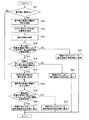
図3には、制御ユニット22が複数の調光領域24A〜24Fを消色する場合の動作を表すフローチャートが示されている。
FIG. 3 shows a flowchart showing the operation when the
この図に示されるように、制御ユニット22は、先ず、ステップS11において、乗員検出センサ14から出力された信号に基づいて、助手席の乗員の存在の有無を判断する。
As shown in the figure, the
ここで、制御ユニット22は、ステップS11において、助手席に乗員が存在しないと判断した場合には、後述するステップS18に移行する。
If the
一方、制御ユニット22は、ステップS11において、助手席に乗員が存在すると判断した場合には、ステップS12において、視線検出センサ20から出力された信号に基づいて、助手席の乗員の視線の向きを検出する。
On the other hand, if the
続いて、制御ユニット22は、ステップS13において、光検出センサ16から出力された信号に基づいて、車両前方の光源(例えば、対向車のヘッドランプ、太陽、月、路側灯等)から出射されてフロントガラス12に入射される光の入射角度や光源の位置等を検出する。
Subsequently, in step S13, the
そして、制御ユニット22は、ステップS14において、上述のステップS13において検出したフロントガラス12に入射される光の入射角度や光源の位置等から、複数の調光領域24A〜24Fのうち、車両前方の光源から予め定められた基準値よりも強い光が入射されている調光領域(つまり、運転席の乗員の眼球50と車両前方の光源54とを結ぶ線L1上に位置すると共に助手席の乗員の眼球52と車両前方の光源54とを結ぶ線L2上に位置する調光領域)を特定する。
Then, in step S14, the
すなわち、この特定されるべき調光領域は、図4の場合、太陽が位置する側に配置された左上及び左中央の調光領域24A,24Cであり、図5の場合、太陽が位置する側に配置された左上の調光領域24Aであり、図6,図7の場合、対向車が位置する側に配置された右下の調光領域24Fである。
That is, the dimming area to be specified is the upper left and left
続いて、制御ユニット22は、ステップS15において、上述のステップS12において検出した助手席の乗員の視線の向きに基づいて、助手席の乗員の視線が向けられている方向にある調光領域が着色状態にあるか否かを判断する。
Subsequently, in step S15, the
そして、制御ユニット22は、ステップS15において、助手席の乗員の視線が向けられている方向にある調光領域が着色状態にあると判断した場合には、ステップS16において、助手席の乗員の視線が向けられている方向にある調光領域が、上述のステップS13において特定した調光領域(特定の調光領域)であるか否かを判断する。
When the
ここで、制御ユニット22は、ステップS16において、助手席の乗員の視線が向けられている方向にある調光領域が、上述のステップS13において特定した調光領域でないと判断した場合には、ステップS22において、この調光領域を消色状態に変化させる。
Here, if the
例えば、図4,図5の下図のように、助手席の乗員の視線が右上の調光領域24Bを通じて車両前方に向けられた場合には、この右上の調光領域24Bが消色状態に変化される。
For example, as shown in the lower diagrams of FIGS. 4 and 5, when the line of sight of the passenger in the passenger seat is directed to the front of the vehicle through the upper
なお、制御ユニット22は、上述のステップS15において、助手席の乗員の視線が向けられている方向にある調光領域が着色状態にないと判断した場合には、ステップS21において、助手席の乗員の視線が向けられている方向にある調光領域を消色状態に維持する。
If the
そして、制御ユニット22は、ステップS21又はステップS22の後に、後述するステップS18に移行する。
And the
一方、制御ユニット22は、ステップS16において、助手席の乗員の視線が向けられている方向にある調光領域が、上述のステップS13において特定した調光領域(特定の調光領域)であると判断した場合には、ステップS17において、この特定の調光領域を着色状態に維持する。
On the other hand, in step S16, the
つまり、例えば、図6の下図のように、予め定められた基準値よりも強い光が入射されていると特定された右下の調光領域24Fが着色状態にあるときに、助手席の乗員の視線が右下の調光領域24Fを通じて車両前方に向けられた場合には、この右下の調光領域24Fが着色状態に維持される。
That is, for example, as shown in the lower diagram of FIG. 6, when the lower right dimming area 24 </ b> F that is identified as being incident with light that is stronger than a predetermined reference value is in a colored state, the passenger in the passenger seat Is directed to the front of the vehicle through the lower
これにより、車室内への光の入射が抑制されるので、運転席の乗員が防眩される。また、車両前方の光源が太陽である場合には、運転席の乗員が防眩されることに加え、車室内の温度上昇が抑制される。 Thereby, since the incidence of light into the passenger compartment is suppressed, the driver's seat occupant is anti-glare. Further, when the light source in front of the vehicle is the sun, the passenger in the driver's seat is prevented from glare and temperature rise in the passenger compartment is suppressed.
続いて、制御ユニット22は、ステップS18において、視線検出センサ18から出力された信号に基づいて、運転席の乗員の視線の向きを検出する。
Subsequently, in step S18, the
そして、制御ユニット22は、ステップS19において、上述のステップS18において検出した運転席の乗員の視線の向きに基づいて、運転席の乗員の視線が向けられている方向にある調光領域が着色状態にあるか否かを判断する。
In step S19, the
ここで、制御ユニット22は、ステップS19において、運転席の乗員の視線が向けられている方向にある調光領域(上述のステップS13において特定した調光領域を含む)が着色状態にないと判断した場合には、ステップS23において、この調光領域を消色状態に維持し、一連の処理を終了する。
Here, in step S19, the
一方、制御ユニット22は、ステップS19において、運転席の乗員の視線が向けられている方向にある調光領域(上述のステップS13において特定した調光領域を含む)が着色状態にあると判断した場合には、ステップS20において、この調光領域を消色状態に変化させる。
On the other hand, in step S19, the
例えば、図4の下図のように、運転席の乗員の視線が右中央の調光領域24Dを通じて車両前方に向けられた場合には、この右中央の調光領域24Dが消色状態に変化される。
For example, as shown in the lower diagram of FIG. 4, when the line of sight of the driver in the driver's seat is directed forward of the vehicle through the right
また、例えば、図7の下図のように、運転席の乗員の視線が向けられた方向にある調光領域が上述のステップS13において特定した調光領域24Fである場合であっても、運転席の乗員の視線がこの調光領域24Fを通じて車両前方に向けられた場合には、この調光領域24Fが消色状態に変化される。これにより、運転席の乗員の視界が確保される。
Further, for example, as shown in the lower diagram of FIG. 7, even if the dimming region in the direction in which the driver's line of sight of the driver's seat is directed is the
そして、制御ユニット22は、ステップS20の後、一連の処理を終了し、再び、上述の図2のフローチャートで示される動作に移行する。
And control
以上詳述したように、本発明の一実施形態に係る調光ガラス装置10によれば、強い光が入射されている調光領域(ステップS14において特定された調光領域)が着色状態にあるときに、この特定の調光領域の方向に運転席の乗員及び助手席の乗員の視線が向けられた場合でも、助手席の乗員の視線よりも運転席の乗員の視線が優先されて、この特定の調光領域が消色状態とされる。これにより、運転席の乗員の視界の確保と車室内への光の入射の抑制とをより一層効果的に両立させることができる。
As described above in detail, according to the light
次に、本発明の第一実施形態に係る調光ガラス装置10の変形例について説明する。
Next, the modification of the light
上記実施形態において、調光ガラス装置10は、フロントガラス12にのみ複数の調光領域24A〜24Fを有する構成とされていたが、例えば、図8に示されるように、フロントガラス12とサイドガラス26,28とに複数の調光領域24A〜24Hを有する構成とされていても良い。
In the said embodiment, although the light
そして、この場合に、例えば、図8の下図に示されるように、運転席の乗員の視線が着色状態にあるサイドガラス26の調光領域24Hを通じてサイドミラー30に向けられた場合に、この調光領域24Hが消色状態に変化されるように構成されていても良い。
In this case, for example, as shown in the lower diagram of FIG. 8, when the line of sight of the driver's occupant is directed to the
また、上記実施形態において、制御ユニット22は、光検出センサ16から出力された信号に基づいて、フロントガラス12に入射される光の入射角度や光源の位置等を検出する構成とされていたが、例えば、ナビゲーションシステムの出力情報に基づいて、時間、場所、季節等からフロントガラス12に入射される光の入射角度や光源の位置等を検出する構成とされていても良い。
Further, in the above embodiment, the
[第二実施形態]
次に、本発明の第二実施形態について説明する。
[Second Embodiment]
Next, a second embodiment of the present invention will be described.
図9には、本発明の第二実施形態に係る調光ガラス装置40の全体構成が示されている。
The whole structure of the light
この図に示される調光ガラス装置40は、上述の本発明の第一実施形態に係る調光ガラス装置10に対し、次の如く構成が変更されたものである。
The light
つまり、フロントガラス12は、複数の調光領域24A〜24Nに区分されている。すなわち、フロントガラス12は、上述の本発明の第一実施形態の場合よりもさらに複数に区分されている。また、各調光領域24A〜24Nは、短冊状に構成されている。
That is, the
また、この調光ガラス装置40には、眼球位置検出センサ42,44が追加されている。眼球位置検出センサ42は、運転席の乗員の眼球50の位置に応じた信号を制御ユニット22に出力し、眼球位置検出センサ44は、助手席の乗員の眼球52の位置に応じた信号を制御ユニット22に出力する構成とされている。
In addition, eyeball
制御ユニット22は、上述の乗員検出センサ14、光検出センサ16、視線検出センサ18,20、眼球位置検出センサ42,44から出力された信号に基づいて、次の如く各調光領域24A〜24Nに印加される電圧を制御する構成とされている。
Based on the signals output from the
次に、本発明の第二実施形態に係る調光ガラス装置40の動作と併せてその作用及び効果について説明する。
Next, the operation and effect will be described together with the operation of the light
図10には、制御ユニット22がフロントガラス12の区分を変更する場合の動作を表すフローチャートが示されている。
FIG. 10 shows a flowchart representing the operation when the
この図に示されるように、制御ユニット22は、先ず、ステップS31において、眼球位置検出センサ42,44から出力された信号に基づいて、運転席の乗員の眼球50の位置及び助手席の乗員の眼球52の位置を検出する。
As shown in this figure, first, in step S31, the
そして、制御ユニット22は、ステップS32において、上述のステップS31において検出した運転席の乗員の眼球50の位置及び助手席の乗員の眼球52の位置に基づいて、フロントガラス12の区分を変更させる。
In step S32, the
例えば、図11の上図に示されるように、運転席の乗員の眼球50の位置が標準位置にある場合には、調光領域24B,24Dと、調光領域24F,24H,24Jと、調光領域24L,24Nとに区分されるが、例えば、図11の下図に示されるように、運転席の乗員の眼球50の位置が標準位置よりも高い位置にある場合には、調光領域24B,24Dと、調光領域24F,24Hと、調光領域24J,24L,24Nとに区分される。
For example, as shown in the upper diagram of FIG. 11, when the position of the
つまり、図11の上図の場合には、調光領域24B,24Dにより右上の調光領域が構成され、調光領域24F,24H,24Jにより右中央の調光領域が構成され、調光領域24L,24Nにより右下の調光領域が構成される。これに対し、図11の下図の場合には、調光領域24B,24Dにより右上の調光領域が構成され、調光領域24F,24Hにより右中央の調光領域が構成され、調光領域24J,24L,24Nにより右下の調光領域が構成される。
In other words, in the case of the upper diagram in FIG. 11, the upper right dimming area is constituted by the dimming
同様に、図11の上図に示されるように、助手席の乗員の眼球52の位置が標準位置にある場合には、調光領域24A,24Cと、調光領域24E,24G,24Iと、調光領域24K,24Mとに区分されるが、例えば、図11の下図に示されるように、助手席の乗員の眼球52の位置が標準位置よりも低い位置にある場合には、調光領域24A,24Cと、調光領域24E,24G,24I,24Kと、調光領域24Mとに区分される。
Similarly, as shown in the upper diagram of FIG. 11, when the position of the
つまり、図11の上図の場合には、調光領域24A,24Cにより左上の調光領域が構成され、調光領域24E,24G,24Iにより左中央の調光領域が構成され、調光領域24K,24Mにより左下の調光領域が構成される。これに対し、図11の下図の場合には、調光領域24A,24Cにより左上の調光領域が構成され、調光領域24E,24G,24I,24Kにより左中央の調光領域が構成され、調光領域24Mにより左下の調光領域が構成される。
In other words, in the case of the upper diagram in FIG. 11, the upper left dimming area is configured by the
なお、助手席の乗員が存在しない場合には、助手席の乗員の眼球52の位置が標準位置にある場合の区分とされる。
When there is no passenger in the passenger seat, the position of the
そして、制御ユニット22は、上述の如くフロントガラス12における区分を変更した後、一連の処理を終了する。
And the
このような構成によれば、乗員の着座位置や体格等に応じて乗員の眼球の位置が高さ方向に変化する場合でも、乗員をより効果的に防眩できる。 According to such a configuration, even when the position of the occupant's eyeball changes in the height direction according to the seating position or physique of the occupant, the occupant can be more effectively anti-glare.
次に、本発明の第二実施形態に係る調光ガラス装置40の変形例について説明する。
Next, the modification of the light
上記実施形態において、調光ガラス装置40は、乗員の眼球の位置に応じてフロントガラス12における区分を変更する構成とされていたが、図12に示されるように、運転席及び助手席の高さを調節するためのモータ46,48を備え、乗員の着座位置や体格等が変化した場合でも、乗員のこのモータ46,48の駆動によって運転席及び助手席の高さが調節されることで乗員の眼球50,52の位置が標準位置に維持される構成とされていても良い。
In the said embodiment, although the light
以上、本発明の一実施形態及びその変形例について説明したが、本発明は、上記に限定されるものでなく、その主旨を逸脱しない範囲内において種々変形して実施することが可能であることは勿論である。 Although one embodiment of the present invention and modifications thereof have been described above, the present invention is not limited to the above, and various modifications can be made without departing from the spirit of the present invention. Of course.
10,40 調光ガラス装置
12 フロントガラス
22 制御ユニット
24A〜24F 調光領域
50 運転席の乗員の眼球
52 助手席の乗員の眼球
54 車両前方の光源
DESCRIPTION OF
Claims (1)
前記複数の調光領域のうち、運転席の乗員の眼球及び助手席の乗員の眼球と車両前方の光源とをそれぞれ結ぶ線上に位置する特定の調光領域が前記透過率低減状態にあるときに、前記運転席の乗員の視線が前記特定の調光領域を通じて車両前方に向けられた場合には、前記特定の調光領域を前記透過状態に変化させ、前記助手席の乗員の視線が前記特定の調光領域を通じて車両前方に向けられた場合には、前記特定の調光領域を前記透過率低減状態に維持する制御ユニットと、
を備えた調光ガラス装置。 A windshield having a plurality of light control regions that can be changed into a transmission state that transmits light and a transmittance reduction state in which the transmittance of light is lower than that of the transmission state;
Among the plurality of dimming areas, when a specific dimming area located on a line connecting the eyeball of the driver's occupant and the eyeball of the passenger's occupant and the light source in front of the vehicle is in the reduced transmittance state When the line of sight of the occupant in the driver's seat is directed forward of the vehicle through the specific light control area, the specific light control area is changed to the transmission state, and the line of sight of the passenger in the passenger seat is the specific line A control unit that maintains the specific dimming area in the reduced transmittance state when directed to the front of the vehicle through the dimming area.
Dimmable glass device with
Priority Applications (1)
| Application Number | Priority Date | Filing Date | Title |
|---|---|---|---|
| JP2008323831A JP2010143463A (en) | 2008-12-19 | 2008-12-19 | Light control glass device |
Applications Claiming Priority (1)
| Application Number | Priority Date | Filing Date | Title |
|---|---|---|---|
| JP2008323831A JP2010143463A (en) | 2008-12-19 | 2008-12-19 | Light control glass device |
Publications (1)
| Publication Number | Publication Date |
|---|---|
| JP2010143463A true JP2010143463A (en) | 2010-07-01 |
Family
ID=42564334
Family Applications (1)
| Application Number | Title | Priority Date | Filing Date |
|---|---|---|---|
| JP2008323831A Pending JP2010143463A (en) | 2008-12-19 | 2008-12-19 | Light control glass device |
Country Status (1)
| Country | Link |
|---|---|
| JP (1) | JP2010143463A (en) |
Cited By (6)
| Publication number | Priority date | Publication date | Assignee | Title |
|---|---|---|---|---|
| JP2016534918A (en) * | 2013-09-26 | 2016-11-10 | ヴァレオ ビジョンValeo Vision | Driving support apparatus and method |
| JP2018095228A (en) * | 2016-12-15 | 2018-06-21 | 大日本印刷株式会社 | Light control system for movable body, method for control of light control film, and program for control of light control film |
| JP2020050016A (en) * | 2018-09-25 | 2020-04-02 | 株式会社デンソー | Display device for vehicle |
| JP2020177197A (en) * | 2019-04-22 | 2020-10-29 | 凸版印刷株式会社 | Lighting control sheet |
| JP2020193490A (en) * | 2019-05-29 | 2020-12-03 | トヨタ紡織株式会社 | Lighting control system for vehicle |
| WO2020241932A1 (en) * | 2019-05-30 | 2020-12-03 | 엘지전자 주식회사 | Autonomous vehicle control method |
-
2008
- 2008-12-19 JP JP2008323831A patent/JP2010143463A/en active Pending
Cited By (9)
| Publication number | Priority date | Publication date | Assignee | Title |
|---|---|---|---|---|
| JP2016534918A (en) * | 2013-09-26 | 2016-11-10 | ヴァレオ ビジョンValeo Vision | Driving support apparatus and method |
| JP2018095228A (en) * | 2016-12-15 | 2018-06-21 | 大日本印刷株式会社 | Light control system for movable body, method for control of light control film, and program for control of light control film |
| JP2020050016A (en) * | 2018-09-25 | 2020-04-02 | 株式会社デンソー | Display device for vehicle |
| JP2020177197A (en) * | 2019-04-22 | 2020-10-29 | 凸版印刷株式会社 | Lighting control sheet |
| JP7239878B2 (en) | 2019-04-22 | 2023-03-15 | 凸版印刷株式会社 | laminate |
| JP2020193490A (en) * | 2019-05-29 | 2020-12-03 | トヨタ紡織株式会社 | Lighting control system for vehicle |
| JP7198416B2 (en) | 2019-05-29 | 2023-01-04 | トヨタ紡織株式会社 | Vehicle lighting system |
| WO2020241932A1 (en) * | 2019-05-30 | 2020-12-03 | 엘지전자 주식회사 | Autonomous vehicle control method |
| US11562578B2 (en) | 2019-05-30 | 2023-01-24 | Lg Electronics Inc. | Method for controlling autonomous driving vehicle |
Similar Documents
| Publication | Publication Date | Title |
|---|---|---|
| US10603988B2 (en) | Autonomous vehicle that minimizes human reactions | |
| JP4473937B2 (en) | Anti-glare system for vehicles | |
| US10471891B2 (en) | Interior lighting system for an autonomous motor vehicle | |
| CN106029416B (en) | Sunshading board | |
| WO2018117012A1 (en) | Head-up display device | |
| JP4469839B2 (en) | Anti-glare system for vehicles | |
| US9744832B2 (en) | Anti-glare apparatus having light emitted from inside a moving vehicle to a light reactive member | |
| JP2010143463A (en) | Light control glass device | |
| JP2004058828A (en) | Vehicle front display system | |
| JP2008044603A (en) | Glare-proof device for vehicle | |
| KR102106180B1 (en) | Method and device for daytime motor vehicle driving assistance | |
| CN111873763A (en) | Anti-glare device, method for operating an anti-glare device, and corresponding vehicle | |
| JPH10329541A (en) | Liquid crystal sun visor | |
| US9000671B2 (en) | Method of improving visibility through a window | |
| JP2008222045A (en) | Light adjusting system for automobile glass | |
| CN109591704B (en) | Anti-glare device and rearview mirror | |
| JP2009078652A (en) | Vehicular anti-dazzling device | |
| CN106994885A (en) | Automotive intelligent sunshading board | |
| WO1999044846A1 (en) | Vehicle improved in outward sight and device and method for reducing glare | |
| KR101694785B1 (en) | System for preventing drowsy driving | |
| JP2019001293A (en) | On-vehicle display device | |
| JP2008284914A (en) | Window glass with shade for vehicle | |
| KR100579980B1 (en) | System for preventing glaring for vehicle | |
| JP2007125963A (en) | Automatic anti-glare device | |
| GB2471034A (en) | Self-dimming mirror in a motor vehicle |