JP2010143398A - Drive system - Google Patents
Drive system Download PDFInfo
- Publication number
- JP2010143398A JP2010143398A JP2008322637A JP2008322637A JP2010143398A JP 2010143398 A JP2010143398 A JP 2010143398A JP 2008322637 A JP2008322637 A JP 2008322637A JP 2008322637 A JP2008322637 A JP 2008322637A JP 2010143398 A JP2010143398 A JP 2010143398A
- Authority
- JP
- Japan
- Prior art keywords
- engine
- torque
- motor
- transmission
- generator
- Prior art date
- Legal status (The legal status is an assumption and is not a legal conclusion. Google has not performed a legal analysis and makes no representation as to the accuracy of the status listed.)
- Granted
Links
Images

Classifications
-
- Y—GENERAL TAGGING OF NEW TECHNOLOGICAL DEVELOPMENTS; GENERAL TAGGING OF CROSS-SECTIONAL TECHNOLOGIES SPANNING OVER SEVERAL SECTIONS OF THE IPC; TECHNICAL SUBJECTS COVERED BY FORMER USPC CROSS-REFERENCE ART COLLECTIONS [XRACs] AND DIGESTS
- Y02—TECHNOLOGIES OR APPLICATIONS FOR MITIGATION OR ADAPTATION AGAINST CLIMATE CHANGE
- Y02T—CLIMATE CHANGE MITIGATION TECHNOLOGIES RELATED TO TRANSPORTATION
- Y02T10/00—Road transport of goods or passengers
- Y02T10/60—Other road transportation technologies with climate change mitigation effect
- Y02T10/62—Hybrid vehicles
-
- Y—GENERAL TAGGING OF NEW TECHNOLOGICAL DEVELOPMENTS; GENERAL TAGGING OF CROSS-SECTIONAL TECHNOLOGIES SPANNING OVER SEVERAL SECTIONS OF THE IPC; TECHNICAL SUBJECTS COVERED BY FORMER USPC CROSS-REFERENCE ART COLLECTIONS [XRACs] AND DIGESTS
- Y02—TECHNOLOGIES OR APPLICATIONS FOR MITIGATION OR ADAPTATION AGAINST CLIMATE CHANGE
- Y02T—CLIMATE CHANGE MITIGATION TECHNOLOGIES RELATED TO TRANSPORTATION
- Y02T10/00—Road transport of goods or passengers
- Y02T10/60—Other road transportation technologies with climate change mitigation effect
- Y02T10/72—Electric energy management in electromobility
Landscapes
- Hybrid Electric Vehicles (AREA)
- Control Of Vehicle Engines Or Engines For Specific Uses (AREA)
- Structure Of Transmissions (AREA)
- Electric Propulsion And Braking For Vehicles (AREA)
Abstract
【課題】トルク変動に対する振動制御を適正に行い得る駆動システムを提供すること。
【解決手段】この駆動システム1は、モータ・ジェネレータ3が制振トルクを発生してダンパ機構5におけるトルク変動を減衰させる構成を有する。このとき、エンジン2の回転数Neと、モータ・ジェネレータ3の回転数に基づいて算出されたトランスミッション4の入力軸41の回転数Ntと、エンジン2の回転数Neおよびアクセル開度に基づいて算出された閾値aとが|Ne−Nt|>aの関係を有するときに、モータ・ジェネレータ3が制振トルクを発生する。
【選択図】 図1A drive system capable of appropriately performing vibration control with respect to torque fluctuation is provided.
The drive system 1 has a configuration in which a motor / generator 3 generates a damping torque to attenuate a torque fluctuation in a damper mechanism 5. At this time, the speed is calculated based on the rotational speed Ne of the engine 2, the rotational speed Nt of the input shaft 41 of the transmission 4 calculated based on the rotational speed of the motor / generator 3, the rotational speed Ne of the engine 2 and the accelerator opening. When the threshold value a has a relationship of | Ne−Nt |> a, the motor / generator 3 generates damping torque.
[Selection] Figure 1
Description
この発明は、駆動システムに関し、さらに詳しくは、トルク変動に対する振動制御を適正に行い得る駆動システムに関する。 The present invention relates to a drive system, and more particularly to a drive system that can appropriately perform vibration control with respect to torque fluctuation.
一般に、車両走行時には、エンジンの出力トルクが周期的に変動するため、このトルク変動に起因してエンジン回転数とトランスミッションのインプット回転数と間に差が生じる。かかる回転数差は、車両の振動発生の原因になる。このため、近年のハイブリッド車両などの駆動システムでは、モータ・ジェネレータが逆位相の制振トルクを発生してトルク変動を抑制している。かかる構成を採用する従来の駆動システム(エンジンの振動抑制装置)として、特許文献1に記載される技術が知られている。 In general, when the vehicle travels, the output torque of the engine periodically varies, so that a difference occurs between the engine speed and the input speed of the transmission due to the torque fluctuation. Such a difference in the rotational speed causes the vibration of the vehicle. For this reason, in recent drive systems such as hybrid vehicles, the motor / generator generates vibration damping torque having an opposite phase to suppress torque fluctuation. As a conventional drive system (engine vibration suppression device) employing such a configuration, a technique described in Patent Document 1 is known.
この発明は、トルク変動に対する振動制御を適正に行い得る駆動システムを提供することを目的とする。 An object of this invention is to provide the drive system which can perform appropriately the vibration control with respect to a torque fluctuation.
上記目的を達成するため、この発明にかかる駆動システムは、エンジンおよびモータ・ジェネレータと、前記エンジンおよび前記モータ・ジェネレータに連結されるトランスミッションと、前記エンジンの出力軸および前記トランスミッションの入力軸の間に配置されて軸間のトルク変動を減衰するダンパ機構とを備えると共に、前記モータ・ジェネレータが制振トルクを発生して前記ダンパ機構におけるトルク変動を減衰させる駆動システムであって、前記エンジンの回転数Neと、前記モータ・ジェネレータの回転数に基づいて算出された前記トランスミッションの入力軸の回転数Ntと、前記エンジンの回転数Neおよびアクセル開度に基づいて算出された閾値aとが|Ne−Nt|>aの関係を有するときに、前記モータ・ジェネレータが前記制振トルクを発生することを特徴とする。 To achieve the above object, a drive system according to the present invention includes an engine and a motor / generator, a transmission coupled to the engine and the motor / generator, an output shaft of the engine, and an input shaft of the transmission. And a damper mechanism for attenuating torque fluctuations between the shafts, wherein the motor / generator generates damping torque to attenuate the torque fluctuations in the damper mechanism, and the engine rotation speed Ne, the rotation speed Nt of the input shaft of the transmission calculated based on the rotation speed of the motor / generator, and the threshold value a calculated based on the rotation speed Ne of the engine and the accelerator opening are | Ne−. Nt |> a, the motor generator Motor is characterized in that to generate the damping torque.
この駆動システムでは、エンジンの出力軸とトランスミッションの入力軸との回転数差|Ne−Nt|が所定の閾値aよりも大きいときに、モータ・ジェネレータが制振トルクを発生して制振制御が行われる。かかる構成では、例えば、路面入力などに起因する過大トルク(エンジンの周期的なトルク変動よりも大きなトルク)が作用したときに、この過大トルクに対して適切な制振制御が行われる。これにより、トランスミッションへの過負荷が効果的に抑制されるので、トルク振動が効果的に抑制される利点がある。また、このとき、エンジンの回転数Neとアクセル開度との相関性を考慮して算出された閾値aが用いられるので、必要な場面でのみ制振制御が行われる。これにより、制振制御の実行によるモータ・ジェネレータの損失が低減されるので、燃費が向上する利点がある。 In this drive system, when the rotational speed difference | Ne−Nt | between the output shaft of the engine and the input shaft of the transmission is larger than a predetermined threshold value a, the motor / generator generates a damping torque and the damping control is performed. Done. In such a configuration, for example, when excessive torque (torque larger than the periodic torque fluctuation of the engine) due to road surface input or the like is applied, appropriate vibration suppression control is performed on the excessive torque. Thereby, since overload to the transmission is effectively suppressed, there is an advantage that torque vibration is effectively suppressed. At this time, since the threshold value a calculated in consideration of the correlation between the engine speed Ne and the accelerator opening is used, vibration suppression control is performed only in a necessary scene. As a result, the loss of the motor / generator due to the execution of the vibration damping control is reduced, which has the advantage of improving fuel efficiency.
また、この発明にかかる駆動システムは、前記閾値aは、エンジン回転数Neが大きく且つアクセル開度が小さい領域にて小さく設定され、エンジン回転数Neが小さく且つアクセル開度が大きい領域にて大きく設定される。 In the drive system according to the present invention, the threshold value a is set small in a region where the engine speed Ne is large and the accelerator opening is small, and is large in a region where the engine speed Ne is small and the accelerator opening is large. Is set.
この駆動システムでは、エンジン回転数Neおよびアクセル開度の相対関係によって閾値aが適正化されるので、ドライバーの違和感が低減される利点がある。 In this drive system, the threshold value a is optimized by the relative relationship between the engine speed Ne and the accelerator opening, and thus there is an advantage that the driver's uncomfortable feeling is reduced.
また、この発明にかかる駆動システムは、|Ne−Nt|>aかつ加速運転時にて、前記エンジンの出力トルクが引き下げられる。 In the drive system according to the present invention, when | Ne−Nt |> a and the acceleration operation is performed, the output torque of the engine is reduced.
外部から過大トルクが入力されると、トランスミッションには、この過大トルクとエンジントルクとの双方が作用する。したがって、|Ne−Nt|>aかつ加速運転時にてエンジンが出力トルクを引き下げることにより、トランスミッションに作用する負荷トルクが軽減される。これにより、車両の振動が効果的に抑制される利点がある。 When an excessive torque is input from the outside, both the excessive torque and the engine torque act on the transmission. Therefore, when | Ne−Nt |> a and the acceleration operation is performed, the engine lowers the output torque, thereby reducing the load torque acting on the transmission. Thereby, there exists an advantage by which the vibration of a vehicle is suppressed effectively.
また、この発明にかかる駆動システムは、前記エンジンの出力トルクの引き下げ量が回転数差|Ne−Nt|およびアクセル開度に比例して設定される。 In the drive system according to the present invention, the reduction amount of the output torque of the engine is set in proportion to the rotational speed difference | Ne−Nt | and the accelerator opening.
この駆動システムでは、エンジンの出力トルクの引き下げ量が外部入力の大きさ(回転数差|Ne−Nt|)とドライバー要求による駆動力(アクセル開度)とに比例して設定されるので、ドライバーの違和感が低減される利点がある。 In this drive system, the reduction amount of the engine output torque is set in proportion to the magnitude of the external input (rotational speed difference | Ne−Nt |) and the driving force (accelerator opening) requested by the driver. There is an advantage that a sense of incongruity is reduced.
また、この発明にかかる駆動システムは、前記エンジンの出力トルクの引き下げ時にて、前記エンジンの回転数Neが増加されると共に前記トランスミッションの変速比が前記エンジンの実駆動力を一定とする設定に変更される。 In the drive system according to the present invention, when the output torque of the engine is reduced, the engine speed Ne is increased, and the transmission gear ratio is changed to a setting in which the actual drive force of the engine is constant. Is done.
この駆動システムでは、エンジンの出力トルクの引き下げ時にて、エンジンの回転数Neが増加されることによりエンジンの出力トルクが維持され、また、トランスミッションの変速比が変更される。これにより、エンジンの実駆動力が一定に維持されるので、ドライバーの要求駆動力が適正に確保される利点がある。 In this drive system, when the engine output torque is reduced, the engine output torque is maintained by increasing the engine speed Ne, and the transmission gear ratio is changed. As a result, the actual driving force of the engine is maintained constant, and there is an advantage that the required driving force of the driver is appropriately secured.
この発明にかかる駆動システムでは、エンジンの出力軸とトランスミッションの入力軸との回転数差|Ne−Nt|が所定の閾値aよりも大きいときに、モータ・ジェネレータが制振トルクを発生して制振制御が行われる。かかる構成では、例えば、路面入力などに起因する過大トルク(エンジンの周期的なトルク変動よりも大きなトルク)が作用したときに、この過大トルクに対して適切な制振制御が行われる。これにより、トランスミッションへの過負荷が効果的に抑制されるので、トルク振動が効果的に抑制される利点がある。また、このとき、エンジンの回転数Neとアクセル開度との相関性を考慮して算出された閾値aが用いられるので、必要な場面でのみ制振制御が行われる。これにより、制振制御の実行によるモータ・ジェネレータの損失が低減されるので、燃費が向上する利点がある。 In the drive system according to the present invention, when the rotational speed difference | Ne−Nt | between the output shaft of the engine and the input shaft of the transmission is larger than a predetermined threshold value a, the motor / generator generates damping torque to control the vibration. Vibration control is performed. In such a configuration, for example, when excessive torque (torque larger than the periodic torque fluctuation of the engine) due to road surface input or the like is applied, appropriate vibration suppression control is performed on the excessive torque. Thereby, since overload to the transmission is effectively suppressed, there is an advantage that torque vibration is effectively suppressed. At this time, since the threshold value a calculated in consideration of the correlation between the engine speed Ne and the accelerator opening is used, vibration suppression control is performed only in a necessary scene. As a result, the loss of the motor / generator due to the execution of the vibration damping control is reduced, which has the advantage of improving fuel efficiency.
以下、この発明につき図面を参照しつつ詳細に説明する。なお、この実施例によりこの発明が限定されるものではない。また、この実施例の構成要素には、発明の同一性を維持しつつ置換可能かつ置換自明なものが含まれる。また、この実施例に記載された複数の変形例は、当業者自明の範囲内にて任意に組み合わせが可能である。 Hereinafter, the present invention will be described in detail with reference to the drawings. Note that the present invention is not limited to the embodiments. Further, the constituent elements of this embodiment include those that can be replaced while maintaining the identity of the invention and that are obvious for replacement. In addition, a plurality of modifications described in this embodiment can be arbitrarily combined within a range obvious to those skilled in the art.
図1は、この発明の実施例にかかる駆動システムを示す構成図である。図2は、図1に記載した駆動システムの作用を示すフローチャート(図2)および説明図(図3および図4)である。図5および図6は、図1に記載した駆動システムの変形例を示すフローチャート(図5)および説明図(図6)である。 FIG. 1 is a configuration diagram showing a drive system according to an embodiment of the present invention. FIG. 2 is a flowchart (FIG. 2) and an explanatory diagram (FIGS. 3 and 4) showing the operation of the drive system shown in FIG. 1. 5 and 6 are a flowchart (FIG. 5) and an explanatory diagram (FIG. 6) showing a modification of the drive system shown in FIG.
[駆動システム]
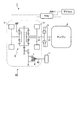
この駆動システム1は、例えば、車両10のハイブリッドシステムに適用される(図1参照)。駆動システム1は、動力源としてのエンジン2および複数のモータ・ジェネレータ3、3と、伝達系としてのトランスミッション4およびダンパ機構5と、制御系6とを有する。エンジン2は、例えば、ガソリンエンジンやディーゼルエンジンなどのレシプロタイプの内燃機関である。モータ・ジェネレータ3は、例えば、永久磁石型同期電動機などの発電機能を有する電動機である。モータ・ジェネレータ3は、トランスミッション4の入力軸(インプットシャフト)41側に連結される。なお、この実施例では、複数のモータ・ジェネレータ3が車両10の前輪および後輪に対してそれぞれ割り当てられている。
[Drive system]
The drive system 1 is applied to, for example, a hybrid system of the vehicle 10 (see FIG. 1). The drive system 1 includes an
トランスミッション4は、例えば、無段変速機であり、入力軸41側にてエンジン2およびモータ・ジェネレータ3にそれぞれ連結され、出力軸42側にてディファレンシャル7を介して車両10の車輪11に連結される。ダンパ機構5は、例えば、トーショナル・ダンパあるいはトランスミッション・ダンパである。このダンパ機構5は、エンジン2の出力軸21とトランスミッション4の入力軸41とを連結して、これらの軸21、31間のトルク振動を減衰する。また、ディファレンシャル7と車輪11とは、クラッチ機構8を介して連結される。
The
制御系6は、ECU(Electronic Control Unit)61と、各種センサ(図示省略)とを有する。各種センサには、例えば、エンジン回転数Neを検出するセンサ、モータ・ジェネレータ3の回転数Nmを検出するセンサ(例えば、レゾルバ)、アクセル開度を検出するセンサ、ブレーキセンサなどが含まれる。この制御系6では、ECU6が各センサの出力値に基づいて後述する制振制御を行う。
The
この駆動システム1は、(1)エンジン2の動力を機械的に車輪11に伝えて走行するモード(エンジン走行モード)、(2)エンジン2を停止させてモータ・ジェネレータ3の動力のみで電気自動車として走行するモード(モータ走行モード)、(3)エンジン2の動力とモータ・ジェネレータ3の動力とを併用して走行するモード(モータ・アシストモード)、(4)エンジン2の動力で発電を行いモータ・ジェネレータ3の動力により走行するモード(発電モード)、(5)車両の走行慣性力によってモータ・ジェネレータ3を駆動して発電を行うモード(回生モード)、(6)停止状態のエンジン2をモータ・ジェネレータ3の動力により駆動して始動させるモード(始動モード)などを行い得る。
The drive system 1 includes (1) a mode in which the power of the
例えば、(1)エンジン走行モードでは、エンジン2の動力がダンパ機構5を介してトランスミッション4の入力軸41に入力され、トランスミッション4の出力軸42からディファレンシャル7を介して車輪11に伝達される。また、(2)モータ走行モードでは、モータ・ジェネレータ3の動力がトランスミッション4の入力軸41に入力され、トランスミッション4の出力軸42からディファレンシャル7を介して車輪11に伝達される。
For example, (1) in the engine travel mode, the power of the
[トルク変動に対する制振制御]
一般に、車両走行時には、エンジンの出力トルクが周期的に変動する。このため、このトルク変動に起因して、エンジン回転数(エンジン2の出力軸21の回転数)Neとトランスミッション4のインプット回転数(入力軸41の回転数)と間に差が生じる。かかる回転数差は、車両の振動発生の原因になる。
[Vibration control for torque fluctuation]
Generally, when the vehicle travels, the output torque of the engine fluctuates periodically. For this reason, due to this torque fluctuation, there is a difference between the engine rotational speed (the rotational speed of the
また、波状路や悪路の走行時には、タイヤのスリップグリップなどの路面入力により、トランスミッション4の入力軸41にトルクが負荷される。すると、エンジン回転数Neとトランスミッションのインプット回転数との間に差が生じて、振動発生の原因となる。特に、かかる路面入力によりトランスミッションに大きなトルクが負荷されると、トランスミッションが破損するおそれがある。
Further, when traveling on a wavy road or a rough road, torque is applied to the
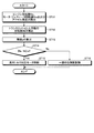
そこで、この駆動システム1では、かかるトルク変動に起因する振動を抑制するために、以下の制御が行われる(図2参照)。まず、エンジン2の回転数Ne、モータ・ジェネレータ3の回転数Nmおよびアクセル開度が検出される(ST11)。これらは、制御系6の各センサの出力値として取得される。次に、モータ・ジェネレータ3の回転数Nmに基づいて、トランスミッション4の入力軸41の回転数Ntが算出される(ST12)。
Therefore, in the drive system 1, the following control is performed in order to suppress the vibration caused by the torque fluctuation (see FIG. 2). First, the rotational speed Ne of the
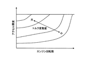
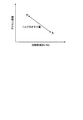
次に、エンジン2の回転数Neおよびアクセル開度に基づいて、所定の閾値aが算出される(ST13)(図3参照)。この閾値aは、エンジン2の回転数Neとトランスミッション4の入力軸41の回転数Ntとの差|Ne−Nt|に関する閾値である。なお、この閾値aは、エンジン2の回転数Neおよびアクセル開度に対するエンジン2の出力軸21のトルク変動量(回転数の変動量)と関係を有する(図4参照)。例えば、エンジン回転数Neが小さくアクセル開度が大きいときは、エンジン2の出力軸21のトルク変動量が大きいため、大きな閾値aが用いられる。また、エンジン回転数Neが大きくアクセル開度が小さいときは、エンジン2の出力軸21のトルク変動量が小さいため、小さい閾値aが用いられる。
Next, a predetermined threshold value a is calculated based on the rotational speed Ne of the
次に、エンジン2の回転数Neとトランスミッション4の入力軸41の回転数Ntと閾値aとが|Ne−Nt|>aの関係を有するか否かが判定される(ST14)。すなわち、ダンパ機構5におけるエンジン2の出力軸21とトランスミッション4の入力軸41との回転数差|Ne−Nt|が所定の閾値aよりも大きいか否かが判定される。
Next, it is determined whether or not the rotational speed Ne of the
ここで、判定ステップST14にて|Ne−Nt|>aの関係が満たされると判定された場合には、エンジン2の出力軸21とトランスミッション4の入力軸41との回転数差|Ne−Nt|が過大となっており、振動が発生し易い状況にある。そこで、かかる場合には、モータ・ジェネレータ3が駆動されて、ダンパ機構5におけるトルク変動を減衰させるための制振トルクを発生する(過大トルク対応モータ制御)(ST15)。具体的には、モータ・ジェネレータ3が逆位相の制振トルクを発生して、エンジン2の出力軸21とトランスミッション4の入力軸41との回転数差|Ne−Nt|を減少させる。これにより、過大トルクの発生が抑制されて、トルク振動が抑制される。また、これにより、ドライブラインの強度および信頼性が向上し、また、装置の小型化が可能となる利点がある。
If it is determined in the determination step ST14 that the relationship | Ne−Nt |> a is satisfied, the rotational speed difference between the
一方、判定ステップST14にて|Ne−Nt|>aの関係が満たされないと判定された場合には、エンジン2の出力軸21とトランスミッション4の入力軸41との回転数差|Ne−Nt|が比較的小さい状況にある。そこで、かかる場合には、一般的な制振制御が行われる(ST16)。例えば、エンジン2の周期的な出力トルクの変動を抑制するための制振制御が行われる。かかる制振制御には、公知のものが採用され得る。なお、この一般的な制振制御(ST16)は、省略されても良い。
On the other hand, when it is determined in the determination step ST14 that the relationship | Ne−Nt |> a is not satisfied, the rotational speed difference between the
[効果]
以上説明したように、この駆動システム1では、エンジン2の出力軸21とトランスミッション4の入力軸41との回転数差|Ne−Nt|が所定の閾値aよりも大きいときに、モータ・ジェネレータ3が制振トルクを発生して制振制御が行われる(図2参照)。かかる構成では、例えば、路面入力などに起因する過大トルク(エンジン2の周期的なトルク変動よりも大きなトルク)が作用したときに、この過大トルクに対して適切な制振制御が行われる。これにより、トランスミッション4への過負荷が効果的に抑制されるので、トルク振動が効果的に抑制される利点がある。また、このとき、エンジン2の回転数Neとアクセル開度との相関性を考慮して算出された閾値aが用いられるので、必要な場面でのみ制振制御が行われる。これにより、制振制御の実行によるモータ・ジェネレータ3の損失が低減されるので、燃費が向上する利点がある。例えば、車両走行時にて常にモータ・ジェネレータを駆動して逆位相の制振トルクを発生させるとすると、モータ・ジェネレータの負荷が増加して損失が発生する問題がある。したがって、トランスミッションの破損につながるような大きなトルク負荷が生じたときのみ、モータ・ジェネレータを駆動して制振トルクを発生させることにより、効率的な運転が可能となる。
[effect]
As described above, in the drive system 1, when the rotational speed difference | Ne−Nt | between the
なお、この駆動システム1では、閾値aは、エンジン回転数Neが大きく且つアクセル開度が小さい領域にて小さく設定され、エンジン回転数Neが小さく且つアクセル開度が大きい領域にて小さく設定されることが好ましい(図3参照)。かかる構成では、エンジン回転数Neおよびアクセル開度の相対関係によって閾値aが適正化されるので、ドライバーの違和感が低減される利点がある。 In this drive system 1, the threshold value a is set to be small in a region where the engine speed Ne is large and the accelerator opening is small, and is set small in a region where the engine speed Ne is small and the accelerator opening is large. It is preferable (see FIG. 3). In such a configuration, since the threshold value a is optimized by the relative relationship between the engine speed Ne and the accelerator opening, there is an advantage that the driver's uncomfortable feeling is reduced.
すなわち、エンジン回転数Neが大きくアクセル開度が小さい領域では、エンジン2の出力トルクの変動が小さくドライバーの要求駆動力が小さい。したがって、閾値aが小さく設定されることにより、トルク変動に対する制振制御が積極的に行われる。一方、エンジン回転数Neが小さくアクセル開度が大きい領域では、エンジン2の出力トルクの変動が大きくドライバーの要求駆動力が大きい。したがって、閾値aが大きく設定されることにより、トルク変動に対する制振制御が適正に行われる。
That is, in a region where the engine speed Ne is large and the accelerator opening is small, the output torque fluctuation of the
[変形例]
また、この駆動システム1では、|Ne−Nt|>aかつ加速運転時にて、エンジン2の出力トルクが引き下げられることが好ましい。外部から過大トルクが入力されると、トランスミッション4には、この過大トルクとエンジントルクとの双方が作用する。したがって、|Ne−Nt|>aかつ加速運転時にてエンジンが出力トルクを引き下げることにより、トランスミッションに作用する負荷トルクが軽減される。これにより、車両の振動が効果的に抑制される利点がある。なお、過大トルクが発生するような運転条件下(|Ne−Nt|>a)では、波状路や石畳路などの特殊環境での走行状態であることが多い。したがって、かかる運転条件下にてエンジンの出力トルクを引き下げたとしても、ドライバーの違和感は少ない。なお、加速運転時か否かの判定は、アクセル開度センサの出力値などに基づいてECU61により行われる。
[Modification]
Further, in the drive system 1, it is preferable that the output torque of the
また、上記の構成では、エンジン2の出力トルクの引き下げ量が回転数差|Ne−Nt|およびアクセル開度に比例して設定されることが好ましい(図6参照)。かかる構成では、エンジン2の出力トルクの引き下げ量が外部入力の大きさ(回転数差|Ne−Nt|)とドライバー要求による駆動力(アクセル開度)とに比例して設定されるので、ドライバーの違和感が低減される利点がある。
In the above configuration, it is preferable that the output torque reduction amount of the
例えば、回転数差|Ne−Nt|が大きくアクセル開度が小さいときは、エンジン2の出力トルクの引き下げ量が大きく設定される(図6参照)。この運転条件下では、トルク変動が小さくドライバーの要求駆動力が小さい。したがって、エンジン2の出力トルクを大きく引き下げ得る。また、回転数差|Ne−Nt|が小さくアクセル開度が大きいときは、エンジン2の出力トルクの引き下げ量が小さく設定される。この運転条件下では、トルク変動が小さくドライバーの要求駆動力が大きい。したがって、エンジン2の出力トルクの引き下げ量を小さく設定する。
For example, when the rotational speed difference | Ne−Nt | is large and the accelerator opening is small, the output torque reduction amount of the
また、上記の構成では、エンジン2の出力トルクの引き下げ時にて、エンジン2の回転数Neが増加されると共にトランスミッション4の変速比がエンジン2の実駆動力を一定とする設定に変更されることが好ましい。かかる構成では、エンジン2の出力トルクの引き下げ時にて、エンジン2の回転数Neが増加されることによりエンジン2の出力トルクが維持され、また、トランスミッション4の変速比が変更される。これにより、エンジン2の実駆動力が一定に維持されるので、ドライバーの要求駆動力が適正に確保される利点がある。
In the above configuration, when the output torque of the
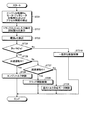
例えば、この実施例の変形例では、トルク変動に対する制振制御が以下のように行われても良い(図5参照)。なお、図2と図5とでは、ステップST11〜ST14とステップST21〜ST24とがそれぞれ対応する。また、ステップST15とステップST29とが対応し、また、ステップST16とステップST210とが対応する。したがって、これらの説明については、省略する。 For example, in a modification of this embodiment, vibration suppression control for torque fluctuation may be performed as follows (see FIG. 5). 2 and 5 correspond to steps ST11 to ST14 and steps ST21 to ST24, respectively. Further, step ST15 and step ST29 correspond to each other, and step ST16 and step ST210 correspond to each other. Therefore, these descriptions are omitted.
この制振制御では、まず、エンジン回転数Ne、モータ・ジェネレータ3の回転数Nmおよびアクセル開度が検出される(ST21)。次に、トランスミッション4の入力軸41の回転数Ntが算出される(ST22)。次に、エンジン回転数Neとアクセル開度とに基づいて閾値aが算出される(ST23)。次に、エンジン2の回転数Neとトランスミッション4の入力軸41の回転数Ntと閾値aとが|Ne−Nt|>aの関係を有するか否かが判定される(ST24)。
In this vibration suppression control, first, the engine rotational speed Ne, the rotational speed Nm of the motor /
そして、判定ステップST24にて|Ne−Nt|>aの関係が満たされると判定された場合には、アクセル開度センサの出力値に基づいて、加速運転中か否かが判定される(ST25)。そして、加速運転中であると判定された場合には、エンジン2の出力トルクが引き下げられる(エンジントルク制御)(ST26)。また、このとき、エンジン2の出力トルクの引き下げ量が回転数差|Ne−Nt|およびアクセル開度に比例して設定される。これにより、過負荷となり易い運転条件下にて、トランスミッション4に作用する負荷トルクが軽減される。また、同時に、エンジン2の出力トルクの引き下げ時にて、エンジン回転数Neが増加されてエンジンの出力トルクが維持される。そして、トランスミッション4の変速比が変更されることにより、エンジン2の実駆動力が一定に維持される。
When it is determined in the determination step ST24 that the relationship | Ne−Nt |> a is satisfied, it is determined whether or not the acceleration operation is being performed based on the output value of the accelerator opening sensor (ST25). ). If it is determined that the acceleration operation is being performed, the output torque of the
また、判定ステップST25にて、加速運転中であると判定されなかった場合には、減速運転中であるか否かの判定が行われる(ST27)。この判定は、ブレーキセンサの出力値に基づいてECU61により行われる。そして、減速運転中であると判定された場合には、トランスミッション4(ディファレンシャル7)と車輪11との間のクラッチ機構8が開放操作されて、エンジン2から車輪11への動力伝達が遮断される(クラッチ開放制御ST28)。すると、トランスミッション4に過大トルクが負荷されたとき(判定ステップST24にて|Ne−Nt|>aと判定されたとき)に、車輪11からトランスミッション4への外力の入力が遮断される。これにより、トルク変動に対する制振制御が適正に行われる。なお、トランスミッション4がクラッチ機構を有する変速機を備える構成には、クラッチ機構を新たに設置する必要がないため、システムの低コストかが可能である。
If it is not determined in the determination step ST25 that the acceleration operation is being performed, it is determined whether or not the deceleration operation is being performed (ST27). This determination is made by the
なお、判定ステップST27にて、減速運転中であると判定されなかった場合には、上記した過大トルク対応モータ制御(ST15)が行われる(ST29)。また、判定ステップST24にて|Ne−Nt|>aの関係が満たされないと判定された場合には、上記した一般的な制振制御(ST16)が行われる(ST210)。 If it is not determined in the determination step ST27 that the vehicle is decelerating, the above-described excessive torque motor control (ST15) is performed (ST29). If it is determined in the determination step ST24 that the relationship | Ne−Nt |> a is not satisfied, the above-described general vibration suppression control (ST16) is performed (ST210).
以上のように、この発明にかかる駆動システムは、トルク変動に対する振動制御を適正に行い得る点で有用である。 As described above, the drive system according to the present invention is useful in that vibration control with respect to torque fluctuation can be appropriately performed.
1 駆動システム
2 エンジン
21 出力軸
3 モータ・ジェネレータ
4 トランスミッション
41 入力軸
42 出力軸
5 ダンパ機構
6 制御系
7 ディファレンシャル
8 クラッチ機構
10 車両
11 車輪
DESCRIPTION OF SYMBOLS 1
Claims (5)
前記エンジンの回転数Neと、前記モータ・ジェネレータの回転数に基づいて算出された前記トランスミッションの入力軸の回転数Ntと、前記エンジンの回転数Neおよびアクセル開度に基づいて算出された閾値aとが|Ne−Nt|>aの関係を有するときに、前記モータ・ジェネレータが前記制振トルクを発生することを特徴とする駆動システム。 An engine and a motor / generator; a transmission coupled to the engine and the motor / generator; and a damper mechanism disposed between an output shaft of the engine and an input shaft of the transmission to attenuate torque fluctuation between the shafts. And a drive system in which the motor / generator generates damping torque to attenuate torque fluctuations in the damper mechanism,
The engine speed Ne, the transmission input shaft speed Nt calculated based on the motor / generator speed, the engine speed Ne, and the threshold value a calculated based on the accelerator opening. And the motor / generator generates the damping torque when they have a relationship of | Ne−Nt |> a.
Priority Applications (1)
| Application Number | Priority Date | Filing Date | Title |
|---|---|---|---|
| JP2008322637A JP5309959B2 (en) | 2008-12-18 | 2008-12-18 | Drive system |
Applications Claiming Priority (1)
| Application Number | Priority Date | Filing Date | Title |
|---|---|---|---|
| JP2008322637A JP5309959B2 (en) | 2008-12-18 | 2008-12-18 | Drive system |
Publications (2)
| Publication Number | Publication Date |
|---|---|
| JP2010143398A true JP2010143398A (en) | 2010-07-01 |
| JP5309959B2 JP5309959B2 (en) | 2013-10-09 |
Family
ID=42564276
Family Applications (1)
| Application Number | Title | Priority Date | Filing Date |
|---|---|---|---|
| JP2008322637A Expired - Fee Related JP5309959B2 (en) | 2008-12-18 | 2008-12-18 | Drive system |
Country Status (1)
| Country | Link |
|---|---|
| JP (1) | JP5309959B2 (en) |
Cited By (4)
| Publication number | Priority date | Publication date | Assignee | Title |
|---|---|---|---|---|
| JP2012097709A (en) * | 2010-11-05 | 2012-05-24 | Toyota Motor Corp | Control device of vehicle |
| JP2013035314A (en) * | 2011-08-03 | 2013-02-21 | Toyota Motor Corp | Controller of hybrid vehicle |
| US8868277B2 (en) | 2010-11-04 | 2014-10-21 | Toyota Jidosha Kabushiki Kaisha | Vehicular hybrid drive system |
| WO2021164812A1 (en) * | 2020-02-20 | 2021-08-26 | Schaeffler Technologies AG & Co. KG | Method for controlling a hybrid drive train |
Citations (7)
| Publication number | Priority date | Publication date | Assignee | Title |
|---|---|---|---|---|
| JPS6236934U (en) * | 1985-08-23 | 1987-03-04 | ||
| JPH1189008A (en) * | 1997-09-12 | 1999-03-30 | Honda Motor Co Ltd | Engine vibration suppressing equipment |
| JP2000032607A (en) * | 1998-07-09 | 2000-01-28 | Toyota Motor Corp | Drive system vibration suppression device for hybrid vehicle |
| JP2001136605A (en) * | 1999-11-01 | 2001-05-18 | Toyota Motor Corp | Drive device vibration suppression device |
| JP2002262408A (en) * | 2001-02-28 | 2002-09-13 | Jatco Ltd | Parallel hybrid vehicle |
| JP2007261415A (en) * | 2006-03-28 | 2007-10-11 | Mitsubishi Fuso Truck & Bus Corp | Control device for hybrid vehicle |
| JP2008195207A (en) * | 2007-02-13 | 2008-08-28 | Toyota Motor Corp | Drive device for hybrid vehicle |
-
2008
- 2008-12-18 JP JP2008322637A patent/JP5309959B2/en not_active Expired - Fee Related
Patent Citations (7)
| Publication number | Priority date | Publication date | Assignee | Title |
|---|---|---|---|---|
| JPS6236934U (en) * | 1985-08-23 | 1987-03-04 | ||
| JPH1189008A (en) * | 1997-09-12 | 1999-03-30 | Honda Motor Co Ltd | Engine vibration suppressing equipment |
| JP2000032607A (en) * | 1998-07-09 | 2000-01-28 | Toyota Motor Corp | Drive system vibration suppression device for hybrid vehicle |
| JP2001136605A (en) * | 1999-11-01 | 2001-05-18 | Toyota Motor Corp | Drive device vibration suppression device |
| JP2002262408A (en) * | 2001-02-28 | 2002-09-13 | Jatco Ltd | Parallel hybrid vehicle |
| JP2007261415A (en) * | 2006-03-28 | 2007-10-11 | Mitsubishi Fuso Truck & Bus Corp | Control device for hybrid vehicle |
| JP2008195207A (en) * | 2007-02-13 | 2008-08-28 | Toyota Motor Corp | Drive device for hybrid vehicle |
Cited By (7)
| Publication number | Priority date | Publication date | Assignee | Title |
|---|---|---|---|---|
| US8868277B2 (en) | 2010-11-04 | 2014-10-21 | Toyota Jidosha Kabushiki Kaisha | Vehicular hybrid drive system |
| JP2012097709A (en) * | 2010-11-05 | 2012-05-24 | Toyota Motor Corp | Control device of vehicle |
| JP2013035314A (en) * | 2011-08-03 | 2013-02-21 | Toyota Motor Corp | Controller of hybrid vehicle |
| WO2021164812A1 (en) * | 2020-02-20 | 2021-08-26 | Schaeffler Technologies AG & Co. KG | Method for controlling a hybrid drive train |
| CN114901532A (en) * | 2020-02-20 | 2022-08-12 | 舍弗勒技术股份两合公司 | Method for controlling a hybrid drive train |
| US11958472B2 (en) | 2020-02-20 | 2024-04-16 | Schaeffler Technologies AG & Co. KG | Method for controlling a hybrid drive train |
| CN114901532B (en) * | 2020-02-20 | 2026-01-02 | 舍弗勒技术股份两合公司 | Methods for controlling hybrid powertrains |
Also Published As
| Publication number | Publication date |
|---|---|
| JP5309959B2 (en) | 2013-10-09 |
Similar Documents
| Publication | Publication Date | Title |
|---|---|---|
| JP4805624B2 (en) | A method of damping main power source vibration in a hybrid vehicle powertrain. | |
| JP3803269B2 (en) | Parallel hybrid vehicle | |
| KR101628545B1 (en) | The regenerative braking control method of the hybrid vehicle | |
| CN105189169B (en) | drive unit for vehicle | |
| JP2011098709A (en) | Anti-jerk control apparatus and method for hybrid vehicle | |
| JP7540659B2 (en) | Vehicle control device | |
| JP2009220712A (en) | Clutch transmission torque controller for hybrid car | |
| WO2011155024A1 (en) | Control device for vehicle and control method for vehicle | |
| US20230400094A1 (en) | Control device and control method of electric vehicle | |
| JP7006532B2 (en) | Torque control device | |
| WO2010143030A1 (en) | Control apparatus and control method for vehicle | |
| JP5309959B2 (en) | Drive system | |
| JP5239841B2 (en) | Control device for hybrid vehicle | |
| JP2010274875A (en) | Vibration control device for hybrid vehicle | |
| JP4569266B2 (en) | Vehicle motor traction control device | |
| JP4710299B2 (en) | Vehicle motor traction control device | |
| CN112368172B (en) | control device | |
| JP5867109B2 (en) | Control device for hybrid vehicle | |
| JP3374752B2 (en) | Drive system vibration suppression device for hybrid vehicle | |
| WO2015019399A1 (en) | Vehicle vibration suppression control device | |
| JP6870622B2 (en) | Electric vehicle control device | |
| JP5850609B2 (en) | Control device for hybrid vehicle | |
| JP4816243B2 (en) | VEHICLE POWER DEVICE AND CONTROL DEVICE THEREOF | |
| JP2007112248A (en) | Vibration control device for drive train | |
| JP4604687B2 (en) | Vehicle control device |
Legal Events
| Date | Code | Title | Description |
|---|---|---|---|
| A621 | Written request for application examination |
Free format text: JAPANESE INTERMEDIATE CODE: A621 Effective date: 20110629 |
|
| A131 | Notification of reasons for refusal |
Free format text: JAPANESE INTERMEDIATE CODE: A131 Effective date: 20121009 |
|
| A521 | Request for written amendment filed |
Free format text: JAPANESE INTERMEDIATE CODE: A523 Effective date: 20121204 |
|
| A02 | Decision of refusal |
Free format text: JAPANESE INTERMEDIATE CODE: A02 Effective date: 20130205 |
|
| A521 | Request for written amendment filed |
Free format text: JAPANESE INTERMEDIATE CODE: A523 Effective date: 20130507 |
|
| A911 | Transfer to examiner for re-examination before appeal (zenchi) |
Free format text: JAPANESE INTERMEDIATE CODE: A911 Effective date: 20130514 |
|
| TRDD | Decision of grant or rejection written | ||
| A01 | Written decision to grant a patent or to grant a registration (utility model) |
Free format text: JAPANESE INTERMEDIATE CODE: A01 Effective date: 20130604 |
|
| A61 | First payment of annual fees (during grant procedure) |
Free format text: JAPANESE INTERMEDIATE CODE: A61 Effective date: 20130617 |
|
| R151 | Written notification of patent or utility model registration |
Ref document number: 5309959 Country of ref document: JP Free format text: JAPANESE INTERMEDIATE CODE: R151 |
|
| LAPS | Cancellation because of no payment of annual fees |