JP2010143333A - Front pillar - Google Patents
Front pillar Download PDFInfo
- Publication number
- JP2010143333A JP2010143333A JP2008321299A JP2008321299A JP2010143333A JP 2010143333 A JP2010143333 A JP 2010143333A JP 2008321299 A JP2008321299 A JP 2008321299A JP 2008321299 A JP2008321299 A JP 2008321299A JP 2010143333 A JP2010143333 A JP 2010143333A
- Authority
- JP
- Japan
- Prior art keywords
- front pillar
- panel
- welded
- bent portion
- outer panel
- Prior art date
- Legal status (The legal status is an assumption and is not a legal conclusion. Google has not performed a legal analysis and makes no representation as to the accuracy of the status listed.)
- Withdrawn
Links
- 230000003014 reinforcing effect Effects 0.000 claims description 17
- 238000003466 welding Methods 0.000 claims description 13
- 230000002787 reinforcement Effects 0.000 abstract description 52
- 239000003351 stiffener Substances 0.000 description 8
- 229910000831 Steel Inorganic materials 0.000 description 5
- 239000010959 steel Substances 0.000 description 5
- 238000005452 bending Methods 0.000 description 3
- 239000000470 constituent Substances 0.000 description 2
- 230000015572 biosynthetic process Effects 0.000 description 1
- 230000000694 effects Effects 0.000 description 1
Images
Landscapes
- Body Structure For Vehicles (AREA)
Abstract
Description
この発明は、車両のフロントピラーに係り、特に、バスなどの大型車両の前方ドアの前側に配置されたフロントピラーに関する。 The present invention relates to a front pillar of a vehicle, and more particularly, to a front pillar disposed on the front side of a front door of a large vehicle such as a bus.
従来、車両のフロントピラーとして、補強のためのリンフォースメントパネルを用いる代わりに、フロントピラーインナーパネルをその長手方向に沿って2分割して、その分割した部位同士を重ねてスポット溶接した構造を有するフロントピラーが知られている(例えば、特許文献1参照。)。これにより、フロントピラーの内壁にリンフォースメントパネルを重ねて溶接した場合と同様の効果が得られ、フロントピラーの剛性を高めることができる。また、この構造を採用すると、リンフォースメントパネルを省略した分だけフロントピラーを軽量化でき、車両の軽量化に貢献できる。
しかし、上述した特許文献1のフロントピラーにおいては、2分割したインナーパネルをそれぞれフロントピラーの閉断面形状に合せて折り曲げて、この折り曲げた部位同士を重ねてスポット溶接しているため、折り曲げ部において2枚のパネル間に微小なすき間が形成されてしまう。このすき間は溶接されないため、例えばねじれ応力が集中してパネルに亀裂を生じ易い。 However, in the front pillar of Patent Document 1 described above, the inner panel divided into two parts is bent according to the closed cross-sectional shape of the front pillar, and the bent parts are overlapped and spot welded. A minute gap is formed between the two panels. Since the gap is not welded, for example, the torsional stress is concentrated and the panel is likely to crack.
この発明の目的は、特に折り曲げ部の剛性が高いフロントピラーを提供することにある。 An object of the present invention is to provide a front pillar having a particularly high bending portion rigidity.
上記目的を達成するため、この発明のフロントピラーは、内面に補強板を溶接したパイプ状に形成され、上記補強板が、上記フロントピラーの断面形状に合せて折り曲げられた折り曲げ部を有するとともに、この折り曲げ部に沿ったスリットを有し、このスリットを介して上記フロントピラーの内面に隅肉溶接されている。 In order to achieve the above object, the front pillar of the present invention is formed in a pipe shape in which a reinforcing plate is welded to the inner surface, and the reinforcing plate has a bent portion that is bent in accordance with the cross-sectional shape of the front pillar, A slit is provided along the bent portion, and fillet welded to the inner surface of the front pillar through the slit.
また、この発明のフロントピラーは、上下方向に延びた折り曲げ部を有するフロントピラーアウターパネルのフランジ部とフロントピラーインナーパネルのフランジ部を溶接して、このパイプ状のフロントピラーアウターパネルおよびフロントピラーインナーパネルの内面に補強板を接触せしめて溶接したフロントピラーであって、上記補強板は、上記フロントピラーアウターパネルの上記折り曲げ部に沿って折り曲げされた折り曲げ部、およびこの折り曲げ部に沿って形成された少なくとも1つのスリットを有し、このスリットを介して上記フロントピラーアウターパネルの折り曲げ部の内側に隅肉溶接される。 Further, the front pillar of the present invention welds the flange portion of the front pillar outer panel having the bent portion extending in the vertical direction and the flange portion of the front pillar inner panel so that the pipe-shaped front pillar outer panel and front pillar inner panel are welded. A front pillar that is welded by bringing a reinforcing plate into contact with the inner surface of the panel, wherein the reinforcing plate is formed along the bent portion of the front pillar outer panel, and the bent portion is formed along the bent portion. In addition, at least one slit is provided, and fillet welded to the inside of the bent portion of the front pillar outer panel through the slit.
上記発明によると、補強板の折り曲げ部に形成したスリットを介して、補強板をフロントピラーの内面に隅肉溶接するようにしたため、2枚のプレートが重なった折り曲げ部のすき間を溶接で埋めることができ、この溶接部分の板厚を厚くすることができ、折り曲げ部の剛性を高めることができる。これにより、例えば、フロントピラーにねじれ応力が加わった場合など、フロントピラーの折り曲げ部に応力が集中することを防止でき、折り曲げ部近くで亀裂を生じる不具合を防止できる。 According to the above invention, since the reinforcing plate is fillet welded to the inner surface of the front pillar through the slit formed in the bent portion of the reinforcing plate, the gap of the bent portion where the two plates overlap is filled by welding. The thickness of the welded portion can be increased, and the rigidity of the bent portion can be increased. As a result, for example, when a torsional stress is applied to the front pillar, it is possible to prevent the stress from being concentrated on the bent portion of the front pillar, and it is possible to prevent a problem that a crack occurs near the bent portion.
(請求項1)この発明によると、フロントピラーの折り曲げ部の剛性を高めることができる。 (Claim 1) According to the present invention, the rigidity of the bent portion of the front pillar can be increased.
(請求項2)この発明によると、フロントピラーアウターパネルの折り曲げ部の剛性を高めることができ、フロントピラーの剛性を高めることができる。 (Claim 2) According to the present invention, the rigidity of the bent portion of the front pillar outer panel can be increased, and the rigidity of the front pillar can be increased.
(請求項3)この発明によると、補強板を設けない場合と比較して折り曲げ部に作用する応力を半分未満にできる。 (Claim 3) According to the present invention, the stress acting on the bent portion can be reduced to less than half compared with the case where the reinforcing plate is not provided.
(請求項4)この発明によると、栓溶接によって応力集中が緩和され、補強板とフロントピラーアウターパネルとの間の密着性、および補強板とフロントピラーインナーパネルとの間の密着性を良好にでき、ねじれ負荷に対する剛性を高めることができる。 (Claim 4) According to the present invention, stress concentration is mitigated by plug welding, and adhesion between the reinforcing plate and the front pillar outer panel and adhesion between the reinforcing plate and the front pillar inner panel are improved. It is possible to increase the rigidity against torsional load.
以下、図面を参照しながらこの発明の実施の形態について詳細に説明する。
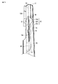
図1は、この発明の実施の形態に係る車両の一例としてのバスの車体フレーム1を左側から見た側面概略図である。
Hereinafter, embodiments of the present invention will be described in detail with reference to the drawings.
FIG. 1 is a schematic side view of a body frame 1 of a bus as an example of a vehicle according to an embodiment of the present invention as viewed from the left side.
このバスは、前方左側に前方ドア(図示せず)のための開口部2を有する。車体フレーム1は、この開口部2の前側にフロントピラー10を有する。フロントピラー10は、後に詳述するように、フロントピラーアウターパネル12、フロントピラーインナーパネル14、およびリンフォースメントパネル16(補強板)を有するパイプ状に形成されている。このフロントピラー10は、車体の略全高にわたって略鉛直上下方向に延設されている。
This bus has an
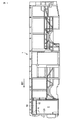
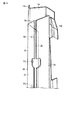
図2には、図1のフロントピラー10の上端部付近の領域Rを部分的に拡大した部分拡大斜視図を示してある。図2では、フロントピラー10のフロントピラーインナーパネル14の図示を省略してあり、フロントピラーアウターパネル12のみを図示してある。
FIG. 2 is a partially enlarged perspective view in which the region R in the vicinity of the upper end portion of the
これによると、フロントピラーアウターパネル12の車両後方側の面12aには、上述した開口部2の上端側に配置されたスチフナ18の端部18aが突き当てられている。そして、このスチフナ18の前方端部18aがフロントピラーアウターパネル12の後方面12aに溶接Wされている。また、スチフナ18の上方には、鋼板19(図1)が取り付けられている。
According to this, the end portion 18a of the
このスチフナ18は、フロントピラー10とともに、前方ドアのための比較的大きな開口部2の周囲に設けられるため、車両走行時に車体フレーム1にねじれを生じた際に、スチフナ18の端部18aとフロントピラーアウターパネル12の後方面12aとの間の溶接部分Wに比較的大きなねじれ応力が作用する。このとき、フロントピラー10側の剛性が低いとフロントピラー10に亀裂を生じてしまう場合がある。
Since this
このため、一般に、スチフナ18が当接されるフロントピラー10の部位には、補強板としてのリンフォースメントパネル16(図3)が取り付けられる。リンフォースメントパネル16は、フロントピラーアウターパネル12の折り曲げ部12bに合せて折り曲げされた折り曲げ部22(後述する)を有し、フロントピラーアウターパネル12の内面側に溶接される。このように、2枚の折り曲げた鋼板を重ねて溶接すると、折り曲げ部12b、22の間にすき間が形成される。
For this reason, a reinforcement panel 16 (FIG. 3) as a reinforcing plate is generally attached to a portion of the
つまり、リンフォースメントパネル16をフロントピラーアウターパネル12に溶接して補強しても、折り曲げ部にすき間が形成されてしまうため、この部位の剛性が不十分になる。特に、上述したようにスチフナ18が当接されて溶接される部位では、ねじれ応力が集中するため、この折り曲げ部12bにおいて亀裂を生じる可能性がある。
That is, even if the
よって、本実施の形態では、この折り曲げ部12b、22の剛性を高めるため、リンフォースメントパネル16の折り曲げ部22にスリット20を形成し、このスリット20を介して、リンフォースメントパネル16をフロントピラーアウターパネル12の内面に溶接するようにした。以下、本願発明のこのような特徴的な構造について、より詳細に説明する。
Therefore, in this embodiment, in order to increase the rigidity of the
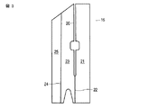
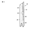
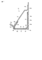
図3には、この発明の実施の形態に係るリンフォースメントパネル16の展開図を示してあり、図4には、リンフォースメントパネル16の外観斜視図を示してある。図3の展開図に示した2本の折り曲げ部22、24で紙面奥側にリンフォースメントパネル16を折り曲げると図4の状態になる。本実施の形態では、リンフォースメントパネル16の板厚を2.3mmに設計した。
FIG. 3 is a development view of the
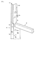
また、図5には、リンフォースメントパネル16をフロントピラーアウターパネル12の内面側に溶接した状態の外観斜視図を示してある。また、図6には、リンフォースメントパネル16をフロントピラーインナーパネル14の内面にリンフォースメントパネル16を溶接した状態の外観斜視図を示してある。さらに、図7には、リンフォースメントパネル16を内部に溶接したフロントピラー10の断面図を示してある。本実施の形態では、フロントピラーアウターパネル12およびフロントピラーインナーパネル14の板厚を1.6mmに設計した。
FIG. 5 is an external perspective view showing a state in which the
フロントピラー10は、図7に示すように、フロントピラーアウターパネル12のフランジ部12c、12dと、フロントピラーインナーパネル14のフランジ部14a、14bと、をそれぞれ溶接して、閉断面形状、すなわちパイプ状に形成されている。そして、このパイプ状の内面にリンフォースメントパネル16が溶接されている。
As shown in FIG. 7, the
フロントピラーアウターパネル12は、上述した後方面12aと車幅方向左側の面12Lとの間で折り曲げされた折り曲げ部12bを有する。この折り曲げ部12bは、上下方向に延びている。また、フロントピラーアウターパネル12は、リンフォースメントパネル16を複数個所で栓溶接するための複数の貫通した孔12eを有する。これら複数の孔12eは、図2に示すように、フロントピラーアウターパネル12の後方面12aに2列に並んで上下に離間した4箇所、すなわち合計8箇所に設けられている。
The front pillar
また、フロントピラーインナーパネル14も、リンフォースメントパネル16を複数個所で栓溶接するための複数の貫通した孔14cを有する。フロントピラーインナーパネル14の複数の孔14cは、上下に離間して1列だけ設けられている。
The front pillar
なお、フロントピラーアウターパネル12とリンフォースメントパネル16との間の栓溶接の数、およびフロントピラーインナーパネル14とリンフォースメントパネル16との間の栓溶接の数は、任意に設計可能であり、少なくとも後述するスリット20を挟んだ一側でフロントピラーアウターパネル12とリンフォースメントパネル16が少なくとも1箇所で栓溶接され、スリット20を挟んだ他側でフロントピラーインナーパネル14とリンフォースメントパネル16が少なくとも1箇所で栓溶接されれば良い。
The number of plug welds between the front pillar
一方、リンフォースメントパネル16は、図3乃至図5に示すように、フロントピラーアウターパネル12の折り曲げ部12bに合せて折り曲げされた折り曲げ部22を有する。また、リンフォースメントパネル16は、この折り曲げ部22と略平行に延びた別の折り曲げ部24を有する。この別の折り曲げ部24は、図7に示すように、フロントピラーアウターパネル12のフランジ部12cとフロントピラーインナーパネル14のフランジ部14aの溶接箇所に対向する。なお、これら折り曲げ部22、24も、上下に延びている。
On the other hand, the
リンフォースメントパネル16の上述した2箇所の折り曲げ部22、24で見かけ上区画された3つの板部21、23、25(図3に展開図を示す)は、それぞれ、図7に示すように、フロントピラーアウターパネル12の後方面12aの内面側、フロントピラーアウターパネル12の左側面12Lの内面側、およびフロントピラーインナーパネル14の内面側に面で接触するよう配置される。
As shown in FIG. 7, the three
そして、リンフォースメントパネル16の板部21に接触したフロントピラーアウターパネル12の複数の孔12eを介してリンフォースメントパネル16とフロントピラーアウターパネル12が栓溶接され、リンフォースメントパネル16の板部25に接触したフロントピラーインナーパネル14の複数の孔14cを介してリンフォースメントパネル16とフロントピラーインナーパネル14が栓溶接されて、リンフォースメントパネル16がフロントピラーアウターパネル12およびフロントピラーインナーパネル14に溶接される。
Then, the
このとき、リンフォースメントパネル16の折り曲げ部22に沿って形成されたスリット20を介して、フロントピラーアウターパネル12の折り曲げ部12bの湾曲内側面に対して隅肉溶接30がなされ、2枚の鋼板の折り曲げ部12b、22間のすき間が少なくとも部分的に埋められる。これにより、折り曲げ部12b、22における2枚の鋼板の板厚を厚くすることができ、フロントピラー10の特に折り曲げ部12bの剛性を高めることができる。
At this time, fillet welds 30 are made on the curved inner surface of the
なお、本実施の形態では、図5に示すように、スリット20の全長にわたって隅肉溶接するのではなく、3つに分割した隅肉溶接30a、30b、30cを実施したが、隅肉溶接の分割数や長さについては任意に設計可能であり、要求される剛性に応じて変更できる。また、スリット20の幅や長さ、または形成位置も、任意に設計可能であるが、作業性を考慮して、リンフォースメントパネル16の全長にわたってスリット20を形成することは好ましくない。
In this embodiment, as shown in FIG. 5, fillet welds 30 a, 30 b, and 30 c divided into three parts are performed instead of fillet welds over the entire length of the
以上のように、本実施の形態によると、リンフォースメントパネル16の折り曲げ部22に形成したスリット20を介して、フロントピラーアウターパネル12の折り曲げ部12bの内面側に隅肉溶接するようにしたため、折り曲げ部12b、22に形成されるすき間を溶接で埋めることができ、折り曲げ部における2枚の鋼板の板厚を厚くすることができ、折り曲げ部12b、22の剛性を高めることができる。
As described above, according to the present embodiment, fillet welding is performed on the inner surface side of the
特に、フロントピラーアウターパネル12に注目すると、車両走行時に車体フレーム1にねじれを生じた場合、フロントピラーアウターパネル12の折り曲げ部12bを中心にして後方面部12aと左側面部12Lとが異なる方向にねじ曲げられるため、折り曲げ部12bには高い応力集中が発生する。このため、本実施の形態のように、折り曲げ部12bの剛性を高めることが有効となる。
In particular, when attention is paid to the front pillar
また、本実施の形態では、フロントピラーアウターパネル12およびフロントピラーインナーパネル14の板厚よりリンフォースメントパネル16の板厚を厚くしたため、リンフォースメントパネル16を設けない場合と比較して、フロントピラーアウターパネル12に作用する応力を半分未満にすることができ、フロントピラー10の強度および耐久性を高めることができる。
In the present embodiment, the
なお、本実施の形態では、フロントピラーアウターパネル12およびフロントピラーインナーパネル14の板厚を1.6mmに設計して、リンフォースメントパネル16の板厚を2.3mmに設計したが、少なくともフロントピラーアウターパネル12およびフロントピラーインナーパネル14の板厚よりリンフォースメントパネル16の板厚を厚くすれば良く、厚さは任意に設定可能である。
In the present embodiment, the thickness of the front pillar
また、本実施の形態では、フロントピラーアウターパネル12およびフロントピラーインナーパネル14とリンフォースメントパネル16との間の溶接を栓溶接にしたため、フロントピラー10にねじれ応力が作用した場合、応力が栓溶接部の円周に沿って均等に伝わることになり、応力集中を緩和できる。また、栓溶接を採用したことにより、溶接量を多くでき、フロントピラーアウターパネル12およびフロントピラーインナーパネル14とリンフォースメントパネル16との間の密着性を向上させることができ、ねじれ負荷に対する協調性を良好にでき、リンフォースメントパネル16による補強効果を十分に発揮できる。
In the present embodiment, since the welding between the front pillar
なお、この発明は、上述した実施の形態そのままに限定されるものではなく、実施段階ではその要旨を逸脱しない範囲で構成要素を変形して具体化できる。また、上述した実施の形態に開示されている複数の構成要素の適宜な組み合わせにより種々の発明を形成できる。例えば、上述した実施の形態に示される全構成要素から幾つかの構成要素を削除しても良い。 Note that the present invention is not limited to the above-described embodiment as it is, and can be embodied by modifying the constituent elements without departing from the scope of the invention in the implementation stage. Various inventions can be formed by appropriately combining a plurality of constituent elements disclosed in the above-described embodiments. For example, you may delete some components from all the components shown by embodiment mentioned above.
例えば、上述した実施の形態では、フロントピラー10の内面にリンフォースメントパネル16を溶接して剛性を高めた場合について説明したが、車体フレーム1の他の全てのパイプ構造に対して本願発明を適用できる。
For example, in the above-described embodiment, the case where the
1…車体フレーム、2…開口部、10…フロントピラー、12…フロントピラーアウターパネル、14…フロントピラーインナーパネル、16…リンフォースメントパネル、18…スチフナ、20…スリット、28…、28b…、42…。 DESCRIPTION OF SYMBOLS 1 ... Body frame, 2 ... Opening part, 10 ... Front pillar, 12 ... Front pillar outer panel, 14 ... Front pillar inner panel, 16 ... Reinforcement panel, 18 ... Stiffener, 20 ... Slit, 28 ..., 28b ..., 42 ...
Claims (4)
上記補強板が、上記フロントピラーの断面形状に合せて折り曲げられた折り曲げ部を有するとともに、この折り曲げ部に沿ったスリットを有し、このスリットを介して上記フロントピラーの内面に隅肉溶接されていることを特徴とするフロントピラー。 A pipe-shaped front pillar with a reinforcing plate welded to its inner surface,
The reinforcing plate has a bent portion bent according to the cross-sectional shape of the front pillar, and has a slit along the bent portion, and fillet welded to the inner surface of the front pillar through the slit. The front pillar is characterized by
上記補強板は、上記フロントピラーアウターパネルの上記折り曲げ部に沿って折り曲げされた折り曲げ部、およびこの折り曲げ部に沿って形成された少なくとも1つのスリットを有し、このスリットを介して上記フロントピラーアウターパネルの折り曲げ部の内側に隅肉溶接されることを特徴とするフロントピラー。 The flange portion of the front pillar outer panel and the flange portion of the front pillar inner panel having bent portions extending in the vertical direction are welded, and the reinforcing plate is brought into contact with the inner surfaces of the pipe-shaped front pillar outer panel and front pillar inner panel. Welded front pillar,
The reinforcing plate has a bent portion bent along the bent portion of the front pillar outer panel, and at least one slit formed along the bent portion, and the front pillar outer through the slit. A front pillar that is fillet welded inside the bent portion of the panel.
Priority Applications (1)
| Application Number | Priority Date | Filing Date | Title |
|---|---|---|---|
| JP2008321299A JP2010143333A (en) | 2008-12-17 | 2008-12-17 | Front pillar |
Applications Claiming Priority (1)
| Application Number | Priority Date | Filing Date | Title |
|---|---|---|---|
| JP2008321299A JP2010143333A (en) | 2008-12-17 | 2008-12-17 | Front pillar |
Publications (1)
| Publication Number | Publication Date |
|---|---|
| JP2010143333A true JP2010143333A (en) | 2010-07-01 |
Family
ID=42564217
Family Applications (1)
| Application Number | Title | Priority Date | Filing Date |
|---|---|---|---|
| JP2008321299A Withdrawn JP2010143333A (en) | 2008-12-17 | 2008-12-17 | Front pillar |
Country Status (1)
| Country | Link |
|---|---|
| JP (1) | JP2010143333A (en) |
Cited By (3)
| Publication number | Priority date | Publication date | Assignee | Title |
|---|---|---|---|---|
| JP2013189173A (en) * | 2012-03-15 | 2013-09-26 | Nippon Steel & Sumitomo Metal Corp | Structural member for automobile body, and manufacturing method thereof |
| US9452787B2 (en) | 2014-06-03 | 2016-09-27 | Toyota Jidosha Kabushiki Kaisha | Vehicle front portion structure |
| EP2617509A4 (en) * | 2010-09-16 | 2016-12-21 | Nippon Steel & Sumitomo Metal Corp | MOLDED ELEMENT AND METHOD FOR MANUFACTURING THE SAME |
-
2008
- 2008-12-17 JP JP2008321299A patent/JP2010143333A/en not_active Withdrawn
Cited By (4)
| Publication number | Priority date | Publication date | Assignee | Title |
|---|---|---|---|---|
| EP2617509A4 (en) * | 2010-09-16 | 2016-12-21 | Nippon Steel & Sumitomo Metal Corp | MOLDED ELEMENT AND METHOD FOR MANUFACTURING THE SAME |
| US10035324B2 (en) | 2010-09-16 | 2018-07-31 | Nippon Steel & Sumitomo Metal Corporation | Formed member and manufacturing method thereof |
| JP2013189173A (en) * | 2012-03-15 | 2013-09-26 | Nippon Steel & Sumitomo Metal Corp | Structural member for automobile body, and manufacturing method thereof |
| US9452787B2 (en) | 2014-06-03 | 2016-09-27 | Toyota Jidosha Kabushiki Kaisha | Vehicle front portion structure |
Similar Documents
| Publication | Publication Date | Title |
|---|---|---|
| CN103249635B (en) | body side structure | |
| JP2013166474A (en) | Vehicle side section structure | |
| JP4852017B2 (en) | Body superstructure | |
| JP6574947B2 (en) | Lower body structure | |
| JP5668595B2 (en) | Rear upper end structure of the vehicle | |
| EP2412612A1 (en) | Side sill structure for automobile | |
| JP2014073769A (en) | Vehicle body structure | |
| JP2011255850A (en) | Vehicle door frame | |
| JP6052230B2 (en) | Vehicle body structure | |
| JP2010143333A (en) | Front pillar | |
| JP2011183893A (en) | Vehicle body floor structure | |
| JP2008279889A (en) | Body side structure | |
| JP6110834B2 (en) | Body side structure | |
| JP5096534B2 (en) | Car body side structure | |
| JP2018058441A (en) | Railway vehicle bone structure and side structure comprising the same | |
| JP4760676B2 (en) | Vehicle pillar structure | |
| JP5071984B2 (en) | Vehicle front structure | |
| JP5096535B2 (en) | Car body side structure | |
| JP6106878B2 (en) | Vehicle frame structure | |
| JP6094765B2 (en) | Body superstructure | |
| JP6631474B2 (en) | Vehicle rear structure | |
| WO2013121859A1 (en) | Side member structure of vehicle frame | |
| JP2016052852A (en) | Body rear structure | |
| JP4782568B2 (en) | Side plate structure of elevator car | |
| JP6794837B2 (en) | Body side structure |
Legal Events
| Date | Code | Title | Description |
|---|---|---|---|
| A300 | Withdrawal of application because of no request for examination |
Free format text: JAPANESE INTERMEDIATE CODE: A300 Effective date: 20120306 |