JP2010143130A - Liquid jet head and liquid jetting apparatus - Google Patents
Liquid jet head and liquid jetting apparatus Download PDFInfo
- Publication number
- JP2010143130A JP2010143130A JP2008324023A JP2008324023A JP2010143130A JP 2010143130 A JP2010143130 A JP 2010143130A JP 2008324023 A JP2008324023 A JP 2008324023A JP 2008324023 A JP2008324023 A JP 2008324023A JP 2010143130 A JP2010143130 A JP 2010143130A
- Authority
- JP
- Japan
- Prior art keywords
- nozzle
- pressure
- pressure generation
- gap
- connection hole
- Prior art date
- Legal status (The legal status is an assumption and is not a legal conclusion. Google has not performed a legal analysis and makes no representation as to the accuracy of the status listed.)
- Pending
Links
- 239000007788 liquid Substances 0.000 title claims abstract description 29
- 238000005192 partition Methods 0.000 claims abstract description 40
- 230000000087 stabilizing effect Effects 0.000 abstract 1
- 239000000758 substrate Substances 0.000 description 31
- 239000000463 material Substances 0.000 description 6
- 230000002411 adverse Effects 0.000 description 3
- 230000000149 penetrating effect Effects 0.000 description 3
- 239000004734 Polyphenylene sulfide Substances 0.000 description 2
- 230000015572 biosynthetic process Effects 0.000 description 2
- 230000000694 effects Effects 0.000 description 2
- 238000005530 etching Methods 0.000 description 2
- 238000004519 manufacturing process Methods 0.000 description 2
- 239000000203 mixture Substances 0.000 description 2
- 229920000069 polyphenylene sulfide Polymers 0.000 description 2
- 238000000018 DNA microarray Methods 0.000 description 1
- XUIMIQQOPSSXEZ-UHFFFAOYSA-N Silicon Chemical compound [Si] XUIMIQQOPSSXEZ-UHFFFAOYSA-N 0.000 description 1
- 239000013078 crystal Substances 0.000 description 1
- 238000006073 displacement reaction Methods 0.000 description 1
- 239000007772 electrode material Substances 0.000 description 1
- 238000010438 heat treatment Methods 0.000 description 1
- 238000002347 injection Methods 0.000 description 1
- 239000007924 injection Substances 0.000 description 1
- 239000004973 liquid crystal related substance Substances 0.000 description 1
- 239000007769 metal material Substances 0.000 description 1
- 230000002093 peripheral effect Effects 0.000 description 1
- 239000011347 resin Substances 0.000 description 1
- 229920005989 resin Polymers 0.000 description 1
- 229910052710 silicon Inorganic materials 0.000 description 1
- 239000010703 silicon Substances 0.000 description 1
- 229910001220 stainless steel Inorganic materials 0.000 description 1
- 239000010935 stainless steel Substances 0.000 description 1
- 230000009466 transformation Effects 0.000 description 1
Images
Landscapes
- Particle Formation And Scattering Control In Inkjet Printers (AREA)
Abstract
【課題】液滴の噴射特性を安定させることができる液体噴射ヘッド及び液体噴射装置を提供する。
【解決手段】液滴を噴射するノズル13と、ノズル13に接続され隔壁17によって区画された複数の圧力発生室11と、圧力発生室11内に液滴噴射のための圧力を発生させる圧力発生手段16とを具備し、隔壁17には少なくとも圧力発生室11に対応する領域に間隙部40が設けられており、間隙部40はノズル13とは異なる方向の面に設けられ且つ圧力発生室11とノズル13との接続部とは反対側の端部近傍で接続される接続孔41を介して外部と連通されている構成とする。
【選択図】図2A liquid ejecting head and a liquid ejecting apparatus capable of stabilizing the ejecting characteristics of droplets are provided.
A nozzle 13 for ejecting droplets, a plurality of pressure generating chambers 11 connected to the nozzle 13 and partitioned by a partition wall 17, and pressure generation for generating a pressure for droplet ejection in the pressure generating chamber 11 The partition wall 17 is provided with a gap 40 at least in a region corresponding to the pressure generation chamber 11, and the gap 40 is provided on a surface in a direction different from the nozzle 13 and the pressure generation chamber 11. It is set as the structure connected with the exterior through the connection hole 41 connected in the edge part vicinity on the opposite side to the connection part of the nozzle 13 and a nozzle.
[Selection] Figure 2
Description
本発明は、液滴を噴射する液体噴射ヘッド及び液体噴射装置に関し、特にノズルからインク滴を噴射するインクジェット式記録ヘッド及びインクジェット式記録装置に関する。 The present invention relates to a liquid ejecting head and a liquid ejecting apparatus that eject droplets, and more particularly, to an ink jet recording head and an ink jet recording apparatus that eject ink droplets from nozzles.
液滴を噴射する液体噴射ヘッドの代表例としては、例えば、インク滴を噴射するノズルと連通する圧力発生室の一部を振動板で構成し、この振動板を圧電素子により変形させて圧力発生室のインクを加圧してノズルからインク滴を噴射させるインクジェット式記録ヘッドが挙げられる。具体例としては、圧力室が形成される流路形成基板の一方面側にノズルが形成されたノズルプレートが接合され、流路形成基板の他方面側に振動板が接合され、圧力発生手段である圧電素子の先端が、この振動板上に設けられる島状部に当接するように設けられたものがある(例えば、特許文献1参照)。 As a typical example of a liquid ejecting head that ejects liquid droplets, for example, a part of a pressure generation chamber communicating with a nozzle that ejects ink droplets is configured by a vibration plate, and the vibration plate is deformed by a piezoelectric element to generate pressure. An ink jet recording head that pressurizes ink in a chamber and ejects ink droplets from nozzles can be used. As a specific example, a nozzle plate having nozzles formed on one side of a flow path forming substrate on which a pressure chamber is formed is bonded, and a diaphragm is bonded on the other side of the flow path forming substrate. There is one in which the tip of a certain piezoelectric element is provided so as to abut on an island-like portion provided on the diaphragm (see, for example, Patent Document 1).
このような構造のインクジェット式記録ヘッドでは、各圧力室(圧力発生室)を区画する隔壁の厚さが比較的薄い。なおノズルの高密度化に伴って隔壁の厚さはさらに薄くなる傾向にある。このため、圧電素子等の圧力発生手段によって圧力発生室内に圧力変動を生じさせると、それに伴って隔壁が変形し、隣接する圧力発生室の圧力変動に影響を及ぼしてしまうという問題がある。すなわち各圧力発生室間で、いわゆるクロストークが発生してしまい、インク滴の噴射特性を良好に維持することができないという問題がある。 In the ink jet recording head having such a structure, the partition walls defining the pressure chambers (pressure generation chambers) are relatively thin. As the nozzle density increases, the partition wall thickness tends to be further reduced. For this reason, when pressure fluctuation is generated in the pressure generating chamber by the pressure generating means such as a piezoelectric element, there is a problem that the partition wall is deformed accordingly and the pressure fluctuation in the adjacent pressure generating chamber is affected. That is, there is a problem that so-called crosstalk occurs between the pressure generation chambers, and ink droplet ejection characteristics cannot be maintained satisfactorily.
このような問題を解決するために、各インク室(圧力発生室)の間にダミー室を設け、各インク室内の相互の圧力干渉を避け、インク吐出の不安定性を解消するようにしたものがある(例えば、特許文献2参照)。
上述のような構成とすることで、各圧力発生室間の相互の圧力干渉は避けることはできるが、インク滴の噴射特性を十分に安定させることは難しい。例えば、特許文献2に記載の構成では、各ダミー室に連通する大気連通孔を設ける必要があり、この大気連通孔がノズルとインク室との接続部近傍に設けられている。このため、大気連通孔から排出された空気によって周囲(ノズルの周囲)の気流に乱れが生じてしまい、インク滴の噴射特性が不安定になってしまう虞がある。 By adopting the above-described configuration, mutual pressure interference between the pressure generation chambers can be avoided, but it is difficult to sufficiently stabilize the ejection characteristics of the ink droplets. For example, in the configuration described in Patent Document 2, it is necessary to provide an atmospheric communication hole communicating with each dummy chamber, and the atmospheric communication hole is provided in the vicinity of a connection portion between the nozzle and the ink chamber. For this reason, the air discharged from the atmosphere communication hole may disturb the surrounding airflow (around the nozzles), and the ink droplet ejection characteristics may become unstable.
なお、このような問題は、インク滴を噴射するインクジェット式記録ヘッドだけでなく、他の液滴を噴射する液体噴射ヘッドにおいても同様に存在する。 Such a problem exists not only in an ink jet recording head that ejects ink droplets but also in a liquid ejecting head that ejects other droplets.
本発明はこのような事情に鑑み、液滴の噴射特性を安定させることができる液体噴射ヘッド及び液体噴射装置を提供することを課題とする。 In view of such circumstances, it is an object of the present invention to provide a liquid ejecting head and a liquid ejecting apparatus that can stabilize the ejecting characteristics of droplets.
上記課題を解決する本発明は、液滴を噴射するノズルと、該ノズルに接続され隔壁によって区画された複数の圧力発生室と、該圧力発生室内に液滴噴射のための圧力を発生させる圧力発生手段とを具備し、前記隔壁には少なくとも前記圧力発生室に対応する領域に間隙部が設けられており、該間隙部は前記ノズルとは異なる方向の面に設けられ且つ前記圧力発生室と前記ノズルとの接続部とは反対側の端部近傍で接続される接続孔を介して外部と連通されていることを特徴とする液体噴射ヘッドにある。
かかる本発明では、隔壁に間隙部が設けられていると共にこの間隙部に接続孔が接続されていることで、隣接する圧力発生室間でのクロストークの発生を抑制することができる。すなわち隣接する圧力発生室内の圧力変動の影響を抑えて、各ノズルから良好に液滴を噴射することができる。また、ノズルから液滴を噴射する際に隔壁が変形することで、接続孔から空気が排出されて周囲の気流に乱れが生じるが、接続孔がノズルとは離れた位置に設けられていることで、この気流の乱れによる液滴の噴射特性への悪影響を抑制することができる。よって、各ノズルから噴射される液滴の噴射特性が安定する。
The present invention that solves the above-described problems includes a nozzle that ejects droplets, a plurality of pressure generation chambers connected to the nozzle and partitioned by a partition, and a pressure that generates pressure for droplet ejection in the pressure generation chamber. Generating means, wherein the partition wall is provided with a gap at least in a region corresponding to the pressure generation chamber, the gap is provided on a surface in a direction different from the nozzle, and the pressure generation chamber In the liquid ejecting head, the liquid ejecting head is communicated with the outside through a connection hole connected in the vicinity of an end portion opposite to the connection portion with the nozzle.
In the present invention, since the gap is provided in the partition wall and the connection hole is connected to the gap, the occurrence of crosstalk between the adjacent pressure generation chambers can be suppressed. That is, it is possible to effectively eject droplets from each nozzle while suppressing the influence of pressure fluctuations in adjacent pressure generation chambers. In addition, when the liquid droplets are ejected from the nozzle, the partition wall is deformed, so that air is discharged from the connection hole and the surrounding airflow is disturbed, but the connection hole is provided at a position away from the nozzle. Thus, it is possible to suppress an adverse effect on the ejection characteristics of the droplets due to the turbulence of the airflow. Therefore, the ejection characteristics of the droplets ejected from each nozzle are stabilized.
ここで、前記接続孔は、前記ノズルが形成された面に相対向する面に設けられていることが好ましい。これにより、上述の気流の乱れによる液滴の噴射特性への悪影響をより確実に抑えることができる。 Here, it is preferable that the connection hole is provided on a surface facing the surface on which the nozzle is formed. Thereby, it is possible to more reliably suppress the adverse effect on the ejection characteristics of the droplets due to the turbulence of the airflow described above.
さらに、複数の各圧力発生室に連通するリザーバーを有すると共に、該リザーバーの一方面には当該リザーバー内の圧力変動によって変形可能なコンプライアンス部が設けられ、該コンプライアンス部に対向する領域には、当該コンプライアンス部の変形を許容する空間部が設けられており、前記接続孔がこの空間部に接続されていることが好ましい。空間部はコンプライアンス部の変形を許容するため大気開放されている。このため、接続孔がこの空間部に接続されていることで、比較的容易な構造で間隙部を外部に連通させることができる。 In addition, a reservoir that communicates with each of the plurality of pressure generating chambers is provided, and a compliance portion that can be deformed by pressure fluctuation in the reservoir is provided on one surface of the reservoir. It is preferable that a space for allowing deformation of the compliance portion is provided, and the connection hole is connected to the space. The space portion is open to the atmosphere to allow deformation of the compliance portion. For this reason, since the connection hole is connected to the space portion, the gap portion can be communicated to the outside with a relatively easy structure.
また本発明は、このような液体噴射ヘッドを具備することを特徴とする液体噴射装置にある。かかる本発明では、液滴の噴射特性が良好な状態に安定するため、信頼性を向上した液体噴射装置を実現することができる。 According to another aspect of the invention, there is provided a liquid ejecting apparatus including such a liquid ejecting head. In the present invention, since the droplet ejection characteristics are stabilized in a good state, a liquid ejecting apparatus with improved reliability can be realized.
以下に本発明を実施形態に基づいて詳細に説明する。
(実施形態1)
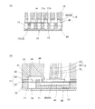
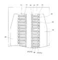
図1は、本発明の実施形態1に係るインクジェット式記録ヘッドの一例を示す断面図であり、図2はその要部を拡大した拡大断面図である。また図3は、流路形成基板の平面図である。
Hereinafter, the present invention will be described in detail based on embodiments.
(Embodiment 1)
FIG. 1 is a cross-sectional view showing an example of an ink jet recording head according to
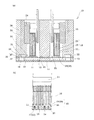
図示するように、本実施形態のインクジェット式記録ヘッド10は、複数の圧力発生室11が設けられた流路形成基板12と、各圧力発生室11に連通する複数のノズル13が穿設されたノズルプレート14と、流路形成基板12のノズルプレート14とは反対側の面に設けられる振動板15と、振動板15上の各圧力発生室11に対応する領域に設けられる圧力発生手段としての圧電素子16とを有する。
As shown in the figure, the ink
流路形成基板12には、各圧力発生室11が隔壁17によって区画されてその幅方向に複数並設されている。例えば、本実施形態では、複数の圧力発生室11が並設された列が流路形成基板12に2列設けられている。
In the flow
各圧力発生室11の列の外側には、各圧力発生室11にインクを供給するためのリザーバー18が、流路形成基板12を厚さ方向に貫通して設けられている。そして、各圧力発生室11とリザーバー18とは、インク供給路19を介して連通している。インク供給路19は、本実施形態では、圧力発生室11よりも狭い幅で形成されており、リザーバー18から圧力発生室11に流入するインクの流路抵抗を一定に保持する役割を果たしている。
A
また圧力発生室11は、本実施形態では、流路形成基板12を貫通することなく形成されており、圧力発生室11のリザーバー18とは反対の端部側には、流路形成基板12を貫通してノズル13に連通するノズル連通路20が形成されている。
Further, in this embodiment, the
このような流路形成基板12は、本実施形態では、シリコン単結晶基板からなり、流路形成基板12に設けられる圧力発生室11等は、流路形成基板12をエッチングすることによって形成されている。
In this embodiment, the flow
この流路形成基板12の一方面側にはノズルプレート14が接合されている。そして上述のように各ノズル13が流路形成基板12に設けられたノズル連通路20を介して各圧力発生室11と連通している。また、流路形成基板12の他方面側、すなわち圧力発生室11の開口面側には振動板15が接合され、各圧力発生室11はこの振動板15によって封止されている。そしてこの振動板15上には、圧力発生室11内にインク滴を噴射するための圧力を発生する圧力発生手段である圧電素子16が設けられている。圧電素子16は、その先端部が振動板15上に当接した状態で固定されている。
A
圧電素子16は、本実施形態では、圧電材料21と電極形成材料22及び23とを縦に交互にサンドイッチ状に挟んで積層され、振動に寄与しない不活性領域が固定基板24に固着されている。また、本実施形態では、圧電素子16の運動を阻害しない程度の空間を確保した状態でその空間を密封可能な圧電素子保持部25を有するヘッドケース26が振動板15上に固定されている。そして、圧電素子16が固定された固定基板24が、圧電素子16とは反対側の面でこのヘッドケース26に固定されている。
In the present embodiment, the
ここで、圧電素子16の先端が当接する振動板15は、例えば、樹脂フィルム等の弾性部材からなる弾性膜27と、この弾性膜27を支持する、例えば、金属材料等からなる支持板28との複合板で形成されており、弾性膜27側が流路形成基板12に接合されている。例えば、本実施形態では、弾性膜27は、厚さが数μm程度のPPS(ポリフェニレンサルファイド)フィルムからなり、支持板28は、厚さが数十μm程度のステンレス鋼板(SUS)からなる。また、振動板15の各圧力発生室11に対向する領域内には、圧電素子16の先端部が当接する島部29が設けられている。すなわち振動板15の各圧力発生室11の周縁部に対向する領域に他の領域よりも厚さの薄い薄肉部30が形成されて、この薄肉部30の内側にそれぞれ島部29が設けられている。
Here, the
また振動板15のリザーバー18に対向する領域には、薄肉部30と同様に、支持板28がエッチングにより除去されて実質的に弾性膜27のみで構成されるコンプライアンス部31が設けられている。なお、このコンプライアンス部31は、リザーバー18内の圧力変化が生じた時に、このコンプライアンス部31の弾性膜27が変形することによって圧力変化を吸収し、リザーバー18内の圧力を一定に維持する役割を果たす。
Further, in the region facing the
なおヘッドケース26のコンプライアンス部31に対向する部分には、コンプライアンス部31の変形を許容する空間である空間部32が形成されている。この空間部32はヘッドケース26に設けられる連通孔33を介して外部と連通している。つまり空間部32は大気開放されている。これによりコンプライアンス部31がリザーバー18の圧力変化に伴って良好に変形する。
A
このようなインクジェット式記録ヘッド10では、インク滴を噴射する際に、圧電素子16及び振動板15の変形によって各圧力発生室11の容積を変化させて所定のノズル13からインク滴を噴射させるようになっている。具体的には、図示しないインクカートリッジからリザーバー18にインクが供給されると、インク供給路19を介して各圧力発生室11にインクが分配される。実際には、圧電素子16に電圧を印加することにより圧電素子16を収縮させる。これにより、振動板15が圧電素子16と共に変形されて圧力発生室11の容積が広げられ、圧力発生室11内にインクが引き込まれる。そして、ノズル13に至るまで内部にインクを満たした後、図示しない駆動回路からの記録信号に従い、圧電素子16の電極形成材料22及び23に印加していた電圧を解除する。これにより、圧電素子16が伸張されて元の状態に戻ると共に振動板15も変位して元の状態に戻る。結果として圧力発生室11の容積が収縮して圧力発生室11内の圧力が高まりノズル13からインク滴が噴射される。
In such an ink
ここで、このように圧電素子16の駆動に伴う振動板15の変位により圧力発生室11内に圧力変化を生じさせてインク滴を噴射させようとすると、各圧力発生室11を区画している隔壁17も若干変形してしまう。このため、本発明では、以下に説明するように、隔壁17に間隙部40を設け、隔壁17の変形が隣接する圧力発生室11の圧力変動に影響を与えることがないようにしている。
Here, when the pressure change is caused in the
具体的には、図2及び図3に示すように、圧力発生室11間の各隔壁17には、少なくとも圧力発生室11に対応する部分に間隙部40が設けられている。本実施形態では、間隙部40は、圧力発生室11からインク供給路19に対応する部分に渡って連続的に設けられている。この間隙部40は、圧力発生室11の長手方向に沿って隔壁17を実質的に二つに分離して、第1の隔壁部17a及び第2の隔壁部17bを形成する空間(空気層)である。間隙部40が隔壁17に設けられていることで、圧電素子16を駆動して圧力発生室11内に圧力変動を生じさせた場合、各隔壁17の第1の隔壁部17a又は第2の隔壁部17bの何れか一方のみが変形する。すなわち、第1の隔壁部17aと第2の隔壁部17bとは、間隙部40によって分離されているため、一つの圧力発生室11の圧力変動によって第1及び第2の隔壁部17a,17bの両方が変形することはなない。
Specifically, as shown in FIGS. 2 and 3, each
したがって、複数のノズル13からインク滴を噴射させる際に、各圧力発生室11の圧力変動は、隣接する圧力発生室11の圧力変動の影響を受けることがなく、各ノズル13からインク滴を良好な噴射特性で噴射することができる。
Therefore, when ink droplets are ejected from the plurality of
なお、間隙部40は、第1及び第2の隔壁部17a,17bの変形を吸収できる程度に、隔壁17の少なくとも圧力発生室11に対応する領域に設けられていればよく、その幅等は適宜決定されればよい。例えば、本実施形態では、隔壁17(流路形成基板12)を厚さ方向に貫通することなく、圧力発生室11に対応する部分のみに間隙部40を形成するようにしたが、勿論、間隙部40は隔壁17を厚さ方向に貫通して設けられていてもよい。
The
また間隙部40に対向する領域の振動板15には、接続孔41が設けられている。この接続孔41は、本実施形態では振動板15を貫通して設けられ、ヘッドケース26の空間部32に連通している。上述したように、この空間部32は連通孔33を介して大気開放されている。これにより、第1及び第2の隔壁部17a,17bの変形を間隙部40によって確実に吸収することができる。
A
第1及び第2の隔壁部17a,17bが変形に伴って間隙部40の容積が変化するため、例えば、間隙部40が密封空間であると、第1及び第2の隔壁部17a,17bの変形に伴って間隙部40内の圧力が上昇し、第1及び第2の隔壁部17a,17bの変形を妨げる虞がある。すなわち各圧力発生室11の圧力変動が、隣接する圧力発生室11の圧力変動の影響を受けてしまう虞がある。
Since the volume of the
しかしながら、間隙部40が接続孔41を介して大気開放されていることで、第1及び第2の隔壁部17a,17bの変形を妨げることがない。つまり各圧力発生室11の圧力変動が、隣接する圧力発生室11の圧力変動の影響を受けることがない。したがって、各ノズル13からインク滴を良好に噴射することができる。
However, since the
また接続孔41は、ノズル13とは異なる方向の面、本実施形態ではノズル13が形成された面に相対向する面に設けられている。例えば、本実施形態では、流路形成基板12の一方面側に接合されたノズルプレート14にノズル13が形成されているのに対し、接続孔41は流路形成基板12の他方面側に接合された振動板15に形成されている。つまり接続孔41は、ノズル13が形成された面とは逆側の面に形成されている。さらに本発明では、接続孔41が、ノズル13と圧力発生室11との接続部(本実施形態では、ノズル連通路20)とは反対側の間隙部40の端部近傍に接続されている。
The
このように接続孔41が、ノズル13から離れた位置に設けられていることで、各ノズル13からインク滴をさらに良好に噴射させることができる。インク滴を噴射させる際に第1及び第2の隔壁部17a,17bが変形すると、間隙部40から接続孔41を介して外部に排出された空気によって周囲の気流に乱れが生じるが、上述のように接続孔41がノズル13から離れた位置に設けられていれば、この気流の乱れがノズル13から噴射されたインク滴に影響を及ぼすことがない。よって、各ノズル13からインク滴を良好に噴射させることができる。
As described above, since the
特に、本実施形態では、接続孔41が空間部32に連通するようにし、間隙部40が、接続孔41、空間部32及び連通孔33を介して外部に連通されるように構成されている。したがって、気流の乱れがインク滴に悪影響を及ぼすのをより確実に抑えることができる。さらに接続孔41を空間部32に連通させるようにすることで、比較的簡単な構造で、間隙部40を大気開放させることができる。
In particular, in the present embodiment, the
なお本実施形態では、このように接続孔41が空間部32に連通するようにしたが、勿論、接続孔41が直接外部に連通していてもよい。さらに接続孔41はノズル13とは異なる面に設けられていればよく、必ずしも振動板15に設けられている必要はない。
In the present embodiment, the
(他の実施形態)
以上、本発明の実施形態を説明したが、勿論、本発明は上述したものに限定されるものではない。例えば、インクジェット式記録ヘッドの構成は、上述したものに限定されるものではない。例えば、上述の実施形態では、圧力発生室11が流路形成基板12を厚さ方向に貫通することなく形成されノズル連通路20を介してノズル13と連通しているが、ノズル連通路20を設けずに圧力発生室11が流路形成基板12を厚さ方向に貫通して設けられていてもよい。この場合には、間隙部40も隔壁17を厚さ方向に貫通して設けられていることが好ましい。また、上述の実施形態では、圧力発生室11とノズル13とを連通するノズル連通路20を、流路形成基板12に形成するようにしたが、これに限定されず、ノズル連通路20は、圧力発生室11が形成される流路形成基板12とは別の基板に設けられていてもよい。
(Other embodiments)
As mentioned above, although embodiment of this invention was described, of course, this invention is not limited to what was mentioned above. For example, the configuration of the ink jet recording head is not limited to that described above. For example, in the above-described embodiment, the
また上述の実施形態では、圧力発生手段として、いわゆる縦振動型の圧電素子を例示して本発明を説明したが、圧力発生手段の構成は特に限定されず、例えば、いわゆる撓み振動型の圧電素子や、静電気力を用いるタイプのものや、発熱素子等であってもよい。 In the above-described embodiment, the present invention has been described by exemplifying a so-called longitudinal vibration type piezoelectric element as the pressure generating means. However, the configuration of the pressure generating means is not particularly limited, and for example, a so-called flexural vibration type piezoelectric element. Alternatively, a type using electrostatic force, a heating element, or the like may be used.
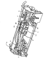
さらに、本実施形態のインクジェット式記録ヘッドは、インクカートリッジ等と連通するインク流路を具備する記録ヘッドユニットの一部を構成して、インクジェット式記録装置に搭載される。図4は、そのインクジェット式記録装置の一例を示す概略図である。 Furthermore, the ink jet recording head of this embodiment constitutes a part of a recording head unit including an ink flow path communicating with an ink cartridge and the like, and is mounted on the ink jet recording apparatus. FIG. 4 is a schematic view showing an example of the ink jet recording apparatus.
図4に示すように、インクジェット式記録装置における記録ヘッドユニット1A及び1Bは、インク供給手段を構成するカートリッジ2A及び2Bが着脱可能に設けられ、この記録ヘッドユニット1A及び1Bを搭載したキャリッジ3は、装置本体4に取り付けられたキャリッジ軸5に軸方向移動自在に設けられている。この記録ヘッドユニット1A及び1Bは、例えば、それぞれブラックインク組成物及びカラーインク組成物を吐出するものとしている。
As shown in FIG. 4, the
そして、駆動モーター6の駆動力が図示しない複数の歯車およびタイミングベルト7を介してキャリッジ3に伝達されることで、記録ヘッドユニット1A及び1Bを搭載したキャリッジ3はキャリッジ軸5に沿って移動される。一方、装置本体4にはキャリッジ軸5に沿ってプラテン8が設けられており、図示しない給紙ローラーなどにより給紙された紙等の記録媒体である記録シートSがプラテン8に巻き掛けられて搬送されるようになっている。
The driving force of the driving
なお上述した実施形態においては、本発明の液体噴射ヘッドの一例としてインクジェット式記録ヘッドを説明したが、液体噴射ヘッドの基本的構成は上述したものに限定されるものではない。本発明は、広く液体噴射ヘッドの全般を対象としたものであり、インク以外の液体を噴射するものにも勿論適用することができる。液体噴射ヘッドとしては、例えば、プリンター等の画像記録装置に用いられる各種の記録ヘッド、液晶ディスプレー等のカラーフィルターの製造に用いられる色材噴射ヘッド、有機ELディスプレー、FED(電界放出ディスプレー)等の電極形成に用いられる電極材料噴射ヘッド、バイオchip製造に用いられる生体有機物噴射ヘッド等が挙げられる。 In the above-described embodiment, the ink jet recording head has been described as an example of the liquid ejecting head of the present invention, but the basic configuration of the liquid ejecting head is not limited to the above. The present invention covers a wide range of liquid ejecting heads, and can naturally be applied to those ejecting liquids other than ink. Examples of the liquid ejecting head include various recording heads used in image recording apparatuses such as printers, color material ejecting heads used for manufacturing color filters such as liquid crystal displays, organic EL displays, and FED (field emission displays). Examples thereof include an electrode material ejection head used for electrode formation and a bioorganic matter ejection head used for biochip production.
11 圧力発生室、 12 流路形成基板、 13 ノズル、 14 ノズルプレート、 15 振動板、 16 圧電素子、 17 隔壁、 18 リザーバー、 19 インク供給路、 20 ノズル連通路、 21 圧電材料、 22,23 電極形成材料、 24 固定基板、 25 圧電素子保持部、 26 ヘッドケース、 27 弾性膜、 28 支持板、 29 島部、 30 薄肉部、 31 コンプライアンス部、 32 空間部、 33 連通孔、 40 間隙部、 41 接続孔
DESCRIPTION OF
Claims (4)
前記隔壁には少なくとも前記圧力発生室に対応する領域に間隙部が設けられており、該間隙部は前記ノズルとは異なる方向の面に設けられ且つ前記圧力発生室と前記ノズルとの接続部とは反対側の端部近傍で接続される接続孔を介して外部と連通されていることを特徴とする液体噴射ヘッド。 A nozzle for ejecting liquid droplets, a plurality of pressure generating chambers connected to the nozzle and partitioned by a partition, and pressure generating means for generating pressure for droplet ejection in the pressure generating chamber,
The partition wall is provided with a gap at least in a region corresponding to the pressure generation chamber, the gap is provided on a surface in a direction different from the nozzle, and a connection portion between the pressure generation chamber and the nozzle. Is connected to the outside through a connection hole connected in the vicinity of the opposite end.
Priority Applications (1)
| Application Number | Priority Date | Filing Date | Title |
|---|---|---|---|
| JP2008324023A JP2010143130A (en) | 2008-12-19 | 2008-12-19 | Liquid jet head and liquid jetting apparatus |
Applications Claiming Priority (1)
| Application Number | Priority Date | Filing Date | Title |
|---|---|---|---|
| JP2008324023A JP2010143130A (en) | 2008-12-19 | 2008-12-19 | Liquid jet head and liquid jetting apparatus |
Publications (1)
| Publication Number | Publication Date |
|---|---|
| JP2010143130A true JP2010143130A (en) | 2010-07-01 |
Family
ID=42564048
Family Applications (1)
| Application Number | Title | Priority Date | Filing Date |
|---|---|---|---|
| JP2008324023A Pending JP2010143130A (en) | 2008-12-19 | 2008-12-19 | Liquid jet head and liquid jetting apparatus |
Country Status (1)
| Country | Link |
|---|---|
| JP (1) | JP2010143130A (en) |
Cited By (2)
| Publication number | Priority date | Publication date | Assignee | Title |
|---|---|---|---|---|
| JP2019116088A (en) * | 2017-12-27 | 2019-07-18 | セイコーエプソン株式会社 | Liquid discharge head and flow path structure |
| JP2020044779A (en) * | 2018-09-20 | 2020-03-26 | 株式会社リコー | Liquid discharge head, liquid discharge unit, device for discharging liquid |
-
2008
- 2008-12-19 JP JP2008324023A patent/JP2010143130A/en active Pending
Cited By (3)
| Publication number | Priority date | Publication date | Assignee | Title |
|---|---|---|---|---|
| JP2019116088A (en) * | 2017-12-27 | 2019-07-18 | セイコーエプソン株式会社 | Liquid discharge head and flow path structure |
| JP2020044779A (en) * | 2018-09-20 | 2020-03-26 | 株式会社リコー | Liquid discharge head, liquid discharge unit, device for discharging liquid |
| JP7095522B2 (en) | 2018-09-20 | 2022-07-05 | 株式会社リコー | Liquid discharge head, liquid discharge unit, liquid discharge device |
Similar Documents
| Publication | Publication Date | Title |
|---|---|---|
| JP5776880B2 (en) | Liquid ejecting head and liquid ejecting apparatus | |
| US8794736B2 (en) | Liquid ejecting head and liquid ejecting apparatus | |
| JP2008284725A (en) | Liquid ejecting head and liquid ejecting apparatus | |
| JP2012020422A (en) | Liquid ejecting head, liquid ejecting head unit and liquid ejecting apparatus | |
| JP2009178951A (en) | Liquid ejecting head and liquid ejecting apparatus | |
| JP2011189523A (en) | Liquid ejecting head and liquid ejecting apparatus | |
| JP4911306B2 (en) | Liquid ejecting head and liquid ejecting apparatus | |
| JP5370648B2 (en) | Liquid ejecting head and liquid ejecting apparatus | |
| JP5024543B2 (en) | Liquid ejecting head and liquid ejecting apparatus | |
| JP5218730B2 (en) | Liquid ejecting head and liquid ejecting apparatus | |
| JP2010143130A (en) | Liquid jet head and liquid jetting apparatus | |
| JP6123998B2 (en) | Liquid ejecting head and liquid ejecting apparatus | |
| JP2012218195A (en) | Liquid ejection head, and liquid ejection device | |
| JP2008221825A (en) | Liquid ejecting head and liquid ejecting apparatus | |
| JP4935994B2 (en) | Liquid ejecting head unit and liquid ejecting apparatus | |
| JP2014113787A (en) | Liquid jet head and liquid jet device | |
| JP4605356B2 (en) | Liquid ejecting head unit and liquid ejecting apparatus | |
| JP2011093254A (en) | Head and device for ejecting liquid | |
| JP5950083B2 (en) | Liquid ejecting head and liquid ejecting apparatus | |
| JP5645005B2 (en) | Liquid ejecting head and liquid ejecting apparatus | |
| JP2009226929A (en) | Method of driving liquid jet head and liquid jet apparatus | |
| JP2008023799A (en) | Liquid ejecting head and liquid ejecting apparatus | |
| JP2007216474A (en) | Liquid ejecting head and liquid ejecting apparatus | |
| JP2013248843A (en) | Liquid injection head and liquid injection device | |
| JP2006248166A (en) | Liquid ejecting head and liquid ejecting apparatus |