JP2010142828A - Tool for welding reinforcing bar - Google Patents
Tool for welding reinforcing bar Download PDFInfo
- Publication number
- JP2010142828A JP2010142828A JP2008321011A JP2008321011A JP2010142828A JP 2010142828 A JP2010142828 A JP 2010142828A JP 2008321011 A JP2008321011 A JP 2008321011A JP 2008321011 A JP2008321011 A JP 2008321011A JP 2010142828 A JP2010142828 A JP 2010142828A
- Authority
- JP
- Japan
- Prior art keywords
- reinforcing bar
- welding
- cover body
- cover
- gas
- Prior art date
- Legal status (The legal status is an assumption and is not a legal conclusion. Google has not performed a legal analysis and makes no representation as to the accuracy of the status listed.)
- Granted
Links
- 238000003466 welding Methods 0.000 title claims abstract description 74
- 230000003014 reinforcing effect Effects 0.000 title claims abstract description 70
- 239000002184 metal Substances 0.000 claims abstract description 45
- 229910052751 metal Inorganic materials 0.000 claims abstract description 45
- 238000004891 communication Methods 0.000 claims description 23
- 238000000034 method Methods 0.000 claims description 8
- 238000010276 construction Methods 0.000 claims description 6
- 239000007789 gas Substances 0.000 abstract description 53
- 238000004140 cleaning Methods 0.000 abstract description 8
- QVGXLLKOCUKJST-UHFFFAOYSA-N atomic oxygen Chemical compound [O] QVGXLLKOCUKJST-UHFFFAOYSA-N 0.000 abstract description 3
- 229910052760 oxygen Inorganic materials 0.000 abstract description 3
- 239000001301 oxygen Substances 0.000 abstract description 3
- 239000000203 mixture Substances 0.000 abstract 1
- XEEYBQQBJWHFJM-UHFFFAOYSA-N Iron Chemical compound [Fe] XEEYBQQBJWHFJM-UHFFFAOYSA-N 0.000 description 14
- 230000017525 heat dissipation Effects 0.000 description 13
- CURLTUGMZLYLDI-UHFFFAOYSA-N Carbon dioxide Chemical compound O=C=O CURLTUGMZLYLDI-UHFFFAOYSA-N 0.000 description 8
- 229910052742 iron Inorganic materials 0.000 description 7
- 238000010586 diagram Methods 0.000 description 5
- 238000012423 maintenance Methods 0.000 description 5
- 230000005855 radiation Effects 0.000 description 5
- 229910000831 Steel Inorganic materials 0.000 description 4
- 229910002092 carbon dioxide Inorganic materials 0.000 description 4
- 239000001569 carbon dioxide Substances 0.000 description 4
- 239000010959 steel Substances 0.000 description 4
- 238000005272 metallurgy Methods 0.000 description 3
- 238000004544 sputter deposition Methods 0.000 description 3
- 239000000919 ceramic Substances 0.000 description 2
- 238000011109 contamination Methods 0.000 description 2
- 230000003111 delayed effect Effects 0.000 description 2
- 238000012986 modification Methods 0.000 description 2
- 230000004048 modification Effects 0.000 description 2
- 238000007747 plating Methods 0.000 description 2
- 230000003670 easy-to-clean Effects 0.000 description 1
- 230000000694 effects Effects 0.000 description 1
- 210000002445 nipple Anatomy 0.000 description 1
- 230000002265 prevention Effects 0.000 description 1
- 230000009466 transformation Effects 0.000 description 1
Images

Landscapes
- Butt Welding And Welding Of Specific Article (AREA)
Abstract
Description
本発明は、鉄筋を相互にエンクローズド溶接工法によって溶接接続する際にシールドする治具に関し、特に鉄筋溶接用の裏当て金の補修・清掃し易くし溶接品質を保持できる鉄筋溶接用治具に関する。 The present invention relates to a jig for shielding rebars when they are welded and connected to each other by an enclosed welding method, and more particularly to a rebar welding jig that can easily repair and clean a backing metal for rebar welding and maintain welding quality. .
建築現場等において鉄筋を接続する方法の一つには、鉄筋径とほぼ同じ径の継手パイプまたは半円に折り曲げた鋼板に、鉄筋同士を突き合わせた溶接部を挿入し、その継手パイプの側面開口部または鋼板の開口部から溶接棒を挿入して、鉄筋同士を溶着するようにしたものがある。このように継手パイプや半円に折り曲げた鋼板を用いた場合、ガスシールドの面で不十分で清掃もしにくい問題があった。 One method of connecting reinforcing bars at a construction site is to insert a welded part where the reinforcing bars are butted into a joint pipe with a diameter almost the same as the diameter of the reinforcing bar or a steel plate folded into a semicircle, and open the side of the joint pipe. There is one in which a welding rod is inserted from an opening of a steel plate or a steel plate to weld the reinforcing bars together. Thus, when using a joint pipe or a steel plate bent into a semicircle, there was a problem that the gas shield surface was insufficient and cleaning was difficult.
鉄筋を接続する方法の他の一つには、溶接箇所をカバーで覆いシールドガスを充満させて酸素の混入を確実に防止した中で溶接を行う、いわゆるエンクローズド法と呼ばれる方法が知られている。炭酸ガスシールド工法が知られ令ル。 Another method for connecting reinforcing bars is known as the so-called enclosed method, in which welding is performed while covering the welded portion with a cover and filling the shield gas to reliably prevent oxygen contamination. Yes. The carbon dioxide shield construction method is known.
このエンクローズド法においては、突き合わせた鉄筋にその側方両側からカバーで挟むように取付けて、カバーに設けられた窓から溶接棒を挿入して溶接を行うものである。 In this enclosing method, welding is carried out by inserting a welding rod from a window provided in the cover, and attaching it to the abutted reinforcing bars so as to be sandwiched by covers from both sides.
具体的に述べると、カバーの一方に(「第一の治具」という)には、シールドガスのホースと溶接部に臨ませた窓と、両側方に鉄筋を挟むための半円の切り欠きが設けて有り、更にガスを内部に噴出させための噴出口と、窓に沿ってエアスクリーンを形成する吹き出し口が形成されている。また、他方のカバー(「第二の治具」という)には、第一の治具の切り欠きと同一の位置に半円の切り欠きがあり、さらに内面にはこの切り欠きと同一形状の半円筒状の裏当て金が前記第一の治具の窓に正対して形成してある。そして、鉄筋にこれら第一の治具と第二の治具をネジ等の止め金具で固定し上述のように窓から溶接棒を挿入して溶接する(例えば特開平1−202367号公報:特許文献1参照)。 Specifically, one side of the cover (referred to as the “first jig”) has a shield gas hose, a window facing the weld, and a semi-circular notch for sandwiching reinforcing bars on both sides. Further, there are formed an outlet for ejecting gas into the interior and an outlet for forming an air screen along the window. The other cover (referred to as “second jig”) has a semicircular cutout at the same position as the cutout of the first jig, and the inner surface has the same shape as this cutout. A semicylindrical backing metal is formed facing the window of the first jig. Then, the first jig and the second jig are fixed to the reinforcing bar with a fastener such as a screw, and the welding rod is inserted from the window as described above and welded (for example, Japanese Patent Laid-Open No. 1-202367: Patent Reference 1).
また、裏当て金にセラミックを用いたものもある(特公平7−39040号公報:特許文献2参照)。 In addition, there is also a ceramic using a backing metal (see Japanese Patent Publication No. 7-39040: Patent Document 2).
第一の治具の溶接口とガス吹き出し口が丸パイプと一体化になっているものがある。 In some cases, the welding port and the gas outlet of the first jig are integrated with the round pipe.
また、第二の治具では、鉄やセラミック等からなる放熱当て金をカバー本体とは分割し、放熱当て金に直接溶接したり、鉄の裏当て金を設けてその裏当て金に直接溶接したりしていたが、放熱当て金自体は一体化していた。また、溶接時にスパッタ等に熱や火花によって放熱当て金が短期間で損傷を受けてしまい、良好な溶接に困難が生じたり、放熱当て金を頻繁に交換しなければならなかった。 Also, in the second jig, the heat dissipation pad made of iron or ceramic is divided from the cover body and welded directly to the heat dissipation pad, or an iron backing metal is provided and welded directly to the backing metal. However, the heat sink was integrated. In addition, the heat-dissipating metallurgy was damaged in a short period of time by welding due to heat or sparks on the spatter and the like, making it difficult to perform good welding, and the heat-radiating metallurgy had to be frequently replaced.
また、鉄筋の太さが異なるものになると、その度に、放熱当て金および裏当て金の寸法の異なる鉄筋溶接用治具を用意しなければならず、治具のコストや管理に負担が大きかった。
本発明は、上述の実情に鑑み、酸素混入の防止および清掃のしやすさを実現しつつ、鉄筋の寸法が異なっても放熱当て金等の部品の交換を要せずに対応することができる鉄筋溶接用治具を提供しようとするものである。 In view of the above situation, the present invention can cope with prevention of oxygen contamination and ease of cleaning, and even if the size of the reinforcing bar is different, it is not necessary to replace parts such as a heat dissipation pad. It intends to provide a jig for rebar welding.
本発明は、第一のカバーとこの第一のカバーに着脱自在な第二のカバーを鉄筋の両側より組付け、施工場所における溶接の際に鉄筋の溶接部を覆い、溶接部周囲にシールドガスを導入するようにしたエンクローズド溶接法に用いる鉄筋溶接用治具において、
前記第一のカバーと第二のカバーの鉄筋の長さ方向に対応する軸方向側の面部には鉄筋に組付けた際に該鉄筋を挿通させる半円の切り欠きを設け、
且つ前記第一のカバーには、溶接部に臨ませて溶接棒を挿入し運棒しうる窓と、シールドガスの導入ホースが接続される導入口と、当該導入口に連通し前記窓の開口面に平行な方向に開く当該窓縁部に設けられた第1のガス噴出口と、前記導入口に連通し内部に向けてガスを噴出させる第2のガス噴出口とを設け、
第二のカバー内部には、前記鉄筋の溶接部に対応する位置の第1の部分と溶接部以外の位置に対応する第2の部分に前記軸方向に複数の部分に分割された放熱当て金と、前記放熱当て金の第1の部分の内側部であって溶接部に対面する箇所に配設された鉄製の裏当て金とを設けたことを特徴とする鉄筋溶接用治具である。
In the present invention, a first cover and a second cover that can be attached to and detached from the first cover are assembled from both sides of the reinforcing bar, the welding part of the reinforcing bar is covered during welding at a construction site, and a shielding gas is surrounded around the welding part In the reinforcing bar welding jig used for the closed welding method that introduces
A semicircular cutout for inserting the reinforcing bar is provided on the axial side surface portion corresponding to the length direction of the reinforcing bar of the first cover and the second cover,
In addition, the first cover has a window through which a welding rod can be inserted and transported facing the welded portion, an introduction port to which a shield gas introduction hose is connected, an opening of the window communicating with the introduction port A first gas jet port provided at the window edge that opens in a direction parallel to the surface, and a second gas jet port that communicates with the introduction port and jets gas toward the inside;
Inside the second cover, there is a heat dissipating brace divided into a plurality of portions in the axial direction into a first portion at a position corresponding to the welded portion of the reinforcing bar and a second portion corresponding to a position other than the welded portion. And a rebar welding jig provided with an iron backing metal disposed in a portion facing the welded portion inside the first portion of the heat dissipation metallurgy.
本発明においては、第一のカバーは、外側カバー体内に内側カバー体が密接して設けられ、内側カバー体の外側カバー体に密接する面部には、該外側カバー体の導入口内側から前記第1のガス噴出口および第2のガス噴出口に繋がる連通用溝を形成し、外側カバー体内に内側カバー体を密接することにより、連通用溝と外側カバー体との内面でガス連通路を形成したことが好適である。 In the present invention, the first cover is provided with the inner cover member in close contact with the outer cover member, and the surface portion of the inner cover member that is in close contact with the outer cover member is provided with the first cover from the inside of the introduction port of the outer cover member. A communication groove connected to the first gas outlet and the second gas outlet is formed, and the inner cover body is brought into close contact with the outer cover body, thereby forming a gas communication path between the inner surface of the communication groove and the outer cover body. It is preferred that
また、本発明においては、内側カバー体は第2のガス噴出口を含む分割線によって複数の部分に分割されており、第2のガス噴出口は各部分の分割面に溝部を形成することで構成したことが好適である。 Moreover, in this invention, the inner side cover body is divided | segmented into the several part by the dividing line containing the 2nd gas ejection port, and the 2nd gas ejection port forms a groove part in the division surface of each part. It is preferable to configure.
また、本発明においては、外径の異なる鉄筋端部同士を対向させて溶接する鉄筋溶接用治具であって、裏当て金に各鉄筋の外径に等しい内径の各部分を形成したことが好適である。 Further, in the present invention, it is a reinforcing bar welding jig for welding the reinforcing bar ends with different outer diameters facing each other, and each portion having an inner diameter equal to the outer diameter of each reinforcing bar is formed on the backing metal. Is preferred.
本発明の鉄筋溶接用治具によれば、第二のカバー内部には、前記鉄筋の溶接部に対応する位置の第1の部分と溶接部以外の位置に対応する第2の部分に前記軸方向に複数の部分に分割された放熱当て金と、前記放熱当て金の第1の部分の内側部であって溶接部に対面する箇所に配設された鉄製の裏当て金とを設けたので、溶接部の溶接した際に裏当て金を溶接しても、次回の溶接時に裏当て金を交換すれば容易に溶接作業ができる。 According to the reinforcing bar welding jig of the present invention, the second cover has the first portion at a position corresponding to the welded portion of the reinforcing bar and the second portion corresponding to a position other than the welded portion. Because the heat dissipating brace divided into a plurality of parts in the direction and the iron backing metal disposed at the location facing the welded part inside the first part of the heat dissipating brace Even if the backing metal is welded when the welded portion is welded, the welding work can be easily performed by replacing the backing metal at the next welding.
また、放熱当て金がスパッタなどで破損しても第1の部分または第2の部分を適宜に交換すれば良いため溶接作業が滞ることがない。 Further, even if the heat dissipation metal is damaged by sputtering or the like, the welding operation is not delayed because the first portion or the second portion may be replaced as appropriate.
また、施工場所に鉄筋の径が異なるものに使用する場合に、裏当て金および必要に応じて放熱当て金を交換すれば1台の鉄筋溶接用治具で適切かつ簡単に対応して溶接できるため、種々の鉄筋の径に応じて当該溶接用治具を用意する必要が無いので治具のコストや管理に負担が掛らない。 In addition, when using a rebar with different diameters at the construction site, if the backing metal and the heat dissipation metal are replaced as required, welding can be performed appropriately and easily with a single reinforcing bar welding jig. For this reason, it is not necessary to prepare the welding jig according to the diameters of various reinforcing bars, so that there is no burden on the cost and management of the jig.
また、第二のカバー内の放熱当て金の第1の部分と第2の部分、および裏当て金からなす各部にばらして取りやすいので第二のカバー内を清掃しやすい。 Moreover, since it is easy to disperse | distribute to each part made from the 1st part and 2nd part of a heat dissipation brace in a 2nd cover, and a backing metal, the inside of a 2nd cover is easy to clean.
なお、本発明において、第一のカバーは、外側カバー体内に内側カバー体が密接して設けられ、内側カバー体の外側カバー体に密接する面部には、該外側カバー体の導入口内側から前記第1のガス噴出口および第2のガス噴出口に繋がる連通用溝を形成し、外側カバー体内に内側カバー体を密接することにより、連通用溝と外側カバー体との内面でガス連通路を形成すれば、外側カバー体内面を平坦にして内側カバー体内に連通用溝を形成するだけで容易にガス連通路を形成することができる。また、ガス連通路の複雑な曲がりのあるものでも容易に形成できる。また、外側カバー体から内側カバー体を取り去ればそれぞれの清掃やメンテナンスが容易にできる。 In the present invention, the first cover is provided with the inner cover body in intimate contact with the outer cover body, and the surface portion of the inner cover body in close contact with the outer cover body is formed from the inside of the inlet of the outer cover body. A communication groove connected to the first gas outlet and the second gas outlet is formed, and the inner cover body is brought into close contact with the outer cover body, whereby the gas communication path is formed on the inner surfaces of the communication groove and the outer cover body. If formed, it is possible to easily form the gas communication path simply by flattening the inner surface of the outer cover body and forming the communication groove in the inner cover body. Further, even a gas communication passage having a complicated curve can be easily formed. Further, if the inner cover body is removed from the outer cover body, cleaning and maintenance of each can be facilitated.
また、本発明において、内側カバー体は第2のガス噴出口を含んで分割されており、第2のガス噴出口は分割面に溝部を形成することで構成すれば、第2のガス噴出口の形成を容易にでき、複雑なガス噴出口の形成も容易である。また、外側カバー体から内側カバー体を取り去ればそれぞれの清掃やメンテナンスが容易にできる。 Further, in the present invention, the inner cover body is divided so as to include the second gas outlet, and if the second gas outlet is formed by forming a groove on the dividing surface, the second gas outlet is provided. Can be easily formed, and a complicated gas ejection port can be easily formed. Further, if the inner cover body is removed from the outer cover body, cleaning and maintenance of each can be facilitated.
また、本発明において、内側カバー体は第2のガス噴出口を含む分割線によって複数の部分に分割されており、第2のガス噴出口は各部分の分割面に溝部を形成することで構成すれば、第2のガス噴出口の形成を容易にでき、複雑なガス噴出口の形成も容易である。また、外側カバー体から内側カバー体を取り去ればそれぞれの清掃やメンテナンスが容易にできる。 Further, in the present invention, the inner cover body is divided into a plurality of parts by a dividing line including the second gas outlet, and the second gas outlet is configured by forming a groove on the dividing surface of each part. By doing so, it is possible to easily form the second gas ejection port, and it is also easy to form a complicated gas ejection port. Further, if the inner cover body is removed from the outer cover body, cleaning and maintenance of each can be facilitated.
また、本発明において、外径の異なる鉄筋端部同士を対向させて溶接する鉄筋溶接用治具であって、裏当て金に各鉄筋の外径に等しい内径の各部分を形成すれば、外径の異なる鉄筋端部同士を容易に対応して溶接できるという優れた効果を奏し得る。 Further, in the present invention, a reinforcing bar welding jig for welding the reinforcing bar ends having different outer diameters to face each other, and forming each part of the inner diameter equal to the outer diameter of each reinforcing bar on the backing metal, It is possible to achieve an excellent effect that the ends of the reinforcing bars having different diameters can be easily matched and welded.
以下、本発明の実施形態について、添付図面を参照して説明する。 Embodiments of the present invention will be described below with reference to the accompanying drawings.
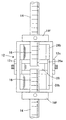
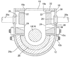
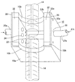
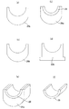
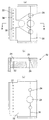
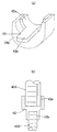
図1〜図7は本発明の実施形態に係る鉄筋溶接用治具の一例であって、図中、同一の符号を付した部分は同一物を表わす。図1は実施形態に係る鉄筋溶接用治具の取付け前の状態の説明図、図2は第一のカバーを取り外した第二のカバー内を見た正面図、図3は鉄筋の端部同士を突き合わせた溶接部を中心に横断視した鉄器溶接用治具の説明図、図4は第一のカバーの取付け側から見た説明図、図5(a)は第1の放熱当て金、(b)は裏当て金と第2の放熱当て金の重なった状態図、(c)は第2の放熱当て金、(d)は金属製放熱板、(e)は(b)の斜視図、(f)は裏当て金の斜視図、図6は第一のカバーにおける内側カバー体の説明図(a)は外側カバー体に接する側の外面図、(b)は(a)のB−B線断面図、(c)は溶接空間に面する側の図、図7(a)、(b)は裏当て金の変形例の斜視図、平面図である。 1 to 7 are examples of a reinforcing bar welding jig according to an embodiment of the present invention. In the drawings, the same reference numerals denote the same parts. FIG. 1 is an explanatory diagram of a state before mounting a reinforcing bar welding jig according to the embodiment, FIG. 2 is a front view of the inside of the second cover with the first cover removed, and FIG. FIG. 4 is an explanatory diagram viewed from the side of the first cover attached, FIG. 5 (a) is a first heat radiation pad, b) is a state diagram in which the backing metal and the second heat radiation metal pad are overlapped, (c) is the second heat radiation metal pad, (d) is a metal heat radiation plate, (e) is a perspective view of (b), (F) is a perspective view of the backing metal, FIG. 6 is an explanatory view of the inner cover body in the first cover, (a) is an external view of the side in contact with the outer cover body, and (b) is BB of (a). Sectional drawing of a line, (c) is a figure of the side facing welding space, FIG.
図1〜図3に示すように、実施形態に係る鉄筋用溶接治具は、第一のカバー10とこの第一のカバー10に着脱自在な第二のカバー12によって、突き合わせた鉄筋14(の溶接部16)の両側より挟み付けるように組付けて、施工場所における溶接の際に鉄筋14の溶接部16を覆い、溶接部16周囲に炭酸ガス等のシールドガスを導入するようにしたエンクローズド溶接法に用いる鉄筋溶接用治具に係るものである。
As shown in FIGS. 1 to 3, the reinforcing bar welding jig according to the embodiment includes a
前記第一のカバー10と第二のカバー12の鉄筋14の長さ方向に対応する軸方向側の各面部10a、12aには鉄筋14に組付けた際に該鉄筋14を挿通させる半円の切り欠き10b、12bを設けている。なお、第一のカバー10と第二のカバー12によって鉄筋14を両側より挟み付けたら、第一のカバー10と第二のカバー12同士をそれらの側面部に設けた係止具10c、12cで締め付け固定する。また、溶接に先立ち、鉄筋14端部同士を図示しないバイス等の固定具14fで固定しておく。前記第一のカバー10と第二のカバー12との係止具10c、12cをこの固定具と兼用することもできる。
A semicircular shape through which the reinforcing
前記第一のカバー10には、溶接部16に臨ませて溶接棒を挿入し運棒(溶接棒を接近させて溶接させていく際に自由に溶接棒先端を移動するように)しうる窓18と、シールドガスの導入ホース20aが接続される導入口20と、当該導入口20に連通し前記窓18の開口面に平行な方向に開く当該窓縁部18aに設けられた第1のガス噴出口22と、前記導入口20に連通し内部に向けてガスを噴出させる第2のガス噴出口24とを設けている。なお、導入ホース20aには、図示しない炭酸ガスボンベから炭酸ガスが供給されるようになっている。又、導入口20はホースを気密に装着できるニップルが設けられている。
The
第二のカバー12は概略半円筒形状の箱状に形成されており、その内部には、前記鉄筋14の溶接部16に対応する位置の第1の部分26aと溶接部16以外の位置に対応する第2の部分26bに前記軸方向に3つ(複数の例で、2つまた4以上でもよい)の部分に分割された鉄製の放熱当て金26と、前記放熱当て金26の第1の部分26aの内側部であって溶接部16に対面する箇所に配設された鉄製の裏当て金28とを設けたものである(図2参照)。放熱当て金26と裏当て金28との詳細を図5に示す。放熱当て金26(第1の部分26a、第2の部分26b)のいずれも、鉄筋14に対向する箇所が鉄筋14の外形に対応して凹部に形成されており(図5で上方部分)、裏当て金28は、放熱当て金26の第1の部分26aの上方の凹部に沿った弧状に形成されている。
The
詳細には、第一のカバー10は、外側カバー体30内の軸方向に対して垂直方向の両側部には、内側カバー体32が密接してネジ止め等によって設けられ、内側カバー体32の外側カバー体30に密接する面部32aには、該外側カバー体30の導入口20内側から前記第1のガス噴出口22および第2のガス噴出口24に繋がる連通用溝34を形成し、外側カバー体30内に内側カバー体32を密接することにより、連通用溝34と外側カバー体30との内面でガス連通路36を形成したものである(図3参照)。
Specifically, the
また、内側カバー体32は第2のガス噴出口24を含む分割線38によって複数の部分に分割されており、第2のガス噴出口24は各部分の分割面に溝部を形成することで構成したものである(図6参照)。また、第一のカバー10内の軸方向の上下面部には図4、図5(d)に示す、金属製放熱板32bが配設され溶接時のスパッタで加熱するのを放熱するようにしている。
Further, the
本実施形態の鉄筋溶接用治具によれば、第二のカバー12内部には、前記鉄筋14の溶接部16に対応する位置の第1の部分26aと溶接部16以外の位置に対応する第2の部分26b(実施形態では上下2つ)に前記軸方向に複数の部分に分割された放熱当て金26と、前記放熱当て金26の第1の部分26aの内側部であって溶接部16に対面する箇所に配設された鉄製の裏当て金28とを設けたので、溶接部16の溶接した際に裏当て金28を鉄筋14に溶接しまたは消耗させても、次回の溶接時に裏当て金28を補充・交換すれば容易に溶接作業ができる。
裏当て金28は厚さを0mm〜厚物まで適宜に寸法のものを用いることができる。また、幅を小から大まで適宜の寸法のものを採用することができる。
According to the reinforcing bar welding jig of the present embodiment, the
The backing
また、放熱当て金26がスパッタなどで破損しても必要に応じて、第1の部分26a、第2の部分26bを適宜に交換すれば良いため溶接作業が滞ることがない。
Further, even if the heat dissipating pad 26 is damaged by sputtering or the like, the welding operation is not delayed because the
また、上記構成の鉄筋溶接用治具を鉄筋14の径が異なるものに使用する場合に、裏当て金28と必要に応じて放熱当て金26の第1の部分26a、第2の部分26bを交換すれば適切に簡単に対応できるため、種々の径の鉄筋14に応じて溶接用治具を用意する必要が無いので治具のコストや管理に負担が掛らない。
Further, when the reinforcing bar welding jig having the above-described configuration is used for one having a different diameter of the reinforcing
また、第二のカバー12内の放熱当て金26の第1の部分26aと第2の部分26b、および裏当て金28からなす各部にばらして取りやすいので第二のカバー12内を清掃しやすい。
Further, since the
なお、第一のカバー10は、外側カバー体30内に内側カバー体32が密接して設けられ、内側カバー体32の外側カバー体30に密接する面部には、該外側カバー体30の導入口20内側から前記第1のガス噴出口22および第2のガス噴出口24に繋がる連通用溝34を形成し、外側カバー体30内に内側カバー体32を密接することにより、連通用溝34と外側カバー体30との内面でガス連通路36を形成すれば、外側カバー体30内面を平坦にして内側カバー体32内に連通用溝34を形成するだけで容易にガス連通路36を形成することができる。また、ガス連通路36の複雑な曲がりのあるものでも容易に形成できる。また、外側カバー体30から内側カバー体32を取り去ればそれぞれの清掃やメンテナンスが容易にできる。
In the
また、内側カバー体32は第2のガス噴出口24を含んで分割されており、第2のガス噴出口24は分割面に溝部(連通用溝34)を形成することで構成すれば、第2のガス噴出口24の形成を容易にでき、複雑なガス噴出口の形成も容易である。また、外側カバー体30から内側カバー体32を取り去ればそれぞれの清掃やメンテナンスが容易にできる。
Further, the
なお、本発明は、上記の実施形態に限定されず、種々に変形実施できる。 In addition, this invention is not limited to said embodiment, Various deformation | transformation implementation is possible.
例えば、図7に示すように、外径の異なる鉄筋40A、40B端部同士を対向させて溶接する鉄筋溶接用治具とする場合、裏当て金42に各鉄筋40A,40Bの外径にそれぞれ等しい内径の各部分42a、42bを形成したものにできる。
For example, as shown in FIG. 7, when using a reinforcing bar welding jig for welding the reinforcing
このように外径の異なる鉄筋40A、40B端部同士を対向させて溶接する鉄筋溶接用治具であって裏当て金42に各鉄筋の外径に等しい内径の各部分42a、42b(大部分、小部分)を形成すれば、外径の異なる鉄筋端部同士を容易に対応して溶接できる。
Reinforcing bar welding jigs for welding the reinforcing
10 第一のカバー
10a 第一のカバーの上下面部
10b 第一のカバーの切り欠き
10c 第一のカバーの係止具
12 第二のカバー
12a 第二のカバーの上下面部
12b 第二のカバーの切り欠き
12c 第二のカバーの係止具
14 鉄筋
14f 固定具
16 溶接部
18 窓
18a 窓縁部
20 導入口
20a 導入ホース
22 ガス噴出口
24 ガス噴出口
26 放熱当て金
26a 第1の部分
26b 第2の部分
28 裏当て金
30 外側カバー体
30a 外側カバー体の内側の密接する面部
32 内側カバー体
32a 内側カバー体の外側の密接する面部
32b 上下の金属製放熱板
34 連通用溝
36 ガス連通路
38 分割線
40A,40B 異径の各鉄筋
42 変形例に係る裏当て金
42a 裏当て金の寸法の異なる各部分
DESCRIPTION OF
Claims (4)
前記第一のカバーと第二のカバーの鉄筋の長さ方向に対応する軸方向側の面部には鉄筋に組付けた際に該鉄筋を挿通させる半円の切り欠きを設け、
且つ前記第一のカバーには、溶接部に臨ませて溶接棒を挿入し運棒しうる窓と、シールドガスの導入ホースが接続される導入口と、当該導入口に連通し前記窓の開口面に平行な方向に開く当該窓縁部に設けられた第1のガス噴出口と、前記導入口に連通し内部に向けてガスを噴出させる第2のガス噴出口とを設け、
第二のカバー内部には、前記鉄筋の溶接部に対応する位置の第1の部分と溶接部以外の位置に対応する第2の部分に前記軸方向に複数の部分に分割された放熱当て金と、前記放熱当て金の第1の部分の内側部であって溶接部に対面する箇所に配設された鉄製の裏当て金とを設けたことを特徴とする鉄筋溶接用治具。 The first cover and the second cover that can be attached to and detached from the first cover are assembled from both sides of the reinforcing bar so that the welded part of the reinforcing bar is covered during welding at the construction site, and shielding gas is introduced around the welded part. In the reinforcing bar welding jig used for the enclosed welding method,
A semicircular cutout for inserting the reinforcing bar is provided on the axial side surface portion corresponding to the length direction of the reinforcing bar of the first cover and the second cover,
In addition, the first cover has a window through which a welding rod can be inserted and transported facing the welded portion, an introduction port to which a shield gas introduction hose is connected, an opening of the window communicating with the introduction port A first gas jet port provided at the window edge that opens in a direction parallel to the surface, and a second gas jet port that communicates with the introduction port and jets gas toward the inside;
Inside the second cover, there is a heat dissipating brace divided into a plurality of portions in the axial direction into a first portion at a position corresponding to the welded portion of the reinforcing bar and a second portion corresponding to a position other than the welded portion. And a rebar welding jig provided inside the first portion of the heat dissipating brace and disposed at a location facing the welded portion.
Priority Applications (1)
| Application Number | Priority Date | Filing Date | Title |
|---|---|---|---|
| JP2008321011A JP4783826B2 (en) | 2008-12-17 | 2008-12-17 | Rebar welding jig |
Applications Claiming Priority (1)
| Application Number | Priority Date | Filing Date | Title |
|---|---|---|---|
| JP2008321011A JP4783826B2 (en) | 2008-12-17 | 2008-12-17 | Rebar welding jig |
Publications (2)
| Publication Number | Publication Date |
|---|---|
| JP2010142828A true JP2010142828A (en) | 2010-07-01 |
| JP4783826B2 JP4783826B2 (en) | 2011-09-28 |
Family
ID=42563802
Family Applications (1)
| Application Number | Title | Priority Date | Filing Date |
|---|---|---|---|
| JP2008321011A Active JP4783826B2 (en) | 2008-12-17 | 2008-12-17 | Rebar welding jig |
Country Status (1)
| Country | Link |
|---|---|
| JP (1) | JP4783826B2 (en) |
Cited By (6)
| Publication number | Priority date | Publication date | Assignee | Title |
|---|---|---|---|---|
| JP4665058B1 (en) * | 2010-07-01 | 2011-04-06 | 株式会社塩浜工業 | Fire powder curing tool for rebar cutting |
| WO2011162001A1 (en) | 2010-06-23 | 2011-12-29 | 旭硝子株式会社 | Curable composition and method for producing cured film |
| JP2013237058A (en) * | 2012-05-14 | 2013-11-28 | Toyo Gas Assetsu Co Ltd | Welding jig |
| CN106312257A (en) * | 2015-06-15 | 2017-01-11 | 高准有限公司 | Keeping device used for welding |
| KR101986249B1 (en) * | 2018-10-29 | 2019-06-04 | (주)수산인더스트리 | Alignment jig apparatus |
| CN114406587A (en) * | 2022-03-14 | 2022-04-29 | 上海道简机电科技有限公司 | Automatic welding table for lapping head and tail parts of rectangular steel bar formed by bending and correction method |
Citations (12)
| Publication number | Priority date | Publication date | Assignee | Title |
|---|---|---|---|---|
| JPS6084197U (en) * | 1983-11-18 | 1985-06-10 | 日本鋼管工事株式会社 | Semi-automatic gas shielded arc welding jig |
| JPH01181971A (en) * | 1988-01-13 | 1989-07-19 | Kobe Steel Ltd | Enclosed arc welding method |
| JPH01186274A (en) * | 1988-01-22 | 1989-07-25 | Kobe Steel Ltd | Enclosed arc welding method |
| JPH01192472A (en) * | 1988-01-25 | 1989-08-02 | Kobe Steel Ltd | Enclosed arc welding method |
| JPH02255295A (en) * | 1989-03-28 | 1990-10-16 | Kobe Steel Ltd | Gas metal arc enclosed welding device |
| JPH02295716A (en) * | 1989-05-09 | 1990-12-06 | Seiko Giken:Kk | Mold apparatus for disc-shaped molded product |
| JPH0371451A (en) * | 1989-08-10 | 1991-03-27 | Canon Inc | Production of recording medium |
| JPH04115124A (en) * | 1990-09-05 | 1992-04-16 | Stec Kk | Laminar flow element |
| JPH11333594A (en) * | 1998-05-22 | 1999-12-07 | Yoshiyasu Takada | Method for joining shaft to be welded and backing tool used therefor |
| JPH11350234A (en) * | 1998-06-02 | 1999-12-21 | Mitsubishi Rayon Co Ltd | Nozzle for shaping |
| JP2004306041A (en) * | 2003-04-01 | 2004-11-04 | Weltechno:Kk | Tool for enclosed welding |
| JP2005342740A (en) * | 2004-06-01 | 2005-12-15 | Shigeaki Miyata | Backing material for welding |
-
2008
- 2008-12-17 JP JP2008321011A patent/JP4783826B2/en active Active
Patent Citations (12)
| Publication number | Priority date | Publication date | Assignee | Title |
|---|---|---|---|---|
| JPS6084197U (en) * | 1983-11-18 | 1985-06-10 | 日本鋼管工事株式会社 | Semi-automatic gas shielded arc welding jig |
| JPH01181971A (en) * | 1988-01-13 | 1989-07-19 | Kobe Steel Ltd | Enclosed arc welding method |
| JPH01186274A (en) * | 1988-01-22 | 1989-07-25 | Kobe Steel Ltd | Enclosed arc welding method |
| JPH01192472A (en) * | 1988-01-25 | 1989-08-02 | Kobe Steel Ltd | Enclosed arc welding method |
| JPH02255295A (en) * | 1989-03-28 | 1990-10-16 | Kobe Steel Ltd | Gas metal arc enclosed welding device |
| JPH02295716A (en) * | 1989-05-09 | 1990-12-06 | Seiko Giken:Kk | Mold apparatus for disc-shaped molded product |
| JPH0371451A (en) * | 1989-08-10 | 1991-03-27 | Canon Inc | Production of recording medium |
| JPH04115124A (en) * | 1990-09-05 | 1992-04-16 | Stec Kk | Laminar flow element |
| JPH11333594A (en) * | 1998-05-22 | 1999-12-07 | Yoshiyasu Takada | Method for joining shaft to be welded and backing tool used therefor |
| JPH11350234A (en) * | 1998-06-02 | 1999-12-21 | Mitsubishi Rayon Co Ltd | Nozzle for shaping |
| JP2004306041A (en) * | 2003-04-01 | 2004-11-04 | Weltechno:Kk | Tool for enclosed welding |
| JP2005342740A (en) * | 2004-06-01 | 2005-12-15 | Shigeaki Miyata | Backing material for welding |
Cited By (8)
| Publication number | Priority date | Publication date | Assignee | Title |
|---|---|---|---|---|
| WO2011162001A1 (en) | 2010-06-23 | 2011-12-29 | 旭硝子株式会社 | Curable composition and method for producing cured film |
| JP4665058B1 (en) * | 2010-07-01 | 2011-04-06 | 株式会社塩浜工業 | Fire powder curing tool for rebar cutting |
| JP2012011423A (en) * | 2010-07-01 | 2012-01-19 | Shiohama Kogyo:Kk | Spark curing implement for reinforcement fusion |
| JP2013237058A (en) * | 2012-05-14 | 2013-11-28 | Toyo Gas Assetsu Co Ltd | Welding jig |
| CN106312257A (en) * | 2015-06-15 | 2017-01-11 | 高准有限公司 | Keeping device used for welding |
| KR101986249B1 (en) * | 2018-10-29 | 2019-06-04 | (주)수산인더스트리 | Alignment jig apparatus |
| CN114406587A (en) * | 2022-03-14 | 2022-04-29 | 上海道简机电科技有限公司 | Automatic welding table for lapping head and tail parts of rectangular steel bar formed by bending and correction method |
| CN114406587B (en) * | 2022-03-14 | 2024-01-26 | 上海道简机电科技有限公司 | Automatic welding table for overlapping head and tail parts of rectangular steel bar formed by bending and correction method |
Also Published As
| Publication number | Publication date |
|---|---|
| JP4783826B2 (en) | 2011-09-28 |
Similar Documents
| Publication | Publication Date | Title |
|---|---|---|
| JP4783826B2 (en) | Rebar welding jig | |
| US9024235B2 (en) | System for securing a wire core in a coupling and wire inlet nozzle for such a securing system | |
| ES2293428T3 (en) | MODULAR HEAD OF HYBRID LASER WELDING. | |
| CA2939466C (en) | Repair method for cast steel member | |
| JP2007182875A (en) | Fixture, welding station, and method and device for processing blade | |
| JP4861038B2 (en) | Adapter, adapter cooling method and friction stir welding method | |
| JP2005111560A (en) | Cooling system for liquid-cooling type welding device | |
| KR101851228B1 (en) | Gas pocket for welding pipes | |
| JP6154549B2 (en) | Welding torch and mounting jig | |
| JP5203795B2 (en) | Gas metal enclosure welding equipment for rod-shaped members | |
| US20090050606A1 (en) | Changeable welding head assembly | |
| JP6510817B2 (en) | Motor cooling structure and welding torch unit having the same | |
| CN210451380U (en) | Gas protection device of laser-arc hybrid welding machine | |
| US20240051058A1 (en) | Modular trailing nozzle system for a welding torch | |
| KR200445443Y1 (en) | Tool for grinding | |
| JP6970860B2 (en) | MIG / MAG welding torch body, MIG / MAG welding torch body, MIG / MAG welding torch handle, and MIG / MAG welding torch body including MIG / MAG welding torch body and MIG / MAG welding torch handle. | |
| WO2019244359A1 (en) | Air gouging tool | |
| JP4851153B2 (en) | Nozzle fixing structure | |
| JP2007190609A (en) | Method for supplying shielding gas for narrow groove and shielding gas supplying wedge | |
| DE102004021937B3 (en) | Gas-shielded arc-welding torch includes plug-in connection with holding ring and groove | |
| JP2021013953A (en) | Welding jig | |
| JP3141006U (en) | Water cooling device for gas shield nozzle for gas shielded arc welding | |
| US20240286231A1 (en) | Continuously cooled weld head | |
| JP2008155254A (en) | Laser beam machining head | |
| KR101778769B1 (en) | Welding torch and Welding apparatus having the same |
Legal Events
| Date | Code | Title | Description |
|---|---|---|---|
| A621 | Written request for application examination |
Free format text: JAPANESE INTERMEDIATE CODE: A621 Effective date: 20100324 |
|
| A871 | Explanation of circumstances concerning accelerated examination |
Free format text: JAPANESE INTERMEDIATE CODE: A871 Effective date: 20100324 |
|
| A975 | Report on accelerated examination |
Free format text: JAPANESE INTERMEDIATE CODE: A971005 Effective date: 20100426 |
|
| A131 | Notification of reasons for refusal |
Free format text: JAPANESE INTERMEDIATE CODE: A131 Effective date: 20100511 |
|
| A521 | Request for written amendment filed |
Free format text: JAPANESE INTERMEDIATE CODE: A523 Effective date: 20100702 |
|
| A131 | Notification of reasons for refusal |
Free format text: JAPANESE INTERMEDIATE CODE: A131 Effective date: 20100803 |
|
| A521 | Request for written amendment filed |
Free format text: JAPANESE INTERMEDIATE CODE: A523 Effective date: 20101004 |
|
| A131 | Notification of reasons for refusal |
Free format text: JAPANESE INTERMEDIATE CODE: A131 Effective date: 20110111 |
|
| A521 | Request for written amendment filed |
Free format text: JAPANESE INTERMEDIATE CODE: A523 Effective date: 20110314 |
|
| A131 | Notification of reasons for refusal |
Free format text: JAPANESE INTERMEDIATE CODE: A131 Effective date: 20110510 |
|
| A521 | Request for written amendment filed |
Free format text: JAPANESE INTERMEDIATE CODE: A523 Effective date: 20110609 |
|
| TRDD | Decision of grant or rejection written | ||
| A01 | Written decision to grant a patent or to grant a registration (utility model) |
Free format text: JAPANESE INTERMEDIATE CODE: A01 Effective date: 20110705 |
|
| A01 | Written decision to grant a patent or to grant a registration (utility model) |
Free format text: JAPANESE INTERMEDIATE CODE: A01 |
|
| A61 | First payment of annual fees (during grant procedure) |
Free format text: JAPANESE INTERMEDIATE CODE: A61 Effective date: 20110711 |
|
| FPAY | Renewal fee payment (event date is renewal date of database) |
Free format text: PAYMENT UNTIL: 20140715 Year of fee payment: 3 |
|
| R150 | Certificate of patent or registration of utility model |
Free format text: JAPANESE INTERMEDIATE CODE: R150 Ref document number: 4783826 Country of ref document: JP Free format text: JAPANESE INTERMEDIATE CODE: R150 |
|
| R250 | Receipt of annual fees |
Free format text: JAPANESE INTERMEDIATE CODE: R250 |
|
| R250 | Receipt of annual fees |
Free format text: JAPANESE INTERMEDIATE CODE: R250 |
|
| R250 | Receipt of annual fees |
Free format text: JAPANESE INTERMEDIATE CODE: R250 |
|
| R250 | Receipt of annual fees |
Free format text: JAPANESE INTERMEDIATE CODE: R250 |
|
| R250 | Receipt of annual fees |
Free format text: JAPANESE INTERMEDIATE CODE: R250 |
|
| R250 | Receipt of annual fees |
Free format text: JAPANESE INTERMEDIATE CODE: R250 |
|
| R250 | Receipt of annual fees |
Free format text: JAPANESE INTERMEDIATE CODE: R250 |
|
| R250 | Receipt of annual fees |
Free format text: JAPANESE INTERMEDIATE CODE: R250 |
|
| R250 | Receipt of annual fees |
Free format text: JAPANESE INTERMEDIATE CODE: R250 |
|
| R250 | Receipt of annual fees |
Free format text: JAPANESE INTERMEDIATE CODE: R250 |
|
| R250 | Receipt of annual fees |
Free format text: JAPANESE INTERMEDIATE CODE: R250 |