JP2010142784A - Distributed dust collection system - Google Patents
Distributed dust collection system Download PDFInfo
- Publication number
- JP2010142784A JP2010142784A JP2008325927A JP2008325927A JP2010142784A JP 2010142784 A JP2010142784 A JP 2010142784A JP 2008325927 A JP2008325927 A JP 2008325927A JP 2008325927 A JP2008325927 A JP 2008325927A JP 2010142784 A JP2010142784 A JP 2010142784A
- Authority
- JP
- Japan
- Prior art keywords
- suction
- pipe
- dust collector
- dust
- collection system
- Prior art date
- Legal status (The legal status is an assumption and is not a legal conclusion. Google has not performed a legal analysis and makes no representation as to the accuracy of the status listed.)
- Granted
Links
- 239000000428 dust Substances 0.000 title claims abstract description 132
- 239000007788 liquid Substances 0.000 claims description 28
- 239000007787 solid Substances 0.000 claims description 22
- 238000000926 separation method Methods 0.000 claims description 10
- 238000007599 discharging Methods 0.000 claims description 2
- 238000012423 maintenance Methods 0.000 abstract description 5
- 238000004140 cleaning Methods 0.000 description 11
- 238000000034 method Methods 0.000 description 9
- 230000007246 mechanism Effects 0.000 description 6
- 241000607479 Yersinia pestis Species 0.000 description 4
- 239000007789 gas Substances 0.000 description 4
- 238000004519 manufacturing process Methods 0.000 description 4
- 239000000843 powder Substances 0.000 description 4
- 239000002994 raw material Substances 0.000 description 4
- 239000000126 substance Substances 0.000 description 4
- 238000009826 distribution Methods 0.000 description 3
- 239000000463 material Substances 0.000 description 3
- 230000009471 action Effects 0.000 description 2
- 238000011001 backwashing Methods 0.000 description 2
- 238000010586 diagram Methods 0.000 description 2
- 238000005516 engineering process Methods 0.000 description 2
- 235000013305 food Nutrition 0.000 description 2
- 230000008569 process Effects 0.000 description 2
- 239000010865 sewage Substances 0.000 description 2
- 239000002699 waste material Substances 0.000 description 2
- 241000894006 Bacteria Species 0.000 description 1
- 241000233866 Fungi Species 0.000 description 1
- 241000700159 Rattus Species 0.000 description 1
- 244000052616 bacterial pathogen Species 0.000 description 1
- 238000011109 contamination Methods 0.000 description 1
- 230000008878 coupling Effects 0.000 description 1
- 238000010168 coupling process Methods 0.000 description 1
- 238000005859 coupling reaction Methods 0.000 description 1
- 239000006185 dispersion Substances 0.000 description 1
- 239000003814 drug Substances 0.000 description 1
- 229940079593 drug Drugs 0.000 description 1
- 230000000694 effects Effects 0.000 description 1
- 230000007613 environmental effect Effects 0.000 description 1
- 230000036541 health Effects 0.000 description 1
- 230000006872 improvement Effects 0.000 description 1
- 238000007689 inspection Methods 0.000 description 1
- 230000007774 longterm Effects 0.000 description 1
- 239000003595 mist Substances 0.000 description 1
- 239000010813 municipal solid waste Substances 0.000 description 1
- 239000002245 particle Substances 0.000 description 1
- 230000000737 periodic effect Effects 0.000 description 1
- 230000035755 proliferation Effects 0.000 description 1
- 239000000779 smoke Substances 0.000 description 1
- 239000002910 solid waste Substances 0.000 description 1
- XLYOFNOQVPJJNP-UHFFFAOYSA-N water Substances O XLYOFNOQVPJJNP-UHFFFAOYSA-N 0.000 description 1
Images
Abstract
Description
本発明は、1箇所の吸引装置に通じる吸引配管により複数台の集塵機を接続して集塵作業を行うことを特徴とする分散集塵システムに関するものである。 The present invention relates to a distributed dust collection system characterized in that a dust collection operation is performed by connecting a plurality of dust collectors by a suction pipe communicating with one suction device.
多くの工場の生産ラインにおいては、環境改善を主目的とする清掃ないしは作業環境の整備を必要とする場合があり、それは各種の産業にわたっている。例えば、粉を扱う工場では、粉塵汚染対策が常について回る問題であり、また、特に食品を生産する工場では、異物が製品に混入することを絶対に避けなければならないという要求がある。このような要求を満たすために、清掃、洗浄の対象は、製造装置及びその周辺と床周りから天井に至るまでの全体におよび、しかも、定期的清掃とともに、随時清掃ないしは洗浄可能な態勢を保っておかなければならない。捕集される異物の種類はいわゆるごみに止まらず、水やその他の液体、通常の注意力では把握しにくい微粉塵など、固体、液体、気体に近いものにまで広い範囲に及ぶ。 In many factory production lines, there are cases where it is necessary to clean up or improve the working environment mainly for environmental improvement, and it covers various industries. For example, in a factory that handles powders, there is a problem that countermeasures against dust contamination are always around, and in particular, in a factory that produces food, there is a requirement that foreign matters must be avoided from entering the product. In order to satisfy these requirements, the object of cleaning and cleaning covers the entire manufacturing equipment and its surroundings, from the floor to the ceiling, and in addition to regular cleaning, maintain a system that can be cleaned or cleaned as needed. I have to keep it. The types of foreign matter collected are not limited to so-called trash, but range widely from solids, liquids, and gases, such as water and other liquids, and fine dust that is difficult to grasp with normal attention.
これまでの集塵技術では、大型集塵機を工場建て屋の室外に設備し、その大型集塵機に接続されたダクト配管を経て、枝配管を分岐し、その枝配管網の末端にノズルなどの吸引部を設けるという構成を取るのが普通である。このようなシステムでは、末端のノズルから吸引された異物が大型集塵機の大吸引風量によって吸引され、枝配管を通り、大型集塵機において捕集されるという過程を経る。従って、吸引気流は末端のノズルから配管を通って、異物を含んだまま大型集塵機に集積されることになり、長期的使用を続けることによって配管の内壁に付着するとともに、コーナー部分などでは堆積を生じることもある。こうした事態は吸引性能を低下させるので、システムの定期的な清掃が必要になる。 In the conventional dust collection technology, a large dust collector is installed outside the factory building, the branch pipe is branched through a duct pipe connected to the large dust collector, and a suction part such as a nozzle is provided at the end of the branch pipe network. It is normal to take a configuration of providing In such a system, the foreign matter sucked from the nozzle at the end is sucked by the large suction air volume of the large dust collector, passes through the branch pipe, and is collected by the large dust collector. Therefore, the suction airflow passes through the pipe from the end nozzle and accumulates in the large dust collector while containing foreign matter, and adheres to the inner wall of the pipe by continuing long-term use, and also accumulates at the corners etc. Sometimes it happens. These situations reduce suction performance and require periodic cleaning of the system.
従来のシステムにおける問題の一つは、吸引物が薬品や食品の粉状の原料である場合に顕著に現れることであるが、カビや雑菌を繁殖させる原因を作り、ハエやネズミなどの害虫、害獣を呼び込むことになるため、安全衛生面に問題が大きいということである。もう一つの問題としては、各吸引箇所にて吸引された異物の種類が多種類及ぶ場合、大型集塵機内部において全ての種類の異物が混じり合ってしまうため、分別収集ができないということがある。集塵技術は、例えば原料粉を容器に小分けする際に飛び散る粉塵を回収する場合にも適用されるので(特開2005-112373号)、この原料粉のような特定の物質は回収して再利用される可能性があるが、しかし、最終的に集塵機内部で他の捕集物と混じる従来のシステムでは、再利用、再生利用が不可能である。 One of the problems with the conventional system is that it appears prominently when the aspirated material is a powdered raw material for medicines and foods, but it creates a cause for the growth of fungi and germs, causing pests such as flies and rats, It means that there is a big problem in health and safety because it will attract pests. Another problem is that when there are many types of foreign matter sucked at each suction point, all kinds of foreign matters are mixed inside the large dust collector, and therefore, separate collection is impossible. Since the dust collection technology is also applied to, for example, collecting dust scattered when subdividing the raw material powder into containers (Japanese Patent Laid-Open No. 2005-112373), a specific substance such as this raw material powder is recovered and recycled. There is a possibility that it will be used, but it cannot be reused or recycled in a conventional system that eventually mixes with other collected matter inside the dust collector.
他にも、清掃、点検を、すべてのシステムを停止した状態でしか行うことができないという問題がある。工場内において異物の吸引を必要とする全ての作業を停止して、清掃等を行わなければならないから、実質上は工場の生産ラインの停止となり、影響が大きく、生産効率を低下させることであるから、製品コストに影響することでもある。また、従来のシステムにおいては、乾燥粉塵の吸引(乾式)と湯煙、液体のミストの吸引(湿式)のどちらを吸引するのかを選択する必要があり、複数箇所で乾式、湿式の吸引を同時に実行することはできない。なお、異物の捕集に関する技術において、見出されるものの中には上記の問題点の解決に資するものを見出すことができない。 Another problem is that cleaning and inspection can be performed only when all systems are stopped. Since all operations that require the suction of foreign matter in the factory must be stopped and cleaning must be performed, the factory production line is effectively stopped, which has a significant impact and lowers production efficiency. It also affects the product cost. In addition, in conventional systems, it is necessary to select whether to suck dry dust (dry type) or hot / smoke or liquid mist (wet type), and perform dry and wet suction simultaneously at multiple locations. I can't do it. In addition, in the technique related to the collection of foreign matter, it is not possible to find a thing that contributes to the solution of the above problems.
本発明は前記の点に着目してなされたもので、その課題は、配管内部に異物を残存させない方向に改良された分散集塵システムを提供することである。また、本発明の他の課題は、異物を分別して捕集することが可能であり、かつまた個別の集塵機ごとにメインテナンスを実行することができる分散集塵システムを提供することである。また、本発明の他の課題は、複数箇所で乾式、湿式の吸引を同時に実行することを可能にする分散集塵システムを提供することである。 The present invention has been made by paying attention to the above points, and an object of the present invention is to provide a distributed dust collection system improved in a direction in which foreign matter does not remain inside the pipe. Another object of the present invention is to provide a distributed dust collection system that can separate and collect foreign substances and can perform maintenance for each individual dust collector. Another object of the present invention is to provide a distributed dust collection system that can simultaneously perform dry and wet suction at a plurality of locations.
前記の課題を解決するため、本発明は、
1箇所の吸引装置及び上記吸引装置に通じる主配管、
主配管に設けられている複数個の配管分岐部、
各配管分岐部に接続される接続部を一端に備えており、かつ、他端にて集塵機に接続される複数個の吸引配管、
吸引口と排気口とを有し、かつ吸引口から吸引された気流に含まれている異物を捕えて気流から分離する分離手段を内蔵し、気流を排気口から吸引配管に排出する上記の集塵機、
基端部にて上記吸引口に接続され、先端部に吸引ノズルを備えた吸引部、
上記吸引装置と集塵機を吸引可能な状態に接続する吸気制御部を具備し、
吸気制御部の操作によって任意の吸引配管に通じる集塵機を作動させるように構成するという手段を講じたものである。
In order to solve the above problems, the present invention provides:
One suction device and main piping leading to the suction device;
A plurality of pipe branches provided in the main pipe,
A plurality of suction pipes having a connection part connected to each pipe branch part at one end and connected to the dust collector at the other end,
The above dust collector having a suction port and an exhaust port, and having a built-in separation means for capturing and separating foreign matter contained in the air flow sucked from the suction port, and discharging the air flow from the exhaust port to the suction pipe ,
A suction part connected to the suction port at the base end part and provided with a suction nozzle at the tip part;
An intake control unit for connecting the suction device and the dust collector to a state capable of suction;
Means is provided for configuring a dust collector that leads to an arbitrary suction pipe by operation of the intake control unit.
本発明においては、異物を集塵機で捕集するという構成を取るが、本発明における「異物」とは廃棄物、汚水などとともに、例えば原料粉を容器に小分けする際に飛び散る粉塵のような、回収、再利用を目的として吸引する物を含む概念である。つまり、集塵機で吸引された気流に含まれるものから空気流を差し引いたものが、本発明における異物に最も近い概念である。この異物の種類としては、いわゆる固形のごみ、汚水や廃液その他の液体、通常の注意力では把握しにくい微粉塵など、固体、液体から気体に近いものにまで広い範囲に及ぶ。 In the present invention, the foreign matter is collected by a dust collector, but the “foreign matter” in the present invention is collected with waste, sewage, etc., for example, dust that scatters when subdividing the raw material powder into containers. It is a concept that includes an object to be sucked for reuse. That is, the concept that is the closest to the foreign object in the present invention is the air flow subtracted from the air flow sucked by the dust collector. The types of foreign substances include a wide range from solids and liquids to those close to gases, such as so-called solid waste, sewage, waste liquid, and other liquids, and fine dust that is difficult to grasp with normal attention.
従って、本発明における「集塵機」については塵だけを捕集するわけではなく、また、固体、液体、気体に近いもの全てを捕集対象とすることができるものである。このような集塵機として、本発明では固体及び液体の両方の異物を吸引することができる兼用型の集塵機の使用が推奨される。しかし、固体吸引専用機或いは液体吸引専用機も使用可能であることは言うまでもない。上記集塵機として、洗浄できるようにさらに改良された構造を有する集塵機を使用できれば、それはより望ましいことである。集塵機を洗浄しその吸引機能を最良の状態に保つことによって、洗浄機よりも下流の配管の流れがより清浄な気流となり、最良の効果を得ることができる。 Therefore, the “dust collector” in the present invention does not collect only dust, and can collect all objects close to solids, liquids, and gases. As such a dust collector, it is recommended to use a dual-purpose dust collector capable of sucking both solid and liquid foreign matters in the present invention. However, it goes without saying that a solid suction machine or a liquid suction machine can also be used. It would be more desirable if a dust collector having a further improved structure for cleaning could be used as the dust collector. By cleaning the dust collector and keeping its suction function in the best state, the flow of the piping downstream of the cleaner becomes a cleaner airflow, and the best effect can be obtained.
本発明の分散吸塵システムには、1箇所の吸引装置に通じる主配管、主配管に設けられている複数個の配管分岐部、複数個の吸引配管、上記の集塵機、先端部に吸引ノズルを備えた吸引部、吸気制御部が必要である。要するに、本発明は1箇所の吸引装置に対して複数個の集塵機を装備し、異物を各集塵機に個別に捕集してそれよりも下流に流さないことを特徴とする。これを従来のシステムと比較すると、従来のシステムが1基の大型集塵機によって異物を集中捕集する集中集塵システムであるといえるのに対して、本発明のシステムは、異物を各集塵機に個別に捕集する個別集塵システムであるということができる。 The distributed dust collection system of the present invention is provided with a main pipe leading to one suction device, a plurality of pipe branch portions provided in the main pipe, a plurality of suction pipes, the dust collector, and a suction nozzle at the tip. A suction unit and an intake control unit are required. In short, the present invention is characterized in that a plurality of dust collectors are provided for one suction device, and foreign matters are individually collected in each dust collector and are not allowed to flow downstream. Compared with the conventional system, it can be said that the conventional system is a centralized dust collection system that collects and collects foreign matter with a single large dust collector, whereas the system of the present invention is configured so that the foreign matter is individually collected for each dust collector. It can be said that it is an individual dust collection system that collects in
上記吸引装置は、複数台の集塵機による異物吸引に必要となる吸引力を提供する吸引力源として機能する。吸引装置に通じる主配管には複数個の配管分岐部が設けられている。配管分岐部は主配管から複数個の吸引配管を分岐する部分であり、その態様として吸引配管を主配管に固定的に取り付ける構造と、吸引配管を着脱可能に取り付ける構造を選択することができる。吸引配管を着脱可能に取り付ける構造を取る場合には、吸引用アウトレットが装備される。吸引用アウトレットは主配管の末端であり、各集塵機に通じる吸引配管の接続部である。上記の吸引用アウトレットは、例えば工場内における本発明の実施を想定する場合、壁際ないし各ショップ近くなどの部位に、配電用のアウトレットいわゆるコンセントと同様に設置して使用することができる。 The suction device functions as a suction force source that provides a suction force necessary for suctioning foreign matter by a plurality of dust collectors. A plurality of pipe branches are provided in the main pipe that leads to the suction device. The pipe branching portion is a part for branching a plurality of suction pipes from the main pipe, and a structure in which the suction pipe is fixedly attached to the main pipe and a structure in which the suction pipe is detachably attached can be selected. In the case of adopting a structure in which the suction pipe is detachably attached, a suction outlet is equipped. The suction outlet is the end of the main pipe, and is a connection of the suction pipe that leads to each dust collector. For example, in the case where the present invention is assumed to be implemented in a factory, the above-described suction outlet can be installed and used at a site near a wall or near each shop in the same manner as a so-called outlet for power distribution.
吸引配管は、各配管分岐部に固定接続されているか、或いは吸引用アウトレットに接続される接続部にて着脱可能に設けられており、また、他端においては集塵機に接続されるものであり、主配管までの固定設備と、任意の使用台数を選択可能な設備である集塵機とを連絡するための手段である。なお、吸引配管の部分は、上記の配管分岐部とともに、後述する吸気制御部を設ける部位として適している。 The suction pipe is fixedly connected to each pipe branching section, or is detachably provided at the connection section connected to the suction outlet, and the other end is connected to the dust collector, It is a means for communicating between the fixed equipment up to the main pipe and the dust collector, which is equipment that can select any number of units. The suction pipe portion is suitable as a part where an intake control section described later is provided together with the pipe branching section.
上記の集塵機は、吸引口と排気口とを有し、かつ吸引口から吸引された気流に含まれている異物を捕えて気流から分離する分離手段を内蔵し、気流を排気口から吸引配管に排出するものである。内蔵する分離手段として、液体を分離する手段及び粉塵を分離手段があり、両方の分離手段を1台の中に備えている集塵機であることがもっとも望ましいこと、固体、液体専用機も利用可能であること、洗える集塵機がより望ましいことは既に述べたとおりである。 The above dust collector has a suction port and an exhaust port, and has a built-in separation means for capturing foreign matter contained in the air flow sucked from the suction port and separating it from the air flow. To be discharged. As the built-in separation means, there are a means for separating liquid and a means for separating dust, and it is most desirable that it is a dust collector equipped with both separation means in one unit, and a solid and liquid dedicated machine can also be used. As mentioned above, a dust collector that can be washed is more desirable.
吸引部は、基端部にて上記集塵機の吸引口に接続され、また、端部には吸引ノズルを備えており、本発明システムにおいて最も末端に位置するものである。固体、液体、気体に近いものを好適に吸引するために、吸引部には、固体用吸引ノズル、液体用吸引ノズル、微粉塵用吸引ノズルを備えるものとする。しかしながら、例えば固体用吸引ノズルを用いて液体を吸引することも可能であるので、液体用ノズルを用いればより効率の良い吸引が行えるということである。 The suction part is connected to the suction port of the dust collector at the base end part, and is provided with a suction nozzle at the end part, and is located at the most end in the system of the present invention. In order to suitably suck a solid, liquid, or gas-like thing, the suction portion is provided with a solid suction nozzle, a liquid suction nozzle, and a fine dust suction nozzle. However, for example, since it is possible to suck the liquid using a solid suction nozzle, more efficient suction can be performed using the liquid nozzle.
吸引装置と集塵機を吸引可能な状態に接続するために、前述の吸気制御部を具備する。吸気制御部は、その操作によって任意の吸引配管に通じる集塵機を作動させるためのものであり、例えば開閉弁と流量調節弁の機能を備えていることが望まれ、使用しない集塵機に通じる吸引配管を閉じるとともに、使用する集塵機に通じる吸引配管を開き、かつ開弁の度合いを調節する目的を有するものである。吸気制御部としては、個々の吸引配管に風量調節ダンパーを設けることができる。 In order to connect the suction device and the dust collector to a suckable state, the above-described intake control unit is provided. The intake control unit is for operating a dust collector that leads to an arbitrary suction pipe by its operation.For example, it is desired to have a function of an on-off valve and a flow control valve, and a suction pipe that leads to an unused dust collector is provided. In addition to closing, the suction pipe leading to the dust collector to be used is opened and the degree of valve opening is adjusted. As the intake control unit, an air volume adjusting damper can be provided in each suction pipe.
本発明は以上のように構成されかつ作用するものであるから、吸引した異物を集塵機で分離、捕集することで、配管内部に異物を残存させない方向に改良された分散集塵システムを提供することができる。また、本発明によれば、複数台の集塵機ごとに異物を分別して捕集することが可能であり、かつまた個別の集塵機ごとにメインテナンスを実行することができる分散集塵システムを提供することができる。また、本発明によれば、複数台の集塵機を使用して乾式、湿式の吸引を同時に実行することが可能になるという効果を奏する。 Since the present invention is configured and operates as described above, a distributed dust collection system improved in a direction in which foreign matter does not remain inside the pipe is provided by separating and collecting the sucked foreign matter with a dust collector. be able to. In addition, according to the present invention, it is possible to provide a distributed dust collection system that can separate and collect foreign matters for each of a plurality of dust collectors, and can perform maintenance for each individual dust collector. it can. Further, according to the present invention, it is possible to simultaneously perform dry and wet suction using a plurality of dust collectors.
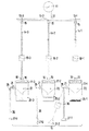
以下、図示の実施形態を参照して本発明に係る分散集塵システムについて、より詳細に説明する。図1は、本発明に係る分散集塵システム10を概念的に示した説明図であり、11は1箇所の吸引装置、12はそれに通じる至近の配管である主配管、13−1、13−2、13−3・・・は複数個の配管分岐部としての吸引用アウトレットを示す。14−1、14−2、14−3・・・は複数個の吸引配管であり、各吸引用アウトレット13−1・・・との接続手段として接続部15を一端に備えており、また、集塵機17−1、17−2、17−3・・・に接続される接続部16を他端に備えている。
Hereinafter, the distributed dust collection system according to the present invention will be described in more detail with reference to the illustrated embodiment. FIG. 1 is an explanatory diagram conceptually showing a distributed
上記の吸引装置11は、例えば大風量吸引ファンから成る。吸引装置11として、本発明を実施する集塵システムの規模に適合した容量の吸引力を発揮するものでなければならないことは当然であるが、そのために使用する大風量吸引ファン等から成る実動部分の台数については1台の場合、2台以上の場合、或いは複数台の中の任意台数を選択する場合などの方式から選択することができる。上記の吸引用アウトレット13・・・は、例えば工場内における壁際などの部位に設置し、配電用のアウトレットいわゆるコンセントと同様に使用するもので、電気装置におけるプラグのようにこれに接続するために接続部15を備えている。
The
図示の例において、18−1、18−2、18−3は吸気制御部であり、図示の例では吸引配管14・・・に配置された風量調節ダンパーから成る。風量調節ダンパーから成る吸気制御部18・・・は、本実施形態の例において各集塵機17・・・を作動させるか否かを決める装置の役割を果たすもので、集塵機17・・・の近くに配置される。なお、他端側の接続部16も上記のプラグとソケットによる結合と同様に接続され、吸引配管14・・・と集塵機17・・・とを吸気可能に接続するものである。
In the illustrated example, 18-1, 18-2, 18-3 are intake control units, and in the illustrated example, are composed of air volume adjusting dampers arranged in the suction pipes 14. The air intake control section 18 comprising air volume adjusting dampers plays a role of a device for determining whether or not to operate each dust collector 17 in the example of the present embodiment, and is close to the dust collectors 17. Be placed. The connecting
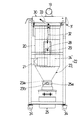
集塵機17は固体吸引及び液体吸引兼用機であり、吸引部35として固体用吸引ノズル37−1、液体用吸引ノズル37−2、微粉塵用吸引ノズル37−3を使用するものとして示されている(図1参照)。本実施形態に例示されている集塵機17は、図2ないし図3に詳細に例示した構成を有するもので、円筒型の集塵機本体20の下流側端部に設けた排気口19と、円筒内部に接線方向から気流を吸引するように外側面に設けた吸引口21とを有し、吸引口21から吸入された気流とともに流れる異物を捕えて分離する分離手段22を内部に備えている。
The dust collector 17 is a solid suction and liquid suction combined machine, and is shown as using a suction nozzle for solid 37-1, a suction nozzle for liquid 37-2, and a suction nozzle for fine dust 37-3 as the
上記分離手段22は、円筒内部に接線方向から気流を吸引し、旋回させ、失速させる過程において異物分離を行うサイクロン方式のために、下向き円錐状に形成されたコーン部23と、サイクロン方式の分離手段を通過した気流を通過させる過程において異物分離を行うためにコーン部23の下流(集塵機本体20内の上部)に設置したフィルター部24を具備している。コーン部23の下端は容器接続のための開口23aとなっており、サイクロン方式で分離された異物はここから落下し、集塵容器25−1、25−2、25−3に集積されることになる。集塵容器25・・・の着脱の手段として容器着脱ハンドル25aが容器側に、ハンドル軸の係合溝23bが開口部側に設けられている。
The separation means 22 is provided with a
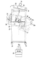
上記フィルター部24は洗浄可能ないわゆるプラスチックフィルターから成り、集塵機本体20の上部開口26から出し入れするように、吊り下げ式構造を以って口縁部に着脱可能に支持されている。図示されている集塵機本体20はそれを内部に配置することができる大きさを有するフレーム部27に回転可能に取り付けられている。フレーム部27にはほぼU字型の軸受け部28が設置されており、軸受け部28に軸支する枢軸29を集塵機本体20の外側面中間部に設け、この軸支部における回転によって集塵機本体20を傾斜させ、フィルター部22を引き出し、本体全体、本体内部及びフィルター部22を洗浄することができるように構成されている。なお、集塵機本体20自体をフレーム部27から取り外すことも可能である。
The
上記フレーム部27の上端には逆洗機構30が配置されている。逆洗機構30は、吸引気流停止時に、吸引気流方向とは逆方向からエアジェットを間欠的にフィルター部24に噴射し、フィルター部24に付着した異物を定期的に空気洗浄する手段である。逆洗機構30はフレーム部27の上端後部に支軸31によって回転可能に取り付けられており、それによって集塵機本体20を傾斜させる際に、上部開口26との抵触を回避している。なお、図2、図3において、32、33はダンパー付き支持アームであり、支持アーム32は集塵機本体20をフレーム部27に支持するとともに集塵機本体20の最大傾斜限界を規定し、支持アーム33は逆洗機構30の上方回転時にそれを支持する。34はキャスターであり、フレーム部27の移動のために設けている。
A
上記集塵機17には吸引部35が接続される。吸引部35は、基端部にて上記集塵機の吸引口21に接続されるホース36と、その先端の吸引ノズルとを備えており、本発明システムの最も末端に位置する。固体、液体、気体に近いものを含む異物を好適に吸引するために、吸引部35は、固体用吸引ノズル37−1、液体用吸引ノズル37−2、微粉塵用吸引ノズル37−3を備えている。吸引部35に接続したホースは分岐管を有して、同一の吸引口21に複数種のノズルを接続するものとすることも可能である。
A
このように構成されている本発明に係る分散集塵システムについて次に説明する。本発明のシステム10では吸引装置11を始動させるとともに、吸気制御部18を操作することによって集塵機17−1、17−2、17−3の使用が可能な状態になる。このとき各接続部15、16の接続されているべきことは言うまでもない。任意の異物、例えば固体の異物を吸引する目的では、吸気制御部18−1を開くことによって、固体用吸引ノズル37−1を使用した吸引作業が可能になる。なお、図示の例のように固体吸引及び液体吸引兼用機17−1、17−2、17−3をそれぞれ専用機として使用する場合には、集塵機として上記のような兼用機を用いなくても良いことは明らかである。
Next, a distributed dust collection system according to the present invention configured as described above will be described. In the
上記の場合、固体の異物は、固体用吸引ノズル18−1から吸引され、集塵機17−1において主としてサイクロン方式による気流との分離作用を受け、コーン部23に接して捕集され、落下して集塵容器25−1に集積される。液体用吸引ノズル37−2を使用した吸引作業においても同様に、主としてサイクロン方式による気流との分離作用を受け、液体の異物はコーン部23に接して捕集され、落下して集塵容器25−2に集積される。また、微粉塵用吸引ノズル37−3から吸引された異物は、その中で質量或いは粒径の大きなものについては主としてサイクロン方式による分離作用を受け、集塵容器25−3に集積される。より小さい微粉塵についてはフィルター部24を気流が通過する際に除塵され、フィルター部24の外面に付着するが、付着した微粉塵は逆洗機構30の作動によってフィルター部24の空気洗浄を行う際に、フィルター外面から剥離して集塵容器25−3に落下する。
In the above case, the solid foreign matter is sucked from the solid suction nozzle 18-1, is subjected to the separation action from the air flow mainly by the cyclone method in the dust collector 17-1, is collected in contact with the
このように本発明のシステム10においては、固体、液体、気体に近い異物を分離するとともに、各々専用の集塵容器に集積することができるものであり、異物によって汚染されるのは固体用吸引ノズル37−1、液体用吸引ノズル37−2、微粉塵用吸引ノズル37−3から各集塵機17−1、17−2、17−3に至る間だけである。よって、それよりも下流の吸引配管14・・・に異物が流れることはなく。従って、吸引配管14・・・に流れる気流は相当程度清浄であるから、吸引配管内部の清掃を行う必要性は著しく低くなる。また、捕集された異物は各集塵容器25−1、25−2、25−3に集積されるので、その後の処理も容易であり、固体と液体等が混じり合うこともなく、回収して再利用することも可能になる。
As described above, in the
すなわち、本発明によれば、
・補修した異物の分別が自動で行われ、廃棄コストが最小限度になる、
・同時に複数箇所で乾式、湿式の集塵作業が可能になる、
・カビや雑菌の繁殖が抑制され、害虫や害獣の進入を防ぎ、衛生面の改善が図れる、
・異物の種類に応じた個別のメインテナンスが可能であり、工場全体の停止は不要、
・メインテナンス時に個別の集塵機への対応で済み、全体を交換する必要がない、
等の利益が得られる。
That is, according to the present invention,
・ Repaired foreign materials are automatically separated, minimizing disposal costs.
・ Dry and wet dust collection work is possible at multiple locations at the same time.
・ Proliferation of mold and other bacteria is suppressed, entry of pests and pests can be prevented, and hygiene can be improved.
・ Individual maintenance according to the type of foreign material is possible, and it is not necessary to stop the entire plant.
・ It is only necessary to handle individual dust collectors during maintenance, and there is no need to replace the entire system.
Etc. are obtained.
10 分散集塵システム
11 吸引装置
12 主配管
13−1・・・ 配管分岐部としての吸引用アウトレット
14−1・・・ 吸引配管
15、16 接続部
17−1・・・ 集塵機
18−1・・・ 吸気制御部
19 排気口
20 集塵機本体
21 吸引口
22 分離手段
23 コーン部
24 フィルター部
25−1 集塵容器26
27 フレーム部
28 軸受け部
29 枢軸
30 逆洗機構
31 支軸
32、33 支持アーム
34 キャスター
35 吸引部
36 ホース
37−1・・・吸引ノズル
DESCRIPTION OF
18-1 ...
27
Claims (4)
主配管に設けられている複数個の配管分岐部、
各配管分岐部に接続される接続部を一端に備えており、かつ、他端にて集塵機に接続される複数個の吸引配管、
吸引口と排気口とを有し、かつ吸引口から吸引された気流に含まれている異物を捕えて気流から分離する分離手段を内蔵し、気流を排気口から吸引配管に排出する上記の集塵機、
基端部にて上記吸引口に接続され、先端部に吸引ノズルを備えた吸引部、
上記吸引装置と集塵機を吸引可能な状態に接続する吸気制御部を具備し、
吸気制御部の操作によって任意の吸引配管に通じる集塵機を作動させるように構成された
分散集塵システム。 One suction device and main piping leading to the suction device;
A plurality of pipe branches provided in the main pipe,
A plurality of suction pipes having a connection part connected to each pipe branch part at one end and connected to the dust collector at the other end,
The above dust collector having a suction port and an exhaust port, and having a built-in separation means for capturing and separating foreign matter contained in the air flow sucked from the suction port, and discharging the air flow from the exhaust port to the suction pipe ,
A suction part connected to the suction port at the base end part and provided with a suction nozzle at the tip part;
An intake control unit for connecting the suction device and the dust collector to a state capable of suction;
A distributed dust collection system configured to operate a dust collector that leads to an arbitrary suction pipe by operating an intake control unit.
Priority Applications (1)
| Application Number | Priority Date | Filing Date | Title |
|---|---|---|---|
| JP2008325927A JP5714796B2 (en) | 2008-12-22 | 2008-12-22 | Distributed dust collection system |
Applications Claiming Priority (1)
| Application Number | Priority Date | Filing Date | Title |
|---|---|---|---|
| JP2008325927A JP5714796B2 (en) | 2008-12-22 | 2008-12-22 | Distributed dust collection system |
Publications (2)
| Publication Number | Publication Date |
|---|---|
| JP2010142784A true JP2010142784A (en) | 2010-07-01 |
| JP5714796B2 JP5714796B2 (en) | 2015-05-07 |
Family
ID=42563767
Family Applications (1)
| Application Number | Title | Priority Date | Filing Date |
|---|---|---|---|
| JP2008325927A Active JP5714796B2 (en) | 2008-12-22 | 2008-12-22 | Distributed dust collection system |
Country Status (1)
| Country | Link |
|---|---|
| JP (1) | JP5714796B2 (en) |
Cited By (4)
| Publication number | Priority date | Publication date | Assignee | Title |
|---|---|---|---|---|
| CN103302064A (en) * | 2013-05-24 | 2013-09-18 | 国家电网公司 | Novel multifunctional sweeping combined device |
| JP2014083590A (en) * | 2012-10-26 | 2014-05-12 | Komatsu Sanki Kk | Thermal cutting machine |
| CN112642233A (en) * | 2020-12-21 | 2021-04-13 | 安徽皖龙环保科技有限公司 | A jetting mechanism for going jetting bag collector |
| CN117883924A (en) * | 2024-03-18 | 2024-04-16 | 中检集团山西宏宇安全科技有限公司 | Dust removal ventilation unit for mine environmental protection |
Citations (4)
| Publication number | Priority date | Publication date | Assignee | Title |
|---|---|---|---|---|
| JPS5479961A (en) * | 1977-12-09 | 1979-06-26 | Tokyo Electric Co Ltd | Device for connecting piping cleaner |
| JPH0747218A (en) * | 1993-08-09 | 1995-02-21 | Nippon Steel Corp | Method for controlling number of rotation of blower by detecting terminal air volume and method for optimum dust collection by controlling terminal damper |
| JPH07159540A (en) * | 1993-12-09 | 1995-06-23 | Toshiba Corp | Dust radiation monitor |
| JPH11128644A (en) * | 1997-10-29 | 1999-05-18 | Toshio Awaji | Dust removing device and dust removal |
-
2008
- 2008-12-22 JP JP2008325927A patent/JP5714796B2/en active Active
Patent Citations (4)
| Publication number | Priority date | Publication date | Assignee | Title |
|---|---|---|---|---|
| JPS5479961A (en) * | 1977-12-09 | 1979-06-26 | Tokyo Electric Co Ltd | Device for connecting piping cleaner |
| JPH0747218A (en) * | 1993-08-09 | 1995-02-21 | Nippon Steel Corp | Method for controlling number of rotation of blower by detecting terminal air volume and method for optimum dust collection by controlling terminal damper |
| JPH07159540A (en) * | 1993-12-09 | 1995-06-23 | Toshiba Corp | Dust radiation monitor |
| JPH11128644A (en) * | 1997-10-29 | 1999-05-18 | Toshio Awaji | Dust removing device and dust removal |
Cited By (5)
| Publication number | Priority date | Publication date | Assignee | Title |
|---|---|---|---|---|
| JP2014083590A (en) * | 2012-10-26 | 2014-05-12 | Komatsu Sanki Kk | Thermal cutting machine |
| CN103302064A (en) * | 2013-05-24 | 2013-09-18 | 国家电网公司 | Novel multifunctional sweeping combined device |
| CN112642233A (en) * | 2020-12-21 | 2021-04-13 | 安徽皖龙环保科技有限公司 | A jetting mechanism for going jetting bag collector |
| CN112642233B (en) * | 2020-12-21 | 2023-01-03 | 安徽皖龙环保科技有限公司 | A jetting mechanism for going jetting bag collector |
| CN117883924A (en) * | 2024-03-18 | 2024-04-16 | 中检集团山西宏宇安全科技有限公司 | Dust removal ventilation unit for mine environmental protection |
Also Published As
| Publication number | Publication date |
|---|---|
| JP5714796B2 (en) | 2015-05-07 |
Similar Documents
| Publication | Publication Date | Title |
|---|---|---|
| JP5714796B2 (en) | Distributed dust collection system | |
| KR101394545B1 (en) | Apparatus for eliminating paint dust | |
| KR20110020504A (en) | Portable dry/wet cyclone dust collector driven by air ejector | |
| US9815252B2 (en) | Wet cyclone dust filtration system | |
| CN107789918A (en) | A kind of air box impulse sack cleaner | |
| JP2012021759A (en) | Air cleaning apparatus | |
| CN110290736B (en) | Filter system and vacuum cleaner comprising a filter system | |
| CN101816536A (en) | Self-cleaning dust-free dust-collecting barrel | |
| JPH1052620A (en) | Dust collector | |
| CN200991624Y (en) | Dust-removal fan | |
| JP3323843B2 (en) | Cleaning equipment | |
| US5758387A (en) | Vacuum ashtray system | |
| CN212998902U (en) | A pulse dust collector for feed additive production | |
| KR100485929B1 (en) | Dust and Offensive Odor Removal System Using in Combination with Rotating Screen and Cyclone Scrubber | |
| JP2004323138A (en) | Paper container classifying/washing/dehydrating conveyor | |
| JP2017055671A (en) | Unseasoned tea leaf washing equipment | |
| CN211635654U (en) | Cloth bag dust removing equipment | |
| CN213595457U (en) | Can clear away ore conveyer belt of dust | |
| CN219292346U (en) | Dust device and dust pelletizing system in advance | |
| CN109876574A (en) | A kind of medium-and-large-sized refuse transfer station deodoration system | |
| CN208711959U (en) | A kind of cyclone separator | |
| CN216644504U (en) | Air purification device of dust-free workshop | |
| CN201150823Y (en) | Trash processing device | |
| CN209108845U (en) | Roof-bolter dust pelletizing system | |
| JP5984509B2 (en) | Hazardous substance removal equipment |
Legal Events
| Date | Code | Title | Description |
|---|---|---|---|
| A621 | Written request for application examination |
Free format text: JAPANESE INTERMEDIATE CODE: A621 Effective date: 20111012 |
|
| A977 | Report on retrieval |
Free format text: JAPANESE INTERMEDIATE CODE: A971007 Effective date: 20120828 |
|
| A131 | Notification of reasons for refusal |
Free format text: JAPANESE INTERMEDIATE CODE: A131 Effective date: 20130723 |
|
| A521 | Request for written amendment filed |
Free format text: JAPANESE INTERMEDIATE CODE: A523 Effective date: 20130924 |
|
| A02 | Decision of refusal |
Free format text: JAPANESE INTERMEDIATE CODE: A02 Effective date: 20131022 |
|
| A521 | Request for written amendment filed |
Free format text: JAPANESE INTERMEDIATE CODE: A523 Effective date: 20140123 |
|
| A911 | Transfer to examiner for re-examination before appeal (zenchi) |
Free format text: JAPANESE INTERMEDIATE CODE: A911 Effective date: 20140131 |
|
| A912 | Re-examination (zenchi) completed and case transferred to appeal board |
Free format text: JAPANESE INTERMEDIATE CODE: A912 Effective date: 20140214 |
|
| A521 | Request for written amendment filed |
Free format text: JAPANESE INTERMEDIATE CODE: A523 Effective date: 20150113 |
|
| A61 | First payment of annual fees (during grant procedure) |
Free format text: JAPANESE INTERMEDIATE CODE: A61 Effective date: 20150312 |
|
| R150 | Certificate of patent or registration of utility model |
Ref document number: 5714796 Country of ref document: JP Free format text: JAPANESE INTERMEDIATE CODE: R150 |
|
| R250 | Receipt of annual fees |
Free format text: JAPANESE INTERMEDIATE CODE: R250 |
|
| R250 | Receipt of annual fees |
Free format text: JAPANESE INTERMEDIATE CODE: R250 |
|
| R250 | Receipt of annual fees |
Free format text: JAPANESE INTERMEDIATE CODE: R250 |
|
| R250 | Receipt of annual fees |
Free format text: JAPANESE INTERMEDIATE CODE: R250 |
|
| R250 | Receipt of annual fees |
Free format text: JAPANESE INTERMEDIATE CODE: R250 |
|
| R250 | Receipt of annual fees |
Free format text: JAPANESE INTERMEDIATE CODE: R250 |
|
| R250 | Receipt of annual fees |
Free format text: JAPANESE INTERMEDIATE CODE: R250 |