JP2010142759A - Flotation apparatus - Google Patents
Flotation apparatus Download PDFInfo
- Publication number
- JP2010142759A JP2010142759A JP2008324347A JP2008324347A JP2010142759A JP 2010142759 A JP2010142759 A JP 2010142759A JP 2008324347 A JP2008324347 A JP 2008324347A JP 2008324347 A JP2008324347 A JP 2008324347A JP 2010142759 A JP2010142759 A JP 2010142759A
- Authority
- JP
- Japan
- Prior art keywords
- foam
- inner cylinder
- sorting
- specific gravity
- liquid
- Prior art date
- Legal status (The legal status is an assumption and is not a legal conclusion. Google has not performed a legal analysis and makes no representation as to the accuracy of the status listed.)
- Pending
Links
Images

Classifications
-
- Y—GENERAL TAGGING OF NEW TECHNOLOGICAL DEVELOPMENTS; GENERAL TAGGING OF CROSS-SECTIONAL TECHNOLOGIES SPANNING OVER SEVERAL SECTIONS OF THE IPC; TECHNICAL SUBJECTS COVERED BY FORMER USPC CROSS-REFERENCE ART COLLECTIONS [XRACs] AND DIGESTS
- Y02—TECHNOLOGIES OR APPLICATIONS FOR MITIGATION OR ADAPTATION AGAINST CLIMATE CHANGE
- Y02W—CLIMATE CHANGE MITIGATION TECHNOLOGIES RELATED TO WASTEWATER TREATMENT OR WASTE MANAGEMENT
- Y02W30/00—Technologies for solid waste management
- Y02W30/50—Reuse, recycling or recovery technologies
- Y02W30/62—Plastics recycling; Rubber recycling
Landscapes
- Separation Of Solids By Using Liquids Or Pneumatic Power (AREA)
- Separation, Recovery Or Treatment Of Waste Materials Containing Plastics (AREA)
Abstract
Description
本発明は、浮遊選別装置、詳しくは、発泡体を含む材料を液体に浮遊させて、発泡体を選別する浮遊選別装置に関する。 The present invention relates to a floating sorting device, and more particularly to a floating sorting device that sorts a foam by floating a material containing the foam in a liquid.
従来より、各種材料の中から、目的の材料を選別するための選別装置が知られている。
例えば、下端が開放される内側サイクロンと、これの外側に設けられ、水を収容する有底の外側サイクロンとを備える比重選別機が提案されている(例えば、特許文献1参照。)。
そして、特許文献1で提案される比重選別機では、球状のPPおよびPETとアルミニウム粒とを含む材料を、内側サイクロン内において渦流となる水に投入し、まず、比重が大きいアルミニウム粒を沈殿させてこれを採取し、次いで、PPおよびPETを内側サイクロンにおいて下降させながら、渦流によって内側サイクロンから外側サイクロンに移動させ浮上させて、これらを選別している。
For example, a specific gravity sorter having an inner cyclone whose lower end is opened and a bottomed outer cyclone that is provided outside and contains water has been proposed (see, for example, Patent Document 1).
And in the specific gravity sorter proposed in
しかるに、廃棄される樹脂などの材料は、発泡ポリスチレンなどの発泡体を含んでおり、かかる発泡体を選別する必要がある。
しかし、特許文献1で提案される比重選別機では、発泡体を選別することは困難である。
本発明の目的は、発泡体を含む材料から、発泡体を効率的、かつ、確実に選別することのできる、浮遊選別装置を提供することにある。
However, materials such as resin to be discarded include foams such as foamed polystyrene, and it is necessary to select such foams.
However, with the specific gravity sorter proposed in
An object of the present invention is to provide a floating sorting device that can efficiently and reliably sort a foam from a material containing the foam.
上記目的を達成するために、本発明の浮遊選別装置は、発泡体を含む材料を液体に浮遊させて、前記発泡体を選別する浮遊選別装置であって、液体を収容するための外側ケーシングと、前記外側ケーシング内に、前記外側ケーシングと連通するように配置され、前記材料を受け入れる内側筒と、前記外側ケーシング内および/または前記内側筒内に設けられ、前記液体を攪拌するための水平回転可能な第1羽根と、前記内側筒内に設けられ、上下移動可能な第2羽根と、前記内側筒内に設けられ、前記内側筒内に材料を供給するための供給部とを備えていることを特徴としている。 In order to achieve the above object, a floating sorting apparatus of the present invention is a floating sorting apparatus that floats a material containing foam in a liquid and sorts the foam, and includes an outer casing for containing the liquid, The inner casing is disposed in the outer casing so as to communicate with the outer casing and receives the material, and is provided in the outer casing and / or the inner casing, and is horizontally rotated to stir the liquid. A first blade capable of moving, a second blade provided in the inner cylinder and movable up and down, and a supply unit provided in the inner cylinder and for supplying material into the inner cylinder. It is characterized by that.
この選別装置では、供給部から内側筒に受け入れられる材料は、第2羽根の上下移動に基づく液体の下方流および上方流によって、上下方向に分離される。
つまり、第2羽根の下方への移動に基づく液体の下方流によって、材料は、一旦、下部に押し下げられる。続いて、比重が極めて小さい発泡体は、相対的に、第2羽根の上方への移動に基づく液体の上方流に追随して、上方に押し上げられて浮上する。
In this sorting apparatus, the material received in the inner cylinder from the supply unit is separated in the vertical direction by the downward flow and upward flow of the liquid based on the vertical movement of the second blade.
That is, the material is once pushed down by the downward flow of the liquid based on the downward movement of the second blade. Subsequently, the foam having an extremely small specific gravity relatively follows the upward flow of the liquid based on the upward movement of the second blade, and is pushed upward to rise.
一方、発泡体以外の材料は、相対的に、第2羽根の上方への移動に基づく液体の上方流に追随せず、内側筒内の下部においてそのまま浮遊する。そして、発泡体以外の材料は、第1羽根の水平回転に基づく水平方向の攪拌に起因する渦流によって、水平回転されながら、水平方向外側へ向かう遠心力によって、内側筒内からそれに連通する外側ケーシングへ移動する。 On the other hand, the material other than the foam relatively does not follow the upward flow of the liquid based on the upward movement of the second blade, and floats as it is in the lower portion in the inner cylinder. The material other than the foam is an outer casing that communicates with it from the inside of the inner cylinder by the centrifugal force that is horizontally rotated by the vortex resulting from the horizontal agitation based on the horizontal rotation of the first blades and that is horizontally rotated. Move to.
そのため、内側筒において浮上する発泡体と、外側ケーシングの発泡体以外の材料とをそれぞれ回収することにより、材料から発泡体を確実に選別することができる。
その結果、簡易な構成により、発泡体を確実に選別することができる。
また、供給部が、内側筒に臨むように外側ケーシング内に設けられている場合には、外側ケーシングにおいて、第1羽根の水平回転に基づく水平方向の攪拌に起因する渦流の円滑な流れを阻害するため、発泡体以外の材料が澱んでしまい、かかる発泡体以外の材料を効率的に回収することができない場合がある。
Therefore, the foam can be reliably selected from the materials by collecting the foam floating in the inner cylinder and the material other than the foam of the outer casing.
As a result, the foam can be reliably selected with a simple configuration.
Further, when the supply unit is provided in the outer casing so as to face the inner cylinder, the smooth flow of the eddy current caused by the horizontal agitation based on the horizontal rotation of the first blade is inhibited in the outer casing. For this reason, materials other than the foam may be stagnated, and materials other than the foam may not be efficiently recovered.
しかし、この浮遊選別装置では、供給部が、内側筒内に設けられているので、外側ケーシングにおける渦流の円滑な流れを維持でき、発泡体以外の材料をその渦流に沿って均一に分散させることができる。そのため、外側ケーシングにおいて、発泡体以外の材料を効率的に回収することができる。
また、本発明の浮遊選別装置では、前記供給部は、上下方向に延び、前記第2羽根と同一軸線上に配置されていることが好適であり、さらに、前記供給部の供給口の縁部が、水平方向に沿って形成されていることが好適である。
However, in this floating sorting apparatus, since the supply unit is provided in the inner cylinder, the smooth flow of the vortex in the outer casing can be maintained, and materials other than the foam can be uniformly dispersed along the vortex. Can do. Therefore, materials other than the foam can be efficiently recovered in the outer casing.
In the floating sorting apparatus according to the present invention, it is preferable that the supply unit extends in the vertical direction and is disposed on the same axis as the second blade, and further, an edge of the supply port of the supply unit Is preferably formed along the horizontal direction.
この浮遊選別装置では、上下方向に延びる供給部が、第2羽根と同一軸線上に配置されているので、供給部が、第2羽根の上下移動を阻害することを防止することができる。そのため、内側筒内において第2羽根の上下移動に基づく液体の下方流および上方流の円滑な流れを維持でき、発泡体を均一に浮遊させることができる。その結果、内側筒において、発泡体を効率的に回収することができる。 In this floating sorting apparatus, the supply portion extending in the vertical direction is disposed on the same axis as the second blade, and therefore, the supply portion can be prevented from obstructing the vertical movement of the second blade. Therefore, the smooth downward flow and upward flow of the liquid based on the vertical movement of the second blade can be maintained in the inner cylinder, and the foam can be floated uniformly. As a result, the foam can be efficiently recovered in the inner cylinder.
また、供給口の縁部が上下方向に傾きをもって形成されている場合には、材料は、供給部の供給口から上下方向に一定幅をもって供給されるため、供給口の下方から供給される材料に含まれる発泡体は、供給口の上方から供給される材料に含まれる発泡体に比べて、第2羽根の下移動に基づく液体の下方流によって下方に移動し易く、外側ケーシングに流出する場合がある。 In addition, when the edge of the supply port is formed with an inclination in the vertical direction, the material is supplied from the supply port of the supply unit with a certain width in the vertical direction, so the material supplied from below the supply port The foam contained in is more likely to move downward due to the downward flow of the liquid based on the downward movement of the second blade than the foam contained in the material supplied from above the supply port, and flows out to the outer casing There is.
しかし、この浮遊選別装置では、供給部の供給口の縁部が、水平方向に沿って形成されているので、材料は、供給部の供給口から上下の区別なく供給されるため、材料の画一的な供給を図ることができる。そのため、上記した発泡体の下方への移動を有効に抑制して、発泡体の外側ケーシングへの流出を有効に抑制することができる。そのため、発泡体をより一層効率的に回収することができる。 However, since the edge of the supply port of the supply unit is formed along the horizontal direction in this floating sorting apparatus, the material is supplied from the supply port of the supply unit without distinction between the upper and lower sides. A single supply can be achieved. Therefore, it is possible to effectively suppress the downward movement of the foam and to effectively suppress the outflow of the foam to the outer casing. Therefore, the foam can be recovered even more efficiently.
また、本発明の浮遊選別装置では、前記第1羽根は、少なくとも前記内側筒内に設けられ、前記供給部の供給口と対向配置されていることが好適である。
この浮遊選別装置では、供給部の供給口から供給される材料を、供給部の供給口と対向配置される第1羽根によって、内側筒内に分散させることができる。そのため、内側筒において、材料から発泡体を効率的に選別することができる。
In the floating sorting device according to the present invention, it is preferable that the first blade is provided at least in the inner cylinder and is disposed to face the supply port of the supply unit.
In this floating sorting apparatus, the material supplied from the supply port of the supply unit can be dispersed in the inner cylinder by the first blades disposed to face the supply port of the supply unit. Therefore, the foam can be efficiently sorted from the material in the inner cylinder.
本発明の浮遊選別装置によれば、簡易な構成により、発泡体を効率的、かつ、確実に選別することができる。 According to the floating sorting apparatus of the present invention, the foam can be sorted efficiently and reliably with a simple configuration.
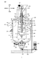
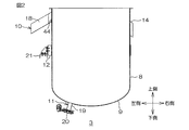
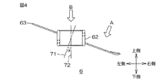
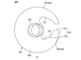
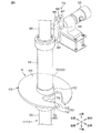
図1は、本発明の浮遊選別装置の一実施形態の正断面図、図2は、外側ケーシングの正断面図、図3は、内側筒の正断面図、図4は、選別部材の正断面図、図5は、図4におけるA矢視図、図6は、クランクおよび支持筒の斜視図である。
また、方向に関する記載は、図1を基準として、紙面右側を「右側」(一方側)、紙面左側を「左側」(他方側)、紙面上側を「上側」、紙面下側を「下側」、紙面手前側を「前側」、紙面奥側を「後側」とする。
1 is a front sectional view of an embodiment of the floating sorting apparatus of the present invention, FIG. 2 is a front sectional view of an outer casing, FIG. 3 is a front sectional view of an inner cylinder, and FIG. 4 is a front section of a sorting member. 5 is a perspective view of the crank and the support cylinder. FIG.
In addition, with respect to the direction, with reference to FIG. 1, the right side of the page is “right side” (one side), the left side of the page is “left side” (the other side), the upper side of the page is “upper side”, and the lower side of the page is “lower side”. The front side of the paper surface is referred to as “front side”, and the back side of the paper surface is referred to as “rear side”.
図1において、この浮遊選別装置1は、発泡体を含む材料を液体2に浮遊させて、発泡体を選別する浮遊選別装置1である。この浮遊選別装置1は、液体2を収容するための外側ケーシング3と、材料を受け入れる内側筒4と、液体2を攪拌するための第1羽根としての上側水平回転羽根5と、液体2を攪拌するための第1羽根としての下側水平回転羽根7と、上下移動可能な第2羽根としての上下移動羽根(選別部)6と、内側筒4内に材料を供給するための供給部17とを備えている。
In FIG. 1, the floating
外側ケーシング3は、第1フレーム21に支持され、浮遊選別装置1の上下方向略中央に配置されており、図1および図2に示すように、上端が開放される有底略円筒形状に形成されている。また、外側ケーシング3は、上下方向に延びる側壁8と、側壁8の下端から連続する底壁9とを一体的に備えている。
側壁8には、小比重取出部10、取付部12および発泡体取出受部14が形成されている。
The
On the
小比重取出部10は、後述する発泡体の選別において浮上する材料(例えば、後述する小比重樹脂)を取り出すために設けられている。具体的には、小比重取出部10は、側壁8の左側上端に配置され、平面視略矩形状に形成されている。小比重取出部10は、上側に向かって開く側断面略コ字形状に形成されており、側壁8の左端から左方斜め下側に向かって連続して突出するように形成されている。
The small specific
また、小比重取出部10により仕切られる空間は、小比重取出室18として形成されている。小比重取出室18は、外側ケーシング3の内部空間(図1において示される後述する第2選別室28)と連通している。
また、小比重取出部10には、第2液面調整ゲート44が設けられている。
第2液面調整ゲート44は、第1液面調整ゲート43(後述)と連動して、第2選別室28の液面を調整するために設けられており、小比重取出部10の右端に、それの下壁から上方に立設する略平板形状に形成されている。
The space partitioned by the small specific
Further, the small specific
The second liquid
取付部12は、側壁8を第1フレーム21に取り付けて固定するために設けられ、側壁8の上下方向途中の外側面に、側壁8の周方向に間隔を隔てて複数設けられている。
発泡体取出受部14は、図1に示すように、後述する発泡体取出管34を収容するために設けられ、側壁8の右側上端に配置されている。発泡体取出受部14は、上側に向かって開く側断面略コ字形状に形成されており、側壁8の右端から右方斜め下側に向かって連続して突出するように形成されている。
The
As shown in FIG. 1, the foam take-
底壁9は、側壁8の下端から径方向中心に向かうに従って下方に突出する正断面湾曲形状に形成されている。
また、底壁9には、前後方向中央の左側に大比重取出部11が設けられている。
大比重取出部11は、発泡体の選別において沈降して沈殿する材料(例えば、後述する大比重樹脂)を取り出すために設けられ、大比重取出管19および開閉弁20を備えている。
The bottom wall 9 is formed in a curved shape with a regular cross section that projects downward from the lower end of the
The bottom wall 9 is provided with a large specific
The large specific
大比重取出管19は、上下方向に延びる略円筒形状に形成されている。また、大比重取出管19は、その上端が、平面視において、底壁9の中心と左側に間隔を隔てて配置され、後述する下側水平回転羽根7の周端より内側に配置されている。
開閉弁20は、大比重取出管19の下端に形成され、大比重取出管19の下端を開閉可能に設けられている。なお、開閉弁20は、自動操作により、一定周期で開閉する。
The large specific
The on-off
内側筒4は、第1フレーム21の上に形成される第2フレーム22の上に形成されるベース24を介して第2フレーム22に支持され、外側ケーシング3内に設けられている。すなわち、内側筒4は、外側ケーシング3の前後方向内側および左右方向内側に、これらと間隔を隔てて配置されている。また、内側筒4は、その軸線が、外側ケーシング3の側壁8の上下方向に沿う軸線と重複するように、つまり、外側ケーシング3と同心状に配置されている。
The
また、内側筒4は、図1および図3に示すように、上端および下端が開放される略円筒形状に形成され、具体的には、下端および上下方向途中では、上方に向かうに従って内径がわずかに小さくなるテーパ形状に形成されるとともに、上端では、略直管形状に形成されている。
また、内側筒4は、外側ケーシング3内に、外側ケーシング3と連通するように配置されている。すなわち、内側筒4の下端が、外側ケーシング3内に臨むように配置されている。また、内側筒4の上端は、外側ケーシング3の上端より上側にやや突出して配置されている。
Further, as shown in FIGS. 1 and 3, the
Further, the
これにより、内側筒4の外側、すなわち、内側筒4と外側ケーシング3との間には、これらにより仕切られる空間(第2選別室)28が形成され、また、内側筒4の内側には、これにより仕切られる空間(第1選別室)27が形成されている。そして、第1選別室27および第2選別室28は、内側筒4の下端である連通口26を介して、互いに連通している。
Thereby, a space (second sorting chamber) 28 partitioned by these is formed outside the
また、内側筒4の上部には、発泡体取出部30および連通窓47が形成されている。
発泡体取出部30は、左側(内側筒4の直径方向内側)に配置される滞留部37と、右側(内側筒4の直径方向外側)に配置される回収部38とを備えている。
滞留部37は、液体2を滞留させるために設けられ、上側に向かって開く側断面視略コ字形状の滞留壁39を備えている。滞留壁39は、内側筒4の右端と連続して形成されており、滞留壁39の下壁は、内側筒4の右端から右方斜め上側に向かって延びるように形成されている。滞留部37において、滞留壁39により仕切られる空間が、滞留室64として形成される。
In addition, a foam take-out
The foam take-out
The staying
回収部38は、上側に向かって開く側断面視略コ字形状の回収壁40を備えている。回収壁40は、滞留壁39の右端と連続して形成されており、回収壁40の下壁が、滞留壁39の右端から右方斜め下側に向かって延びるように形成されている。回収部38において、回収壁40により仕切られる空間が、回収室65として形成される。
そして、内側筒4には、発泡体取出部30の滞留壁39が内側筒4の上部右端に接続されることにより、内側筒4の上端が切り欠かれた、右側面視略矩形状の発泡側開口67が形成されている。
The
The
また、内側筒4において、滞留室64と回収室65とが連通しており、また、滞留室64が、発泡側開口67を介して、第1選別室27(図1参照)と連通している。
また、この発泡体取出部30には、第1液面調整ゲート43が設けられている。
第1液面調整ゲート43は、上記した第2液面調整ゲート44と連動して、第1選別室27の液面を調整するために設けられており、第1液面調整ゲート43は、滞留部37および回収部38との境に、それらの下壁から上方に立設する略平板状に形成されている。
In the
The foam take-out
The first liquid
連通窓47は、第2選別室28と第1選別室27とを一時的に連通させるために設けられている。連通窓47は、内側筒4の左端に、第1液面調整ゲート43と同じ高さに配置され、内側筒4の厚み方向を貫通する側面視略矩形状の開口として形成されている。また、連通窓47には、連通窓47を開閉可能にするためのゲート(図示せず)が設けられている。
The
ゲートは、連通窓47を開閉することにより、第1選別室27および第2選別室28の連通を許容または遮断する。なお、ゲートは、自動操作あるいは手動操作により、内側筒4の周方向に沿ってスライドして開閉する。
また、第1内側筒4の上端には、フランジ46が設けられており、第1内側筒4は、フランジ46の下側のベース24を介して、第2フレーム22に支持されている。
The gate allows or blocks communication between the
A
下側水平回転羽根7は、外側ケーシング3内に設けられており、内側筒4の下方に間隔を隔てて配置されている。より具体的には、下側水平回転羽根7は、第2選別室28の下部に形成されている。
下側水平回転羽根7は、外側ケーシング3および内側筒4の軸線に沿う回転軸52と、回転軸52の下端において支持される下側水平回転羽根部材15とを備えている。
The lower
The lower
回転軸52は、底壁9の中央から上方に向かって延びるように形成されており、具体的には、外側ケーシング3および内側筒4(内側筒4の下部)を貫通し、外側ケーシング3の下部に配置される軸受45によって回転可能に支持されている。詳しくは、回転軸52の上端は、内側筒4の上下方向中央に至っている。また、回転軸52は、内側筒4と同心状に配置されている。
The
また、回転軸52は、下側水平回転羽根7の回転軸および上側水平回転羽根5の回転軸として、下側水平回転羽根7および上側水平回転羽根5に共通して備えられる。また、回転軸52の下端は、プーリ25に接続され、このプーリ25は、第1フレーム21に支持される第1モータ51にベルト33を介して接続されている。第1モータ51は、インバータで変速可能な電動機である。
The rotating
下側水平回転羽根部材15は、回転軸52の下端から径方向外側に延びる複数の弓状羽根を備えている。また、弓状羽根は、底壁9に沿って形成されており、具体的には、底壁9の上面と上下方向にわずかな間隔を隔てて配置されている。
下側水平回転羽根7では、第1モータ51の回転駆動がベルト33およびプーリ25を介して回転軸52に伝達されて、回転軸52が回転されると、下側水平回転羽根部材15の弓状羽根が水平回転される。
The lower horizontal
In the lower
また、下側水平回転羽根部材15は、平面視において回転軸52が時計回りに回転する場合に、その回転方向下流側に向かうに従って上端部から下端部に傾斜している。
上側水平回転羽根5は、内側筒4内に設けられており、上側水平回転羽根5の上側に間隔を隔てて配置されている。また、上側水平回転羽根5は、回転軸52と、回転軸52の上端において支持される上側水平回転羽根部材13とを備えている。
Further, the lower horizontal
The upper
回転軸52は、上記した上側水平回転羽根5および下側水平回転羽根7の水平方向の回転軸であって、下側水平回転羽根部材15および上側水平回転羽根部材13を水平回転可能に支持している。
上側水平回転羽根部材13は、回転軸52の上端から径方向外側に、上記した下側水平回転羽根部材15より短く延びる複数の水平羽根を備えている。上側水平回転羽根5では、第1モータ51の回転駆動がベルト33およびプーリ25を介して回転軸52に伝達されて、上側水平回転羽根部材13の水平羽根が、下側水平回転羽根部材15の弓状羽根とともに、水平回転される。
The rotating
The upper horizontal
また、上側水平回転羽根部材13は、平面視において回転軸52が時計回りに回転する場合に、その回転方向下流側に向かうに従って下端部から上端部に傾斜している。
上下移動羽根6は、平面視において、内側筒4内に設けられており、支持筒16と、支持筒16の下端において支持される選別部材63とを備えている。
支持筒16は、図1および図6に示すように、上下方向に延びる円筒の略直管形状に形成されており、クランク部79(後述)の上下駆動を選別部材63に伝達する。支持筒16は、平面視において、内側筒4の前後方向内側および内側筒4の左右方向内側に、これらと間隔を隔てて配置されている。より具体的には、支持筒16は、その軸線が、内側筒4の上下方向に沿う軸線と重複するように、つまり、内側筒4と同心状に配置されている。すなわち、支持筒16は、回転軸52と同心状に配置されている。また、支持筒16は、内側筒4の上部に配置されている。
Further, the upper horizontal
The vertical moving
As shown in FIGS. 1 and 6, the
また、支持筒16は、その内側(平面視における前後方向内側および左右方向内側)に、シリンダ36(後述)が挿通され、シリンダ36に対して上下移動(摺動)可能となるように配置されている。
また、支持筒16の上端には、クランク部79が設けられている。
クランク部79は、次に説明する第2モータ55の回転運動に基づく回転駆動を、上下駆動に変換し、それを支持筒16に伝達する。クランク部79は、第1アーム84、第2アーム85、第1軸86、第2軸87および第3軸88を備えている。また、クランク部79は、第2モータ55に接続されている。
Further, the
A
The
第1アーム84は、一方向に延びるように形成されており、一端に前後方向に延びる第1軸86が挿通されて固定され、他端に前後方向に延びる第2軸87が挿通されて固定されている。また、第1軸86は、第2モータ55に接続されており、第1アーム84は、第1軸86を中心として回転自在となるように第1軸86を介して第2モータ55に接続されている。
The first arm 84 is formed to extend in one direction, and a
第2アーム85は、一方向に第1アーム84より長く延びるように形成され、一端に第2軸87が回転自在に挿通され、他端に前後方向に延びる第3軸88が回転自在に挿通されている。第2アーム85では、一端が、第1アーム84の他端の回転運動に伴って、揺動されながら、他端が、上下移動する。
第3軸88は、支持筒16に対して相対移動不能となるように固定されており、供給部17のシリンダ36に対して相対的に上下移動可能となっている。
The
The
第2モータ55は、インバータで変速可能な電動機である。
選別部材63は、図1に示すように、内側筒4内に設けられており、水平方向に対して傾斜して設けられている。具体的には、選別部材63は、左側から右側に向かうに従って下方に傾斜して設けられている。すなわち、選別部材63は、図1、図4および図5に示すように、支持筒16の下端に固定されるリング形状の基部62と、基部62から径方向外側に延びる選別板69とを一体的に備えている。
The
As shown in FIG. 1, the sorting
基部62は、図4および図5に示すように、上下方向に延びる円筒形状に形成されている。基部62は、図6に示すように、支持筒16の周りに相対移動不可能に設けられ、かつ、シリンダ36(後述)に対して相対移動可能に設けられている。
選別板69は、図5に示すように、平面視略C字平板形状に形成されている。具体的には、選別板69は、平面視(図4におけるB矢視図)において、略楕円板形状であって、選別板69の平面に直交する方向、つまり、図4におけるA矢視図において、略円板形状に形成され、その右端から、径方向内側に向かって切り欠かれ、後述する渦流の通過を許容する切欠部(許容部)50が形成されている。
As shown in FIGS. 4 and 5, the
As shown in FIG. 5, the sorting
切欠部50は、平面視(図4におけるA矢視図)において、選別板69の右側部分を周方向に分断するように形成されている。また、切欠部50は、選別板69の右側端部から選別板69の軸心(基部62)に向かう径方向途中まで開口される第1開口部73と、第1開口部73の径方向内端から径方向内側に向かって開口される第2開口部74とから形成されている。
The
第1開口部73は、平面視略矩形状に形成されている。
第2開口部74は、第1開口部73から連続し、第1開口部73から径方向内側に向かうに従って第1開口部73から周方向両側に次第に広がる、平面視略C字形状の開口として形成されている。また、第2開口部74は、選別部材63の軸心を中心とする周方向(後述する渦流の流れ方向)に沿って延びるように形成されている。
The
The
また、第2開口部74の前側端部76は、平面視において時計回りに進む方向に向かうに従って、選別部材63の径方向外側端部から径方向内側端部に向かって傾斜している。また、第2開口部74の前側端部76の傾斜面は、径方向外側に向かって湾曲している。
また、第2開口部74の後側端部77は、前側端部76と略対称形状に形成されている。すなわち、第2開口部74の後側端部77は、平面視において反時計回りに進む方向に向かうに従って、選別部材63の径方向外側端部から径方向内側端部に向かって傾斜している。また、第2開口部74の後側端部77の傾斜面は、径方向外側に向かって湾曲している。
Further, the
Further, the
また、第2開口部74の径方向内側端部は、選別板69の径方向内側端部とわずかな間隔を隔てて配置され、基部62の径方向内側端縁と並行している。
さらに詳しくは、選別板69は、図4および図5に示すように、水平方向に対して傾斜して設けられ、すなわち、選別板69の軸線(第1軸線)71が、基部62の軸線(第2軸線)72と交差するように設けられている。すなわち、選別板69が、その左側から右側に向かうに従って、下方に下がるように傾斜して、基部に62に支持されている。
In addition, the radially inner end of the
More specifically, as shown in FIGS. 4 and 5, the sorting
また、選別部材63が傾斜していることから、選別板69の切欠部50を除く部分、つまり、前側部分78および後側部分75は、後述する渦流に沿って上昇する発泡体の上昇を抑制するための抑制部90とされる。
なお、第1軸線71と、第2軸線72とのなす角度αは、例えば、5〜30度、好ましくは、10〜20度である。
Further, since the sorting
The angle α formed by the
また、選別部材63の前側部分78における右側端部は、その径方向外側端縁が上方に屈曲するように形成されている。
そして、選別部材63は、図1の矢印(実線および破線)で示すように、クランク部79からの上下駆動により、支持筒16が上下に往復移動する。また、選別部材63の上下の移動速度は、第2モータ55のインバータ変速により調整される。
Further, the right end portion of the
Then, as shown by the arrows (solid line and broken line) in FIG. 1, the
供給部17は、平面視において、内側筒4内に設けられ、上下方向に延びるように形成されている。供給部17は、スクリューフィーダ31と、シュート35とを備えている。
スクリューフィーダ31は、内側筒4内に材料を供給するための供給機であって、図1に示すように、シリンダ36と、シリンダ36内に収容されるスクリュー32と、スクリュー32を駆動させるための第3モータ41とを備えている。
The
The
シリンダ36は、図1および図6に示すように、前後方向および左右方向に内側筒4と
間隔を隔てて配置されている。詳しくは、シリンダ36は、その軸線が、支持筒16の軸線と重複する(同一軸線上に配置される)ように、つまり、支持筒16と同心状に配置されている。詳しくは、シリンダ36は、支持筒16に摺動自在に挿通されている。
また、シリンダ36は、内側筒4の上端および上下方向途中にわたって形成されている。
As shown in FIGS. 1 and 6, the
Further, the
また、シリンダ36の上端は、内側筒4の上端より上側であって、クランク部79よりも突出するように配置されている。
また、シリンダ36の下端は、材料を内側筒4に供給するための供給口57とされており、この供給口57は、上側水平回転羽根5と上下方向に所定間隔を隔てて(近傍に)対向配置されている。また、供給口57の縁部58は、水平方向に沿って形成されている。
Further, the upper end of the
The lower end of the
スクリュー32は、シリンダ36内において、シリンダ36と同心状に形成されている。スクリュー32は、上下方向において、シリンダ36の全体にわたって設けられており、スクリュー32には、材料を切り出すための羽根29がらせん状に形成されている。スクリュー32の上端には、第3モータ41が接続されている。
第3モータ41は、スクリュー32に回転駆動を伝達して、スクリュー32を回転させるために設けられている。また、第3モータ41は、インバータで変速可能な電動機である。また、第3モータ41は、第2フレーム22の上に形成される第3フレーム23に支持されている。
The
The
シュート35は、スクリューフィーダ31の上部において、材料をスクリューフィーダ31に供給するために設けられている。シュート35は、下方に向かって内径が小さくなる、平面視略台形状の中空状に形成されている。また、シュート35内には、図示しない注液装置が設けられている。
注液装置は、シュート35に投入される材料の状態に応じて、材料に液体(水など)を注液(注水)するように構成されている。
The
The liquid injection device is configured to inject liquid (water) into the material according to the state of the material charged into the
次に、浮遊選別装置1を用いる選別方法について説明する。
この方法では、まず、材料を用意する。
材料としては、例えば、発泡体を含む樹脂などであって、具体的には、一般消費者が廃棄する発泡体を含む廃プラスチック(より具体的には、「容器リサイクル法」に基づくプラスチック回収品)などが挙げられる。
Next, a sorting method using the floating
In this method, first, a material is prepared.
The material is, for example, a resin containing a foam, and specifically, a waste plastic containing a foam discarded by a general consumer (more specifically, a plastic recovery product based on the “Container Recycling Law”) ) And the like.
発泡体としては、例えば、食品トレイなどに使用される、発泡ポリスチレン(発泡PS)など、比重が顕著に小さい発泡樹脂が挙げられる。なお、発泡ポリスチレンとしては、例えば、アルミニウム薄膜などの金属薄膜により被覆された比較的比重の大きい発泡ポリスチレン粒子や、小粒子状(例えば、最大長さが35mm以下)の発泡ポリスチレンなども挙げられる。 Examples of the foam include foamed resin having a remarkably small specific gravity such as foamed polystyrene (foamed PS) used for food trays. Examples of the expanded polystyrene include expanded polystyrene particles having a relatively large specific gravity coated with a metal thin film such as an aluminum thin film, and expanded polystyrene having a small particle shape (for example, a maximum length of 35 mm or less).
発泡体以外の樹脂としては、例えば、ポリエチレン(PE)、ポリプロピレン(PP)などの比重が1よりわずかに小さい樹脂(小比重樹脂)や、例えば、ポリスチレン(例えば、延伸ポリスチレン(OPS)など、発泡PSを除くポリスチレン)、ポリエチレンテレフタレート(PET)、ポリ塩化ビニル(PVC、具体的には、硬質PVCなど)、ポリ塩化ビニリデン(PVDC)、アクリロニトリル・ブタジエン・スチレン共重合樹脂(ABS)などの比重が1より大きい樹脂(大比重樹脂)などが挙げられる。なお、これらの樹脂の形状としては、例えば、粒子状(空隙が形成された粒子状)、フィルム状(皺が形成されたフィルム状)なども含まれる。 Examples of the resin other than the foam include foams such as polyethylene (PE), polypropylene (PP) and the like whose specific gravity is slightly smaller than 1 (small specific gravity resin), and polystyrene (for example, expanded polystyrene (OPS)). Polystyrene except PS), polyethylene terephthalate (PET), polyvinyl chloride (PVC, specifically rigid PVC, etc.), polyvinylidene chloride (PVDC), acrylonitrile / butadiene / styrene copolymer resin (ABS), etc. Resins larger than 1 (high specific gravity resin) and the like can be mentioned. The shape of these resins includes, for example, a particle shape (particle shape with voids formed), a film shape (film shape with wrinkles formed), and the like.
このような小比重樹脂の比重は、例えば、0.9〜0.96であり、大比重樹脂の比重は、例えば、1.1〜1.7である。
材料における各成分の含有割合は、材料100重量部において、例えば、発泡体が3〜8重量部、発泡体以外の材料が85〜95重量部である。より具体的には、材料100重量部において、例えば、発泡PSが5〜6重量部、小比重樹脂が約90重量部、大比重樹脂がそれらの残部である。
The specific gravity of such a low specific gravity resin is, for example, 0.9 to 0.96, and the specific gravity of the large specific gravity resin is, for example, 1.1 to 1.7.
The content ratio of each component in the material is, for example, 3 to 8 parts by weight of the foam and 85 to 95 parts by weight of the material other than the foam in 100 parts by weight of the material. More specifically, in 100 parts by weight of the material, for example, the foamed PS is 5 to 6 parts by weight, the low specific gravity resin is about 90 parts by weight, and the high specific gravity resin is the balance thereof.
また、上記した材料を、必要により、公知の粉砕装置によって、予め粉砕する。この粉砕により、材料の最大長さを、例えば、5〜50mm、好ましくは、10〜30mm、具体的には、25mm程度に調整する。
次いで、この方法では、材料を湿潤状態にする。すなわち、材料に、液体をスプレーなどの散布方法により塗布したり、あるいは、材料を液体に浸漬する。
Further, the above-described materials are pulverized in advance by a known pulverizer as necessary. By this grinding, the maximum length of the material is adjusted to, for example, 5 to 50 mm, preferably 10 to 30 mm, and specifically about 25 mm.
The method then wets the material. That is, the liquid is applied to the material by a spraying method such as spraying, or the material is immersed in the liquid.
液体としては、例えば、水または界面活性剤を含む界面活性剤水溶液などが挙げられる。
界面活性剤としては、例えば、アニオン系界面活性剤、カチオン系界面活性剤、両イオン系界面活性剤、ノニオン系界面活性剤など、公知の界面活性剤が挙げられる。界面活性剤の含有割合は、例えば、界面活性剤水溶液の比重が大比重樹脂の比重以下となるように設定され、具体的には、水100重量部に対して、例えば、1重量部以下、好ましくは、0.5重量部以下(通常、0.3重量部以上)に設定される。界面活性剤の含有割合が上記範囲を超える場合には、界面活性剤水溶液の比重が大比重樹脂の比重より大きくなるので、大比重樹脂を沈降させることができず、大比重樹脂と小比重樹脂とを分離して回収できない場合がある。
Examples of the liquid include water or a surfactant aqueous solution containing a surfactant.
Examples of the surfactant include known surfactants such as an anionic surfactant, a cationic surfactant, a zwitterionic surfactant, and a nonionic surfactant. The content ratio of the surfactant is set, for example, such that the specific gravity of the surfactant aqueous solution is equal to or less than the specific gravity of the high specific gravity resin, specifically, for example, 1 part by weight or less with respect to 100 parts by weight of water, Preferably, it is set to 0.5 parts by weight or less (usually 0.3 parts by weight or more). When the content ratio of the surfactant exceeds the above range, the specific gravity of the surfactant aqueous solution is larger than the specific gravity of the large specific gravity resin, so that the large specific gravity resin cannot be settled. May not be collected separately.
これにより、材料の含水率を、例えば、50重量%以上、好ましくは、70重量%以上、より具体的には、70重量%程度に設定する。材料の含水率が上記範囲にない場合、とりわけ、上記範囲に満たない場合には、材料の表面に空気(気泡)や油膜が付着し易いため、選別において発泡体のみを浮上させにくい場合、具体的には、発泡PSと、PEおよびPPとの浮遊速度を相違させることができない場合がある。 Thereby, the moisture content of the material is set to, for example, 50% by weight or more, preferably 70% by weight or more, more specifically about 70% by weight. If the moisture content of the material is not within the above range, especially if it is less than the above range, air (bubbles) or oil film is likely to adhere to the surface of the material, so it is difficult to lift only the foam in the selection. In some cases, the floating speeds of the foamed PS and PE and PP cannot be made different.
また、浮遊選別装置1に液体2を充填する。液体2は、上記と同様の液体が用いられる。
浮遊選別装置1に液体2を充填するには、外側ケーシング3の上端および/または内側筒4の上端から、第2選別室28および第1選別室27に液体2が充填されるように、液面が滞留部37の右端(第1液面調整ゲート43の上端)の高さおよび小比重取出室18の右端(第2液面調整ゲート44の上端)の高さと同じ高さになるまで、液体2を注入(注液)する。同時に、必要に応じて、第1液面調整ゲート43および第2液面調整ゲート44の高さを調整する。
Further, the floating
In order to fill the floating
また、上下移動羽根6の選別部材63を、図1の破線で示すように、上記高さにまで流入された液体2に浸かる高さ(第1位置)に、クランク部79による支持筒16の下方への移動により、支持筒16によって位置させる。なお、選別部材63は、常には、支持筒16の下方への移動により、第1位置(破線)に位置させ、後述する発泡PSの回収時に、支持筒16の上方への移動により、滞留部37よりも上方の第2位置(実線)に位置させる。
Further, as shown by a broken line in FIG. 1, the sorting
次いで、この方法では、浮遊選別装置1の上側水平回転羽根部材13および下側水平回転羽根部材15を水平回転させる。
すなわち、第1モータ51の回転駆動により、プーリ25を介して上側水平回転羽根部材13および下側水平回転羽根部材15を水平回転させる。
これにより、第1選別室27では、上側水平回転羽根部材13の水平回転によって渦流が発生し、また、第2選別室28では、下側水平回転羽根部材15の水平回転によって渦流が発生する。なお、第1選別室27および第2選別室28における渦流は、平面視において時計回りに渦巻いている。
Next, in this method, the upper horizontal
That is, the upper horizontal
Thus, in the
なお、上側水平回転羽根部材13の周速を、例えば、40〜85m/minに設定し、および下側水平回転羽根部材15の周速を、例えば、100〜200m/minに設定する。
下側水平回転羽根部材15および上側水平回転羽根部材13の周速が上記範囲にない場合には、発泡体を確実に浮上させて、大比重樹脂および小比重樹脂を確実に浮遊させることができない場合がある。そのため、発泡体を効率よく選別することができない場合がある。
The peripheral speed of the upper horizontal
When the peripheral speeds of the lower horizontal
次いで、この方法では、材料を浮遊選別装置1に投入する。
具体的には、まず、材料を、シュート35に投入し、続いて、第3モータ41に基づくスクリュー32の回転により、材料を供給口57から第1選別室27に供給する。これと同時に、材料の内側筒4内への供給の促進と、液体2の補給とを兼ねて、図示しない注液装置から注液する。注液される液体2は、上記した液体2と同様である。
Next, in this method, the material is put into the floating
Specifically, first, the material is put into the
そして、第1選別室27において、供給口57から供給された材料は、供給口57に対向配置される上側水平回転羽根部材13の水平回転により発生する液体2の渦流によって、均一に分離される。
発泡体以外の材料、つまり、小比重樹脂(空隙を有する粒子状またはフィルム状の小比重樹脂を除く)および大比重樹脂は、上側水平回転羽根部材13の水平回転により発生する液体2の渦流によって水平回転されながら沈降する。そして、連通口26において、径方向外側へ向かう遠心力によって、水平方向外側へ向かう遠心力によって、内側筒4内から外側ケーシング3、つまり、第1選別室27から連通口26を介して第2選別室28に移動し、徘徊する。
In the
Materials other than foam, that is, small specific gravity resin (except for particulate or film small specific gravity resin having voids) and large specific gravity resin are caused by the vortex flow of the liquid 2 generated by the horizontal rotation of the upper horizontal
続いて、小比重樹脂および大比重樹脂は、第2選別室28において、その比重の相違により、上下方向に分離される。
つまり、小比重樹脂は、比重が1より小さいことから、遠心力により外側ケーシング3の側壁8に対して押し付けられるように浮上して、小比重取出室18から、取り出される。
Subsequently, the small specific gravity resin and the large specific gravity resin are separated in the vertical direction in the
That is, since the specific gravity is smaller than 1, the low specific gravity resin floats so as to be pressed against the
一方、大比重樹脂は、比重が1より大きいことから、そのまま沈降して、第2選別室28の下部に沈殿する。
下部に沈殿する大比重樹脂は、上側水平回転羽根部材13および下側水平回転羽根部材15の回転を中断、あるいは、上側水平回転羽根部材13の周速および下側水平回転羽根部材15の周速を、それぞれ、例えば、20m/min以下および80m/min以下に低下させること(低速運転)により、大比重取出管19内に沈殿し、開閉弁20が開放されることにより、回収される。
On the other hand, since the high specific gravity resin has a specific gravity greater than 1, it settles as it is and settles in the lower part of the
The large specific gravity resin that settles in the lower part interrupts the rotation of the upper horizontal
一方、比重(見掛け比重)が極めて小さい、発泡体や、空隙が形成された粒子状または皺が形成されたフィルム状の小比重樹脂は、第1選別室27において、上側水平回転羽根部材13による渦流によって水平回転され、それらの浮力によって、内側筒4内において浮上して、選別板69の抑制部90により、上昇が抑制される。そして、発泡体のみが、渦流に沿って移動して切欠部50に至り、渦流の通過とともに、切欠部50を通過して、選別部材63に乗り上げる。
On the other hand, the specific gravity (apparent specific gravity), which is very small in specific gravity (apparent specific gravity), such as a foam or a film-like small specific resin in which voids are formed or a film is formed by the upper horizontal
そのため、選別部材63に乗り上げた発泡体と、外側ケーシング3に移動した発泡体以外の材料とをそれぞれ回収することにより、材料から発泡体を確実に選別することができる。
詳しくは、選別部材63は、支持筒16の下方への移動により、第1位置に位置されている。
Therefore, the foam can be reliably sorted from the material by collecting the foam that has run on the sorting
Specifically, the sorting
選別部材63は、水平方向に対して傾斜しているので、水平方向の渦流に作用することにより、選別部材63の近傍においては、渦流が水平方向に対して傾斜する方向に渦巻く。
そして、切欠部50は、選別板69における下側部分に形成されているので、選別板69の近傍の渦流は、切欠部50において、渦巻く方向が、斜め下方向(前側斜め下方)から斜め上方向(前側斜め上方)に変化する。そのため、切欠部50において、渦流は勢いよく上昇しながら、発泡体に大きな浮遊力を付与するので、かかる発泡体のみが、上側に向かって、渦流とともに通過し易く、発泡体を効率よく回収することができる。
Since the sorting
Since the
さらにまた、渦流の流れ方向に沿って延びる第2開口部74において、渦流とともに渦巻く発泡体の通過を、渦流の流れに沿って効率的に許容することができる。そのため、発泡体を効率よく回収して選別することができる。
また、渦流に沿って流される発泡体は、第2開口部74において、選別板69の径方向外側端部から径方向内側端部に沿いながら、より一層効率よく通過することができる。そのため、材料から発泡体をより一層効率的に選別することができる。
Furthermore, in the
In addition, the foam flowing along the vortex can pass through the
次いで、クランク部79による支持筒16の上方への移動により、選別部材63を上方に移動させる。
具体的には、選別部材63を、液体2の液面より上方の高さ(第2位置)に移動させる(図1の実線)。これにより、選別部材63に乗り上げた発泡体は、選別部材63の上方向の移動および選別部材63の傾斜に基づいて、回収室65に放り出される(掬い上げられる)。なお、選別部材63に乗り上げた発泡体は、選別板69の前側部分78の右側端部が上側に屈曲していることから、選別板69の前側部分78から径方向外側に向かってこぼれることが防止される。
Next, the sorting
Specifically, the sorting
なお、選別部材63の上下の往復移動速度は、例えば、5〜25m/min、好ましくは、5〜10m/minに設定される。
その後、上記と同様に、選別部材63を上下方向に繰り返し往復移動させることにより、継続的に発泡体を回収する。選別部材63の往復移動の時間間隔(インターバル)は、例えば、5〜40秒/1回(1往復)、具体的には、20秒/回(1往復)程度である。
The vertical reciprocating speed of the sorting
Thereafter, the foam is continuously collected by repeatedly reciprocating the sorting
そして、この浮遊選別装置1では、選別部材63を上下に往復移動させることにより、選別部材63に乗り上げた発泡体を、選別部材63から確実に分離させて、発泡体を効率よく回収することができる。
その結果、簡易な構成により、発泡体を確実に選別することができる。
なお、供給部17が、内側筒4の上下方向途中に臨むように外側ケーシング3内に設けられている場合(具体的には、スクリューフィーダ31のシリンダ36が外側ケーシング3の上端から内側筒4の上下方向中央に向かって斜めに延び、第2選別室28を貫通するように設けられる場合)には、第2選別室28において、水平回転羽根部材61の水平回転に基づく水平方向の攪拌に起因する渦流の円滑な流れを阻害する場合がある。
In the floating
As a result, the foam can be reliably selected with a simple configuration.
When the
つまり、第2選別室28における供給部17の上側において、流れが緩やかな部分を生じ、そのため、浮遊する小比重樹脂が澱んでしまい、かかる小比重樹脂を効率的に回収することができない場合がある。
とりわけ、浮遊選別装置1を長時間運転する場合には、小比重樹脂の澱みが顕著となり、小比重樹脂の回収率が低下する場合がある。
That is, in the
In particular, when the floating
しかし、この浮遊選別装置1では、供給部17が、内側筒4内に設けられているので、外側ケーシング3における渦流の円滑な流れを維持することができ、小比重樹脂をその渦流に沿って均一に分散させることができる。そのため、外側ケーシング3において、小比重樹脂、ひいては、発泡体を効率的に回収することができる。
なお、この浮遊選別装置1において、発泡体取出部30は、第2選別室28の上部に形成されていることから、第2選別室28における渦流は、発泡体取出部30の下側を流れる。そのため、発泡体取出部30の下側には、小比重樹脂が浮遊せず、上記した小比重樹脂の澱みは防止されている。
However, in this floating sorting
In the floating
なお、発泡体のうち、小粒子(例えば、最大長さが4mm以下)状の発泡体は、得られる浮力が小さいため、第1選別室27において上昇しにくく、上下移動羽根6の下方への移動によって沈降し、その後、連通口26を介して第2選別室28に漏れ易い場合がある。
その場合には、ゲート(図示せず)をスライドして、連通窓47を開放させて、第1選別室27と第2選別室28とを一時的に連通させることによって、第2選別室28において浮上する発泡体を、径方向外側から径方向内側に向かう渦流とともに、第1選別室27に移動させることができる。その後、選別部材63の上下方向の移動によって、移動させた発泡体を回収することができる。そのため、発泡体をより一層効率よく回収することができる。
Of the foams, the foams in the form of small particles (for example, the maximum length is 4 mm or less) are less likely to rise in the
In this case, the
なお、上記した説明では、供給部17を、内側筒4内において、上下方向に延び、支持筒16と同一軸線上に配置しているが、供給部17の配置は、内側筒4内であれば、これに限定されない。例えば、図示しないが、供給部17を、内側筒4内において、上下斜め方向に配置したり、あるいは、上下方向に延び、かつ、内側筒4内における前後方向および左右方向のいずれか一端に、配置して、支持筒16の軸線と相違する軸線上に配置することもできる。
In the above description, the
好ましくは、供給部17を、上下方向に延び、前後方向および左右方向中央における支持筒16と同一軸線上に配置する。これにより、供給部17が、支持筒59の上下移動に基づく選別板69の上下移動を阻害することを防止することができる。そのため、内側筒4内において選別板69の上下移動に基づく液体2の下方流および上方流の円滑な流れを維持でき、発泡体を均一に浮遊させることができる。その結果、内側筒4において、発泡体を効率的に回収することができる。
Preferably, the
さらに、上記した説明では、供給部17の供給口57の縁部58を、水平方向に沿って形成しているが、例えば、図示しないが、上下方向に傾きをもって形成することもできる。
好ましくは、供給部17の供給口57の縁部58を水平方向に沿って形成する。
供給部17の供給口57の縁部58を上下方向に傾きをもって形成する場合には、材料は、供給部17の供給口57から上下方向に一定幅をもって供給される。そのため、供給口57の下方から供給される材料に含まれる発泡体(上記した小粒子状の発泡体)は、供給口57の上方から供給される材料に含まれる発泡体に比べて、上下移動羽根6の下移動に基づく水の下方流によって下方に沈降し易く、第2選別室28に漏れる場合がある。
Furthermore, in the above description, the
Preferably, the
When the
しかしながら、供給部17の供給口57の縁部58を、水平方向に沿って形成することにより、材料は、供給部17の供給口57から上下の区別なく供給されるため、材料の画一的な供給を図ることができる。
そのため、上記した発泡体(小粒子状の発泡体)の、上下移動羽根6の下移動に基づく水の下方流による沈降を、有効に抑制して、第2選別室28への流出を有効に抑制することができる。その結果、連通窓47を開放させることなく、簡易な方法で、第1選別室28において、発泡体をより一層効率的に回収することができる。
However, by forming the
For this reason, the above-described foam (small particle foam) is effectively suppressed from sinking due to the downward flow of water based on the downward movement of the up and down moving
また、上記した説明では、液体を攪拌させるための第1羽根として、上側水平回転羽根5および下側水平回転羽根7の2つを設けたが、例えば、図示しないが、上記の2つのうちいずれか一方のみを設けることもできる。
好ましくは、少なくとも上側水平回転羽根5を設ける。具体的には、上側水平回転羽根5のみを設けるか、あるいは、上側水平回転羽根5および下側水平回転羽根7の両方を設ける。
In the above description, the first
Preferably, at least the upper
少なくとも上側水平回転羽根5を設けることにより、上側水平回転羽根5によって、供給部17の供給口57から供給される材料を、第1選別室27(内側筒4内)に均一に分散させることができる。そのため、内側筒4において、材料から発泡体を効率的に選別することができる。
さらに好ましくは、上側水平回転羽根5および下側水平回転羽根7の両方を設ける。両方の羽根を設けることによって、上側水平回転羽根5により、供給口57から供給される材料を均一に分散させながら、内側筒4内に渦流を確実に発生させるとともに、下側水平回転羽根7により、外側ケーシング3内に渦流を確実に発生させることができる。
By providing at least the upper
More preferably, both the upper
また、上記した説明では、供給部として、スクリューフィーダ31を備える供給部17を例示したが、例えば、図示しないが、ピストンおよびピストンを収容するシリンダ36を備える供給部17によって、供給口57から材料を押し出して供給すことができる。さらには、スクリュー32および第3モータ41を備えず、シリンダ36からなる略直管状の供給部17に、材料を直接投入して、供給口57から材料を供給することもできる。
In the above description, the
また、上記した浮遊選別方法では、浮遊選別装置1を1つ用いたが、例えば、図示しないが、複数の浮遊選別装置1を直列に多段で接続することができる。このようにすれば、発泡体の選別の精度を向上させることができる。
In the above floating sorting method, one floating
1 浮遊選別装置
2 液体
3 外側ケーシング
4 内側筒
5 上側水平回転羽根
6 上下移動羽根
7 下側水平回転羽根
17 供給部
57 供給口
58 縁部
DESCRIPTION OF
Claims (4)
液体を収容するための外側ケーシングと、
前記外側ケーシング内に、前記外側ケーシングと連通するように配置され、前記材料を受け入れる内側筒と、
前記外側ケーシング内および/または前記内側筒内に設けられ、前記液体を攪拌するための水平回転可能な第1羽根と、
前記内側筒内に設けられ、上下移動可能な第2羽根と、
前記内側筒内に設けられ、前記内側筒内に材料を供給するための供給部と
を備えていることを特徴とする、浮遊選別装置。 A floating sorting device that floats a material containing foam in a liquid and sorts the foam,
An outer casing for containing the liquid;
An inner cylinder disposed within the outer casing and in communication with the outer casing for receiving the material;
A first blade provided in the outer casing and / or the inner cylinder and capable of horizontally rotating for stirring the liquid;
A second blade provided in the inner cylinder and movable up and down;
A floating sorting device provided in the inner cylinder and provided with a supply unit for supplying material into the inner cylinder.
Priority Applications (1)
| Application Number | Priority Date | Filing Date | Title |
|---|---|---|---|
| JP2008324347A JP2010142759A (en) | 2008-12-19 | 2008-12-19 | Flotation apparatus |
Applications Claiming Priority (1)
| Application Number | Priority Date | Filing Date | Title |
|---|---|---|---|
| JP2008324347A JP2010142759A (en) | 2008-12-19 | 2008-12-19 | Flotation apparatus |
Publications (1)
| Publication Number | Publication Date |
|---|---|
| JP2010142759A true JP2010142759A (en) | 2010-07-01 |
Family
ID=42563745
Family Applications (1)
| Application Number | Title | Priority Date | Filing Date |
|---|---|---|---|
| JP2008324347A Pending JP2010142759A (en) | 2008-12-19 | 2008-12-19 | Flotation apparatus |
Country Status (1)
| Country | Link |
|---|---|
| JP (1) | JP2010142759A (en) |
Cited By (3)
| Publication number | Priority date | Publication date | Assignee | Title |
|---|---|---|---|---|
| JP2012196612A (en) * | 2011-03-18 | 2012-10-18 | Mitsubishi Electric Corp | Sorter of specific gravity |
| CN108745611A (en) * | 2018-04-08 | 2018-11-06 | 共同科技开发有限公司 | A kind of tobacco seed water choosing device |
| JP2019522577A (en) * | 2016-06-06 | 2019-08-15 | プレビエロ エンネ ソシエタ ア レスポンサビリタ リミタータ | Method and apparatus for cleaning and separating plastic materials |
-
2008
- 2008-12-19 JP JP2008324347A patent/JP2010142759A/en active Pending
Cited By (4)
| Publication number | Priority date | Publication date | Assignee | Title |
|---|---|---|---|---|
| JP2012196612A (en) * | 2011-03-18 | 2012-10-18 | Mitsubishi Electric Corp | Sorter of specific gravity |
| JP2019522577A (en) * | 2016-06-06 | 2019-08-15 | プレビエロ エンネ ソシエタ ア レスポンサビリタ リミタータ | Method and apparatus for cleaning and separating plastic materials |
| JP6993354B2 (en) | 2016-06-06 | 2022-01-13 | プレビエロ エンネ ソシエタ ア レスポンサビリタ リミタータ | Methods and equipment for cleaning and separating plastic materials |
| CN108745611A (en) * | 2018-04-08 | 2018-11-06 | 共同科技开发有限公司 | A kind of tobacco seed water choosing device |
Similar Documents
| Publication | Publication Date | Title |
|---|---|---|
| CN100448548C (en) | A separate size flotation device | |
| JP5704768B2 (en) | Waste plastic separation and recovery apparatus and separation and recovery method thereof | |
| JP2003126727A (en) | Method and apparatus for sorting plastic waste | |
| CN110087774A (en) | For cleaning and the method and apparatus of separating plastic material | |
| ZA200507421B (en) | Auxiliary agitator for a flotation device | |
| US20040178152A1 (en) | System and method of gas energy management for particle flotation and separation | |
| US11220026B2 (en) | Washing and separating method and apparatus for plastics materials | |
| JP2010142759A (en) | Flotation apparatus | |
| US20160346791A1 (en) | Flotation cell and system for separating hydrophobic particles from a mixture of particles and liquid | |
| JP2009285645A (en) | Flotation apparatus | |
| US10093036B2 (en) | Process for separating materials | |
| AU2011229681B2 (en) | Centrifugal separator apparatus | |
| BR112016007468B1 (en) | Improved magnetic density separation device and method | |
| US20100078363A1 (en) | Process and apparatus for separating solid mixtures | |
| JP2009160531A (en) | Flotation separation apparatus and flotation separation method | |
| CN210906568U (en) | Ore feeding pipe adjusting device of flotation machine | |
| WO2004088277A2 (en) | System and method of gas energy management for particle flotation and separation | |
| JP2005313058A (en) | Oil-water separator | |
| RU139826U1 (en) | DEVICE FOR SEPARATION OF FINE-WASTE WASTE BY THE HYDRA HYDROFLOTATION METHOD | |
| JP2019188288A (en) | Specific gravity fractionation device for resin and specific gravity fractionation method for resin | |
| CA3152124A1 (en) | Methods and systems for high throughput separation of materials using stratification and rotational motion | |
| CN203678405U (en) | Separating funnel assembly for extraction | |
| JP2003164774A (en) | Washing and specific gravity separation apparatus in liquid | |
| CA2541998A1 (en) | Grit trap | |
| KR20190005269A (en) | Gravity Separating Apparatus for Waste Plastic with Forced Throwing Way |