JP2010142744A - Method of evaluating discharge performance of droplet discharge head, method of deciding maintenance timing of droplet discharge head, method of predicting and deciding service life of droplet discharge head and apparatus for evaluating discharge perormance of droplet discharge head - Google Patents
Method of evaluating discharge performance of droplet discharge head, method of deciding maintenance timing of droplet discharge head, method of predicting and deciding service life of droplet discharge head and apparatus for evaluating discharge perormance of droplet discharge head Download PDFInfo
- Publication number
- JP2010142744A JP2010142744A JP2008323634A JP2008323634A JP2010142744A JP 2010142744 A JP2010142744 A JP 2010142744A JP 2008323634 A JP2008323634 A JP 2008323634A JP 2008323634 A JP2008323634 A JP 2008323634A JP 2010142744 A JP2010142744 A JP 2010142744A
- Authority
- JP
- Japan
- Prior art keywords
- discharge
- head
- discharge amount
- droplet
- functional liquid
- Prior art date
- Legal status (The legal status is an assumption and is not a legal conclusion. Google has not performed a legal analysis and makes no representation as to the accuracy of the status listed.)
- Withdrawn
Links
- 238000000034 method Methods 0.000 title claims description 28
- 238000012423 maintenance Methods 0.000 title claims description 25
- 239000007788 liquid Substances 0.000 claims abstract description 138
- 238000011156 evaluation Methods 0.000 claims abstract description 73
- 230000008859 change Effects 0.000 claims abstract description 51
- 238000005259 measurement Methods 0.000 claims abstract description 43
- 238000007689 inspection Methods 0.000 description 46
- 239000000758 substrate Substances 0.000 description 24
- 239000011521 glass Substances 0.000 description 21
- 230000008569 process Effects 0.000 description 8
- 238000012545 processing Methods 0.000 description 7
- 238000003384 imaging method Methods 0.000 description 5
- 230000007246 mechanism Effects 0.000 description 5
- 238000012360 testing method Methods 0.000 description 5
- 238000005286 illumination Methods 0.000 description 4
- 238000003860 storage Methods 0.000 description 4
- 230000002950 deficient Effects 0.000 description 3
- 238000009434 installation Methods 0.000 description 3
- 238000010586 diagram Methods 0.000 description 2
- 238000004519 manufacturing process Methods 0.000 description 2
- 239000011295 pitch Substances 0.000 description 2
- 230000002123 temporal effect Effects 0.000 description 2
- 230000015572 biosynthetic process Effects 0.000 description 1
- 239000003086 colorant Substances 0.000 description 1
- 238000007599 discharging Methods 0.000 description 1
- 238000012854 evaluation process Methods 0.000 description 1
- 238000005429 filling process Methods 0.000 description 1
- 230000004886 head movement Effects 0.000 description 1
- 230000008531 maintenance mechanism Effects 0.000 description 1
- 239000000463 material Substances 0.000 description 1
- 239000008239 natural water Substances 0.000 description 1
- 238000011084 recovery Methods 0.000 description 1
- 239000011347 resin Substances 0.000 description 1
- 229920005989 resin Polymers 0.000 description 1
- 239000004575 stone Substances 0.000 description 1
- 230000008719 thickening Effects 0.000 description 1
Images

Landscapes
- Coating Apparatus (AREA)
- Ink Jet (AREA)
- Application Of Or Painting With Fluid Materials (AREA)
Abstract
【課題】各吐出ノズルの吐出量の変化量を評価基準として、液滴吐出ヘッドの経時的変化を評価することができる。
【解決手段】複数の吐出ノズル21の吐出量を測定する第1吐出量測定工程と、第1吐出量測定工程から一定期間経過後、複数の吐出ノズル21の吐出量を測定する第2吐出量測定工程と、各吐出ノズル21において、第2吐出量測定工程で測定した吐出量から、第1吐出量測定工程で測定した吐出量を減算した値を、それぞれ算出する減算算出工程と、算出した各値の標準偏差を算出する標準偏差算出工程と、標準偏差に基づいて、機能液滴吐出ヘッド1の経時的変化を評価するヘッド評価工程と、を備えた。
【選択図】図9The change over time of a droplet discharge head can be evaluated using the change amount of the discharge amount of each discharge nozzle as an evaluation criterion.
A first discharge amount measuring step for measuring discharge amounts of a plurality of discharge nozzles, and a second discharge amount for measuring discharge amounts of a plurality of discharge nozzles after a lapse of a certain period from the first discharge amount measurement step. A subtracting calculation step for calculating a value obtained by subtracting the discharge amount measured in the first discharge amount measurement step from the discharge amount measured in the second discharge amount measurement step at each discharge nozzle 21; A standard deviation calculating step for calculating a standard deviation of each value, and a head evaluation step for evaluating a change with time of the functional liquid droplet ejection head 1 based on the standard deviation.
[Selection] Figure 9
Description
本発明は、複数の吐出ノズルを有する液滴吐出ヘッドの吐出性能に関する経時的変化を評価する液滴吐出ヘッドの吐出性能評価方法、液滴吐出ヘッドのメンテナンス時機決定方法、液滴吐出ヘッドの寿命予測決定方法および液滴吐出ヘッドの吐出性能評価装置に関するものである。 The present invention relates to a method for evaluating a discharge performance of a droplet discharge head for evaluating a change over time in a discharge performance of a droplet discharge head having a plurality of discharge nozzles, a method for determining a maintenance timing of a droplet discharge head, and a life of the droplet discharge head. The present invention relates to a prediction determination method and a discharge performance evaluation apparatus for a droplet discharge head.
従来、この種の液滴吐出ヘッドの吐出性能評価方法として、各吐出ノズルから測定吐出を実施して着弾ドットを形成する工程と、形成した着弾ドットを画像認識することで、各吐出ノズルの吐出の有無および着弾位置のズレ量を検査する工程と、その検査結果に基づいて、液滴吐出ヘッドの経時的変化を評価する工程と、を備えたものが知られている。
ところで、吐出の有無や着弾位置のズレ量のみならず、各吐出ノズルの吐出量の変化量も、液滴吐出ヘッドの吐出性能に影響を与える要素である。例えば、経時的変化によって、吐出ノズルの吐出量が変化し、隣接する吐出ノズルの吐出量に差異が出てしまうと、スジムラが発生してしまい、精度良く描画処理を行うことができない。しかしながら、上記の吐出性能評価方法では、吐出量の変化量を基準に評価を行うことができないため、液滴吐出ヘッドの経時的変化を正確に評価することができないという問題があった。 Incidentally, not only the presence / absence of ejection and the amount of deviation of the landing position, but also the amount of change in the ejection amount of each ejection nozzle is an element that affects the ejection performance of the droplet ejection head. For example, when the discharge amount of the discharge nozzle changes due to a change over time and a difference occurs in the discharge amount of the adjacent discharge nozzles, unevenness occurs, and the drawing process cannot be performed with high accuracy. However, in the above-described ejection performance evaluation method, there is a problem that it is not possible to accurately evaluate the change with time of the droplet ejection head because the evaluation cannot be performed based on the variation in the ejection amount.
本発明は、各吐出ノズルの吐出量の変化量を評価基準として、液滴吐出ヘッドの経時的変化を評価することができる液滴吐出ヘッドの吐出性能評価方法、液滴吐出ヘッドのメンテナンス時機決定方法、液滴吐出ヘッドの寿命予測決定方法および液滴吐出ヘッドの吐出性能評価装置を提供することを課題としている。 The present invention relates to a method for evaluating a discharge performance of a droplet discharge head capable of evaluating a change over time of the droplet discharge head using an amount of change in the discharge amount of each discharge nozzle as an evaluation criterion, and determining a maintenance timing of the droplet discharge head. It is an object of the present invention to provide a method, a method for determining a lifetime of a droplet discharge head, and an apparatus for evaluating the discharge performance of a droplet discharge head.
本発明の液滴吐出ヘッドの吐出性能評価方法は、複数の吐出ノズルを有する液滴吐出ヘッドの吐出性能に関する経時的変化を評価する液滴吐出ヘッドの吐出性能評価方法であって、複数の吐出ノズルの吐出量を測定する第1吐出量測定工程と、第1吐出量測定工程から一定期間経過後、複数の吐出ノズルの吐出量を測定する第2吐出量測定工程と、各吐出ノズルにおいて、第2吐出量測定工程で測定した吐出量から、第1吐出量測定工程で測定した吐出量を減算した値を、それぞれ算出する減算算出工程と、算出した各値の標準偏差を算出する標準偏差算出工程と、標準偏差に基づいて、液滴吐出ヘッドの経時的変化を評価するヘッド評価工程と、を備えたことを特徴とする。 The method for evaluating the discharge performance of a droplet discharge head according to the present invention is a method for evaluating the discharge performance of a droplet discharge head for evaluating a change over time related to the discharge performance of a droplet discharge head having a plurality of discharge nozzles. In each discharge nozzle, a first discharge amount measurement step for measuring the discharge amount of the nozzle, a second discharge amount measurement step for measuring the discharge amount of a plurality of discharge nozzles after a lapse of a certain period from the first discharge amount measurement step, A subtraction calculation step for calculating a value obtained by subtracting the discharge amount measured in the first discharge amount measurement step from the discharge amount measured in the second discharge amount measurement step, and a standard deviation for calculating a standard deviation of each calculated value. And a head evaluation step for evaluating a change with time of the droplet discharge head based on the standard deviation.
本発明の液滴吐出ヘッドの吐出性能評価装置は、複数の吐出ノズルを有する液滴吐出ヘッドの吐出性能に関する経時的変化を評価する液滴吐出ヘッドの吐出性能評価装置であって、複数の吐出ノズルの吐出量を測定する吐出量測定手段と、液滴吐出ヘッドおよび吐出量測定手段を制御する制御手段と、を備え、制御手段は、吐出量測定手段により、複数の吐出ノズルの吐出量を測定する第1吐出量測定動作と、吐出量測定手段により、第1吐出量測定動作から一定期間経過後、複数の吐出ノズルの吐出量を測定する第2吐出量測定動作と、各吐出ノズルにおいて、第2吐出量測定動作で測定した吐出量から、第1吐出量測定動作で測定した吐出量を減算した値を、それぞれ算出する減算算出動作と、算出した各値の標準偏差を算出する標準偏差算出動作と、標準偏差に基づいて、液滴吐出ヘッドの経時的変化を評価するヘッド評価動作と、を実行することを特徴とする。 A discharge performance evaluation apparatus for a droplet discharge head according to the present invention is a discharge performance evaluation apparatus for a droplet discharge head that evaluates a change over time regarding the discharge performance of a droplet discharge head having a plurality of discharge nozzles. A discharge amount measuring means for measuring the discharge amount of the nozzle, and a control means for controlling the droplet discharge head and the discharge amount measuring means. The control means controls the discharge amounts of the plurality of discharge nozzles by the discharge amount measuring means. A first discharge amount measuring operation for measuring, a second discharge amount measuring operation for measuring the discharge amount of a plurality of discharge nozzles after a certain period of time has elapsed from the first discharge amount measuring operation by the discharge amount measuring means, and in each discharge nozzle A subtraction calculation operation for calculating a value obtained by subtracting the discharge amount measured by the first discharge amount measurement operation from the discharge amount measured by the second discharge amount measurement operation, and a standard for calculating the standard deviation of each calculated value side And calculating operation, based on the standard deviation, and executes a head evaluation operation to evaluate the time course of the droplet discharge head.
これらの構成によれば、各吐出ノズルにおいて、一定期間経過前の吐出量から経過後の吐出量の差(変化量)を算出し、その各変化量の標準偏差を算出して、評価の基準とする。この各変化量の標準偏差は、当該変化量のバラツキ量の指標と成る数値であるが、吐出量の変化量はプラスマイナス双方に且つ均等にバラつくため、結果的に吐出量の変化量の指標と成る数値となる。すなわち、上記標準偏差を評価基準とすることで、吐出量の変化量を基準として評価を実施することができるため、液滴吐出ヘッドの経時的変化を正確に評価することができる。また、変化量を数値化して、評価基準とすることができるため、液滴吐出ヘッドの経時的変化を容易に比較することができる。さらに、吐出量の変化量の指標と成る数値であると共に、変化量のバラツキ量の指標と成る数値を用いることで、変化量のみならず、変化量のバラツキをも基準として、評価を行うことができる。 According to these configurations, in each discharge nozzle, the difference (change amount) in the discharge amount after the lapse of time from the discharge amount before the lapse of a certain period is calculated, the standard deviation of each change amount is calculated, and the evaluation standard And The standard deviation of each change amount is a numerical value that serves as an index of the variation amount of the change amount. However, since the change amount of the discharge amount varies both positively and negatively, as a result, the change amount of the discharge amount is changed. It becomes a numerical value that serves as an index. That is, by using the standard deviation as an evaluation criterion, the evaluation can be performed on the basis of the change amount of the ejection amount, so that the change with time of the droplet ejection head can be accurately evaluated. Further, since the amount of change can be quantified and used as an evaluation criterion, it is possible to easily compare changes with time of the droplet discharge heads. In addition to using numerical values that serve as indicators of changes in the amount of discharge and numerical values that serve as indicators of the amount of variation in the amount of change, evaluation is performed based not only on the amount of change but also on the variation in the amount of change. Can do.
上記の液滴吐出ヘッドの吐出性能評価方法において、第1吐出量測定工程および第2吐出量測定工程は、複数の吐出ノズルから測定吐出を実施して、複数の吐出ノズル分の複数の着弾ドットを形成する着弾ドット形成工程と、形成した複数の着弾ドットの体積をそれぞれ測定することで、複数の吐出ノズルの吐出量を測定する体積測定工程と、をそれぞれ備えたことが好ましい。 In the discharge performance evaluation method for the droplet discharge head, the first discharge amount measurement step and the second discharge amount measurement step perform measurement discharge from a plurality of discharge nozzles, and a plurality of landing dots for the plurality of discharge nozzles. It is preferable that the method includes a landing dot forming step for forming a plurality of droplets, and a volume measuring step for measuring the discharge amounts of the plurality of discharge nozzles by measuring the volumes of the plurality of formed landing dots, respectively.
この構成によれば、複数の吐出ノズルを同時に吐出駆動して、吐出量を測定することができるため、複数の吐出ノズルを1ノズルずつ吐出駆動して、吐出量を測定するものと比較して、複数の吐出ノズルの吐出量を容易に測定することができる。 According to this configuration, since a plurality of discharge nozzles can be simultaneously driven to measure the discharge amount, the plurality of discharge nozzles can be driven to discharge one nozzle at a time and compared with a method for measuring the discharge amount. The discharge amounts of the plurality of discharge nozzles can be easily measured.
この場合、標準偏差の3倍の数値または標準偏差の6倍の数値に基づいて、液滴吐出ヘッドの経時的変化を評価することが好ましい。 In this case, it is preferable to evaluate the temporal change of the droplet discharge head based on a value three times the standard deviation or a value six times the standard deviation.
この構成によれば、標準的に用いられる標準偏差の3倍(3σ)や標準偏差の6倍(6σ)の数値を、評価基準とするため、液滴吐出ヘッドの経時的変化が評価しやすくなる。 According to this configuration, a numerical value that is three times the standard deviation (3σ) or six times the standard deviation (6σ) that is used as a standard is used as an evaluation criterion. Become.
本発明の液滴吐出ヘッドのメンテナンス時機決定方法は、複数の期間ごとの、上記の液滴吐出ヘッドの吐出性能評価方法による評価結果に基づいて、液滴吐出ヘッドのメンテナンスを実施する時機であるメンテナンス時機を決定することを特徴とする。 The maintenance timing determination method for a droplet discharge head according to the present invention is a timing for performing maintenance of the droplet discharge head based on the evaluation results of the droplet discharge head discharge performance evaluation method for each of a plurality of periods. The maintenance time is determined.
この構成によれば、液滴吐出ヘッドの経時的変化を正確に評価することができる吐出性能評価方法による複数の期間ごとの評価結果に基づいて、メンテナンスを実施する時機(タイミング)を決定することにより、メンテナンス時機を精度良く決定することができる。なお、ここにいうメンテナンス時機の決定は、吐出性能評価方法で評価した液滴吐出ヘッド自身のメンテナンス時機を決定するものであっても良いし、当該液滴吐出ヘッドと同種の製品全てのメンテナンス時機を決定するものであっても良い。 According to this configuration, the timing (timing) for performing maintenance is determined based on the evaluation results for each of a plurality of periods according to the ejection performance evaluation method capable of accurately evaluating the temporal change of the droplet ejection head. Thus, the maintenance time can be determined with high accuracy. The determination of the maintenance timing here may be a determination of the maintenance timing of the droplet discharge head itself evaluated by the discharge performance evaluation method, or the maintenance timing of all products of the same type as the droplet discharge head. May be determined.
本発明の液滴吐出ヘッドの寿命予測決定方法は、複数の期間ごとの、上記の液滴吐出ヘッドの吐出性能評価方法による評価結果に基づいて、液滴吐出ヘッドの寿命を予測または決定することを特徴とする。 The method for determining the lifetime of a droplet discharge head according to the present invention predicts or determines the lifetime of a droplet discharge head based on the evaluation results of the droplet discharge head discharge performance evaluation method for each of a plurality of periods. It is characterized by.
この構成によれば、液滴吐出ヘッドの経時的変化を正確に評価することができる吐出性能評価方法による複数の期間ごとの評価結果に基づいて、寿命を予測または決定することにより、寿命を精度良く予測または決定することができる。なお、ここにいう寿命の予測または決定は、吐出性能評価方法で評価した液滴吐出ヘッド自身の寿命を予測または決定するものであっても良いし、当該液滴吐出ヘッドと同種の製品全ての寿命を予測または決定するものであっても良い。 According to this configuration, the life is accurately estimated by predicting or determining the life based on the evaluation results for each of a plurality of periods by the discharge performance evaluation method capable of accurately evaluating the change over time of the droplet discharge head. Can be predicted or determined well. The life prediction or determination here may be for predicting or determining the life of the droplet discharge head itself evaluated by the discharge performance evaluation method, or for all products of the same type as the droplet discharge head. The life may be predicted or determined.
以下、添付した図面を参照して、本発明の一実施形態に係る吐出性能評価方法を適用した機能液滴吐出ヘッドの検査システム(吐出性能評価装置)について説明する。この検査システムは、キャリッジに搭載する前の機能液滴吐出ヘッド(液滴吐出ヘッド)の単体検査を行うものであり、1の機能液滴吐出ヘッドに対し、性能検査を実施する。特に、製造直後(運用前)の機能液滴吐出ヘッドと、一定期間経過後(運用後)の機能液滴吐出ヘッドとの吐出量の変化量を測定することで、機能液滴吐出ヘッドの吐出性能に関する経時的変化を評価する。そこで先ず、検査システムの説明に先立ち、検査対象となる機能液滴吐出ヘッドについて説明する。 A functional droplet discharge head inspection system (discharge performance evaluation apparatus) to which a discharge performance evaluation method according to an embodiment of the present invention is applied will be described below with reference to the accompanying drawings. This inspection system performs a single inspection of a functional liquid droplet ejection head (droplet ejection head) before being mounted on a carriage, and performs a performance inspection on one functional liquid droplet ejection head. In particular, the discharge of the functional liquid droplet ejection head is measured by measuring the amount of change in the ejection volume between the functional liquid droplet ejection head immediately after manufacturing (before operation) and the functional liquid droplet ejection head after a certain period of time (after operation). Evaluate changes over time in performance. First, prior to the description of the inspection system, a functional liquid droplet ejection head to be inspected will be described.
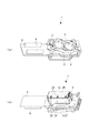
図1ないし図3に示すように、機能液滴吐出ヘッド1は、いわゆるピエゾ方式を採用した2連のインクジェットヘッド(インクジェット方式の液滴吐出ヘッド)であり、2連の接続針5を有する機能液導入部2と、機能液導入部2に連なる2連のヘッド基板3と、ヘッド基板3の下方に連なり機能液を吐出するヘッド本体4と、を備えている(図1(a)参照)。
As shown in FIG. 1 to FIG. 3, the functional liquid
機能液導入部2は、一対の接続針5を有しており、配管アダプタ(図示省略)を介して機能液供給ユニット53(図5参照)から機能液の供給を受けるようになっている。ヘッド基板3には、2連のコネクタ6,6が設けられており、各コネクタ6はフレキシブルフラットケーブル(図示省略)を介して吐出検査装置31の制御装置(制御手段)7(図4参照)に接続されている。そして、この制御装置7から出力された駆動波形が各コネクタ6を介して各圧電素子(ピエゾ素子)17に印加されることで、各吐出ノズル21から機能液が吐出される。
The functional
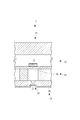
図2および図3に示すように、ヘッド本体4は、圧電素子17等で構成される2連のポンプ部11と、複数の吐出ノズル21が形成されたノズル面25を有するノズルプレート12と、を有している。各ポンプ部11は、吐出ノズル21の数に対応する圧電素子17を収容した機構部13と、機能液を貯留する貯留部14と、から構成されている。貯留部14は、圧電素子17の数に対応し、機能液を一時的に貯めるキャビティ15と、各キャビティ15に供給する機能液を溜めると共に上記の機能液導入部2に連通する共通室16と、から構成されている。機能液供給ユニット53から供給された機能液は、機能液導入部2を介して共通室16に流れ込む。そして、圧電素子17に電圧を印加して変形させることで、キャビティ15の体積変化を利用して共通室16からキャビティ15に機能液を導入すると共に、吐出ノズル21から機能液を吐出する。
As shown in FIG. 2 and FIG. 3, the
ノズルプレート12は、キャビティ15に貯留された機能液を吐出する吐出ノズル21が多数形成されている。多数の吐出ノズル21は、相互に平行、且つ半ピッチ位置ズレして列設された2列のノズル列22を構成しており、各ノズル列22は、等ピッチで並べた180個の吐出ノズル21で構成されている(図1(b)参照)。この場合、180個の吐出ノズル21のうち、両外端に位置する各10個の吐出ノズル21は、無効吐出ノズル23であり、実際の描画には使用しない。そのため、吐出検査では、無効吐出ノズル23(計20個)を除く有効吐出ノズル24(計160個)について吐出検査を実施する。
The
次に、図4を参照して機能液滴吐出ヘッド1の性能検査を行う検査システム30について説明する。図4に示すように、機能液滴吐出ヘッド1の検査システム30は、ガラス基板64と、機能液滴吐出ヘッド1をセットし、ガラス基板64上に機能液滴を検査吐出する吐出検査装置(吐出量特性検査装置)31と、ガラス基板64上に着弾した機能液滴(以下、着弾ドットD)の体積を測定する体積測定装置101と、を備えている。ユーザは、吐出検査装置31上にて、機能液滴吐出ヘッド1の各種吐出検査、測定(飛行曲がり検査や、駆動電圧測定、機能液滴の飛行速度測定等)を行うと共に、ガラス基板64に液滴を着弾(検査吐出)する。その後、ガラス基板64を体積測定装置101にセットして、ガラス基板64上の着弾ドットDの体積測定を行う。すなわち、本検査システム30は、吐出検査装置31上にて機能液滴吐出ヘッド1の各種吐出検査、測定を行うのに加えて、体積測定装置101と供して各着弾ドットDの体積測定を行う。これにより機能液滴吐出ヘッド1の性能を検査する。なお、請求項にいう吐出量測定手段は、吐出検査装置31および体積測定装置101により、構成されている。
Next, an
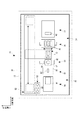
図5に示すように、吐出検査装置31は、機台32と、機台32上に載置され、機能液滴吐出ヘッド1の吐出性能を検査するヘッド検査装置33と、同様に機台32上に載置され、機能液滴吐出ヘッド1の機能維持および回復を行うメンテナンス装置34と、を有しておりチャンバ35内に収容されている。また、チャンバ35外には、制御装置7が備えられており、機能液滴吐出ヘッド1、ヘッド検査装置33およびメンテナンス装置34を統括的に制御する。吐出検査装置31は、機能液滴吐出ヘッド1を1つずつ検査すべく、メンテナンス装置34により機能液滴吐出ヘッド1の機能維持・回復を行いながら、ヘッド検査装置33により機能液を吐出して、機能液滴吐出ヘッド1の吐出性能を検査する。
As shown in FIG. 5, the
メンテナンス装置34は、吐出ノズル21における機能液の増粘や目詰まりによる吐出不良を解消する吸引装置36と、吸引装置36と並ぶように配設され、機能液滴吐出ヘッド1のノズル面25を払拭するワイピング装置37と、を有している。
The
吸引装置36は、機能液滴吐出ヘッド1のノズル面25に密接すると共に、R・G・B色に対応した3つのキャップ41と、吸引チューブ(図示省略)を介して3つのキャップ41に接続されたイジェクター(図示省略)と、を有している。吸引装置36は、各キャップ41を機能液滴吐出ヘッド1のノズル面25に密接させ、イジェクターにより吸引を行うことで、吐出ノズル21の目詰まり等による吐出不良を解消する。
The
ワイピング装置37は、ノズル面25に当接するワイピングシート42と、ワイピングシート42を繰り出すと共に巻き取るシート送り機構43(図6参照)と、を有している。ワイピング装置37は、ワイピングシート42を吐出ノズル21のノズル面25に押し当て、吐出ノズル21をXYテーブル52によりX軸方向に前後させることで、吸引処理後の機能液滴吐出ヘッド1のノズル面25を払拭する。
The wiping
ヘッド検査装置33は、1の機能液滴吐出ヘッド1が工具レスでセットされるヘッドホルダ51を有し、機能液滴吐出ヘッド1をX軸方向およびY軸方向に移動させるXYテーブル52と、供給チューブ(図示省略)を介して機能液滴吐出ヘッド1に機能液を供給する機能液供給ユニット53と、主に吐出された機能液の飛行曲がりや飛行速度を検査する飛行検査ユニット54と、吐出された機能液の吐出重量を測定する重量測定ユニット55と、ガラス基板64を載置するターゲットステージ56と、を備えている。機能液供給ユニット53は、XYテーブル52に付設され、飛行検査ユニット54、重量測定ユニット55およびターゲットステージ56は、XYテーブル52によりX軸方向に移動する機能液滴吐出ヘッド1の移動軌跡の下方に臨むよう、機台32上に並べて配設されている。
The
ヘッド検査装置33により機能液滴吐出ヘッド1の吐出性能を検査する場合は、機能液供給ユニット53から機能液滴吐出ヘッド1に機能液を供給しつつ、XYテーブル52により機能液滴吐出ヘッド1をX軸方向およびY軸方向に移動させて、飛行検査ユニット54、重量測定ユニット55およびターゲットステージ56にそれぞれ臨ませて、各検査を行う。
When the ejection performance of the functional liquid
機能液供給ユニット53は、R・G・B色の機能液をそれぞれ貯留する3つの機能液タンク61を有しており、各機能液タンク61は、機能液滴吐出ヘッド1より上方に配設され、セットした機能液滴吐出ヘッド1に応じて選択的に使用される。このため、機能液は、自然水頭により各機能液タンク61から各供給チューブを介して機能液滴吐出ヘッド1へ供給される。
The functional
飛行検査ユニット54は、パルス光源であるパルスレーザを有する照明部65と、照明部65に対向して配置され、パルスレーザによるパルス光を受光する顕微鏡カメラ66と、機能液滴吐出ヘッド1から吐出された機能液を受ける機能液受け部67と、を備えている。飛行速度の測定や飛行曲がりの検査を行う場合、照明部65と顕微鏡カメラ66を駆動させた状態で機能液を吐出する。吐出された機能液は、照明部65と顕微鏡カメラ66との間のパルスレーザを遮って、機能液受け部67に着弾する。そして、飛行検査ユニット54により高速度撮影された撮影結果に基づいて、飛行速度が計測されると共に、飛行曲がりがあるか否か、また吐出抜けがあるか否かを検査する。
The
重量測定ユニット55は、機能液滴吐出ヘッド1から吐出された機能液を受ける容器62と、容器62内の機能液の重量を測定する電子天秤63と、を備えている。重量測定ユニット55により機能液の吐出重量を測定する場合は、ノズル列22単位で数万発の機能液を吐出し、電子天秤63によりその機能液の吐出重量を測定する。
The
ターゲットステージ56は、体積測定用のガラス基板64を載置するものである。ここに載置したガラス基板64に対して、機能液滴吐出ヘッド1により検査吐出を実施して、複数の着弾ドットDをガラス基板64に形成する。そして、ガラス基板64は、着弾した液滴を自然乾燥させた後、体積測定装置101に移送され、着弾ドットDの個々の吐出量(体積)を測定する。
The target stage 56 is for mounting a
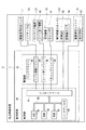
図6に示すように、制御装置7は、各種ドライバを有する駆動部81と、各部に接続され、吐出検査装置31全体の制御を行う制御部82と、を備えている。駆動部81には、機能液滴吐出ヘッド1を制御するヘッドドライバ83と、XYテーブル52を駆動させるヘッド移動ドライバ84と、ワイピング装置37のワイピングシート42をシート送りするシート送りドライバ85と、吸引装置36のキャップ41をノズル面25に対して昇降させるキャップドライバ86と、が備えられている。
As shown in FIG. 6, the control device 7 includes a
制御部82には、各手段を接続するためのインタフェース91と、一時的に記憶可能な記憶領域を有し、制御処理のための作業領域として使用されるRAM92と、各種記憶領域を有し、制御プログラムや制御データを記憶するROM93と、後述する運用前と運用後の吐出量データを含む各手段からの各種データ等を記憶すると共に、各種データを処理するためのプログラム等を記憶するハードディスク94と、ROM93やハードディスク94に記憶されたプログラム等に従い、各種データを演算処理するCPU95と、これらを互いに接続するバス96と、が備えられている。
The
そして、制御部82は、各部からの各種データを、インタフェース91を介して入力すると共に、ハードディスク94に記憶された(または、CD−ROMドライブ等により順次読み出される)プログラムに従ってCPU95に演算処理させ、その処理結果を、駆動部81(各種ドライバ)を介して各部に出力する。これにより、吐出検査装置31全体が制御され、各種処理が行われる。
The
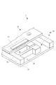
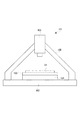
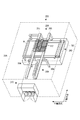
次に図7および図8を参照して、体積測定装置101について説明する。図7に示すように、体積測定装置101は、設置台102と、ガラス基板64を吸着固定するセットテーブル103と、設置台102上に配設され、セットテーブル103をXY方向で移動自在に支持する移動テーブル104と、セットテーブル103を跨ぐように設置台102上に配設されたフレーム105と、フレーム105によりセットテーブル103(ガラス基板64)の上方に配設された白色干渉計106と、を備えている。移動テーブル104により、ガラス基板64をXY方向で動かして、ガラス基板64上に着弾した着弾ドットDを白色干渉計106に1つずつ臨ませていき、全着弾ドットDを測定する。
Next, the
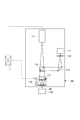
図8に示すように、白色干渉計106は、白色光を照射する光源となる白色LED111と、白色LED111の照射方向の下流側に設けられ、白色をフィルタリングする干渉フィルタ(バンドパスフィルタ)112と、干渉フィルタ112の下流側に設けられ、白色光を直角に反射する反射鏡113と、反射鏡113の下流側に設けられ、後述する干渉式対物レンズ(ミラウ型)114に向けて白色光を直角に反射される一方、撮像対象物(着弾ドットD)から反射した反射光を透過するビームスプリッタ115と、ビームスプリッタ115の下流側に設けられた干渉式対物レンズ114と、干渉式対物レンズ114をZ軸方向に微少振動させるピエゾZ軸テーブル116と、着弾ドットDから反射した反射光を干渉式対物レンズ114およびビームスプリッタ115を介して撮像する撮像カメラ(CCDカメラ)117と、を備えている。
As shown in FIG. 8, the
白色干渉計106は、対象物の表面形状を干渉縞として画像的に取得するものである。白色干渉計106による形状測定結果(撮像カメラ117による撮像結果)は、制御装置7に送信されて画像認識され、この画像認識に基づいて、各着弾ドットDの体積、さらに言えば、機能液滴吐出ヘッド1の各有効吐出ノズル24の吐出量が測定される。
The
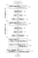
ここで、図9を参照して、本検査システム30における機能液滴吐出ヘッド1の吐出性能評価方法について説明する。この吐出性能評価方法では、運用前の機能液滴吐出ヘッド1における各有効吐出ノズル24の吐出量と、一定期間運用後の機能液滴吐出ヘッド1における各有効吐出ノズル24の吐出量とを測定し、その変化量に基づいて、機能液滴吐出ヘッド1の経時的変化を評価するものである。なお、運用前、運用後の機能液滴吐出ヘッド1の吐出量を測定する際、同時に機能液滴吐出ヘッド1の各種検査、測定を行っても良いが、ここでは、これらを省略して記載する。
Here, with reference to FIG. 9, the ejection performance evaluation method of the functional liquid
図9に示すように、まず、運用前の機能液滴吐出ヘッド1における各有効吐出ノズル24の吐出量を測定する第1吐出量測定工程(第1吐出量測定動作)を実行する(S1〜S4)。第1吐出量測定工程では、まず、ヘッドホルダ51に運用前の機能液滴吐出ヘッド1をセットする(S1)。運用前の機能液滴吐出ヘッド1をセットしたら、制御部82は、機能液滴吐出ヘッド1、および機能液滴吐出ヘッド1に接続した供給チューブ内に機能液を充填する機能液充填工程を実施する(S2)。すなわち、XYテーブル52により、機能液滴吐出ヘッド1を吸引装置36に臨ませて、吸引装置36により機能液滴吐出ヘッド1を吸引し、機能液を充填する。その後、機能液滴吐出ヘッド1をワイピング装置37に臨ませて、ワイピング装置37によりノズル面25を拭き取って機能液充填を終了する。
As shown in FIG. 9, first, a first discharge amount measuring step (first discharge amount measuring operation) for measuring the discharge amount of each
次に、制御部82は、XYテーブル52により、機能液滴吐出ヘッド1をターゲットステージ56に臨ませて、ターゲットステージ56上のガラス基板64に対し着弾ドット形成工程を実施する(S3)。着弾ドット形成工程では、機能液滴吐出ヘッド1の各有効吐出ノズル24を吐出駆動し、ガラス基板64上に複数の着弾ドットDを形成する。すなわち、ノズル列22ごとに吐出駆動を実施し、当該ノズル列22内の有効吐出ノズル24分の複数の着弾ドットDから成る着弾ドット列をそれぞれ形成する。なお、かかる際、全有効吐出ノズル24から測定吐出を同時に実施して、着弾ドット列を形成する構成としても良いが、複数(160個)の有効吐出ノズル24の測定吐出を間引いて行う複数種の測定吐出パターンを、各有効吐出ノズル24のショット数が同数に成るように切り替えながら、複数回の測定吐出を実施するようにしても良い。
Next, the
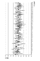
ガラス基板64に複数の着弾ドットDが形成されたら、ガラス基板64上の着弾ドットDが乾燥安定状態になるのを待って、ガラス基板64を体積測定装置101に移載(セット)し、体積測定工程を実施する(S4)。体積測定工程では、移動テーブル104により、ガラス基板64をXY方向に移動して、相対的に白色干渉計106を各着弾ドットD上に移動して、各着弾ドットDの体積を測定する。各着弾ドットDの体積は、各有効吐出ノズル24の吐出量と考えられるため、制御部82は、体積の測定結果に基づいて、縦軸を吐出量、横軸をノズル番号とするグラフ(図10参照)である吐出量データを取得する。なお、かかる際、図10に示すように、各有効吐出ノズル24の吐出量の値を、目標値(もしくは吐出量の平均値)に対する比で表した値(すなわち、目標値または平均値で正規化した値)とすることが好ましい。これにより、第1吐出量測定工程を終了する。
When a plurality of landing dots D are formed on the
次に、第1吐出量測定工程から一定期間運用後(もしくは一定期間経過後)、一定期間運用後の機能液滴吐出ヘッド1における各有効吐出ノズル24の吐出量を測定する第2吐出量測定工程(第2吐出量測定動作)を実行する(S5〜S8)。まず、ヘッドホルダ51に運用後の機能液滴吐出ヘッド1をセットする(S5)。その後、第1吐出量測定工程と同様に、機能液充填工程(S6)、着弾ドット形成工程(S7)および体積測定工程(S8)を実施して、第2吐出量測定工程を終了する。なお、ここにいう一定期間とは、年月日、時分等の時間を表すものであっても良いし、ショット数や描画処理回数等の動作回数を表すものであっても良い。
Next, after the first discharge amount measurement step has been operated for a certain period (or after a certain period has elapsed), the second discharge amount measurement is performed to measure the discharge amount of each
運用前および一定期間運用後の各吐出量を測定したら、各有効吐出ノズル24(計320個)において、運用後の吐出量から運用前の吐出量を減算して、その変化量を算出する変化量算出工程(減算算出工程および減算算出動作)を実行する(S9)。具体的には、運用前の機能液滴吐出ヘッド1における各有効吐出ノズル24の吐出量が(ノズル1、ノズル2、ノズル3、…)=(A1、A2、A3、…)であり、運用後の機能液滴吐出ヘッド1における各有効吐出ノズル24の吐出量が(ノズル1、ノズル2、ノズル3、…)=(B1、B2、B3…)である場合、運用後の各吐出量から運用前の各吐出量をそれぞれ減算して、各有効吐出ノズル24における変化量を算出する((ノズル1の変化量X1、ノズル2の変化量X2、ノズル3の変化量X3、…)=(B1−A1、B2−A2、B3−A3、…))。
Once each discharge amount before operation and after a certain period of operation is measured, each effective discharge nozzle 24 (a total of 320 nozzles) subtracts the discharge amount before operation from the discharge amount after operation, and calculates the change amount An amount calculation step (subtraction calculation step and subtraction calculation operation) is executed (S9). Specifically, the discharge amount of each
次に、算出した各変化量(X1、X2、X3、…)の標準偏差を算出する標準偏差算出工程(標準偏差算出動作)を実行する(S10)。すなわち、算出した複数の値の平均値(相加平均)を算出し(平均値X=1/320×(X1+X2+X3+…))、各値の偏差を求めると共に、その偏差の2乗平均を算出する(2乗平均の値σ2=1/320×{(X−X1)2+(X−X2)2+(X−X3)2+…})。最後に、その2乗平均の値の平方根を算出する(標準偏差σ=√(σ2))。このように、各値の標準偏差を算出する。 Next, a standard deviation calculating step (standard deviation calculating operation) for calculating the standard deviation of each calculated change amount (X1, X2, X3,...) Is executed (S10). That is, an average value (arithmetic average) of a plurality of calculated values is calculated (average value X = 1/320 × (X1 + X2 + X3 +...)), A deviation of each value is obtained, and a mean square of the deviation is calculated. (Square mean value σ 2 = 1/320 × {(X−X1) 2 + (X−X2) 2 + (X−X3) 2 +...}). Finally, the square root of the root mean square value is calculated (standard deviation σ = √ (σ 2 )). In this way, the standard deviation of each value is calculated.
次に、標準偏差に基づいて、機能液滴吐出ヘッド1を評価するヘッド評価工程(ヘッド評価動作)を実行する(S11)。具体的には、標準偏差の3倍(3σ)や標準偏差の6倍(6σ)を評価基準として、機能液滴吐出ヘッド1を評価する。例えば、標準偏差の3倍の値が、2.0以上の場合には、当該運用後の機能液滴吐出ヘッド1を「不良」とし、それ以外の場合には、その運用後の機能液滴吐出ヘッド1を「良」とする。なお、この2.0以上という値は、機能液滴吐出ヘッド1を用いて、フラットパネルディスプレイを作成した際、作成した当該フラットパネルディスプレイの品位が悪化し、許容範囲を超えてしまう値である。
Next, a head evaluation process (head evaluation operation) for evaluating the functional liquid
なお、本実施形態においては、機能液滴吐出ヘッド1を、良不良で評価したが、例えば、A、B、C…というように複数段階で機能液滴吐出ヘッド1を評価するものであっても良いし、標準偏差の3倍や6倍をそのまま評価結果とするものであっても良い。
In this embodiment, the functional liquid
以上のような構成によれば、上記標準偏差を評価基準とすることで、吐出量の変化量を基準として評価を実施することができるため、機能液滴吐出ヘッド1の経時的変化を正確に評価することができる。また、変化量を数値化して、評価基準とすることができるため、機能液滴吐出ヘッド1の経時的変化を容易に比較することができる。さらに、吐出量の変化量の指標と成る数値であると共に、変化量のバラツキ量の指標と成る数値を用いることで、変化量のみならず、変化量のバラツキをも基準として、評価を行うことができる。
According to the above configuration, since the evaluation can be performed based on the change amount of the discharge amount by using the standard deviation as an evaluation criterion, the change with time of the functional liquid
また、第1吐出量測定工程および第2吐出量測定工程を、着弾ドット形成工程および体積測定工程によって実行することで、複数の有効吐出ノズル24を同時に吐出駆動して、吐出量を測定することができるため、複数の有効吐出ノズル24を1ノズルずつ吐出駆動して、吐出量を測定するものと比較して、複数の有効吐出ノズル24の吐出量を容易に測定することができる。
Further, by performing the first discharge amount measurement step and the second discharge amount measurement step by the landing dot formation step and the volume measurement step, the plurality of
さらに、標準的に用いられる標準偏差の3倍(3σ)や標準偏差の6倍(6σ)の数値を、評価基準とすることで、機能液滴吐出ヘッド1の経時的変化が評価しやすくなる。
Furthermore, by using a numerical value that is three times the standard deviation (3σ) or six times the standard deviation (6σ) used as a standard for evaluation, it is easy to evaluate changes with time of the functional liquid
ここで図11を参照して、上記機能液滴吐出ヘッド1を用いた液滴吐出装置201について説明する。この液滴吐出装置201は、フラットパネルディスプレイの製造ラインに組み込まれており、例えば、特殊なインクや発光性の樹脂液である機能液を導入した機能液滴吐出ヘッド1を用い、液晶表示装置のカラーフィルタや有機EL装置の各画素となる発光素子等を形成するものである。
Here, with reference to FIG. 11, a
図11に示すように、液滴吐出装置201は、石定盤に支持されたX軸支持ベース202上に配設され、主走査方向となるX軸方向に延在してワークWをX軸方向に移動させるX軸移動テーブル203と、複数本の支柱204を介してX軸移動テーブル203を跨ぐように架け渡された1対のY軸支持ベース205上に配設され、主走査方向(X軸方向)に直交した副走査方向となるY軸方向に延在するY軸移動テーブル206と、Y軸移動テーブル206に移動自在に吊設され、複数個(12個)の機能液滴吐出ヘッド1が個々にキャリッジに搭載された10個のキャリッジユニット207と、複数個の機能液滴吐出ヘッド1の機能維持・機能回復処理を行うメンテナンス機構208と、から構成されている。さらに、液滴吐出装置201は、これらの装置を、温度および湿度が管理された雰囲気内に収容するチャンバ機構209と、チャンバ機構209を貫通して、機能液滴吐出ヘッド1に機能液を供給する機能液供給機構210と、液滴吐出装置201の各構成要素を制御する制御コンピュータ(図示省略)と、を備えている。
As shown in FIG. 11, the
液滴吐出装置201は、X軸移動テーブル203およびY軸移動テーブル206の駆動と同期して機能液滴吐出ヘッド1を吐出駆動させることにより、機能液供給機構210から供給された3色の機能液滴を吐出させ、ワークWに所定の描画パターンが描画される。
The
次に、上記評価方法における評価結果の使用方法について、いくつかの使用例を挙げて説明する。第1使用例では、評価結果を、当該一定期間運用後の機能液滴吐出ヘッド1を継続して使用するか否かの判定に用いる。すなわち、運用後の機能液滴吐出ヘッド1が「不良」と評価された場合には、その機能液滴吐出ヘッド1を破棄する(もしくは、機能液滴吐出ヘッド1のメンテナンスを実施する)。一方、運用後の機能液滴吐出ヘッド1が「良」と評価された場合には、その機能液滴吐出ヘッド1を継続して使用する。また、評価結果が、複数段階(A、B、C、…)もしくは標準偏差の3倍や6倍自身である場合には、その評価結果に合わせて、当該機能液滴吐出ヘッド1を使用頻度の少ない位置に配設することも考えられる。すなわち、評価が高いものは、使用頻度の多い位置(例えば、複数のキャリッジユニット207に亘る中央位置)に配設し、評価が低いものは、使用頻度が少ない位置(例えば、複数のキャリッジユニット207に亘る左右両端の位置)に配設する。さらに、評価結果(複数段階の評価や標準偏差の3倍、6倍)に基づいて、当該機能液滴吐出ヘッド1の寿命やメンテナンス時機を算出するものも考えられる。
Next, how to use the evaluation result in the above evaluation method will be described with some examples of use. In the first usage example, the evaluation result is used to determine whether or not to continue to use the functional liquid
第2使用例は、運用試験を実施し、その各運用期間での機能液滴吐出ヘッド1の評価結果に基づいて、当該機能液滴吐出ヘッド1と同種の製品の寿命を算出するものである。すなわち、運用試験の前に、第1吐出量測定工程を実施し、運用試験での各期間で、評価(第2吐出量測定工程、減算算出工程、標準偏差算出工程およびヘッド評価工程)を実行する。この各評価結果に基づいて、同種の製品の寿命を予測または決定する。このように、上記吐出性能評価方法の評価結果に基づいて、機能液滴吐出ヘッド1の寿命を予測、決定することにより、機能液滴吐出ヘッド1の寿命を精度良く決定することができる。
In the second usage example, an operation test is performed, and the lifetime of a product of the same type as the functional liquid
第3使用例は、運用試験による上記各運用期間での機能液滴吐出ヘッド1の評価結果に基づいて、当該機能液滴吐出ヘッド1と同種の製品のメンテナンス時機(メンテナンスを実施する時機)を決定するものである。このように、上記吐出性能評価方法の評価結果に基づいて、機能液滴吐出ヘッド1のメンテナンス時機を予測、決定することにより、メンテナンス時機を精度良く決定することができる。
In the third usage example, based on the evaluation result of the functional liquid
なお、本実施形態においては、ヘッド単体検査の吐出検査装置31上に、吐出評価装置を搭載する構成であったが、上記液滴吐出装置201上に、当該吐出評価装置を搭載する構成であっても良い。かかる場合、例えば、ワークW給除材時や描画処理の都度、上記評価を実施して、機能液滴吐出ヘッド1が適正であるか否かを判定することも考えられる。
In this embodiment, the discharge evaluation apparatus is mounted on the
また、本実施形態においては、本発明の吐出性能評価方法を、機能液を吐出する機能液滴吐出ヘッド1に適用したが、本発明の吐出性能評価方法を、インクジェットプリンター等に用い、インクを吐出するインクジェットヘッドに適用しても良い。
In this embodiment, the ejection performance evaluation method of the present invention is applied to the functional liquid
さらに、本実施形態においては、各変化量の標準偏差に基づいて、評価を実施しているが、各変化量の2乗平均平方根(RMS:Root Mean Square)に基づいて、評価を実施する構成であっても良い。 Further, in the present embodiment, the evaluation is performed based on the standard deviation of each change amount, but the evaluation is performed based on the root mean square (RMS) of each change amount. It may be.
1:機能液滴吐出ヘッド、 7:制御装置、 21:吐出ノズル、 30:検査システム、 31:吐出検査装置、 101:体積測定装置、 D:着弾ドット 1: functional droplet discharge head, 7: control device, 21: discharge nozzle, 30: inspection system, 31: discharge inspection device, 101: volume measuring device, D: landing dot
Claims (6)
前記複数の吐出ノズルの吐出量を測定する第1吐出量測定工程と、
前記第1吐出量測定工程から一定期間経過後、前記複数の吐出ノズルの吐出量を測定する第2吐出量測定工程と、
前記各吐出ノズルにおいて、前記第2吐出量測定工程で測定した吐出量から、前記第1吐出量測定工程で測定した吐出量を減算した値を、それぞれ算出する減算算出工程と、
算出した前記各値の標準偏差を算出する標準偏差算出工程と、
前記標準偏差に基づいて、前記液滴吐出ヘッドの経時的変化を評価するヘッド評価工程と、を備えたことを特徴とする液滴吐出ヘッドの吐出性能評価方法。 A method for evaluating the discharge performance of a droplet discharge head for evaluating a change with time of the discharge performance of a droplet discharge head having a plurality of discharge nozzles,
A first discharge amount measuring step for measuring discharge amounts of the plurality of discharge nozzles;
A second discharge amount measuring step of measuring discharge amounts of the plurality of discharge nozzles after a lapse of a certain period from the first discharge amount measuring step;
In each discharge nozzle, a subtraction calculation step for calculating a value obtained by subtracting the discharge amount measured in the first discharge amount measurement step from the discharge amount measured in the second discharge amount measurement step;
A standard deviation calculating step of calculating a standard deviation of each calculated value;
And a head evaluation step of evaluating a change with time of the droplet discharge head based on the standard deviation.
前記複数の吐出ノズルから測定吐出を実施して、前記複数の吐出ノズル分の複数の着弾ドットを形成する着弾ドット形成工程と、
形成した前記複数の着弾ドットの体積をそれぞれ測定することで、前記複数の吐出ノズルの吐出量を測定する体積測定工程と、をそれぞれ備えたことを特徴とする請求項1に記載の液滴吐出ヘッドの吐出性能評価方法。 The first discharge amount measuring step and the second discharge amount measuring step include:
A landing dot forming step of performing measurement discharge from the plurality of discharge nozzles to form a plurality of landing dots for the plurality of discharge nozzles;
2. The liquid droplet ejection according to claim 1, further comprising: a volume measurement step of measuring a volume of the plurality of ejection nozzles to measure a volume of the plurality of ejection nozzles. Evaluation method of head ejection performance.
前記複数の吐出ノズルの吐出量を測定する吐出量測定手段と、
前記液滴吐出ヘッドおよび前記吐出量測定手段を制御する制御手段と、を備え、
前記制御手段は、
前記吐出量測定手段により、前記複数の吐出ノズルの吐出量を測定する第1吐出量測定動作と、
前記吐出量測定手段により、前記第1吐出量測定動作から一定期間経過後、前記複数の吐出ノズルの吐出量を測定する第2吐出量測定動作と、
前記各吐出ノズルにおいて、前記第2吐出量測定動作で測定した吐出量から、前記第1吐出量測定動作で測定した吐出量を減算した値を、それぞれ算出する減算算出動作と、
算出した前記各値の標準偏差を算出する標準偏差算出動作と、
前記標準偏差に基づいて、前記液滴吐出ヘッドの経時的変化を評価するヘッド評価動作と、を実行することを特徴とする液滴吐出ヘッドの吐出性能評価装置。 An apparatus for evaluating the discharge performance of a droplet discharge head for evaluating a change with time of the discharge performance of a droplet discharge head having a plurality of discharge nozzles,
A discharge amount measuring means for measuring a discharge amount of the plurality of discharge nozzles;
Control means for controlling the droplet discharge head and the discharge amount measuring means,
The control means includes
A first discharge amount measuring operation for measuring the discharge amounts of the plurality of discharge nozzles by the discharge amount measuring means;
A second discharge amount measuring operation for measuring the discharge amount of the plurality of discharge nozzles after a predetermined period of time has elapsed from the first discharge amount measuring operation by the discharge amount measuring means;
A subtraction calculation operation for calculating a value obtained by subtracting the discharge amount measured in the first discharge amount measurement operation from the discharge amount measured in the second discharge amount measurement operation in each of the discharge nozzles;
A standard deviation calculating operation for calculating a standard deviation of each calculated value;
And a head evaluation operation for evaluating a change with time of the droplet discharge head based on the standard deviation.
Priority Applications (1)
| Application Number | Priority Date | Filing Date | Title |
|---|---|---|---|
| JP2008323634A JP2010142744A (en) | 2008-12-19 | 2008-12-19 | Method of evaluating discharge performance of droplet discharge head, method of deciding maintenance timing of droplet discharge head, method of predicting and deciding service life of droplet discharge head and apparatus for evaluating discharge perormance of droplet discharge head |
Applications Claiming Priority (1)
| Application Number | Priority Date | Filing Date | Title |
|---|---|---|---|
| JP2008323634A JP2010142744A (en) | 2008-12-19 | 2008-12-19 | Method of evaluating discharge performance of droplet discharge head, method of deciding maintenance timing of droplet discharge head, method of predicting and deciding service life of droplet discharge head and apparatus for evaluating discharge perormance of droplet discharge head |
Publications (1)
| Publication Number | Publication Date |
|---|---|
| JP2010142744A true JP2010142744A (en) | 2010-07-01 |
Family
ID=42563730
Family Applications (1)
| Application Number | Title | Priority Date | Filing Date |
|---|---|---|---|
| JP2008323634A Withdrawn JP2010142744A (en) | 2008-12-19 | 2008-12-19 | Method of evaluating discharge performance of droplet discharge head, method of deciding maintenance timing of droplet discharge head, method of predicting and deciding service life of droplet discharge head and apparatus for evaluating discharge perormance of droplet discharge head |
Country Status (1)
| Country | Link |
|---|---|
| JP (1) | JP2010142744A (en) |
Cited By (4)
| Publication number | Priority date | Publication date | Assignee | Title |
|---|---|---|---|---|
| CN107531056A (en) * | 2015-02-12 | 2018-01-02 | 夸德泰克公司 | The system and method used for the ink monitored in print system |
| CN115796051A (en) * | 2022-12-26 | 2023-03-14 | 富联裕展科技(深圳)有限公司 | A method and device for predicting the life of a dispensing needle |
| JP2023069853A (en) * | 2021-11-08 | 2023-05-18 | 東京エレクトロン株式会社 | Droplet ejection device, parameter calculation method, substrate processing system |
| KR20230154613A (en) * | 2022-05-02 | 2023-11-09 | 세메스 주식회사 | Apparatus and method for evaluating life time og head |
-
2008
- 2008-12-19 JP JP2008323634A patent/JP2010142744A/en not_active Withdrawn
Cited By (6)
| Publication number | Priority date | Publication date | Assignee | Title |
|---|---|---|---|---|
| CN107531056A (en) * | 2015-02-12 | 2018-01-02 | 夸德泰克公司 | The system and method used for the ink monitored in print system |
| JP2023069853A (en) * | 2021-11-08 | 2023-05-18 | 東京エレクトロン株式会社 | Droplet ejection device, parameter calculation method, substrate processing system |
| JP7744101B2 (en) | 2021-11-08 | 2025-09-25 | 東京エレクトロン株式会社 | Droplet ejection device, parameter calculation method, and substrate processing system |
| KR20230154613A (en) * | 2022-05-02 | 2023-11-09 | 세메스 주식회사 | Apparatus and method for evaluating life time og head |
| KR102735506B1 (en) | 2022-05-02 | 2024-11-29 | 세메스 주식회사 | Apparatus and method for evaluating life time og head |
| CN115796051A (en) * | 2022-12-26 | 2023-03-14 | 富联裕展科技(深圳)有限公司 | A method and device for predicting the life of a dispensing needle |
Similar Documents
| Publication | Publication Date | Title |
|---|---|---|
| JP2009022915A (en) | Droplet ejection method and droplet ejection apparatus | |
| JP2007256449A (en) | Droplet ejecting inspection apparatus, droplet ejecting apparatus, and manufacturing method of application body | |
| JP2010142744A (en) | Method of evaluating discharge performance of droplet discharge head, method of deciding maintenance timing of droplet discharge head, method of predicting and deciding service life of droplet discharge head and apparatus for evaluating discharge perormance of droplet discharge head | |
| JP2006284406A (en) | Dot shift detection method, dot shift detection program, reference straight line acquisition method, dot shift detection device, and droplet discharge device | |
| KR102795821B1 (en) | Substrate inspecting unit and substrate treating apparatus including the same | |
| KR102923175B1 (en) | Nozzle inspecting unit and substrate treating apparatus including the same | |
| JP2010120237A (en) | Delivery examination method for functional liquid droplet discharge head, and delivery examination device for the same | |
| KR102855180B1 (en) | Substrate treating apparatus | |
| JP2006281116A (en) | Dot quality detection method, dot quality detection device, and droplet discharge device | |
| JP5146294B2 (en) | Droplet discharge head discharge amount measurement method, drive voltage determination method, droplet discharge device, and droplet discharge head discharge amount measurement device | |
| JP5169511B2 (en) | Head inspection apparatus, head inspection method, and droplet discharge apparatus | |
| JP4529755B2 (en) | Dot diameter correction coefficient acquisition method, dot diameter measurement method, dot diameter abnormality detection method, dot diameter measurement device, dot diameter abnormality detection device, and droplet discharge device | |
| JP2009045547A (en) | Discharge weight measuring method, droplet discharge head maintenance method, droplet discharge apparatus, and droplet discharge method | |
| KR102882047B1 (en) | Droplet analysing unit and substrate treating apparatus including the same | |
| JP2008298690A (en) | Landing dot volume measuring method and volume measuring system | |
| JP2010119989A (en) | Method of measuring discharge weight of droplet discharge head, method of deciding driving voltage of droplet discharge head, droplet discharge apparatus, and apparatus of measuring discharge weight of droplet discharge head | |
| JP2010119985A (en) | Discharge quantity characteristic examining method of droplet discharge head, driving voltage determining method of droplet discharge head, droplet discharge device and discharge quantity characteristic examining apparatus for droplet discharge head | |
| JP2011101870A (en) | Method for obtaining ejection amount from droplet ejection head, method for determining appropriate voltage, and droplet ejection device | |
| JP2010139294A (en) | Method for measuring volume of impact dot | |
| KR102888457B1 (en) | Substrate treating apparatus and method thereof | |
| JP2009248469A (en) | Discharging performance examining method of functional liquid droplet discharge head and discharging performance examining device of functional liquid droplet discharge head | |
| JP2008302637A (en) | Method for determining drive voltage of droplet discharge head | |
| JP2010137125A (en) | Method of measuring discharge amount from droplet discharge head, method of deciding driving voltage, droplet discharge device, and apparatus for measuring discharge amount for droplet discharge head | |
| KR102779998B1 (en) | Droplet analysing unit and substrate treating apparatus including the same | |
| JP2011110443A (en) | Method for setting drive voltage of liquid droplet discharge head, and liquid droplet discharge head |
Legal Events
| Date | Code | Title | Description |
|---|---|---|---|
| A621 | Written request for application examination |
Effective date: 20111205 Free format text: JAPANESE INTERMEDIATE CODE: A621 |
|
| A761 | Written withdrawal of application |
Effective date: 20120302 Free format text: JAPANESE INTERMEDIATE CODE: A761 |