JP2010142544A - Storage furniture - Google Patents
Storage furnitureInfo
- Publication number
- JP2010142544A JP2010142544A JP2008325178A JP2008325178A JP2010142544A JP 2010142544 A JP2010142544 A JP 2010142544A JP 2008325178 A JP2008325178 A JP 2008325178A JP 2008325178 A JP2008325178 A JP 2008325178A JP 2010142544 A JP2010142544 A JP 2010142544A
- Authority
- JP
- Japan
- Prior art keywords
- storage
- front plate
- unit
- storage unit
- joint
- Prior art date
- Legal status (The legal status is an assumption and is not a legal conclusion. Google has not performed a legal analysis and makes no representation as to the accuracy of the status listed.)
- Granted
Links
Images


Landscapes
- Drawers Of Furniture (AREA)
Abstract
【課題】簡易な構成により美観性を向上し得る収納家具を提供する。
【解決手段】前方に開口した第一の収納庫11及びその開口を開閉自在に閉塞する第一の前板14を有する第一の収納ユニット10と、前方に開口した第二の収納庫21及びその開口を開閉自在に閉塞する第二の前板24を有する第二の収納ユニット20とを、隣接させて組み合わせることにより構成された収納家具1であって、前記第二の収納ユニットは、閉状態における前記第二の前板が奥方に少許押し込まれることによって当該第二の前板を開放させるプッシュオープン機構26を備え、前記第二の収納ユニットにおける前記第二の収納庫の前面21aが前記第一の収納ユニットにおける第一の収納庫の前面11aよりも少許奥方に位置して、これら両ユニットの接合目地jに段差部gが形成されており、前記段差部には、前記第一の収納庫の前面から前記第二の収納庫の前面にかけて沿面を形成する形状とされた目地部材27が設けられている。
【選択図】図1A storage furniture capable of improving aesthetics with a simple configuration.
A first storage unit 10 having a first storage 11 opened forward and a first front plate 14 closing the opening so as to be openable and closable; a second storage 21 opened forward; A storage furniture 1 configured by combining a second storage unit 20 having a second front plate 24 that closes the opening so as to be freely opened and closed, wherein the second storage unit is closed. The second front plate in the state is provided with a push-open mechanism 26 that opens the second front plate by being pushed slightly into the back, and the front surface 21a of the second storage in the second storage unit is A stepped portion g is formed in a joint joint j between these two units, located at a depth less than the front surface 11a of the first storage unit in the first storage unit. Joint member 27 which is shaped to form a creepage from the front surface of the accommodated chamber toward the front of the second storage box is provided.
[Selection] Figure 1
Description
本発明は、前方に開口した第一の収納庫及びその開口を開閉自在に閉塞する第一の前板を有する第一の収納ユニットと、前方に開口した第二の収納庫及びその開口を開閉自在に閉塞する第二の前板を有する第二の収納ユニットとを、隣接させて組み合わせることにより構成された収納家具に関する。 The present invention relates to a first storage unit having a first storage box opened forward and a first front plate closing the opening so as to be opened and closed, a second storage box opened forward, and opening and closing the opening. The present invention relates to storage furniture configured by combining a second storage unit having a second front plate that is freely closed and adjacent to each other.
上記のような収納家具(キャビネット)としては、住居等の建物のリビングやダイニングスペース等の居室空間、或いは台所や洗面化粧台、玄関等に設置され、その設置スペースや趣向に応じて、種々のユニット化(モジュール化)された収納家具を適宜、組み合わせて構成するものが知られている。
上記のようにユニット化された各収納家具は、大略的に、前方に開口した収納庫と、該収納庫の開口を開閉自在に閉塞する前板とを備えており、例えば、該収納庫に引出しを出し入れ(引出し)自在に収納し、該引出しを収納スペースとしたものや、該収納庫自体を収納スペースとし、その開口を閉塞する開き扉を備えた開き収納などがある。
上記のような収納庫の開口を開閉自在に閉塞する前板(引出しの場合は、該引出しの前板、開き収納の場合は、開き扉等)を備えた収納家具としては、閉状態における該前板が奥方に少許押し込まれることによって当該前板を開放させるプッシュオープン機構を備えたもの(いわゆるプッシュオープン式収納家具)が知られている。
例えば、下記特許文献1では、シンクキャビネットとコンロキャビネットとの間に組み込み設置され、プッシュオープン引出しを備えたベースキャビネットが提案されている。
Each storage furniture unitized as described above generally includes a storage box that opens forward, and a front plate that opens and closes the opening of the storage box. There are drawers that can be freely put in and out (drawn), and the drawer is used as a storage space, and there is an open storage that includes an opening door that closes the opening.
The storage furniture provided with a front plate (opener in the case of drawer, open door in the case of open storage, etc.) that closes the opening of the storage as described above is closed. 2. Description of the Related Art There is known a push-open mechanism (so-called push-open type storage furniture) that opens a front plate when the front plate is pushed slightly into the back.
For example,
ところで、上述のようなプッシュオープン式収納家具では、前板を少許押し込むことによって、プッシュオープン機構のロック手段等の解除がなされ、該前板が直接的或いは間接的に付勢手段等によって付勢されて、手前側(開放側)に向けて移動する構成とされている。
このように、プッシュオープン式収納家具では、前板を少許押し込む必要があるため、前板の裏面と、その収納庫の前面(開口縁端面)との間に、上記押し込みのためのスペースを設ける必要がある。
一方、このようなプッシュオープン機構を備えていない収納家具(以下、非プッシュオープン式収納家具と言う。)は、前板の裏面と、収納庫の前面との間に、上記のような押し込みのためのスペースを設ける必要がなく、該前板が閉塞された状態では、これらの間に隙間等が形成されないようにすることが好ましい。
By the way, in the push-open type storage furniture as described above, by pushing the front plate a little, the lock means of the push-open mechanism is released, and the front plate is directly or indirectly biased by the biasing means or the like. Thus, it is configured to move toward the front side (open side).
As described above, in the push-open type storage furniture, it is necessary to push the front plate a little, so a space for pushing in is provided between the back surface of the front plate and the front surface (opening edge end surface) of the storage case. There is a need.
On the other hand, storage furniture that does not have such a push-open mechanism (hereinafter referred to as non-push-open storage furniture) is pushed in between the back of the front plate and the front of the storage. There is no need to provide a space for this, and when the front plate is closed, it is preferable not to form a gap or the like between them.
上記のようなプッシュオープン式収納家具と、非プッシュオープン式収納家具とを、例えば、幅方向に並べて隣接させたり、高さ方向に積重ねて隣接させたりして、組み合わせることにより、組み合わせ家具を構成するような場合においては、以下のような問題があった。
すなわち、上記各収納家具の収納庫の各前面を揃えて設置するような場合においては、上記のようにプッシュオープン式収納家具は、上記押し込みのためのスペースを確保する必要があるため、当該プッシュオープン式収納家具の前板が、非プッシュオープン式収納家具の前板よりも僅かに手前に配置されることとなり、見栄えが悪いという問題があった。つまり、プッシュオープン式収納家具の前板と、非プッシュオープン式収納家具の前板との間に、段差が形成されてしまい、意匠性の観点から改善が望まれていた。
Combining the above-mentioned push-open storage furniture and non-push-open storage furniture, for example, by arranging them side by side in the width direction or by stacking them adjacent in the height direction In such a case, there were the following problems.
In other words, in the case where the fronts of the storage cabinets of the storage furniture are installed in a line, the push-open storage furniture needs to secure a space for the push-in as described above. The front plate of the open-type storage furniture is arranged slightly in front of the front plate of the non-push-open storage furniture, and there is a problem that the appearance is poor. That is, a step is formed between the front plate of the push-open storage furniture and the front plate of the non-push-open storage furniture, and improvement has been desired from the viewpoint of design.
本発明は、上記実情に鑑みなされたものであり、簡易な構成により美観性を向上し得る収納家具を提供することを目的としている。 This invention is made | formed in view of the said situation, and it aims at providing the storage furniture which can improve aesthetics by simple structure.
前記目的を達成するために、本発明に係る収納家具は、前方に開口した第一の収納庫及びその開口を開閉自在に閉塞する第一の前板を有する第一の収納ユニットと、前方に開口した第二の収納庫及びその開口を開閉自在に閉塞する第二の前板を有する第二の収納ユニットとを、隣接させて組み合わせることにより構成された収納家具であって、前記第二の収納ユニットは、閉状態における前記第二の前板が奥方に少許押し込まれることによって当該第二の前板の開放動作を補助するためのプッシュオープン機構を備え、前記第二の収納ユニットにおける前記第二の収納庫の前面は、前記第一の収納ユニットにおける第一の収納庫の前面よりも少許奥方に位置して、これら両ユニットの接合目地に段差部が形成されており、前記段差部には、前記第一の収納庫の前面から前記第二の収納庫の前面にかけて沿面を形成する形状とされた目地部材が設けられていることを特徴とする。 In order to achieve the above object, a storage furniture according to the present invention includes a first storage unit having a first storage box opened forward and a first front plate closing the opening so as to be openable and closable. Storage furniture constructed by combining a second storage unit having an opening and a second storage unit having a second front plate that closes the opening so as to be freely opened and closed. The storage unit includes a push-open mechanism for assisting an opening operation of the second front plate by pushing the second front plate in the closed state slightly into the back, and the second storage unit in the second storage unit The front surface of the second storage is located a little deeper than the front surface of the first storage in the first storage unit, and a step portion is formed at the joint joint between these two units. Before Characterized in that a first said second from the front of the storage box of the storing box joint member which is shaped to form a creepage toward the front of is provided.
本発明に係る前記収納家具においては、前記第一の収納ユニットにおける第一の前板を、第二の前板側の端面が前記接合目地よりも前記第二の前板側に位置するように形成してもよい。
本発明に係る前記いずれかの収納家具においては、前記第一の前板と、前記第二の前板とを、略同厚さとしてもよい。
本発明に係る前記いずれかの収納家具においては、前記目地部材を、前記第二の収納庫における前記接合目地側の前面に添設するようにしてもよい。
In the storage furniture according to the present invention, the first front plate in the first storage unit is arranged such that the end surface on the second front plate side is located on the second front plate side with respect to the joint joint. It may be formed.
In any one of the storage furniture according to the present invention, the first front plate and the second front plate may have substantially the same thickness.
In any one of the storage furniture according to the present invention, the joint member may be attached to the front surface on the joint joint side in the second storage.
本発明に係る前記収納家具は、前記第二の収納ユニットにおける前記第二の収納庫の前面が前記第一の収納ユニットにおける第一の収納庫の前面よりも少許奥方に位置しているので、上記プッシュオープン機構を備えた第二の収納ユニットにおける第二の収納庫の前面と、第二の前板の裏面との間に、当該前板を押し込むためのスペースを確保しながらも、第一の収納ユニットの前板と、第二の収納ユニットの前板とを、それぞれが閉塞された状態において、略面一となるように配置できる。換言すれば、上記プッシュオープン機構を備えた第二の収納ユニットにおける第二の前板の押し込みスペースを、第二の収納庫の前面を、第一の収納庫の前面よりも少許奥方に配置することで確保することができるので、例えば、当該押し込みスペースを確保するために、第二の収納ユニットにおける第二の前板を、第一の収納ユニットにおける第一の前板よりも手前側に位置させるような必要がない。従って、第一の収納ユニットの前板と、第二の収納ユニットの前板とを、それぞれが閉塞された状態において、略面一となるように配置でき、美観性に優れたものとなる。
また、前記第二の収納ユニットにおける前記第二の収納庫の前面が前記第一の収納ユニットにおける第一の収納庫の前面よりも少許奥方に位置して、これら両ユニットの接合目地に形成された段差部には、前記第一の収納庫の前面から前記第二の収納庫の前面にかけて沿面を形成する形状とされた目地部材が設けられているので、例えば、いずれかの前板を開放させた際にも、当該段差部が上記目地部材によって緩和されるので、該段差部が目立たず、美観性に優れたものとなる。
In the storage furniture according to the present invention, since the front surface of the second storage unit in the second storage unit is located at a depth less than the front surface of the first storage unit in the first storage unit, While securing a space for pushing the front plate between the front surface of the second storage case and the back surface of the second front plate in the second storage unit having the push-open mechanism, The front plate of the storage unit and the front plate of the second storage unit can be arranged so as to be substantially flush with each other in the closed state. In other words, the pushing space of the second front plate in the second storage unit provided with the push-open mechanism is arranged such that the front surface of the second storage is less allowed than the front surface of the first storage. For example, in order to secure the pushing space, the second front plate in the second storage unit is positioned closer to the front side than the first front plate in the first storage unit. There is no need to let them. Therefore, the front plate of the first storage unit and the front plate of the second storage unit can be arranged so as to be substantially flush with each other in the closed state, and the aesthetic appearance is excellent.
In addition, the front surface of the second storage in the second storage unit is located at a depth less than the front surface of the first storage in the first storage unit, and is formed at a joint joint between these two units. Since the step portion is provided with a joint member that forms a creeping surface from the front surface of the first storage to the front surface of the second storage, for example, one of the front plates is opened. In this case, since the stepped portion is relaxed by the joint member, the stepped portion is not conspicuous and has excellent aesthetics.
本発明に係る前記収納家具において、前記第一の収納ユニットにおける第一の前板を、第二の前板側の端面が前記接合目地よりも前記第二の前板側に位置するように形成すれば、上記第一の収納ユニットにおける前板を閉塞させた状態では、該第一の前板によって、上記目地部材を、より目立たせないようにすることができる。すなわち、上記段差部に設けられた目地部材と上記第一の収納庫との接合部位が、手前側から見た際に閉塞状態とされた第一の前板によって隠蔽され、該目地部材の少なくとも一部を上記第一の前板によって隠蔽することができる。 In the storage furniture according to the present invention, the first front plate in the first storage unit is formed such that the end surface on the second front plate side is located on the second front plate side with respect to the joint joint. Then, in a state where the front plate in the first storage unit is closed, the joint member can be made less conspicuous by the first front plate. That is, the joint portion between the joint member provided in the step portion and the first storage is concealed by the first front plate that is closed when viewed from the front side, and at least the joint member A part can be concealed by the first front plate.
本発明に係る前記いずれかの収納家具において、前記第一の前板と、前記第二の前板とを、略同厚さとすれば、第一の前板と、第二の前板とを同一の板材料から切り出して製造することができるので、部材コストを低減できるとともに、同一の質感を現出でき、美観性に優れたものとなる。すなわち、上述のように、押し込みスペースを確保するとともに、隣接する両ユニットの前板を、それぞれの前面が略面一となるように配置させる場合には、プッシュオープン機構を備えたユニットの前板の厚みを、他方のユニットにおける前板の厚みよりも薄く形成することで、該押し込みスペースを確保することも考えられる。しかしながら、このようなものでは、別の板材から各前板を切り出して製造する必要があり、部材コストが高くなるとともに、開放させた際に、前板の質感に差異が生じてしまい、見栄えが悪くなる。
一方、上記構成とされた本発明によれば、部材コストを低減できるとともに、同一の質感を現出でき、美観性に優れたものとなる。
In any one of the storage furniture according to the present invention, if the first front plate and the second front plate have substantially the same thickness, the first front plate and the second front plate are provided. Since it can cut out and manufacture from the same board | plate material, while being able to reduce member cost, the same texture can be revealed and it becomes what was excellent in aesthetics. That is, as described above, when securing the push-in space and arranging the front plates of both adjacent units so that the front surfaces thereof are substantially flush with each other, the front plate of the unit provided with the push-open mechanism It is also conceivable to secure the pushing-in space by forming the thickness of the lower than the thickness of the front plate in the other unit. However, in such a case, it is necessary to cut and manufacture each front plate from another plate material, which increases the cost of the member and causes a difference in the texture of the front plate when opened, which makes it look good. Deteriorate.
On the other hand, according to the present invention configured as described above, the member cost can be reduced, the same texture can be revealed, and the appearance is excellent.
本発明に係る前記いずれかの収納家具において、前記目地部材を、前記第二の収納庫における前記接合目地側の前面に添設するようにすれば、上記第一の収納ユニットと上記第二の収納ユニットとを隣接させて組み付ける際に、該目地部材の前端縁部を、上記第一の収納ユニットにおける第一の収納庫の前縁部に位置合わせすることで、容易に組み付けることができ、施工性を向上させることができる。 In any one of the storage furniture according to the present invention, when the joint member is attached to the front surface on the joint joint side in the second storage, the first storage unit and the second storage unit are provided. When assembling the storage unit adjacent to each other, the front end edge of the joint member can be easily assembled by aligning with the front edge of the first storage in the first storage unit, Workability can be improved.
以下に本発明の最良の実施の形態について、図面に基づいて説明する。
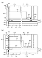
図1は、本実施形態に係る収納家具を模式的に示す概略側面図、図2(a)、(b)は、いずれも同収納家具における前板の開閉動作を説明するための説明図であり、(a)は、前板を押し込んだ状態における一部破断概略側面図、(b)は、開放状態における一部破断概略側面図、図3は、同収納家具の組み付け工程を説明するための分解概略側面図である。図4は、同収納家具を用いたシステムキッチンのフロアユニットの一例を模式的に示す概略斜視図である。
尚、以下の実施形態で示す前方及び奥方は、収納家具(キャビネット)に対面した使用者を基準として示している。また、図1〜図3では、後記する加熱調理器ユニットの図示を省略し、図2では、引出しレール及び図2における紙面手前側の側板の図示を省略し、図4では、水栓金具等の図示を省略している。
The best mode for carrying out the present invention will be described below with reference to the drawings.
FIG. 1 is a schematic side view schematically showing the storage furniture according to the present embodiment, and FIGS. 2A and 2B are explanatory diagrams for explaining the opening / closing operation of the front plate in the storage furniture. Yes, (a) is a partially broken schematic side view in a state where the front plate is pushed in, (b) is a partially broken schematic side view in an opened state, and FIG. 3 is for explaining the assembly process of the storage furniture. FIG. FIG. 4 is a schematic perspective view schematically showing an example of a floor unit of a system kitchen using the storage furniture.
In addition, the front and back shown by the following embodiment are shown on the basis of the user who faced storage furniture (cabinet). 1 to 3, the illustration of a heating cooker unit to be described later is omitted, the drawing rail and the side plate on the front side in FIG. 2 are omitted in FIG. 2, and a faucet fitting and the like are shown in FIG. 4. Is omitted.
本実施形態に係る収納家具1は、図4に示すように、いわゆるシステムキッチンにおいて床側に設置されるフロアユニットAの一部に組み込まれ、該フロアユニットAの一部を構成するキッチン用キャビネット1に適用した例を図示しており、より特定的に説明すれば、加熱調理器ユニット6等を備えた調理器キャビネット1に適用した例を図示している。
上記フロアユニットAは、図4に示すように、大略的に、上記調理器キャビネット1と、シンク2aを配したシンクキャビネット2と、これら調理器キャビネット1及びシンクユニット2の間に配された引出しキャビネット3と、これら各キャビネット1,2,3の上部に配されたカウンター(ワークトップ)4と、上記各キャビネット1,2,3で構成されたキャビネットの集合体の左右サイドを覆い隠すためのサイドパネル(エンドパネル)5とを備えている。
As shown in FIG. 4, the
As shown in FIG. 4, the floor unit A generally includes the
上記調理器キャビネット1は、図4に示すように、大略的に、上記カウンター4に開設された開口に嵌め込まれたコンロ部6aやグリル部6b、各種操作パネル等を有した加熱調理器ユニット6と、該加熱調理器ユニット6の下方に配置され、該加熱調理器ユニット6が載置される調理器下ユニット(第一の収納ユニット)10と、該調理器下ユニット10の上部に載置されるとともに、上記加熱調理器ユニット6の側方に配された小引出しユニット(第二の収納ユニット)20とを備えている。
As shown in FIG. 4, the
上記調理器下ユニット10は、図1に示すように、前方に開口した方形箱状の調理器下収納庫11と、該調理器下収納庫11に出し入れ自在に収納される中段引出し13及び下段引出し17とを備えている。
本実施形態では、この調理器下収納庫11は、二段の引出し13,17を出し入れ自在に収納する収納庫として機能し、その開口は、両引出し間に設けられた棚板(仕切り板、不図示)によって仕切られており、二つの開口が設けられた態様となる。
また、これら各引出し13,17は、上記調理器下収納庫11の両側板11c,11cの内側面に設けられたスライドレール12,16によってそれぞれ出し入れ自在に支持されており、これら各引出し13,17は、プッシュオープン機構を備えておらず、手動で出し入れがなされる構成とされている。すなわち、該調理器下ユニット10は、非プッシュオープン式収納ユニットとされている。
As shown in FIG. 1, the cooker lower unit 10 includes a rectangular box-shaped cooker
In the present embodiment, the cooking appliance
The
上記各引出し13,17の各前板14,18によって、上記調理器下収納庫11の両開口が開閉自在に閉塞される構成となる。
また、上記調理器下収納庫11の前面を構成する天板11b、側板11c,11c及び上記棚板等の手前側端面(前方開口側端面)11aの適所には、上記各引出し13,17の各前板14,18の裏面と閉状態において当接し、これらとの隙間及び衝撃を低減するための合成樹脂材等からなるパッキン部材15が両開口に沿って取付けられている。
The
Further, the
上記小引出しユニット20は、前方に開口した方形箱状の小引出し収納庫21と、該小引出し収納庫21に出し入れ自在に収納される小引出し23と、該小引出し23を押し出し方向に向けて開放させて開放動作を補助するための後記するプッシュオープン機構26と、後記する目地部材27とを備えている。すなわち、該小引出しユニット20は、プッシュオープン式収納ユニットとされている。
上記小引出し23は、上記小引出し収納庫21の両側板21c,21cの内側面に設けられたスライドレール22によってスライド自在に支持されている。
また、上記小引出し23の前板24によって、上記小引出し収納庫21の開口が開閉自在に閉塞される構成となる。
The
The
Further, the opening of the
この小引出し23の前板24と、上記調理器下ユニット10の中段引出し13の前板14とは、本実施形態では、略同厚さのものとされており、例えば、同一の板材料から切り出して製造されている。
また、該小引出し23の前板24の前面と、上記調理器下ユニット10における中段引出し13の前板14の前面とは、これら各引出し13,23が収納された状態(各前板14,24によって各開口を閉塞した状態)では、略面一となるように配置されている。
In this embodiment, the
Further, the front surface of the
上記小引出し収納庫21は、図2に示すように、上部の一部を閉塞する棚板状の天板21bと、両側板21c,21cと、底板21dとによって、前方に開口した方形箱状に形成されており、これら各板材の手前側端面21aが当該小引出し収納庫21の前面を構成する。
この手前側端面21aには、開口に沿ってプッシュオープン用のパッキン部材25が取付けられている。
このパッキン部材25は、小引出し23の出し入れ方向に沿って弾性変形が可能とされ、例えば、ゴムや軟質樹脂等によって形成されている。すなわち、該パッキン部材25は、後記するように、小引出し23の前板24の奥方への押し込みが可能なように弾性変形が可能とされている。
上記パッキン部材25に、上記小引出し23の前板24の裏面が当接されて、該前板24との隙間及び衝撃の低減がなされる。
As shown in FIG. 2, the
A push-
The packing
The back surface of the
上記パッキン部材25の手前側への突出幅は、上記調理器下収納庫11の開口に沿って取付けられたパッキン部材15の手前側への突出幅よりも大きく形成されている。
これら両パッキン部材15,25の突出幅は、ほぼ弾性変形を伴っていない状態、すなわち、各引出し13,23の前板14,24に対して押し込み方向への外力が作用していない閉状態では、後記する引っ込み幅g1(図1参照)分だけ上記パッキン部材25の突出幅が上記パッキン部材15の突出幅よりも大きく形成されている。換言すれば、これら両パッキン部材15,25は、これらの前端部が垂直方向に沿って整合する位置となるよう、後記する引っ込み幅g1(図1参照)に応じて形成されている。
The protruding width of the packing
The protruding widths of these packing
上記目地部材27は、図1に示すように、断面略三角形状とされており、上記小引出し収納庫21の手前側端面21aの下端縁部に沿って、該小引出し収納庫21の幅方向の全長に亘って添設されており、その下面(底面)が上記調理器下収納庫11の天板11b上面に当接されている。また、該目地部材27の手前尖端部が上記調理器下収納庫11の天板11b上面の前端縁部に沿って位置するように設けられている。
この目地部材27は、例えば、金属材や硬質の合成樹脂材等で形成されており、各ユニット10,20の色調に合わせた塗装が施されたり、或いは色柄材等が添加されたりして形成されている。
また、該目地部材27の手前側への突出幅(すなわち、底面の幅)は、後記する引っ込み幅g1と略同幅とされている。
尚、該目地部材27の上記小引出し収納庫21への取り付けは、例えば、当該目地部材27における上記手前側端面21aへの取り付け面に、両面テープ等を添着しておき、該両面テープの剥離紙を剥離させることで、取付けるようにしてもよい。これによれば、簡易に組み付けることが可能となる。
As shown in FIG. 1, the
The
Further, the projecting width of the
The
上記プッシュオープン機構26は、小引出しユニット20における閉塞された状態(閉状態)の上記小引出し23の前板24が奥方に少許押し込まれることによって、該前板24を開放させる構成とされている。つまり、上記小引出し収納庫21の開口を開閉自在に閉塞する前板24を開放させるとは、換言すれば、該前板24を備える小引出し23を、前方に向けて押し出して開放させることとなる。
上記プッシュオープン機構26としては、上記前板24を奥方に少許押し込むことによって、上記小引出し23を前方に向けて押し出す機構を備えたものであればどのようなものでもよい。
The push-
The push-
例えば、図2に示すように、該小引出し23の背板(先板)に係合する係合アーム26bと、小引出し23の押し出し方向に向けて上記係合アーム26bを付勢するコイルバネ等からなる付勢部材26aと、該付勢部材26aによる該係合アーム26bの押し出し方向への付勢(又は該係合アーム26b自体の押し出し方向への移動)の規制(ロック)及び解除を、上記前板24が奥方に押し込まれる毎に交互に繰り返すロック手段(不図示)とを備えた構成としてもよい。
このプッシュオープン機構26を備えた小引出しユニット20では、図2(a)に示すように、上記前板24を、二点鎖線に示す閉状態から、実線で示すように、奥方に向けて少許押し込むと、上記パッキン部材25の弾性変形を伴って、該前板24が奥方に向けて移動するとともに、小引出し23の背板が奥方に向けて移動する。この背板の移動により、該背板に当接した上記係合アーム26bが、プッシュオープン機構26の筐体内に押し込まれ、上記ロック手段の解除がなされる。
For example, as shown in FIG. 2, an
In the
上記前板24の奥方への押し込み幅は、上記ロック手段の解除が可能な幅とされ、例えば、2mm〜10mm程度の比較的、小さい幅とされている。また、該押し込み幅は、後記する引っ込み幅g1(図1参照)と略同幅或いは該引っ込み幅g1より僅かに小さい幅とされている。
上記ロック手段の解除がなされれば、図2(b)に示すように、上記付勢部材26aによって、上記係合アーム26bが押し出し方向へ付勢され、該係合アーム26bによって、小引出し23の背板が前方に向けて押し出され、該小引出し23の開放がなされる。
このプッシュオープン機構26による小引出し23の開放は、該小引出し23を全開状態まで開放するものではなく、図例のような半開きに開放させるものでもよい。
The pushing width of the
When the locking means is released, as shown in FIG. 2B, the urging
The opening of the
上記開放状態とされた小引出し23の前板24を奥方に向けて押し込んで、小引出し23を収納すれば、該小引出し23の背板が、上記係合アーム26bに当接し、上記付勢部材26aが押し縮められて、上記ロック手段がロック状態とされるとともに、該前板24によって小引出し収納庫21の開口が閉塞される。
尚、上記係合アーム26bは、本実施形態では、小引出し23の背板に係合する例を図示しているが、例えば、小引出し23の底板や側板(端板)、或いは前板24等に係合する態様のものとしてもよい。
また、上記プッシュオープン機構26の具体的構成は、適宜、公知のプッシュオープン機構の採用が可能であり、例えば、小引出し23の底板に設けられた突起に一端が係合され、他端が回動自在に小引出し収納庫21の適所に取付けられたアーム部材と、該アーム部材を回転させる渦巻きバネ等からなる付勢部材とによってプッシュオープン機構26を構成するような態様としてもよい。
When the
In this embodiment, the
In addition, the push-
上記構成とされた上記調理器下ユニット10と、小引出しユニット20とは、図1に示すように、上下に積重ねられて組み付けられている。
また、上記小引出しユニット20における小引出し収納庫21の手前側端面21aが、上記調理器下ユニット10における調理器下収納庫11の手前側端面11aよりも少許奥方に位置して、これら両ユニット10,20の接合目地jに段差部gが形成されており、該段差部gに、上記小引出しユニット20に設けられた上記目地部材27が配置されている。
The cooker lower unit 10 and the
Further, the front
すなわち、上記調理器下収納庫11の天板11bと、その上に当接して載置された小引出し収納庫21の底板21dとが、これら各収納庫11,21の接合面を構成し、該接合面の手前側に接合目地jが形成されている。また、上記のように組み付けられた状態では、側面視において、上記小引出し収納庫21の手前側端面21aが、上記調理器下収納庫11の手前側端面11aよりも引っ込み幅g1だけ奥方に引込んで位置し、これら各収納庫11,21の手前側端面11a,21a間に、上記段差部gが形成されている。
上記引っ込み幅g1は、上記したように、上記プッシュオープン機構26のロック手段の解除が可能な幅、すなわち、上記前板24の押し込み幅に応じた幅とされている。
上記目地部材27は、上記段差部gに設けられており、該段差部gに配置された状態では、該目地部材27によって、調理器下収納庫11の手前側端面11aから小引出し収納庫21の手前側端面21aにかけて沿面が形成される。すなわち、小引出し収納庫21の手前側端面21aと、調理器下収納庫11の手前側端面11aとの間に形成された上記段差部gを、滑らかな斜面によって連結するように上記目地部材27が設けられている。
That is, the
As described above, the retracting width g1 is a width that allows the locking means of the push-
The
また、上記のように両ユニット10,20が組み付けられた状態では、上記調理器下ユニット10における中段引出し13の前板14は、その上側端面(小引出し23の前板24側の端面)14aが上記接合目地jよりも小引出し23の前板24側に位置するように形成されている。
すなわち、上記中段引出し13の前板14は、図1に示すように、側面視において、該前板14の上側端面14aが、上記接合面よりも出幅g2だけ上方に向けて延出するように形成されている。換言すれば、該中段引出し13の前板14の上端部が、調理器下収納庫11の天板11bよりも上方に突出するように、該前板14が形成されている。
これにより、上記中段引出し13の前板14が閉状態において、手前側から見た際には、上記目地部材27と、調理器下収納庫11との接合部位が、上記中段引出し13の前板14によって隠蔽されるとともに、該目地部材27の一部を隠蔽でき、美観性に優れたものとなる。
In the state where both
That is, as shown in FIG. 1, the
Thereby, when the
上記構成とされた上記調理器下ユニット10と、小引出しユニット20とは、例えば、図3に示すようにして組み付けるようにしてもよい。
すなわち、床側に設置された上記調理器下ユニット10における調理器下収納庫11の天板11bの上面に、上記小引出しユニット20における小引出し収納庫21の底板21dの下面を当接させて、調理器下収納庫11の上方に、小引出し収納庫21を載置する。
この際、上記のように、小引出し収納庫21の手前側端面21aの下端縁部に沿って添設された上記目地部材27の手前尖端部を、上記調理器下収納庫11の天板11bの前端縁部に位置合わせするようにして組み付けるようにしてもよい。
このような組み付け態様によれば、上記目地部材27の手前尖端部を、上記調理器下収納庫11の天板11bの前端縁部に沿わせて組み付けることで、上記引っ込み幅g1が容易かつ確実に設定され、組み付け性に優れたものとなる。
The cooker lower unit 10 and the
That is, the lower surface of the
At this time, as described above, the front pointed end portion of the
According to such an assembling mode, the retraction width g1 can be easily and surely established by assembling the front pointed end portion of the
以上のように、本実施形態に係る調理器キャビネット1によれば、上述のように、プッシュオープン式の小引出しユニット20における小引出し収納庫21の手前側端面21aを、非プッシュオープン式の調理器下ユニット10における調理器下収納庫11の手前側端面11aよりも、上記引っ込み幅g1だけ奥方に位置させているので、該引っ込み幅g1によって、上記小引出しユニット20における前板24の押し込み幅の確保がなされる。
また、このように、上記小引出しユニット20における前板24の押し込み幅を確保することで、上記のように、上記調理器下ユニット10における中段引出し13の前板14と、上記小引出しユニット20における小引出し23の前板24とを略面一となるように配置できる。換言すれば、上記プッシュオープン機構26を備えた小引出しユニット20における前板24の押し込みスペースを、上記小引出し収納庫21の手前側端面21aを、上記調理器下収納庫11の手前側端面11aよりも、上記引っ込み幅g1だけ奥方に位置させることで確保することができるので、例えば、当該押し込みスペースを確保するために、小引出しユニット20の前板24を、調理器下ユニット10の前板14よりも手前側に位置させるような必要がない。従って、調理器下ユニット10の前板14と、小引出しユニット20の前板24とを、それぞれが閉塞された状態において、略面一となるように配置でき、美観性に優れたものとなる。
As described above, according to the
Further, as described above, the
また、上記段差部gには、上記調理器下収納庫11の手前側端面11aから上記小引出し収納庫21の手前側端面21aにかけて沿面を形成する形状とされた目地部材27が設けられているので、例えば、いずれかの前板14,24を開放させた際にも、当該段差部gが上記目地部材27によって緩和されるので、該段差部gが目立たず、美観性に優れたものとなる。
さらに、本実施形態では、上記小引出し23の前板24と、上記調理器下ユニット10の中段引出し13の前板14とは、略同厚さのものとされており、同一の板材料から切り出して製造されているので、部材コストを低減できるとともに、同一の質感を現出でき、美観性に優れたものとなる。
In addition, the step portion g is provided with a
Furthermore, in this embodiment, the
尚、上記目地部材27の断面形状は、図例のような略三角形状とされたものに限られず、上述のように沿面を形成する形状のものであればどのようなものでもよく、例えば、手前側に露出した斜面が凸湾曲面状或いは凹湾曲面状となるような断面形状のものとしてもよい。
また、上記各収納庫11,21の開口に沿ってそれぞれ設けられたパッキン部材15,25の形状は、図例のようなものに限られず、また、このようなパッキン部材15,25を設けないようにしてもよい。或いは、上記各収納庫11,21の開口に沿ってそれぞれ設ける態様に代えて、各ユニット10,20の各前板14,24の裏面に設けるような態様としてもよい。
The cross-sectional shape of the
Further, the shape of the
さらに、本実施形態では、図4に示すように、調理器キャビネット1において、小引出しユニット20に目地部材27を設けて、その小引出し収納庫21の手前側端面21aを、調理器下収納庫11の手前側端面11aよりも奥方に引っ込ませて配設した態様を例示しているが、他の態様としてもよい。例えば、調理器キャビネット1において、調理器下ユニット10を、いずれか一方がプッシュオープン式収納ユニットとされ、他方が非プッシュオープン式ユニットとされた中段引出しユニットと下段引出しユニットとからなるものとし、一方のプッシュオープン式収納ユニットにおける収納庫の手前側端面に、横方向に沿って上記目地部材27を添設して、該収納庫の手前側端面を、他方の非プッシュオープン式ユニットにおける収納庫の手前側端面よりも上記引っ込み幅g1だけ引っ込ませて上記同様の段差部を形成するように配設し、該段差部に上記目地部材が配置されるような態様としてもよい。また、図4に示す、他のキャビネット2,3に、本発明を適用するようにしてもよい。
Further, in the present embodiment, as shown in FIG. 4, in the
或いは、上記のように、各ユニットを上下に積重ねて隣接させて、組み合わせ収納家具を構成する態様に代えて、左右に隣接させて、組み合わせ収納家具を構成する態様に本発明を適用するようにしてもよい。例えば、図4に示す引出しキャビネット3の少なくとも一つのユニット(上段、中段、下段ユニット)を、プッシュオープン式収納ユニットとし、該ユニットにおける収納庫の手前側端面に、縦方向に沿って上記目地部材27を添設して、該収納庫の手前側端面を、該引出しキャビネット3の両側方にそれぞれ配設された調理器キャビネット1及びシンクキャビネット2の各収納庫の手前側端面よりも上記引っ込み幅g1だけ引っ込ませて上記同様の段差部を形成するように配設し、該段差部に上記目地部材が配置されるような態様としてもよい。
Alternatively, as described above, the present invention is applied to an aspect in which each unit is stacked vertically adjacent to each other to constitute the combined storage furniture, instead of an aspect in which the combined storage furniture is configured adjacent to the left and right. May be. For example, at least one unit (upper, middle, and lower units) of the
さらにまた、本実施形態では、キッチン用のキャビネットに本発明を適用した例を示しているが、住居等の建物のリビングやダイニングスペース等の居室空間、或いは台所や洗面化粧台、玄関等に設置される収納家具に、本発明を適用してもよい。
また、本実施形態では、各収納ユニットの収納庫の開口を開閉自在に閉塞する前板として、引出しの前板を例示しているが、各収納ユニットの収納庫を、開き収納として把握し、該開き収納の開口を、開閉自在に閉塞する開閉扉を、本発明における前板として把握するようにしてもよい。
Furthermore, in this embodiment, although the example which applied this invention to the cabinet for kitchens is shown, it installs in living room space, such as a living room of a building, such as a residence, a dining space, or a kitchen, a bathroom vanity, a front door, etc. The present invention may be applied to stored furniture.
Further, in the present embodiment, the front plate of the drawer is illustrated as a front plate that closes the opening of the storage of each storage unit so as to be freely opened and closed, but the storage of each storage unit is grasped as open storage, You may make it grasp | ascertain as the front board in this invention the opening / closing door which obstruct | occludes opening of this opening accommodation so that opening and closing is possible.
1 調理器キャビネット(収納家具)
10 調理器下ユニット(第一の収納ユニット)
11 調理器下収納庫(第一の収納庫)
11a 手前側端面(第一の収納庫の前面)
14 中段引出しの前板(第一の前板)
14a 前板の上側端面(第二の前板側の端面)
20 小引出しユニット(第二の収納ユニット)
21 小引出し収納庫(第二の収納庫)
21a 手前側端面(第二の収納庫の前面)
24 小引出しの前板(第二の前板)
26 プッシュオープン機構
27 目地部材
g 段差部
j 接合目地
1 Cooker cabinet (storage furniture)
10 Cooker lower unit (first storage unit)
11 Storage under cooker (first storage)
11a Front side end face (front of first storage)
14 Middle drawer front plate (first front plate)
14a Upper end surface of the front plate (end surface on the second front plate side)
20 Small drawer unit (second storage unit)
21 Small drawer storage (second storage)
21a Front side end face (front face of second storage)
24 Small drawer front plate (second front plate)
26 Push-
Claims (4)
前記第二の収納ユニットは、閉状態における前記第二の前板が奥方に少許押し込まれることによって当該第二の前板を開放させるプッシュオープン機構を備え、
前記第二の収納ユニットにおける前記第二の収納庫の前面が前記第一の収納ユニットにおける第一の収納庫の前面よりも少許奥方に位置して、これら両ユニットの接合目地に段差部が形成されており、
前記段差部には、前記第一の収納庫の前面から前記第二の収納庫の前面にかけて沿面を形成する形状とされた目地部材が設けられていることを特徴とする収納家具。 A first storage unit having a first storage box opened forward and a first front plate closing the opening so as to be opened and closed; a second storage box opened forward; A storage furniture configured by combining a second storage unit having a second front plate adjacent to each other,
The second storage unit includes a push-open mechanism that opens the second front plate by allowing the second front plate in a closed state to be pushed slightly into the back,
The front surface of the second storage unit in the second storage unit is located a little deeper than the front surface of the first storage unit in the first storage unit, and a step portion is formed at the joint joint between these two units. Has been
The storage furniture, wherein the stepped portion is provided with a joint member having a shape that forms a creeping surface from the front surface of the first storage to the front surface of the second storage.
前記第一の収納ユニットにおける第一の前板は、第二の前板側の端面が前記接合目地よりも前記第二の前板側に位置するように形成されていることを特徴とする収納家具。 In claim 1,
The first front plate in the first storage unit is formed such that an end surface on the second front plate side is positioned on the second front plate side with respect to the joint joint. furniture.
前記第一の前板と、前記第二の前板とは、略同厚さとされていることを特徴とする収納家具。 In claim 1 or 2,
The storage furniture, wherein the first front plate and the second front plate have substantially the same thickness.
前記目地部材は、前記第二の収納庫における前記接合目地側の前面に添設されていることを特徴とする収納家具。 In any one of Claims 1 thru | or 3,
The storage furniture, wherein the joint member is attached to a front surface on the joint joint side in the second storage.
Priority Applications (1)
| Application Number | Priority Date | Filing Date | Title |
|---|---|---|---|
| JP2008325178A JP5061092B2 (en) | 2008-12-22 | 2008-12-22 | Storage furniture |
Applications Claiming Priority (1)
| Application Number | Priority Date | Filing Date | Title |
|---|---|---|---|
| JP2008325178A JP5061092B2 (en) | 2008-12-22 | 2008-12-22 | Storage furniture |
Publications (2)
| Publication Number | Publication Date |
|---|---|
| JP2010142544A true JP2010142544A (en) | 2010-07-01 |
| JP5061092B2 JP5061092B2 (en) | 2012-10-31 |
Family
ID=42563577
Family Applications (1)
| Application Number | Title | Priority Date | Filing Date |
|---|---|---|---|
| JP2008325178A Active JP5061092B2 (en) | 2008-12-22 | 2008-12-22 | Storage furniture |
Country Status (1)
| Country | Link |
|---|---|
| JP (1) | JP5061092B2 (en) |
Cited By (1)
| Publication number | Priority date | Publication date | Assignee | Title |
|---|---|---|---|---|
| JP2013236669A (en) * | 2012-05-11 | 2013-11-28 | Panasonic Corp | Storage furniture apparatus |
Citations (2)
| Publication number | Priority date | Publication date | Assignee | Title |
|---|---|---|---|---|
| JP2007190261A (en) * | 2006-01-20 | 2007-08-02 | Hitachi Housetec Co Ltd | Kitchen cabinet |
| JP2007252491A (en) * | 2006-03-22 | 2007-10-04 | Hitachi Housetec Co Ltd | Kitchen cabinet |
-
2008
- 2008-12-22 JP JP2008325178A patent/JP5061092B2/en active Active
Patent Citations (2)
| Publication number | Priority date | Publication date | Assignee | Title |
|---|---|---|---|---|
| JP2007190261A (en) * | 2006-01-20 | 2007-08-02 | Hitachi Housetec Co Ltd | Kitchen cabinet |
| JP2007252491A (en) * | 2006-03-22 | 2007-10-04 | Hitachi Housetec Co Ltd | Kitchen cabinet |
Cited By (1)
| Publication number | Priority date | Publication date | Assignee | Title |
|---|---|---|---|---|
| JP2013236669A (en) * | 2012-05-11 | 2013-11-28 | Panasonic Corp | Storage furniture apparatus |
Also Published As
| Publication number | Publication date |
|---|---|
| JP5061092B2 (en) | 2012-10-31 |
Similar Documents
| Publication | Publication Date | Title |
|---|---|---|
| JP5071116B2 (en) | Drawer structure and storage furniture | |
| JP5061092B2 (en) | Storage furniture | |
| KR20130141335A (en) | Flush handle | |
| JP4617961B2 (en) | Kitchen equipment | |
| JP5225873B2 (en) | Box-shaped body | |
| JP6654082B2 (en) | Storage unit | |
| JP5579047B2 (en) | Storage | |
| JP4858383B2 (en) | Handle structure | |
| JP5264875B2 (en) | Storage | |
| JP5842156B2 (en) | Storage furniture equipment | |
| KR20100076391A (en) | Wall furniture apparatus | |
| JP5441355B2 (en) | Arrangement structure of island type cooker and island type cooker | |
| JP7684808B2 (en) | Cabinet device and cabinet device installation method | |
| CN224206450U (en) | A TV wall cabinet with concealed edges | |
| JP7684850B2 (en) | Kitchen cabinets | |
| JP4731292B2 (en) | Drawer cabinet structure | |
| EP3446595B1 (en) | Piece of furniture with recessed handle provided with slider | |
| JP2015167604A (en) | renovation method of box-type furniture | |
| JP4089449B2 (en) | Storage | |
| JP2005237671A (en) | Cabinet | |
| JP4361897B2 (en) | grill | |
| JP4356586B2 (en) | Cabinet wagon | |
| JP2003164341A (en) | Storage room for kitchen furniture | |
| KR101449312B1 (en) | furniture knob | |
| JP6835576B2 (en) | Storage door structure |
Legal Events
| Date | Code | Title | Description |
|---|---|---|---|
| A621 | Written request for application examination |
Free format text: JAPANESE INTERMEDIATE CODE: A621 Effective date: 20101026 |
|
| A711 | Notification of change in applicant |
Free format text: JAPANESE INTERMEDIATE CODE: A712 Effective date: 20120111 |
|
| A977 | Report on retrieval |
Free format text: JAPANESE INTERMEDIATE CODE: A971007 Effective date: 20120711 |
|
| TRDD | Decision of grant or rejection written | ||
| A01 | Written decision to grant a patent or to grant a registration (utility model) |
Free format text: JAPANESE INTERMEDIATE CODE: A01 Effective date: 20120717 |
|
| A01 | Written decision to grant a patent or to grant a registration (utility model) |
Free format text: JAPANESE INTERMEDIATE CODE: A01 |
|
| A61 | First payment of annual fees (during grant procedure) |
Free format text: JAPANESE INTERMEDIATE CODE: A61 Effective date: 20120806 |
|
| FPAY | Renewal fee payment (event date is renewal date of database) |
Free format text: PAYMENT UNTIL: 20150810 Year of fee payment: 3 |
|
| R150 | Certificate of patent or registration of utility model |
Ref document number: 5061092 Country of ref document: JP Free format text: JAPANESE INTERMEDIATE CODE: R150 Free format text: JAPANESE INTERMEDIATE CODE: R150 |
|
| S533 | Written request for registration of change of name |
Free format text: JAPANESE INTERMEDIATE CODE: R313533 |
|
| S111 | Request for change of ownership or part of ownership |
Free format text: JAPANESE INTERMEDIATE CODE: R313113 |
|
| R350 | Written notification of registration of transfer |
Free format text: JAPANESE INTERMEDIATE CODE: R350 |
|
| R350 | Written notification of registration of transfer |
Free format text: JAPANESE INTERMEDIATE CODE: R350 |