JP2010142496A - Overtube for optical probe - Google Patents
Overtube for optical probe Download PDFInfo
- Publication number
- JP2010142496A JP2010142496A JP2008324605A JP2008324605A JP2010142496A JP 2010142496 A JP2010142496 A JP 2010142496A JP 2008324605 A JP2008324605 A JP 2008324605A JP 2008324605 A JP2008324605 A JP 2008324605A JP 2010142496 A JP2010142496 A JP 2010142496A
- Authority
- JP
- Japan
- Prior art keywords
- overtube
- optical probe
- tube
- optical
- endoscope
- Prior art date
- Legal status (The legal status is an assumption and is not a legal conclusion. Google has not performed a legal analysis and makes no representation as to the accuracy of the status listed.)
- Ceased
Links
Images


Abstract
Description
本発明は光プローブを挿通する光プローブ用オーバーチューブに関する。 The present invention relates to an optical probe overtube through which an optical probe is inserted.
従来、生体の体腔内を観察する内視鏡装置として、生体の体腔内で照明光を照射し、反射された反射光による像を撮像し、モニタ等に表示する電子内視鏡装置が広く普及され、様々な分野で利用されている。また多くの内視鏡装置は、鉗子口を備え、この鉗子口を介して体腔内に導入されたプローブにより、体腔内の組織の生検や治療を行なうことが可能となっている。 Conventionally, as an endoscope apparatus for observing the inside of a body cavity of a living body, an electronic endoscope apparatus that irradiates illumination light inside the body cavity of a living body, captures an image of reflected light reflected, and displays it on a monitor or the like is widely spread. And used in various fields. Many endoscope apparatuses are provided with a forceps opening, and biopsy and treatment of tissue in the body cavity can be performed by a probe introduced into the body cavity via the forceps opening.
一方、近年、生体組織等の測定対象を切断せずに生体などの断層画像を取得する光観察装置としての断層画像取得装置の開発が進められており、例えば低コヒーレンス光による干渉を用いた光干渉断層(OCT:Optical Coherence Tomography)計測法を利用した光断層画像化装置が知られている(特許文献1)。 On the other hand, in recent years, development of a tomographic image acquisition apparatus as a light observation apparatus that acquires a tomographic image of a living body without cutting a measurement target such as a biological tissue has been advanced. For example, light using interference by low-coherence light An optical tomographic imaging apparatus using an optical coherence tomography (OCT) measurement method is known (Patent Document 1).
このOCT計測は、測定光および反射光と参照光との光路長が一致したときに干渉光が検出されることを利用した計測方法である。すなわちこの方法において、光源から射出された低コヒーレント光は測定光と参照光とに分割され、測定光は測定対象に照射され、測定対象からの反射光が合波手段に導かれる。一方、参照光は、測定対象内の測定深さを変更するために、光路長の変更が施された後に合波手段に導かれる。そして、合波手段により反射光と参照光とが合波され、合波されたことによる干渉光がヘテロダイン検波等により測定される。 This OCT measurement is a measurement method that utilizes the fact that interference light is detected when the optical path lengths of the measurement light, reflected light, and reference light match. That is, in this method, the low coherent light emitted from the light source is divided into measurement light and reference light, the measurement light is irradiated onto the measurement object, and the reflected light from the measurement object is guided to the multiplexing means. On the other hand, the reference light is guided to the multiplexing means after the optical path length is changed in order to change the measurement depth in the measurement target. Then, the reflected light and the reference light are combined by the combining means, and the interference light resulting from the combination is measured by heterodyne detection or the like.
上記OCT装置においては、参照光の光路長を変更することにより、測定対象に対する測定位置(測定深さ)を変更し断層画像を取得するようになっており、この手法は一般にTD−OCT(Time domain OCT)計測と称されている。 In the OCT apparatus, by changing the optical path length of the reference light, the measurement position (measurement depth) with respect to the measurement object is changed and a tomographic image is acquired. This method is generally called TD-OCT (Time domain OCT) measurement.
他方、参照光の光路長の変更を行うことなく高速に断層画像を取得する装置として、SD−OCT(Spectral Domain OCT)計測あるいはSS−OCT(Swept source OCT)計測による光断層画像化装置が提案されている。 On the other hand, an optical tomographic imaging device based on SD-OCT (Spectral Domain OCT) measurement or SS-OCT (Swept source OCT) measurement is proposed as a device for acquiring tomographic images at high speed without changing the optical path length of the reference light. Has been.
上述した断層画像においては、照射位置を僅かにずらしながら、測定を繰り返すことにより、所定の走査領域の2次元的あるいは3次元的な光断層画像を取得することができる。 In the above-described tomographic image, it is possible to acquire a two-dimensional or three-dimensional optical tomographic image of a predetermined scanning region by repeating the measurement while slightly shifting the irradiation position.
このようなOCT装置(光断層画像化装置)は、測定部位を精細(約10μmの分解能)に観察することが可能であり、内視鏡装置の鉗子口にOCTプローブ(光プローブ)を挿入して信号光および信号光の反射光を導光し、体腔内の光断層画像を取得することにより、例えば初期癌の深達度診断なども可能となる。 Such an OCT apparatus (optical tomographic imaging apparatus) is capable of observing a measurement site with high precision (resolution of about 10 μm), and an OCT probe (optical probe) is inserted into the forceps opening of the endoscope apparatus. By guiding the signal light and the reflected light of the signal light and acquiring the optical tomographic image in the body cavity, for example, it is possible to diagnose the depth of invasion of the initial cancer.
一方、バルーンを備えた内視鏡、及び内視鏡用のオーバーチューブが開示されている(特許文献2)。これは、消化管内で内視鏡を固定させるのに都合のよい構造である。しかし、このようなバルーンを備えた内視鏡の鉗子口から突出させたOCTプローブでは、壁面からの距離が大きくなりすぎる欠点がある。 On the other hand, an endoscope provided with a balloon and an overtube for the endoscope are disclosed (Patent Document 2). This is a convenient structure for fixing the endoscope in the digestive tract. However, the OCT probe that protrudes from the forceps opening of the endoscope having such a balloon has a drawback that the distance from the wall surface becomes too large.
また、バルーンの取り付けられたOCTプローブが開示されている(特許文献3)。OCTプローブ単体の操作性はよいが、通常内視鏡との組合せが悪く、内視鏡の鉗子チャンネルを介して患部へOCTプローブを当てるのが難しくなる。 An OCT probe with a balloon attached is disclosed (Patent Document 3). Although the operability of the OCT probe alone is good, the combination with the endoscope is usually poor, and it becomes difficult to apply the OCT probe to the affected area via the forceps channel of the endoscope.
また、従来のOCT装置では、OCTプローブが軟性で略円筒形状であるので、観察に必要な時間、安定して、生体組織と当接させたり一定距離離す等の観察位置の保持することが困難となる。 Further, in the conventional OCT apparatus, since the OCT probe is soft and has a substantially cylindrical shape, it is difficult to stably hold an observation position such as abutting with a living tissue or a certain distance from the living tissue for a time required for observation. It becomes.
図18は内視鏡の鉗子チャンネルの先端開口部から導出されたOCTプローブを用いて断層画像を得る様子を示す図の一例である。OCT計測法は、図18に示すように、内視鏡1の鉗子チャンネルの先端開口部2から突出させたOCTプローブ3の挿入部先端部4を、測定対象Sの所望の部位に近づけて、断層画像を得るものである。
FIG. 18 is an example of a diagram illustrating a state in which a tomographic image is obtained using an OCT probe derived from a distal end opening of a forceps channel of an endoscope. As shown in FIG. 18, in the OCT measurement method, the distal end portion 4 of the insertion portion of the OCT probe 3 protruded from the distal
この場合、例えば、先端開口部2から突出させた細長なOCTプローブ3では、OCTプローブ3のシースが軟性であるため剛性が不足し、その突出部分は先端開口部2が支点となって容易に湾曲し、さらに体腔内組織のひだ構造や顫動運動等により、OCTプローブ3のシース5の外表面を測定対象Sの表面に当てた状態を保持して観察したり、その状態よりも測定対象S表面から離した位置にOCTプローブ3のシース5の外表面を保持して観察することが困難である。
In this case, for example, the elongated OCT probe 3 protruding from the
そこで、光プローブを生体組織と一定距離等に位置決めして観察することができる技術が提案されている(特許文献4)。
しかしながら、上記特許文献4では、光プローブを生体組織(測定対象S)と一定距離等に位置決めするために内視鏡の先端にキャップを設けるとしているが、この構成では、光プローブと生体組織(測定対象S)との距離が光プローブを挿通させる鉗子チャンネルの内視鏡先端面での開口位置により制約され、所望の観察位置を保持した計測ができないといった問題がある。このような特許文献4の技術では、キャップが観察(計測)中に内視鏡先端から脱落する恐れもある。 However, in Patent Document 4, a cap is provided at the distal end of the endoscope in order to position the optical probe at a certain distance from the living tissue (measurement target S). However, in this configuration, the optical probe and the living tissue ( There is a problem that the distance to the measurement object S) is limited by the opening position of the forceps channel through which the optical probe is inserted at the distal end surface of the endoscope, and measurement with a desired observation position cannot be performed. In the technique disclosed in Patent Document 4, the cap may fall off from the endoscope tip during observation (measurement).
本発明は、このような事情に鑑みてなされたもので、光プローブを所望の観察位置に安定的に保持して測定対象に対して測定光を集光させることのできる光プローブ用オーバーチューブを提供することを目的とする。 The present invention has been made in view of such circumstances, and provides an overtube for an optical probe that can stably hold an optical probe at a desired observation position and collect measurement light on a measurement target. The purpose is to provide.
前記目的を達成するために、請求項1に記載の光プローブ用オーバーチューブは、少なくとも径方向に測定光を照射する光照射手段を先端部内に有する細長な挿入部を備えた光プローブを挿入するための筒状の第1の挿通路と、基端及び先端が開口し、前記第1の挿通路の長手軸に沿って前記第1の挿通路と一体的に結合された筒状の第2の挿通路と、を備え、前記第1の挿通路の長手軸に沿った先端側の所定位置を含む所定領域にて、前記第1の挿通路の外壁部分を切り欠いて外部に開口し、かつ前記第1の挿通路と前記第2の挿通路とを連通させた光入出射窓を形成して構成される。 In order to achieve the above object, the overtube for an optical probe according to claim 1 inserts an optical probe having an elongated insertion portion having a light irradiation means for irradiating measurement light at least in a radial direction in a distal end portion. A cylindrical first insertion passage, a cylindrical second opening having a proximal end and a distal end that are integrally coupled to the first insertion passage along a longitudinal axis of the first insertion passage. A predetermined region including a predetermined position on the distal end side along the longitudinal axis of the first insertion passage, and the outside is opened to the outside by cutting out the outer wall portion of the first insertion passage, In addition, a light entrance / exit window is formed by communicating the first insertion path and the second insertion path.
請求項1に記載の光プローブ用オーバーチューブでは、前記光入出射窓が前記第1の挿通路の長手軸に沿った先端側の所定位置を含む所定領域に、前記第1の挿通路の外壁部分を切り欠いて外部に開口し、かつ前記第1の挿通路と前記第2の挿通路とを連通させて構成されるので、光プローブを所望の観察位置に安定的に保持して測定対象に対して測定光を集光させることができる。
The overtube for an optical probe according to
請求項2に記載の光プローブ用オーバーチューブは、請求項1に記載の光プローブ用オーバーチューブであって、前記第1の挿通路は、基端が開口し先端が閉塞され、前記所定位置は、前記光プローブが挿入されて該光プローブの先端が前記第1の挿通路の閉塞された先端内面に当接した際の、前記光照射手段の前記測定光の照射位置、あるいは該照射位置より前記第1の挿通路の長手軸に沿った基端側位置であることが好ましい。 An overtube for an optical probe according to a second aspect is the overtube for an optical probe according to the first aspect, wherein the first insertion path has a proximal end opened and a distal end closed, and the predetermined position is From the irradiation position of the measurement light of the light irradiation means or the irradiation position when the optical probe is inserted and the tip of the optical probe comes into contact with the closed inner surface of the first insertion path It is preferable that it is a base end side position along the longitudinal axis of the first insertion passage.
請求項3に記載の光プローブ用オーバーチューブは、請求項1または2に記載の光プローブ用オーバーチューブであって、前記第2の挿通路は、その外周壁が前記長手軸に沿って前記第1の挿通路の外側壁に一体的に結合されて形成され、前記光入出射窓は、前記所定領域の前記第1の挿通路の外壁全周部分を切り欠いて開口して形成されることが好ましい。
The over-tube for an optical probe according to claim 3 is the over-tube for an optical probe according to
請求項4に記載の光プローブ用オーバーチューブは、請求項1ないし3のいずれか1つに記載の光プローブ用オーバーチューブであって、前記第2の挿通路は、少なくとも内視鏡挿入部が挿入可能な内視鏡外筒であることが好ましい。
The overtube for an optical probe according to claim 4 is the overtube for an optical probe according to any one of
請求項5に記載の光プローブ用オーバーチューブは、請求項1ないし4のいずれか1つに記載の光プローブ用オーバーチューブであって、前記第1の挿通路の前記長手軸に直交する断面の内面形状は略台形であることが好ましい。 An overtube for an optical probe according to a fifth aspect is the overtube for an optical probe according to any one of the first to fourth aspects, wherein the cross section is perpendicular to the longitudinal axis of the first insertion path. The inner surface shape is preferably substantially trapezoidal.
請求項6に記載の光プローブ用オーバーチューブは、請求項1ないし4のいずれか1つに記載の光プローブ用オーバーチューブであって、前記第1の挿通路の前記長手軸に直交する断面の内面形状は略半円形であることが好ましい。 An overtube for an optical probe according to a sixth aspect is the overtube for an optical probe according to any one of the first to fourth aspects, wherein the cross section is perpendicular to the longitudinal axis of the first insertion path. The inner surface shape is preferably substantially semicircular.
請求項7に記載の光プローブ用オーバーチューブは、請求項1または2に記載の光プローブ用オーバーチューブであって、前記第1の挿通路及び前記第2の挿通路は層構造をなし、前記第1の挿通路は、前記第2の挿通路の外層に形成されることが好ましい。
The overtube for an optical probe according to claim 7 is the overtube for an optical probe according to
請求項8に記載の光プローブ用オーバーチューブは、請求項7に記載の光プローブ用オーバーチューブであって、前記第1の挿通路及び前記第2の挿通路は、中心軸を略同軸とした2層構造の略円筒形状をなすことが好ましい。 The overtube for an optical probe according to claim 8 is the overtube for an optical probe according to claim 7, wherein the first insertion path and the second insertion path have a central axis substantially coaxial. It is preferable to form a substantially cylindrical shape with a two-layer structure.
請求項9に記載の光プローブ用オーバーチューブは、請求項7に記載の光プローブ用オーバーチューブであって、前記第1の挿通路の前記長手軸に直交する断面形状は、前記第2の挿通路の外周に沿った長穴形状であることが好ましい。 An overtube for an optical probe according to a ninth aspect is the overtube for an optical probe according to the seventh aspect, wherein a cross-sectional shape of the first insertion path perpendicular to the longitudinal axis is the second insertion tube. It is preferable that it is a long hole shape along the outer periphery of a channel | path.
請求項10に記載の光プローブ用オーバーチューブは、請求項1ないし9のいずれか1つに記載の光プローブ用オーバーチューブであって、前記第1の挿通路は、前記光入出射窓の近傍の外表面に凸部を有することが好ましい。
The overtube for an optical probe according to
請求項11に記載の光プローブ用オーバーチューブは、請求項1ないし9のいずれか1つに記載の光プローブ用オーバーチューブであって、前記第2の挿通路は、前記光入出射窓に対向した外周位置に、膨張及び収縮可能なバルーン手段を有し、前記バルーン手段の膨張及び収縮を制御するバルーン制御手段をさらに備えることが好ましい。
The overtube for an optical probe according to claim 11 is the overtube for an optical probe according to any one of
請求項12に記載の光プローブ用オーバーチューブは、請求項10に記載の光プローブ用オーバーチューブであって、前記第2の挿通路は、前記光入出射窓に対向した外周位置に、膨張及び収縮可能なバルーン手段を有し、前記バルーン手段の膨張及び収縮を制御するバルーン制御手段をさらに備えることが好ましい。 An overtube for an optical probe according to a twelfth aspect is the overtube for an optical probe according to the tenth aspect, wherein the second insertion path is expanded and moved to an outer peripheral position facing the light incident / exit window. It is preferable that the apparatus further comprises balloon control means that has deflatable balloon means and controls expansion and contraction of the balloon means.
請求項13に記載の光プローブ用オーバーチューブは、請求項12に記載の光プローブ用オーバーチューブであって、前記凸部は、膨張及び収縮可能なバルーン部であることが好ましい。 The overtube for an optical probe according to a thirteenth aspect is the overtube for an optical probe according to the twelfth aspect, wherein the convex portion is a balloon portion that can be expanded and contracted.
請求項14に記載の光プローブ用オーバーチューブは、請求項13に記載の光プローブ用オーバーチューブであって、前記バルーン部は、前記バルーン手段と一体的に形成されることが好ましい。 An overtube for an optical probe according to a fourteenth aspect is the overtube for an optical probe according to a thirteenth aspect, wherein the balloon portion is formed integrally with the balloon means.
請求項15に記載の光プローブ用オーバーチューブは、請求項13または14に記載の光プローブ用オーバーチューブであって、前記バルーン制御手段は、前記バルーン部の膨張及び収縮をさらに制御することが好ましい。 The over-tube for an optical probe according to claim 15 is the over-tube for an optical probe according to claim 13 or 14, wherein the balloon control means further controls expansion and contraction of the balloon portion. .
請求項16に記載の光プローブ用オーバーチューブは、請求項1ないし15のいずれか1つに記載の光プローブ用オーバーチューブであって、前記第1の挿通路の先端内面に一端が固定され、前記長手軸に沿って前記第1の挿通路内に設けられたガイドワイヤをさらに備えることが好ましい。
An overtube for an optical probe according to claim 16 is the overtube for an optical probe according to any one of
請求項17に記載の光プローブ用オーバーチューブは、請求項1ないし16のいずれか1つに記載の光プローブ用オーバーチューブであって、閉塞された前記第1の挿通路の先端は、テーパ形状をなすことが好ましい。
An overtube for an optical probe according to claim 17 is the overtube for an optical probe according to any one of
以上説明したように、本発明によれば、光プローブを所望の観察位置に安定的に保持して測定対象に対して測定光を集光させることができるという効果がある。 As described above, according to the present invention, there is an effect that the optical probe can be stably held at a desired observation position and the measurement light can be condensed on the measurement target.
以下に、添付図面を参照して、本発明を実施するための最良の形態について説明する。 The best mode for carrying out the present invention will be described below with reference to the accompanying drawings.
第1の実施形態:
図1は第1の実施形態に係る画像診断装置を示す外観図の一例である。図1に示すように、画像診断装置10は、主として内視鏡100、内視鏡プロセッサ200、光源装置300、OCTプロセッサ400、及びモニタ装置500とから構成されている。尚、内視鏡プロセッサ200は、光源装置300を内蔵するように構成されていてもよい。
First embodiment:
FIG. 1 is an example of an external view showing the diagnostic imaging apparatus according to the first embodiment. As shown in FIG. 1, the
内視鏡100は、手元操作部112と、この手元操作部112に連設される挿入部114とを備える。術者は手元操作部112を把持して操作し、挿入部114を被検者の体内に挿入することによって観察を行う。
The
手元操作部112には、ユニバーサルケーブル116が接続され、ユニバーサルケーブル116の先端にLG(ライトガイド)コネクタ120が設けられる。このLGコネクタ120を光源装置300に着脱自在に連結することによって、挿入部114の先端部に配設された照明光学系(不図示)に照明光が送られる。また、LGコネクタ120には、ユニバーサルケーブル116を介して電気コネクタ110が接続され、電気コネクタ110が内視鏡プロセッサ200に着脱自在に連結される。これにより、内視鏡100で得られた観察画像のデータが内視鏡プロセッサ200に出力され、内視鏡プロセッサ200に接続されたモニタ装置500に画像が表示される。
A
なお、手元操作部112には、送気・送水ボタン、吸引ボタン、シャッターボタン、機能切替ボタン、一対のアングルノブ、一対のロックレバー等が設けられているが、これらの部材についての説明は省略する。 The hand operation unit 112 is provided with an air / water supply button, a suction button, a shutter button, a function switching button, a pair of angle knobs, a pair of lock levers, etc., but description of these members is omitted. To do.
OCTプローブ600は、挿入部602と、術者がOCTプローブ600を操作するための操作部604、及びコネクタ410を介してOCTプロセッサ400と接続されるケーブル606から構成されている。
The
一方、内視鏡100の挿入部114は、手元操作部112側から順に、軟性部140、湾曲部142、先端部144で構成されている。先端部144には、図示はしないが、観察光学系、照明光学系等が設けられており、照明光学系から体腔内に照明光が出射され、体腔内の像が観察光学系の基端側に設けられている固体撮像素子である、例えばCCDにより撮像され、その撮像信号が内視鏡プロセッサ200に出力されるようになっている。
On the other hand, the insertion portion 114 of the
なお、内視鏡プロセッサ200、及び光源装置300の構成は公知であるので説明は省略する。また、OCTプロセッサ400は、例えばSS−OCT(Swept source OCT)計測法を利用したプロセッサであり、詳細は公知であるので説明は省略する。なお、OCT計測法としては、例えば公知のTD−OCT(Time domain OCT)計測あるいはSD−OCT(Spectral Domain OCT)の計測法でもよい。
Note that the configurations of the
本実施形態では、OCTプローブ600の挿入部602は、光プローブ用オーバーチューブ(以下、オーバーチューブと略記する)700の第1の挿通路である光プローブ用チューブ701に挿通され、また、内視鏡100の挿入部114は、オーバーチューブ700の第2の挿通路である内視鏡用チューブ702に挿通される。
In the present embodiment, the
図2は図1のOCTプローブの挿入部の先端断面を示す断面図である。このOCTプローブ600の挿入部602の先端部は、プローブ外筒620と、キャップ622と、光ファイバ623と、フレキシブルシャフト624と、固定部材626と、光学レンズ628とを有している。
FIG. 2 is a cross-sectional view showing a cross section of the distal end of the insertion portion of the OCT probe of FIG. The distal end portion of the
プローブ外筒(シース)620は、可撓性を有する筒状の部材であり、少なくとも光学レンズ628を介した測定光L1および反射光L3が通過する先端側の側面の一部が、全周に渡って光を透過する材料(半透明な材料)で形成された光開口部650を備えている。
The probe outer cylinder (sheath) 620 is a cylindrical member having flexibility, and at least a part of the side surface on the distal end side through which the measurement light L1 and the reflected light L3 through the
キャップ622は、プローブ外筒620の先端に設けられ、プローブ外筒(シース)620の先端を閉塞している。
The
光ファイバ623は、線状部材であり、プローブ外筒(シース)620内に長手軸に沿って収容されており、OCTプロセッサ400から射出された測定光L1を光学レンズ628まで導波するとともに、測定光L1を測定対象Sに照射して光学レンズ628で取得した測定対象Sからの反射光L3をOCTプロセッサ400まで導波する。
The
ここで、光ファイバ623は、OCTプローブ600の操作部604に設けられた回転駆動部(不図示)内のロータリージョィント(不図示)等に接続されており、OCTプロセッサ400に光学的に接続されている。また、光ファイバ623は、プローブ外筒(シース)620に対して回転自在な状態で配置されている。
Here, the
フレキシブルシャフト624は、光ファイバ623の外周に固定されている。また、光ファイバ623及びフレキシブルシャフト624は、回転駆動部(不図示)に接続され、回転駆動部(不図示)は光学レンズ628をプローブ外筒(シース)620に対し、矢印R2方向に回転させる。
The
光学レンズ628は、光ファイバ623の先端に配置されており、先端部が、光ファイバ623から射出された測定光L1を測定対象Sに対し集光するために略球状の形状で形成されている。
The
光学レンズ628は、光ファイバ623から射出した測定光L1を測定対象Sに対し照射し、測定対象Sからの反射光L3を集光し光ファイバ623に入射する。
The
固定部材626は、光ファイバ623と光学レンズ628との接続部の外周に配置されており、光学レンズ628を光ファイバ623の端部に固定する。
The fixing
さらに、光ファイバ623、フレキシブルシャフト624、固定部材626、及び光学レンズ628は、回転駆動部の進退機構(不図示)により、プローブ外筒(シース)620内部を矢印S1方向(OCT用シース部622の基端方向)、及びS2方向(OCT用シース部622の先端方向)に移動可能に構成されている。
Further, the
OCTプローブ600は、以上のような構成であり、回転駆動部により光ファイバ623およびフレキシブルシャフト624が、図2中矢印R2方向に回転されることで、光学レンズ628から射出される測定光L1を測定対象Sに対し、矢印R2方向(プローブ外筒(シース)620の周方向)に対し走査しながら照射し、反射光L3を取得する。
The
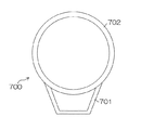
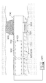
図3(a)、(b)は図1のオーバーチューブの構成を示す長手軸方向の断面図であり、図4は図3(a)の矢印Bから見た矢視図である。図3(a)に示すように、オーバーチューブ700は、光プローブ用チューブ701及び内視鏡用チューブ702により構成される。光プローブ用チューブ701は、細長で筒状部材であって、その先端701aは閉塞され、基端701bは開口されている。また、内視鏡用チューブ702は、光プローブ用チューブ701の外壁に、オーバーチューブ700の長手軸に沿って外周が一体的に結合された円筒状部材から構成され、その先端702a及び基端702bは開口されている。
3A and 3B are longitudinal sectional views showing the configuration of the overtube of FIG. 1, and FIG. 4 is a view as seen from the arrow B of FIG. As shown in FIG. 3A, the
詳細には、光プローブ用チューブ701の先端701aは閉塞(密閉)構造となっており、体内に挿入する際に引っかからないように、テーパ構造となっている。一方、内視鏡用チューブ702の両端は開口となっており、内視鏡100の挿入部114は内視鏡用チューブ702内で進退可能となっており、内視鏡用チューブ702の先端702aより内視鏡100の挿入部114を突出させることができるようになっている。
Specifically, the
なお、光プローブ用チューブ701の先端701aを閉塞した構成としているが、これに限らず、図3(b)に示すように、光プローブ用チューブ701の先端701aを開口した構成としてもよい。
In addition, although it has set as the structure which obstruct | occluded the front-end |
光プローブ用チューブ701は、OCTプローブ600のキャップ622の先端を閉塞した先端内面に当接させた際に、OCTプローブ600の光開口部650が測定光を照射する照射位置を少なくとも含む所定領域Lの外壁全周を切り欠いて開口した測定光L1及び反射光L3を入出射する光入出射窓750が形成されている。すなわち、光入出射窓750は、光プローブ用チューブ701においては外部に開口し、かつ光プローブ用チューブ701と内視鏡用チューブ702とを連通させる。
When the
このように、光プローブ用チューブ701及び内視鏡用チューブ702は、この光入出射窓750において連通しており、光入出射窓750では、図4に示すように、光プローブ用チューブ701の側面から光開口部650を含むプローブ外筒(シース)620、及び内視鏡用チューブ702の内面を見ることができるようになっている。
As described above, the
この結果、内視鏡用チューブ702に内視鏡100の挿入部114が挿通された際には、この内視鏡100により内視鏡用チューブ702の内側から光入出射窓750を介して測定対象Sが撮像可能となっている。
As a result, when the insertion portion 114 of the
なお、光入出射窓750は、OCTプローブ600のキャップ622の先端を閉塞した先端内面に当接させた際に、OCTプローブ600の光開口部650が測定光を照射する照射位置を少なくとも含む所定領域Lに設けるとしたが、これに限らず、上記の照射位置(OCTプローブ600のキャップ622の先端を閉塞した先端内面に当接させた際に、OCTプローブ600の光開口部650が測定光を照射する位置)よりも基端側位置に所定領域L‘(図3(a)参照)を設定し、光入出射窓750を形成するようにしてもよい。この場合、光入出射窓750の位置はオーバーチューブ700の長手軸上にて一意的に決まるので、OCTプローブ600の光開口部650がこの位置に配置されるように、OCTプローブ600の光プローブ用チューブ701への挿入量を調整すればよい。図3(b)に示すように構成した場合(先端701aを開口した構成の場合)も、同様に光入出射窓750の位置を設定すればよい。
The light incident /
図5は図3のA−A線断面を示す断面図である。図5に示すように、オーバーチューブ700の長手軸に直交する面における、光プローブ用チューブ701の断面は略台形に形成され、内視鏡用チューブ702の断面は略円形に形成されている。光プローブ用チューブ701の底面を平面にすることにより測定対象Sとの当接を安定化することが可能となる。
5 is a cross-sectional view showing a cross section taken along line AA of FIG. As shown in FIG. 5, the cross section of the
このように構成された本実施形態では、まず、術者は、OCTプローブ600の挿入部602を光プローブ用チューブ701に挿入すると共に、内視鏡100の挿入部114をオーバーチューブ700の内視鏡用チューブ702内に挿入する。そして、術者は、内視鏡100で画像を見ながら、OCTプローブ600の挿入部602及び内視鏡100の挿入部114を挿通したオーバーチューブ700を患者の体内(管腔内)に挿入する。
In the present embodiment configured as described above, first, the operator inserts the
図6は体腔内での図2のオーバーチューブの配置例を示す図である。図6に示すように、術者は、体内(管腔内)にて測定対象Sである患部を内視鏡画像から見つけたところで、オーバーチューブ700を回転させ光入出射窓750側が測定対象Sの方に向くように調整し、測定対象Sに光プローブ用チューブ701の外壁を当接させる。この状態で、OCTプローブ600の内部にある光ファイバ623と光学レンズ628が回転しながら長手軸方向に移動し、2次元的な走査が行われる(図2参照)。OCT計測では深さ方向の情報が得られるため、結果的に測定対象Sの3次元構造のデータが取得される。
FIG. 6 is a view showing an arrangement example of the overtube of FIG. 2 in the body cavity. As shown in FIG. 6, when the surgeon finds the affected part that is the measurement target S in the body (in the lumen) from the endoscopic image, the operator rotates the
本実施形態では、上述したように、オーバーチューブ700は光プローブ用チューブ701及び内視鏡用チューブ702より構成されるため、オーバーチューブ700全体の剛性が高まり、このオーバーチューブ700全体の剛性により安定して測定対象Sに光入出射窓750側の光プローブ用チューブ701の外壁を当接させることができる。
In the present embodiment, as described above, since the
すなわち、オーバーチューブ700は、光開口部650と測定対象Sとの間隙を所定の間隙D(図6参照)に安定的に保持した所望の観察位置より、測定対象Sに対して測定光を集光させることができ、測定対象Sからの光をOCTプロセッサ400に導波することで、該測定対象Sの3次元構造のデータを取得し測定対象Sの光断層像を得ることを可能とする。
That is, the
また、内視鏡用チューブ702に内視鏡100の挿入部114を挿通した状態、すなわち内視鏡観察下では、さらにオーバーチューブ700の全体の剛性が高まり、また、挿入部114の湾曲部142の湾曲操作を利用して、より光プローブ用チューブ701の外壁と測定対象Sとの当接位置を安定的に保持することもできる。
In addition, when the insertion portion 114 of the
図7は図3の内視鏡用チューブに挿入した内視鏡が撮像した内視鏡用チューブからの光入出射窓の画像の一例を示す図である。本実施形態では、内視鏡100の先端面を内視鏡用チューブ702内で光入出射窓750よりも基端側に配置することで、図7に示すように、内視鏡用チューブ702に挿入した内視鏡100により光入出射窓750を介して、光プローブ用チューブ701に挿入したOCTプローブ600及びその下にある測定対象Sの内視鏡画像790を得ることができ、OCT計測を行う部位である測定対象Sに光開口部650を、内視鏡100で観察しながら合わせられる。また、内視鏡100の鉗子チャンネル(不図示)に処置具(不図示)を挿通させ、該処置具(不図示)を光入出射窓750を介して測定対象Sにアプローチさせることも可能であり、容易かつ確実にOCT計測した測定対象Sを生検、あるいは治療することができる。
FIG. 7 is a diagram illustrating an example of an image of a light incident / exit window from the endoscope tube captured by the endoscope inserted into the endoscope tube of FIG. 3. In the present embodiment, the distal end surface of the
図8は図3のA−A線断面の変形例を示す断面図である。図8に示すように、オーバーチューブ700の長手軸に直交する面における、光プローブ用チューブ701の断面を略半円形に形成してもよい。
FIG. 8 is a cross-sectional view showing a modification of the cross section taken along the line AA of FIG. As shown in FIG. 8, the cross section of the
第2の実施形態:
第2の実施形態は第1の実施形態とほとんど同じであるので、異なる構成のみ説明し、同一構成には同じ符号を付し説明は省略する。
Second embodiment:
Since the second embodiment is almost the same as the first embodiment, only different configurations will be described.
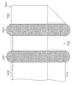
図9は第2の実施形態に係るオーバーチューブの構成を示す図であり、図10は図9の凸部と光入出射窓との位置関係を示す図である。 FIG. 9 is a diagram illustrating a configuration of the overtube according to the second embodiment, and FIG. 10 is a diagram illustrating a positional relationship between the convex portion and the light incident / exit window in FIG. 9.
本実施形態では、図9に示すように、オーバーチューブ700の光入出射窓750の前後の位置(基端側位置及び先端側位置:図10参照)に例えば高さがΔdの凸部800が形成されている。その他の構成は第1の実施形態と同じである。
In the present embodiment, as shown in FIG. 9,
図9に示すように、本実施形態では、第1の実施形態と同様に、まず、術者は、OCTプローブ600の挿入部602を光プローブ用チューブ701に挿入すると共に、内視鏡100の挿入部114をオーバーチューブ700の内視鏡用チューブ702内に挿入する。そして、術者は、内視鏡100で画像を見ながら、OCTプローブ600の挿入部602及び内視鏡100の挿入部114を挿通したオーバーチューブ700を患者の体内(管腔内)に挿入する。術者は、体内(管腔内)にて測定対象Sである患部を内視鏡画像から見つけたところで、オーバーチューブ700を回転させ光入出射窓750側が測定対象Sの方に向くように調整し、測定対象Sに光プローブ用チューブ701の外壁を押し付ける。光開口部650は、凸部800のために測定対象Sからは、所望の観察位置である、例えば光開口部650と光プローブ用チューブ701の外壁までの距離をDとした場合、D+Δdだけ浮いた状態に位置することになる。この状態で、OCTプローブ600の内部にある光ファイバ623と光学レンズ628が回転しながら長手軸方向に移動し、2次元的な走査が行われる。OCT計測では深さ方向の情報が得られるため、結果的に測定対象Sの3次元構造のデータが取得される。
As shown in FIG. 9, in this embodiment, as in the first embodiment, first, the operator inserts the
このように本実施形態では、第1の実施形態の効果に加え、凸部800により光開口部650と測定対象Sとの距離(間隙)を所望の距離(D+Δd)を確保し所望の観察位置から計測することができるので、第1の実施形態が測定対象Sの比較的深い層部分の3次元構造のデータを取得したのに対して、本実施形態では例えば測定対象Sのより表層部分の3次元構造のデータが取得できる。すなわち、本実施形態では凸部800の高さΔdに基づいた所望の観察位置から計測し、測定対象Sの所望の深さの層部分の3次元構造のデータが取得できる。また、本実施形態ではこの凸部800により、測定対象Sの表面を潰すことなくOCT計測することができる。
As described above, in the present embodiment, in addition to the effects of the first embodiment, a desired distance (D + Δd) is secured as a distance (gap) between the
第3の実施形態:
第3の実施形態は第1の実施形態とほとんど同じであるので、異なる構成のみ説明し、同一構成には同じ符号を付し説明は省略する。
Third embodiment:
Since the third embodiment is almost the same as the first embodiment, only different configurations will be described, the same reference numerals are given to the same configurations, and descriptions thereof will be omitted.
図11は第3の実施形態に係るオーバーチューブの構成を示す図である。本実施形態では、図11に示すように、オーバーチューブ700の測定対象Sと当接させる位置に対向する側の内視鏡用チューブ702の側面にバルーン900が設けられ、このバルーン900を膨張/収縮させるためのバルーン制御手段であるバルーン制御装置901が長手軸に沿って内視鏡用チューブ702の側面内に設けられた送気路902を介してバルーン900に接続されて構成される。その他の構成は第1の実施形態と同じである。
FIG. 11 is a diagram illustrating a configuration of an overtube according to the third embodiment. In the present embodiment, as shown in FIG. 11, a
図11に示すように、本実施形態では、第1の実施形態と同様に、まず、術者は、OCTプローブ600の挿入部602を光プローブ用チューブ701に挿入すると共に、内視鏡100の挿入部114をオーバーチューブ700の内視鏡用チューブ702内に挿入する。そして、術者は、内視鏡100で画像を見ながら、OCTプローブ600の挿入部602及び内視鏡100の挿入部114を挿通したオーバーチューブ700を患者の体内(管腔内)に挿入する。
As shown in FIG. 11, in the present embodiment, as in the first embodiment, first, the operator inserts the
術者は、体内(管腔内)にて測定対象Sである患部を内視鏡画像から見つけたところで、オーバーチューブ700を回転させ光入出射窓750側が測定対象Sの方に向くように調整し、測定対象Sに光プローブ用チューブ701の外壁を当接させる。
When the surgeon finds the affected area as the measurement target S from the endoscopic image in the body (inside the lumen), the operator rotates the
そして、本実施形態では、バルーン制御装置901を操作しバルーン900を膨らませてオーバーチューブ700を管腔内壁に押し当てて、測定対象Sと光プローブ用チューブ701の外壁との当接部分を固定する。この状態で、OCTプローブ600の内部にある光ファイバ623と光学レンズ628が回転しながら長手軸方向に移動し、2次元的な走査が行われる。OCT計測では深さ方向の情報が得られるため、結果的に測定対象Sの3次元構造のデータが取得される。
In this embodiment, the
このように本実施形態では、第1の実施形態の効果に加え、オーバーチューブ700を測定対象Sにバルーン900で固定したまま、内視鏡用チューブ702に入る範囲で内視鏡を交換することができる。
As described above, in the present embodiment, in addition to the effects of the first embodiment, the endoscope is replaced within the range of entering the
例えば、患者の体内に挿入する際には通常観察、もしくは特殊光観察が可能な内視鏡を用い、測定対象Sの位置が特定できたのちに、処置具を挿入できる内視鏡に交換して、測定対象Sの処置をすることができる。 For example, when inserting into a patient's body, an endoscope capable of normal observation or special light observation is used, and after the position of the measuring object S is identified, the endoscope is replaced with an endoscope into which a treatment instrument can be inserted. Thus, the measuring object S can be treated.
図示はしないが、例えば、肺(気管支)の末梢部の生検には、内視鏡用チューブ702の内径が例えば1.0mmのオーバーチューブ700を用いる。そして、この内径1.0mmのチューブ部材610に例えば直径0・8mmの細径の内視鏡100を挿入する。この内視鏡用チューブ702には鉗子口がなく、蛍光観察用の照明光部と観察用カメラがつけられている。この内視鏡100で観察しながら、肺(気管支)の末梢部へと挿入する。蛍光観察を併用しながら病変部らしき場所を見つけたところで、その場所をOCT測定する。OCT測定により壁面の肥厚や変質が確認される。バルーン900を膨らませることで、その場所にオーバーチューブ700を留置したまま、内視鏡100を内視鏡用チューブ702から引き抜く。そして、内視鏡用チューブ702に内視鏡100に代わる生検鉗子を通し、OCT測定した測定対象Sを生検する。これにより、高精度で病変部の生検が可能となる。なお、内視鏡用チューブ702には内視鏡100を残し、光プローブ用チューブ701にOCTプローブ600の代わりに生検鉗子を通してもよい。
Although not shown, for example, for the biopsy of the peripheral part of the lung (bronchi), an
なお、本実施形態においても、図示はしないが、第2の実施形態と同様に、オーバーチューブ700の光入出射窓750の前後の位置に凸部800を形成してオーバーチューブ700を構成してもよく、この場合、第2の実施形態と同様な作用・効果を得ることができる。
In this embodiment, although not shown, the
図12は図11のオーバーチューブの第1の変形例の構成を示す図である。図12に示すように、凸部800をバルーン810,811により構成してもよく、バルーン制御装置901を操作しバルーン900,810,811を膨らませてオーバーチューブ700を固定することができる。この場合、まず、バルーン900及び測定対象Sの先にて先端側の第1のバルーン810を膨張させオーバーチューブ700を固定する。そして、オーバーチューブ700を測定対象Sに対して押し込むことで、測定対象S付近をしっかりと伸ばす。測定対象S付近伸ばした所で、基端側の第2のバルーン811を膨らませて固定する。これにより、測定対象S周辺がたるんでいる場合に測定対象Sがバルーン810,811の間に入り込むことを防ぐことができる。
FIG. 12 is a diagram showing a configuration of a first modification of the overtube of FIG. As shown in FIG. 12, the
図13は図11のオーバーチューブの第2の変形例の構成を示す図である。本実施形態においては、図13に示すように、バルーン900,810,811の代わりに2本のリング状のバルーン820,821を光入出射窓750の前後に位置に設け、バルーン制御部901を操作しバルーン820,821を膨らませてオーバーチューブ700を固定するようにしてもよく、上記第1の変形例(図12参照)と同様な作用・効果を得ることができる。
FIG. 13 is a view showing a configuration of a second modification of the overtube of FIG. In this embodiment, as shown in FIG. 13, two ring-shaped
なお、上記各実施形態では、オーバーチューブ700を光プローブ用チューブ701と、この光プローブ用チューブ701の外壁に、オーバーチューブ700の長手軸に沿って外周が一体的に結合された内視鏡用チューブ702とから構成する(図3及び図5参照)としたが、これに限らない。
In each of the above embodiments, the
図14は本発明に係るオーバーチューブの変形例1の構成を示す断面図であり、図15は本発明に係るオーバーチューブの変形例2の構成を示す断面図である。
FIG. 14 is a cross-sectional view showing a configuration of
例えば、オーバーチューブ700の長手軸に直交する面において、図14に示すように、内視鏡用チューブ702の内層とし、内視鏡用チューブ702の外層に断面形状を内視鏡用チューブ702の外周に沿った長穴形状とした光プローブ用チューブ701を形成した層構造のオーバーチューブ700としてもよい。ここで、この光プローブ用チューブ701内でOCTプローブ600を図14中矢印Cのように、オーバーチューブ700の長手軸に直交する面においてスライドさせることのできるスライド機構を設けることが好ましい。OCTプローブ600をスライドさせることで、より広範囲なOCT計測が可能となる。なお、この場合も、光プローブ用チューブ701においては外部に開口し、かつ光プローブ用チューブ701と内視鏡用チューブ702とを連通させる光入出射窓750が形成されている。
For example, on the surface orthogonal to the longitudinal axis of the
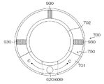
また、オーバーチューブ700の長手軸に直交する面において、図15に示すように、内視鏡用チューブ702の内層とし、内視鏡用チューブ702の中心軸を略中心軸とした同軸層の光プローブ用チューブ701を形成した2層構造のオーバーチューブ700としてもよい。この場合も、この光プローブ用チューブ701内でOCTプローブ600を図14中矢印Cのように、オーバーチューブ700の長手軸に直交する面においてスライドさせることのできるスライド機構を設けることが好ましい。OCTプローブ600をスライドさせることで、より広範囲なOCT計測が可能となる。なお、2層構造を保持するために光プローブ用チューブ701内には層構造保持部930が所定の位置に形成されている。また、この場合も、光プローブ用チューブ701においては外部に開口し、かつ光プローブ用チューブ701と内視鏡用チューブ702とを連通させる光入出射窓750が形成されている。
Further, as shown in FIG. 15, in the plane orthogonal to the longitudinal axis of the
図16は本発明に係る光プローブ用チューブの変形例の構成を示す図である。上記各実施形態においては、図16に示すように、光プローブ用チューブ701の先端内面に一端が固定されたガイドワイヤ940をオーバーチューブ700の長手軸に沿って光プローブ用チューブ701内に配設することが好ましい。このガイドワイヤ940をガイドにOCTプローブ600を光プローブ用チューブ701内に挿通することで、OCTプローブ600が光入出射窓750に引っかかることなく、OCTプローブ600の先端を光プローブ用チューブ701の先端内面に当接させることが可能となる。
FIG. 16 is a view showing a configuration of a modification of the optical probe tube according to the present invention. In each of the above embodiments, as shown in FIG. 16, a
図17は第1ないし第3の実施形態における内視鏡用チューブの変形例の構成を示す図である。上記各実施形態の内視鏡用チューブ702においては、図17に示すように、先端部に開閉可能なミラー部950を配置するとより望ましい。この場合、体内に挿入する時や通常の内視鏡観察時は開としておき、ミラー部950が前方の観察に邪魔にならないようにする。OCT測定前に測定対象Sにオーバーチューブ700を押しつける時にはミラー部950を閉とする。ミラー部950を閉とすると、内視鏡前方に45度の角度でミラー部950が覆い被さる。そのため、光入出射窓750を介して内視鏡用チューブ702下面が観察可能となり、測定場所に位置あわせや観察に便利である。
FIG. 17 is a diagram showing a configuration of a modification of the endoscope tube in the first to third embodiments. In the
以上、本発明の光プローブ用オーバーチューブについて詳細に説明したが、本発明は、以上の例には限定されず、本発明の要旨を逸脱しない範囲において、各種の改良や変形を行ってもよいのはもちろんである。 As mentioned above, although the overtube for optical probes of this invention was demonstrated in detail, this invention is not limited to the above example, You may perform various improvement and deformation | transformation in the range which does not deviate from the summary of this invention. Of course.
10…画像診断装置、100…内視鏡、114,602…挿入部、200…内視鏡プロセッサ、230…画像合成部、300…光源装置、400…OCTプロセッサ、500…モニタ装置、600…OCTプローブ、623…光ファイバ、628…光学レンズ、650…光開口部、700…オーバーチューブ、701…光プローブ用チューブ 702…内視鏡用チューブ、750…光入出射窓
DESCRIPTION OF
Claims (17)
基端及び先端が開口し、前記第1の挿通路の長手軸に沿って前記第1の挿通路と一体的に結合された筒状の第2の挿通路と、
を備え、
前記第1の挿通路の長手軸に沿った先端側の所定位置を含む所定領域に、前記第1の挿通路の外壁部分を切り欠いて外部に開口し、かつ前記第1の挿通路と前記第2の挿通路とを連通させた光入出射窓を形成した
ことを特徴とする光プローブ用オーバーチューブ。 A cylindrical first insertion path for inserting an optical probe having an elongated insertion portion having a light irradiation means for irradiating measurement light at least in the radial direction in the distal end portion;
A cylindrical second insertion passage having a proximal end and a distal end opened and integrally coupled to the first insertion passage along a longitudinal axis of the first insertion passage;
With
In a predetermined region including a predetermined position on the distal end side along the longitudinal axis of the first insertion passage, an outer wall portion of the first insertion passage is cut out and opened to the outside, and the first insertion passage and the first insertion passage An over-tube for an optical probe, characterized in that a light entrance / exit window communicating with the second insertion passage is formed.
前記所定位置は、前記光プローブが挿入されて該光プローブの先端が前記第1の挿通路の閉塞された先端内面に当接した際の、前記光照射手段の前記測定光の照射位置、あるいは該照射位置より前記第1の挿通路の長手軸に沿った基端側位置である
ことを特徴とする請求項1に記載の光プローブ用オーバーチューブ。 The first insertion passage has a proximal end opened and a distal end closed,
The predetermined position is the measurement light irradiation position of the light irradiation means when the optical probe is inserted and the tip of the optical probe comes into contact with the closed inner surface of the first insertion path, or 2. The overtube for an optical probe according to claim 1, wherein the overtube for an optical probe is a base end side position along a longitudinal axis of the first insertion path from the irradiation position.
前記光入出射窓は、前記所定領域の前記第1の挿通路の外壁全周部分を切り欠いて開口して形成される
ことを特徴とする請求項1または2に記載の光プローブ用オーバーチューブ。 The outer wall of the second insertion passage is formed integrally with the outer wall of the first insertion passage along the longitudinal axis,
3. The overtube for an optical probe according to claim 1, wherein the light incident / exit window is formed by opening and cutting an entire outer wall portion of the first insertion path in the predetermined region. .
ことを特徴とする請求項1ないし3のいずれか1つに記載の光プローブ用オーバーチューブ。 The overtube for an optical probe according to any one of claims 1 to 3, wherein the second insertion passage is an endoscope outer tube into which at least an endoscope insertion portion can be inserted.
ことを特徴とする請求項1ないし4のいずれか1つに記載の光プローブ用オーバーチューブ。 The overtube for an optical probe according to any one of claims 1 to 4, wherein an inner surface shape of a cross section perpendicular to the longitudinal axis of the first insertion path is a substantially trapezoid.
ことを特徴とする請求項1ないし4のいずれか1つに記載の光プローブ用オーバーチューブ。 The overtube for an optical probe according to any one of claims 1 to 4, wherein an inner surface shape of a cross section perpendicular to the longitudinal axis of the first insertion path is a substantially semicircular shape.
ことを特徴とする請求項1または2に記載の光プローブ用オーバーチューブ。 The first insertion path and the second insertion path have a layer structure, and the first insertion path is formed in an outer layer of the second insertion path. The overtube for optical probes as described.
ことを特徴とする請求項7に記載の光プローブ用オーバーチューブ。 The overtube for an optical probe according to claim 7, wherein the first insertion path and the second insertion path have a substantially cylindrical shape with a two-layer structure in which a central axis is substantially coaxial.
ことを特徴とする請求項7に記載の光プローブ用オーバーチューブ。 The overtube for an optical probe according to claim 7, wherein a cross-sectional shape of the first insertion passage perpendicular to the longitudinal axis is a long hole shape along an outer periphery of the second insertion passage.
ことを特徴とする請求項1ないし9のいずれか1つに記載の光プローブ用オーバーチューブ。 The overtube for an optical probe according to any one of claims 1 to 9, wherein the first insertion path has a convex portion on an outer surface in the vicinity of the light incident / exit window.
ことを特徴とする請求項1ないし9のいずれか1つに記載の光プローブ用オーバーチューブ。 The second insertion path further includes balloon means that can be inflated and deflated at an outer peripheral position facing the light entrance / exit window, and further includes balloon control means for controlling expansion and contraction of the balloon means. The overtube for optical probes according to any one of claims 1 to 9.
ことを特徴とする請求項10に記載の光プローブ用オーバーチューブ。 The second insertion path further includes balloon means that can be inflated and deflated at an outer peripheral position facing the light entrance / exit window, and further includes balloon control means for controlling expansion and contraction of the balloon means. The overtube for an optical probe according to claim 10.
ことを特徴とする請求項12に記載の光プローブ用オーバーチューブ。 The overtube for an optical probe according to claim 12, wherein the convex portion is a balloon portion that can be inflated and deflated.
ことを特徴とする請求項13に記載の光プローブ用オーバーチューブ。 The overtube for an optical probe according to claim 13, wherein the balloon portion is formed integrally with the balloon means.
ことを特徴とする請求項13または14に記載の光プローブ用オーバーチューブ。 The over-tube for an optical probe according to claim 13 or 14, wherein the balloon control means further controls expansion and contraction of the balloon portion.
ことを特徴とする請求項1ないし15のいずれか1つに記載の光プローブ用オーバーチューブ。 16. The guide wire according to claim 1, further comprising a guide wire having one end fixed to the inner surface of the distal end of the first insertion passage and provided in the first insertion passage along the longitudinal axis. The overtube for optical probes as described in any one.
ことを特徴とする請求項1ないし16のいずれか1つに記載の光プローブ用オーバーチューブ。 The overtube for an optical probe according to any one of claims 1 to 16, wherein a tip end of the closed first insertion path has a tapered shape.
Priority Applications (1)
| Application Number | Priority Date | Filing Date | Title |
|---|---|---|---|
| JP2008324605A JP2010142496A (en) | 2008-12-19 | 2008-12-19 | Overtube for optical probe |
Applications Claiming Priority (1)
| Application Number | Priority Date | Filing Date | Title |
|---|---|---|---|
| JP2008324605A JP2010142496A (en) | 2008-12-19 | 2008-12-19 | Overtube for optical probe |
Publications (1)
| Publication Number | Publication Date |
|---|---|
| JP2010142496A true JP2010142496A (en) | 2010-07-01 |
Family
ID=42563532
Family Applications (1)
| Application Number | Title | Priority Date | Filing Date |
|---|---|---|---|
| JP2008324605A Ceased JP2010142496A (en) | 2008-12-19 | 2008-12-19 | Overtube for optical probe |
Country Status (1)
| Country | Link |
|---|---|
| JP (1) | JP2010142496A (en) |
Cited By (1)
| Publication number | Priority date | Publication date | Assignee | Title |
|---|---|---|---|---|
| CN104718483A (en) * | 2012-10-04 | 2015-06-17 | 西澳大利亚大学 | A method and system for characterising biological tissue |
Citations (6)
| Publication number | Priority date | Publication date | Assignee | Title |
|---|---|---|---|---|
| JPH1156772A (en) * | 1997-08-22 | 1999-03-02 | Olympus Optical Co Ltd | Optical tomograph |
| JP2003284674A (en) * | 2002-03-28 | 2003-10-07 | Fuji Photo Optical Co Ltd | Cover type endoscope |
| JP2005103140A (en) * | 2003-10-01 | 2005-04-21 | Olympus Corp | Insertion aid for treatment of large intestine whole layer resection, and medical instrument system thereof |
| JP2005168990A (en) * | 2003-12-15 | 2005-06-30 | Yamamoto Hironori | Over-tube for endoscope apparatus |
| JP2008183208A (en) * | 2007-01-30 | 2008-08-14 | Hoya Corp | Oct probe and oct system |
| JP2008538709A (en) * | 2005-04-15 | 2008-11-06 | ネオガイド システムズ, インコーポレイテッド | Instrument with external working channel |
-
2008
- 2008-12-19 JP JP2008324605A patent/JP2010142496A/en not_active Ceased
Patent Citations (6)
| Publication number | Priority date | Publication date | Assignee | Title |
|---|---|---|---|---|
| JPH1156772A (en) * | 1997-08-22 | 1999-03-02 | Olympus Optical Co Ltd | Optical tomograph |
| JP2003284674A (en) * | 2002-03-28 | 2003-10-07 | Fuji Photo Optical Co Ltd | Cover type endoscope |
| JP2005103140A (en) * | 2003-10-01 | 2005-04-21 | Olympus Corp | Insertion aid for treatment of large intestine whole layer resection, and medical instrument system thereof |
| JP2005168990A (en) * | 2003-12-15 | 2005-06-30 | Yamamoto Hironori | Over-tube for endoscope apparatus |
| JP2008538709A (en) * | 2005-04-15 | 2008-11-06 | ネオガイド システムズ, インコーポレイテッド | Instrument with external working channel |
| JP2008183208A (en) * | 2007-01-30 | 2008-08-14 | Hoya Corp | Oct probe and oct system |
Cited By (2)
| Publication number | Priority date | Publication date | Assignee | Title |
|---|---|---|---|---|
| CN104718483A (en) * | 2012-10-04 | 2015-06-17 | 西澳大利亚大学 | A method and system for characterising biological tissue |
| US10232106B2 (en) | 2012-10-04 | 2019-03-19 | The Unversity of Western Australia | Method and system for characterising biological tissue |
Similar Documents
| Publication | Publication Date | Title |
|---|---|---|
| WO2010071057A1 (en) | Optical probe and optical observation device | |
| JP2022016610A (en) | Method and system for optically imaging epithelial luminal organ by beam scanning | |
| US10258226B2 (en) | Imaging system producing multiple registered images of a body lumen | |
| US8876730B2 (en) | Diagnostic or treatment tool for colonoscopy | |
| US20110077463A1 (en) | Optical probe and endoscope apparatus | |
| JP5976924B2 (en) | Endoscopic surgical device | |
| Adams et al. | Advances in endoscopic optical coherence tomography catheter designs | |
| JP2011072401A (en) | Optical probe and endoscope apparatus | |
| JP2008200283A (en) | Optical probe and optical tomographic image acquiring apparatus | |
| JP5389426B2 (en) | Optical probe device and operating method thereof | |
| JP2010051390A (en) | Device and method for acquiring optical tomographic image | |
| JP5006591B2 (en) | Ultrasound endoscope | |
| JP5939746B2 (en) | Optical tomography probe | |
| JP4864603B2 (en) | Ultrasound endoscope | |
| JP5959723B2 (en) | Endoscopic surgical device | |
| JP2010142496A (en) | Overtube for optical probe | |
| WO2012014919A1 (en) | Optical probe and optical tomographic imaging device | |
| JP5887222B2 (en) | Endoscope apparatus and endoscope system | |
| JP2011072402A (en) | Optical probe and endoscope apparatus | |
| JP2012050609A (en) | Image diagnostic apparatus and image diagnostic method | |
| WO2012029685A1 (en) | Probe pressing component for image diagnostic device | |
| JP2012050487A (en) | Probe | |
| JP2010042139A (en) | Ultrasonic endoscope | |
| JP2008200098A (en) | Treatment tool for endoscope and system using this treatment tool | |
| JP2010125273A (en) | Probe and oct apparatus |
Legal Events
| Date | Code | Title | Description |
|---|---|---|---|
| A621 | Written request for application examination |
Free format text: JAPANESE INTERMEDIATE CODE: A621 Effective date: 20110809 |
|
| A977 | Report on retrieval |
Free format text: JAPANESE INTERMEDIATE CODE: A971007 Effective date: 20130314 |
|
| A131 | Notification of reasons for refusal |
Free format text: JAPANESE INTERMEDIATE CODE: A131 Effective date: 20130326 |
|
| A521 | Written amendment |
Free format text: JAPANESE INTERMEDIATE CODE: A523 Effective date: 20130523 |
|
| A01 | Written decision to grant a patent or to grant a registration (utility model) |
Free format text: JAPANESE INTERMEDIATE CODE: A01 Effective date: 20130829 |
|
| A045 | Written measure of dismissal of application |
Free format text: JAPANESE INTERMEDIATE CODE: A045 Effective date: 20131220 |