JP2010142340A - Electric toilet seat device - Google Patents
Electric toilet seat device Download PDFInfo
- Publication number
- JP2010142340A JP2010142340A JP2008320766A JP2008320766A JP2010142340A JP 2010142340 A JP2010142340 A JP 2010142340A JP 2008320766 A JP2008320766 A JP 2008320766A JP 2008320766 A JP2008320766 A JP 2008320766A JP 2010142340 A JP2010142340 A JP 2010142340A
- Authority
- JP
- Japan
- Prior art keywords
- motor
- toilet seat
- rotating member
- worm
- torque
- Prior art date
- Legal status (The legal status is an assumption and is not a legal conclusion. Google has not performed a legal analysis and makes no representation as to the accuracy of the status listed.)
- Granted
Links
Images


Landscapes
- Toilet Supplies (AREA)
- Gear Transmission (AREA)
- Transmission Devices (AREA)
Abstract
【課題】過大トルクを遮断出来る省スペースな電動便座装置を提供すること。
【解決手段】モータ41と、モータ41の出力を減速する減速機構44と、その出力で回動される便座と、モータ41と便座との間で過大なトルク荷重の伝達を遮断するトルクリミッタ50と、を備えた便座の電動開閉装置14であって、トルクリミッタ50は、コイルバネ54と、コイルバネ54が係止される外輪51と、コイルバネ54に弾性付勢され、被駆動部材に所定荷重以上のトルク荷重が加えられるとコイルバネ54に対して相対回転する内輪53と、を備え、内輪53は歯車列45のウォーム51aに固定され、外輪51にはモータ41からの出力が伝達される。便座11を外力により閉方向に付勢する際にウォーム51aに付勢される力が外輪51及び内輪53の間を遠ざける方向に作用するように、歯車列を構成する。
【選択図】図6A space-saving electric toilet seat device capable of interrupting excessive torque is provided.
A motor 41, a speed reduction mechanism 44 that decelerates the output of the motor 41, a toilet seat that is rotated by the output, and a torque limiter 50 that blocks transmission of an excessive torque load between the motor 41 and the toilet seat. The torque limiter 50 is elastically biased by the coil spring 54, the outer ring 51 to which the coil spring 54 is locked, and the coil spring 54, and the driven member has a predetermined load or more. The inner ring 53 is fixed to a worm 51a of the gear train 45, and the output from the motor 41 is transmitted to the outer ring 51. The gear train is configured such that when the toilet seat 11 is urged in the closing direction by an external force, the force urged by the worm 51 a acts in a direction away from the outer ring 51 and the inner ring 53.
[Selection] Figure 6
Description
本発明はトルクリミッタを備えた電動便座装置に関するものである。 The present invention relates to an electric toilet seat device provided with a torque limiter.
従来の電動便座装置では、駆動モータの出力軸と歯車の間、又は、駆動モータの出力軸に固定した歯車が噛み合う減速歯車列の歯車にトルクリミッタ機構が構成されている。よって、駆動モータの動作中に便座や便蓋に大きな外力が加えられても、駆動モータや減速歯車列に過大なトルク荷重が伝わらない(例えば、特許文献1参照。)。
しかしながら、従来の電動便座装置では、遊星歯車機構を備えた減速歯車列を用いて駆動モータの出力を減速しているために、部品点数が多く複雑な構造となっている。また、従来の電動便座装置のように、トルクリミッタ機構を駆動モータの出力軸と歯車との間及び遊星歯車機構内の二箇所に設けた場合、さらに部品点数が多く複雑な構造となってしまい、コストアップにもつながる。 However, in the conventional electric toilet seat device, since the output of the drive motor is reduced using a reduction gear train provided with a planetary gear mechanism, the number of parts is complicated. Moreover, when the torque limiter mechanism is provided between the output shaft of the drive motor and the gear and at two places in the planetary gear mechanism as in the conventional electric toilet seat device, the number of parts is further complicated and the structure is complicated. This also leads to cost increase.
本発明は、大きなトルク荷重の伝達を遮断出来るトルクリミッタを備えた省スペースな電動便座装置を提供することを目的とする。 An object of the present invention is to provide a space-saving electric toilet seat device including a torque limiter capable of interrupting transmission of a large torque load.
上記課題を解決する請求項1に係る電動便座装置の特徴は、モータと、
該モータの出力により回転を行うウォームと、
該ウォームと噛合し前記ウォームの回転を減速して、便座及び便蓋の少なくとも1つの被駆動部材を開閉動作させる減速機構と、
前記被駆動部材に対して所定荷重以上の外力が作用した場合に、前記モータへのトルク伝達を遮断するトルクリミッタとを備えた電動便座装置において、
前記トルクリミッタは、
前記ウォームと一体回転する第1回転部材と、
前記モータの出力と一体回転を行う第2回転部材と
前記第1回転部材及び前記第2回転部材のうちの一方の部材に係止され、他方の部材の外周に締着され、前記所定荷重以上に外力が作用した場合には前記第1回転部材及び前記第2回転部材の間を相対回転させる弾性部材とを備え、
前記被駆動部材に対して閉方向の外力が作用した場合に、前記第1回転部材と前記第2回転部材とが離間することにより前記モータへのトルク伝達を遮断することにある。
The feature of the electric toilet seat device according to claim 1 for solving the above-described problems is a motor,
A worm that rotates according to the output of the motor;
A speed reduction mechanism that meshes with the worm and decelerates rotation of the worm to open and close at least one driven member of the toilet seat and toilet lid;
In an electric toilet seat device comprising a torque limiter for interrupting torque transmission to the motor when an external force of a predetermined load or more is applied to the driven member,
The torque limiter is
A first rotating member that rotates integrally with the worm;
A second rotating member that rotates integrally with the output of the motor, and is locked to one member of the first rotating member and the second rotating member, and is fastened to the outer periphery of the other member so that the predetermined load or more is reached. And an elastic member that relatively rotates between the first rotating member and the second rotating member when an external force is applied thereto,
When an external force in the closing direction is applied to the driven member, torque transmission to the motor is interrupted by separating the first rotating member and the second rotating member.
上記課題を解決する請求項2に係る電動便座装置の特徴は、請求項1において、前記荷重以上の外力が作用した場合に、前記ウォームを前記モータから離隔する方向に前記外力を伝達する前記減速機構を有し、
前記第2回転部材は、前記モータと前記第1回転部材との間に配設されることにある。
A feature of the electric toilet seat device according to claim 2 that solves the above-mentioned problem is that the deceleration according to claim 1 that transmits the external force in a direction separating the worm from the motor when an external force greater than the load is applied. Has a mechanism,
The second rotating member is disposed between the motor and the first rotating member.
上記課題を解決する請求項3に係る電動便座装置の特徴は、請求項1において、前記荷重以上の外力が作用した場合に、前記ウォームを前記モータが配置される方向に前記外力を伝達する前記減速機構を有し、
前記第1回転部材は、前記モータと前記第2回転部材との間に配設されることにある。
A feature of the electric toilet seat device according to claim 3 for solving the above-described problem is that in claim 1, when an external force greater than the load is applied, the external force is transmitted to the worm in a direction in which the motor is disposed. A reduction mechanism,
The first rotating member is disposed between the motor and the second rotating member.
上記課題を解決する請求項4に係る電動便座装置の特徴は、請求項1〜3の何れか1項において、前記モータに対して、前記第1回転部材と前記第2回転部材は同軸に配設されることにある。 A feature of the electric toilet seat device according to claim 4 for solving the above problem is that in any one of claims 1 to 3, the first rotating member and the second rotating member are arranged coaxially with respect to the motor. It is to be established.
上記課題を解決する請求項5に係る電動便座装置の特徴は、請求項1〜4の何れか1項において、前記ウォームと前記第1回転部材は一体で形成されることにある。 A feature of the electric toilet seat device according to claim 5 that solves the above-described problem is that, in any one of claims 1 to 4, the worm and the first rotating member are integrally formed.
請求項1に記載の発明では、電動便座装置はモータの出力軸と減速機構の歯車列の一番目であるウォームとの間にトルクリミッタを備える。通常の運転状態においてはトルクリミッタが備える第1回転部材及び第2回転部材のうちの一方の部材に固定された弾性部材は他方の部材の外周に締着されており、第1回転部材及び第2回転部材の間におけるトルクの伝達が為されるが、便座又は便蓋に所定荷重以上の外力が加えられてトルクリミッタに大きなトルク荷重が生じると、トルクリミッタが備える第1回転部材及び第2回転部材のうちの一方の部材に係止された弾性部材が他方の部材に対して相対回転可能になるので、モータの出力軸には所定荷重以上の外力に起因するトルク荷重が遮断される。また、モータの出力軸に所定荷重の大きさ以上のトルク荷重が伝達された場合にも減速機構がモータから受ける反力が生じるのを防ぐことが出来る。よって、モータや減速機構等の破損を防ぐことが出来る。 In the first aspect of the present invention, the electric toilet seat device includes a torque limiter between the output shaft of the motor and the worm that is the first gear train of the speed reduction mechanism. In a normal operation state, the elastic member fixed to one of the first rotating member and the second rotating member included in the torque limiter is fastened to the outer periphery of the other member, and the first rotating member and the second rotating member Torque is transmitted between the two rotating members. When an external force greater than a predetermined load is applied to the toilet seat or the toilet lid and a large torque load is generated in the torque limiter, the first rotating member and the second rotating member included in the torque limiter are generated. Since the elastic member locked to one member of the rotating members can be rotated relative to the other member, a torque load caused by an external force exceeding a predetermined load is cut off from the output shaft of the motor. Further, it is possible to prevent the reaction force that the reduction mechanism receives from the motor from being generated even when a torque load greater than a predetermined load is transmitted to the output shaft of the motor. Therefore, damage to the motor and the speed reduction mechanism can be prevented.
また、トルクリミッタがモータの出力軸と減速機構のウォームとの間に備えられるので、減速機構の歯車列の中や減速機構と便座又は便蓋との間に設けられる場合と比べて、トルクリミッタが作動するトルク荷重の設定を小さくすることが出来る。よって、トルクリミッタを小さく出来るので、電動便座装置を小さくすることが出来る。 Further, since the torque limiter is provided between the motor output shaft and the worm of the speed reduction mechanism, the torque limiter is compared with the case where it is provided in the gear train of the speed reduction mechanism or between the speed reduction mechanism and the toilet seat or the toilet lid. It is possible to reduce the torque load setting for operating the. Therefore, since the torque limiter can be reduced, the electric toilet seat device can be reduced.
ここで、一段で大きな減速比が得られるウォームギヤが減速機構に採用されていると、外力の印加による便座・便蓋の開閉動作によってウォームに対してウォームの回転軸方向の何れかに付勢する力が印加される。本発明にて採用したトルクリミッタは第1回転部材及び第2回転部材のうちの一方の部材に係止された弾性部材と他方の部材との摩擦力の範囲でトルクを伝達し、摩擦力を超えるトルクが加えられた場合にトルクの伝達を制限する機構であるが、被駆動部材への外力の印加によりウォームに対しては回転軸方向に付勢する力が印加される。その場合に、外力の方向によってはウォームに加わる力が第1回転部材及び第2回転部材の間を押圧する方向になる場合がある。その結果、弾性部材と他方の部材との摩擦力に加えて第1回転部材及び第2回転部材の間の摩擦力によるトルクの伝達が付加されることになる。そのために、トルクリミッタにより制限されるトルク伝達制限の大きさの閾値(被駆動部材に印加される所定荷重の大きさ)は外力の大きさに左右される場合が生じる。本発明では、便座・便蓋は開閉動作のうち、便座・便蓋に大きな力が印加されることが特に想定される閉じる動作においてトルクリミッタに印加される力の向きを第1回転部材及び第2回転部材の間を離間する方向に規定することにより、第1回転部材と第2回転部材との間における摩擦力によって伝達が制限されるトルクの大きさが変動しないようにすることができる。 Here, when a worm gear capable of obtaining a large reduction ratio in a single stage is employed in the speed reduction mechanism, the worm is urged in any of the rotational axis directions of the worm by the opening / closing operation of the toilet seat / toilet lid by applying external force. A force is applied. The torque limiter employed in the present invention transmits the torque within the range of the frictional force between the elastic member locked to one of the first rotating member and the second rotating member and the other member, and generates the frictional force. This is a mechanism that limits the transmission of torque when excessive torque is applied, but a force that urges the worm in the direction of the rotation axis is applied to the worm by applying an external force to the driven member. In that case, depending on the direction of the external force, the force applied to the worm may be in the direction of pressing between the first rotating member and the second rotating member. As a result, in addition to the frictional force between the elastic member and the other member, torque transmission due to the frictional force between the first rotating member and the second rotating member is added. For this reason, the threshold value of the magnitude of the torque transmission restriction restricted by the torque limiter (the magnitude of the predetermined load applied to the driven member) may depend on the magnitude of the external force. In the present invention, the direction of the force applied to the torque limiter in the closing operation in which a large force is particularly applied to the toilet seat / toilet lid among the opening / closing operations of the toilet seat / toilet lid is changed. By defining the direction in which the two rotating members are separated from each other, the magnitude of the torque whose transmission is limited by the frictional force between the first rotating member and the second rotating member can be prevented from changing.
特に、請求項2及び3に記載の発明のように、所定荷重以上の外力の印加が想定される閉方向への外力に起因するウォームへの力の伝達方向により、第1回転部材、第2回転部材、及びモータの間の配設の位置関係を規定することにより、トルクリミッタを確実に作動させて過大なトルクの伝達を遮断することが可能になる。 In particular, as in the inventions of the second and third aspects, the first rotating member, the second rotating member, and the second rotating member according to the transmission direction of the force to the worm caused by the external force in the closing direction where the application of the external force exceeding the predetermined load is assumed By defining the positional relationship of the arrangement between the rotating member and the motor, it is possible to reliably operate the torque limiter and cut off excessive torque transmission.
請求項4に記載の発明では、モータ、第1回転部材、及び第2回転部材の回転軸を同軸に配設することにより、ウォーム、第1回転部材、第2回転部材の間に印加される力がモータの出力軸に与える悪影響を小さくすることができる。 In the invention according to claim 4, the rotation shafts of the motor, the first rotating member, and the second rotating member are arranged coaxially, and are applied between the worm, the first rotating member, and the second rotating member. The adverse effect of the force on the output shaft of the motor can be reduced.
請求項5に記載の発明では、第1回転部材をウォームと一体で形成することにより、トルクリミッタを更に簡略化乃至小型化することができる。 According to the fifth aspect of the present invention, the torque limiter can be further simplified or downsized by forming the first rotating member integrally with the worm.
以下に本発明の電動便座装置について実施形態に基づき詳細に説明を行う。本実施形態の電動便座装置は、便座及び便蓋のうちの少なくとも一方のである被駆動部材を駆動し開閉する装置である。便座は便器本体の開口部を覆う形態をもち、便器本体の開口に一致する開口をもつ使用者が座ることができる部材である。便蓋は便器本体の開口を便座の上から覆う形態をもつ部材である。便座及び便蓋は便器本体に対して便器本体の後方部にて回動自在に軸支されている。本実施形態の電動便座装置はモータと減速機構とトルクリミッタとを有する。減速機構はモータからの出力を減速した後に被駆動部材に伝達し回動させる機構である。被駆動部材としては便座及び便蓋のうちの少なくとも1つであり、両者共に回動することもできる。両者共に回動する場合には両者の回動軸を一致させて同軸に配することができる。同軸に配することにより装置の小型化が実現できる。減速機構はモータの出力により回転するウォームをもつ歯車列により減速を行う機構である。 Hereinafter, the electric toilet seat device of the present invention will be described in detail based on the embodiments. The electric toilet seat device of this embodiment is a device that drives and opens and closes a driven member that is at least one of the toilet seat and the toilet lid. The toilet seat has a form covering the opening of the toilet body, and is a member on which a user having an opening corresponding to the opening of the toilet body can sit. The toilet lid is a member having a form for covering the opening of the toilet body from above the toilet seat. The toilet seat and the toilet lid are pivotally supported at the rear part of the toilet body relative to the toilet body. The electric toilet seat device of the present embodiment includes a motor, a speed reduction mechanism, and a torque limiter. The deceleration mechanism is a mechanism for transmitting and rotating the driven member after decelerating the output from the motor. The driven member is at least one of a toilet seat and a toilet lid, and both can be rotated. When both of them rotate, they can be arranged coaxially with their rotation axes being coincident. The device can be reduced in size by being arranged coaxially. The speed reduction mechanism is a mechanism that performs speed reduction by a gear train having a worm that is rotated by the output of a motor.
トルクリミッタはモータとウォームとの間に配設されており、所定荷重以上のトルクが被駆動部材に印加されることに起因するトルクの伝達を制限する機構である。トルクの伝達を制限する所定荷重の大きさとしては任意に設定可能であり、例えば、減速機構がもつ歯車列の耐久性、モータの耐久性などとの兼ね合いで決定できる。具体的に想定される所定荷重の大きさとしては、モータの起動トルクよりも大きくなるように設定することが望ましい。モータが起動する際にトルクリミッタ50が作動してしまうのを防ぐためである。
The torque limiter is disposed between the motor and the worm, and is a mechanism that limits the transmission of torque resulting from the application of torque exceeding a predetermined load to the driven member. The magnitude of the predetermined load that restricts the transmission of torque can be arbitrarily set, and can be determined, for example, in consideration of the durability of the gear train of the speed reduction mechanism, the durability of the motor, and the like. It is desirable to set the magnitude of the predetermined load specifically assumed to be larger than the starting torque of the motor. This is to prevent the
トルクリミッタは第1回転部材と第2回転部材と弾性部材とをもつ。第1回転部材はウォームに対し一体回転可能に配設される。第2回転部材はモータの出力軸側に対し一体回転可能に配設される。特に、第1回転部材はウォームと一体化されていることが小型化及び耐久性向上の観点から好ましい。第1回転部材と第2回転部材とは弾性部材を介してトルクの伝達を行う部材である。第1回転部材と第2回転部材とは装置全体の大きさを小さくするために隣接していることが望ましい。両者の間は直接乃至間接に摺接されている。両者の間には摩擦を小さくするために何らかの部材を介在させることもできる。 The torque limiter has a first rotating member, a second rotating member, and an elastic member. The first rotating member is disposed so as to rotate integrally with the worm. The second rotating member is disposed so as to be integrally rotatable with respect to the output shaft side of the motor. In particular, the first rotating member is preferably integrated with the worm from the viewpoints of downsizing and improving durability. The first rotating member and the second rotating member are members that transmit torque via an elastic member. It is desirable that the first rotating member and the second rotating member are adjacent to each other in order to reduce the size of the entire apparatus. The two are in direct or indirect sliding contact. Some member may be interposed between the two in order to reduce friction.
第2回転部材をモータの出力軸に接続した上で、その出力軸の軸方向に隣接するように第1回転部材を設けることが望ましい。両者の間の接触面積が小さくなるように、いずれかの部材の接触部分に突起部を設けることもできるが回転軸方向における大きさを小さくする観点からは突起部を設けないことが望ましい。 It is desirable to connect the second rotating member to the output shaft of the motor and provide the first rotating member so as to be adjacent in the axial direction of the output shaft. A protrusion can be provided at the contact portion of any member so that the contact area between the two is reduced, but it is desirable not to provide the protrusion from the viewpoint of reducing the size in the direction of the rotation axis.
弾性部材は第1回転部材及び第2回転部材のうちの一方の部材に係止され、他方の部材の外周に締着されている部材である。弾性部材は一方の部材に係止された上で、他方の部材との間では摩擦力により締着している。この摩擦力は弾性部材自身が変形し、その変形を復帰しようとする際に、他方の部材に付勢する力により生じる。 The elastic member is a member that is locked to one member of the first rotating member and the second rotating member and fastened to the outer periphery of the other member. The elastic member is locked to one member and is fastened to the other member by a frictional force. This frictional force is generated by a force that biases the other member when the elastic member itself is deformed and attempts to restore the deformation.
弾性体を一方の部材に係止する構成は限定しないが、一方の部材に溝を設け、その溝に弾性体の端部を差し込む構成が採用できる。また、接着剤、ねじなどにより固定することもできる。更には、弾性部材と一方の部材との間の係止についても、弾性部材と他方の部材との間のように、摩擦力を作用させることで行うことができる。つまり、弾性部材と第2回転部材との間に生じる摩擦力よりも大きな摩擦力を生じさせることにより、一方の部材と弾性部材との間を係止する構成を採用することができる。 Although the structure which latches an elastic body to one member is not limited, the structure which provides a groove | channel in one member and inserts the edge part of an elastic body in the groove | channel can be employ | adopted. It can also be fixed by an adhesive, a screw or the like. Furthermore, locking between the elastic member and one member can also be performed by applying a frictional force as between the elastic member and the other member. That is, it is possible to employ a configuration in which a frictional force larger than the frictional force generated between the elastic member and the second rotating member is generated, thereby locking between the one member and the elastic member.
弾性体の形状は特に限定しないが、他方の部材との接触面積を大きくするために渦巻状とすることができる。この場合に他方の部材は弾性体の渦巻の内径より大きな外径をもつ円筒状部材とすることが望ましく、その外周側に弾性部材は巻回(他方の部材を外周面から巻回するコイルバネが例示できる)されることにより締着される。この構成においては弾性部材は縮径方向に付勢され、他方の部材の外周面に弾性付勢される。 The shape of the elastic body is not particularly limited, but may be spiral to increase the contact area with the other member. In this case, the other member is preferably a cylindrical member having an outer diameter larger than the inner diameter of the spiral of the elastic body, and the elastic member is wound on the outer peripheral side (a coil spring for winding the other member from the outer peripheral surface is provided). It is fastened by being able to be exemplified. In this configuration, the elastic member is biased in the direction of diameter reduction and is elastically biased to the outer peripheral surface of the other member.
そして、他方の部材は弾性体の渦巻の外径より小さな外径をもつ筒状の内壁をもつ部材とすることが望ましく、その内周面に弾性部材が巻回(他方の部材を内周面から巻回するコイルバネが例示できる)されることにより締着される、との構成を採用することもできる。この構成においては弾性部材は拡径方向に付勢され、他方の部材の内周面に弾性付勢される。 The other member is preferably a member having a cylindrical inner wall having an outer diameter smaller than the outer diameter of the spiral of the elastic body, and the elastic member is wound around the inner peripheral surface (the other member is connected to the inner peripheral surface). It is also possible to adopt a configuration in which the coil spring is wound by being wound). In this configuration, the elastic member is urged in the diameter increasing direction, and is elastically urged to the inner peripheral surface of the other member.
渦巻状の弾性体はその両端部にて一方の部材に係止されることができる。両端部にて係止することにより回転方向が変わっても弾性体と他方の部材との間の相対関係を同様に保つことが可能になる。第1回転部材及び第2回転部材は一方を円筒状部材とし、他方をその外周を覆う筒状の内壁をもつ部材とする形態を採用することができる。両者を組み合わせた際にその隙間部分に弾性部材が配設されるようにする。 The spiral elastic body can be locked to one member at both ends thereof. By locking at both ends, the relative relationship between the elastic body and the other member can be similarly maintained even if the rotation direction changes. One of the first rotating member and the second rotating member may be a cylindrical member and the other may be a member having a cylindrical inner wall covering the outer periphery thereof. When both are combined, an elastic member is disposed in the gap portion.
以下に本発明の実施形態を図面を参照しつつ説明する。 Embodiments of the present invention will be described below with reference to the drawings.
(実施形態1)
本実施形態の電動便座装置1は、図1に示すように、被駆動部材としての便座11及び便蓋12を備える。便座11及び便蓋12は便器13の上部に配置されるカバー131内の左方に設けられており同軸の回動軸(後述する便座シャフト46及び便蓋シャフト47)をもつ。便座11及び便蓋12は本電動開閉装置14により回動される。電動開閉装置14は、便座11の回動用に一つ、便蓋12の回動用に一つの、計二つ設けられる。便座11を回動する電動開閉装置14と便蓋12を回動する電動開閉装置14は、同様の構造である。
(Embodiment 1)
As shown in FIG. 1, the electric toilet seat device 1 of the present embodiment includes a
本電動開閉装置14は、図2及び図3に示すように、図面右方側の便座用の電動開閉装置14aと図面左方側の便蓋用の電動開閉装置14bとをもつ。電動開閉装置14はモータ41とモータ41のモータシャフト41aが相対回転不能に挿通されたトルクリミッタ50とトルクリミッタ50を介して接続される減速機構44とを有する。減速機構44はトルクリミッタ50に接続されるウォーム51aに噛み合う第1歯車(ウォームホイール)441と第1歯車441に一体化されている第1ピニオン442と第1ピニオン442に噛み合う第2歯車443と第2歯車443に一体化されている第2ピニオン444と第2ピニオン444に噛み合う第3歯車445と第3歯車445に一体化されている第3ピニオン446と周方向の一部に歯列をもつ第4歯車447とをもつ。便座用の電動開閉装置14aにおける第4歯車447は便座11を回動させる便座シャフト46に固定される。
As shown in FIGS. 2 and 3, the
便蓋用の電動開閉装置14bにおける第4歯車447は便蓋12を回動させる便蓋シャフト47に固定される。便座シャフト46及び便蓋シャフト47は、内部に便座シャフト46、外部に便蓋シャフト47の構成もつ同軸の二重シャフトである。双方の電動開閉装置14は中央ブラケット48及び外側ブラケット(図略)に配置されている。中央ブラケット48及び外側ブラケットに減速機構44の歯車列441〜447のそれぞれの両端の軸が枢着されている。モータシャフト41a、トルクリミッタ50、及びウォーム51aの回転軸方向と歯車列441〜447の回転軸方向とは直交している。
The
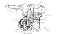
トルクリミッタ50は、図4及び5に示すように、スリーブ52、第2回転部材としての内輪53、弾性部材としてのコイルバネ54、第1回転部材としての外輪51を備える。第2回転部材としての内輪53は、モータ41のモータシャフト41aの軸方向において、モータ41と第1回転部材としての外輪51との間に配設されている。
As shown in FIGS. 4 and 5, the
スリーブ52は、D字状部52aと鍔部52bとをもち、回転軸中心に孔52cが形成される。D字状部52aは回転軸軸に直交する面での断面形状がD字状になっている部分である。鍔部52bはD字状部52aのモータシャフト41aのモータ41側にて外輪51に当接し、外輪51のモータシャフト41a基部方向への移動を規制する部材である。孔52cはモータシャフト41aが相対回転不能に挿通される。モータシャフト41aは断面の一部が凹み、孔52cの断面形状もモータシャフト41aの断面とほぼ同じ形状になっているため、スリーブ52はモータシャフト41aに対して相対回転不能に組み合わされている。
The
内輪53は回転軸中心にスリーブ52のD字状部52aが軽圧入可能な凹部53aが設けられており、スリーブ52を介してモータ41のモータシャフト41aに一体回転可能に配設されている。コイルバネ54はその径が外周面53bよりも若干小さく、内輪53の外周面53bに弾性付勢される(従って、内輪53が他方の部材に相当する)。コイルバネ54が内輪53の外周面53bに締着される程度としては本実施形態におけるトルクリミッタ50遮断すべきトルクの大きさ(被駆動部材に印加される所定荷重の大きさ)によって決定する。つまり、トルクリミッタ50が遮断するトルクの大きさを大きくするにはコイルバネ54及び外周面53bの間の摩擦力が大きくなるようにコイルバネ54の拡径方向のバネ定数を大きくしたり、コイルバネ54の変形が大きくなるように、コイルバネ54の内径を小さくし、反対に、トルクリミッタ50が遮断するトルクの大きさを小さくするには、拡径方向のバネ定数を小さくしたり、コイルバネ54の変形が小さくなるように、コイルバネ54の内径を大きくする。コイルバネ54の両端部は拡径方向に向けて一部折り曲げられている係止部54aをもつ。外輪51は内輪53の外周面53bがコイルバネ54を介装した状態で緩設可能な内周面51cをもつ。内周面51cには係止部54aが係止可能な溝部51bが形成される。コイルバネ54は係止部54aが溝部51bに係止されることにより外輪51と一体回転する(従って、外輪51が一方の部材に相当する)。
The
外輪51には軸方向のモータ41から遠ざかる方向に隣接するようにウォーム51aが一体化されており、ウォーム51aの回転軸と同軸の回転軸にて一体回転する部材である。内輪53と外輪51とは直接接する状態(摺接状態)にて軸方向に隣接している。内輪53及び外輪51は、モータシャフト41aに対して相対移動可能になっている(図4〜6参照)。ウォーム51aの先端部511は先細形状になっており、モータ41から遠ざかる方向に移動する際にカバー131の内壁131aに当接することにより移動が制限されることで、内輪53からの抜けが防止されている。
A
ここで、歯車列441〜447の構成は、便座11及び便蓋12に対して、外力により閉じる方向に付勢された場合にトルクリミッタ50における外輪51(ウォーム51aが一体的に形成されている)がモータ41から離隔する方向に付勢されるように構成される(図6参照)。
Here, the
上記構成を有することから本実施形態の電動開閉装置は以下の作用効果を発揮する。まず、上記構造を有することにより、モータ41のモータシャフト41aの回転は、スリーブ52、トルクリミッタ50の内輪53を介してコイルバネ54、トルクリミッタの外輪51、外輪51に固定されたウォーム51aへと伝達される。ウォーム51aの回転は、ウォームホイール441を含む歯車列441〜447により減速されて便座シャフト46(又は便蓋シャフト47)に伝達され、被駆動部材としての便座11(又は便蓋12)が回動する。便座11を回動する便座シャフト46及び便蓋12を回動する便蓋シャフト47は、同軸であるため、省スペースに設けることが出来る。
Since it has the said structure, the electric switchgear of this embodiment exhibits the following effects. First, by having the above structure, the rotation of the
モータ41が便座11(又は便蓋12)を回転している際に、便座11(又は便蓋12)に大きな外力が加えられると、便座11(又は便蓋12)から歯車列441〜447、ウォーム51aを介して、トルクリミッタ50の外輪51に大きなトルク荷重がかかる。外輪51にかかるトルク荷重が制限されるべき大きさ以上の場合、トルクリミッタ50の外輪51に係止されたコイルバネ54と、コイルバネ54により弾性付勢される内輪53との間に滑りが生じる。よって、便座11(又は便蓋12)側からモータ41側への過大なトルク荷重の伝達が遮断されるので、モータ41や歯車列45の破損を防ぐことが出来る。トルクリミッタ50の内輪53とコイルバネ54との間に滑りが生じてトルクリミッタ50が作動するトルク荷重の大きさは、コイルバネ54が内輪53に及ぼす弾性力により調節出来、コイルバネ54の弾性係数、コイルバネの伸縮の長さ等を変化させることで任意に設定可能である。
When a large external force is applied to the toilet seat 11 (or the toilet lid 12) while the
なお、コイルバネ54は、両端に設けられた係止部54aによりトルクリミッタ50の外輪51に係止されるので、外輪51が内輪53に対して相対回転する際、一方の係止部54aに、コイルバネ54が伸ばされる方向に力がかかる場合は、同時に他方の係止部54aには、コイルバネ54が縮められる方向に同じ大きさの力がかかる。よって、いずれの回転方向へトルク荷重がかかっても、コイルバネ54が内輪53に及ぼす弾性力は変化しないので、トルクリミッタ50が作動するトルク荷重の大きさを一定とすることが出来る。また、トルクリミッタ50の外輪51側及び内輪53側のいずれから大きなトルク荷重が加えられた場合でも、トルクリミッタ50は同様に作動可能である。
Since the
ウォーム51aの回転中心が、挿通されたモータシャフト41aと一致し、ウォーム51aはモータシャフト41aに対して相対回転するので、ウォーム51aの回転中心がぶれるのを防ぐことが出来る。
Since the rotation center of the
また、便座11(又は便蓋12)に大きな外力が加えられると、歯車列441〜447を介してウォーム51aにはトルク荷重の他にスラスト荷重も加えられる。その場合に、ウォーム51aはモータ41のモータシャフト41aに摺動可能に挿通されており、内輪53とスリーブ52との間及びスリーブ52とモータシャフト41aの間も軽圧入により取り付けられているので、スラスト荷重によりウォーム51、トルクリミッタ50の外輪51、コイルバネ54、内輪53、スリーブ52は、モータシャフト41aに対し一体で軸方向に移動可能である。よって、モータシャフト41aの破損や、モータシャフト41aが軸方向に押されることによって生じるモータ40の破損を防ぐことが出来る。
When a large external force is applied to the toilet seat 11 (or the toilet lid 12), a thrust load is also applied to the
特に、便座11及び便蓋12に対しては閉方向に大きな力が加わることが想定され、歯車列441〜447の並び(数)を調節することにより、外力による閉方向への付勢によってはウォーム51aがモータ41から遠ざかる方向でのスラスト力が発生するようにしている。この場合に、ウォーム51aの先端部511がカバー131の内壁131aに押圧されて摩擦力が増大するが、内輪53との関係やスリーブ52との関係では押圧力は発生せず、内輪53及びスリーブ52に対する摩擦力の増大はない。そのために内輪53から外輪51へのトルクの伝達は、便座11(又は便蓋12)を閉じる方向に付勢することにより発生するスラスト力の大きさには影響されず、閉じる方向に付勢する力が歯車列441〜447を介してトルクリミッタ50に入力されたトルクの大きさに応じてトルクリミッタ50の内輪53及びコイルバネ54の間で滑りが発生することでトルクの伝達を制限することが可能になる。なお、便座11及び便蓋12を開方向に付勢する場合にはウォーム51aに印加されるスラスト力は閉じる場合と反対方向に働き、内輪53及び/又はスリーブ51と外輪51との間にスラスト力に応じた摩擦力が生じることになって、トルクリミッタ50を介して伝達されるトルクの割合が小さくなる。そのために、開く方向に付勢された場合において、トルクリミッタ50がトルクの伝達を制限するに至るトルクの大きさが、閉じる方向に付勢された場合と比べ大きくなる。しかしながら、トイレの使用形態を考慮すると、便座11及び便蓋12を閉じる場合に大きな力が印加されることは良くあっても、開ける場合に大きな力を印加することはあまり想定できない。従って、通常の使用状態においては本実施形態のような歯車列441〜447とトルクリミッタ50との相対位置関係を保つ。
In particular, it is assumed that a large force is applied to the
(変形態様)
以下に、本実施形態1の変形態様について説明する。以下の説明において、同じ構成要素については同じ符号を付している。また、関連する作用を発揮する構成要素についても同じ符号を付しているものもある。
(Modification)
Below, the deformation | transformation aspect of this Embodiment 1 is demonstrated. In the following description, the same components are denoted by the same reference numerals. Some components that exhibit related actions are also given the same reference numerals.
本変形態様の電動開閉装置15は、図7及び8に示すように、トルクリミッタ50の配置方向が軸方向において逆であること以外は上述した実施形態1の電動開閉装置14と同じ構成をもつ。つまり、第1回転部材としての外輪51は、モータ41のモータシャフト41aの軸方向において、モータ41と第2回転部材としての内輪53との間に配設されている。内輪53と外輪51との間における配置が逆になったことにより、スリーブ52におけるモータ41から遠ざかる側の先端部521がケース(図略)の内壁(図略)に当接し、その形状が先細形状になっている。そして、ウォーム51aの回転軸中心はモータ41のモータシャフト41aが貫通できる貫通孔になっており、先端部511aは先細形状になっている。また、本変形態様の電動開閉装置15は、図1における便器13の上方に配置したカバー131内の右方側に配設されており、実施形態1に対して開閉動作に対応する回転方向が逆転している。
As shown in FIGS. 7 and 8, the electric opening /
以上の構成を有することから本変形態様の電動開閉装置15は実施形態1の電動開閉装置14と同じ作用効果をもつ。同じ部分については説明を省略し、異なる部分を以下に説明する。
Since it has the above configuration, the
本変形態様の電動開閉装置15が適用されるトイレにおいて、便座11(又は便蓋12)を閉じる方向に外力によって付勢すると、歯車列441〜445を介してウォーム51aにモータ41が配設される方向へのスラスト力が印加される。その場合に、モータシャフト41aの軸受け411に先端部511aが押圧されることになり摩擦力が生じる。その場合に、外輪51は、内輪53との関係やスリーブ52との関係では押圧力は発生せず、内輪53及びスリーブ52に対する摩擦力の増大はない。そのために内輪53から外輪51へのトルクの伝達は、便座11(又は便蓋12)を閉じる方向に付勢することにより発生するスラスト力の大きさには影響されず、閉じる方向に付勢する力が歯車列441〜445を介してトルクリミッタ50に入力されたトルクの大きさに応じてトルクリミッタ50の内輪53及びコイルバネ54の間で滑りが発生することでトルクの伝達を制限することが可能になる。
In the toilet to which the electric opening /
(その他の形態)
上記実施形態では、トルクリミッタ50のコイルバネ54は外輪51に係止されていたが、コイルバネ54の両端に内向きの係止部を設け、内輪53に溝を設けて、コイルバネ54が内輪53に係止されるようにしても良い。この場合、コイルバネ54は外輪51の内周面に弾性付勢され、トルクリミッタ50作動時にはコイルバネ54と外輪51との間で相対回転する。この場合には内輪53が一方の部材に相当し、外輪51が他方の部材に相当する。
(Other forms)
In the above embodiment, the
また、上記実施形態では、トルクリミッタ50の外輪51がウォームギア51aに固定されていたが、内輪53(第1回転部材に相当)がウォームギア51aに固定され、外輪51(第2回転部材に相当)へモータシャフト41aの回転が伝達される構造にしても良い。この場合でも、コイルバネ54は、外輪51に係止される構造(この場合には外輪51が一方の部材に相当する)でも、内輪53に係止される構造(この場合には内輪53が一方の部材に相当する)でも良い。
In the above embodiment, the
1…電動便座装置
11…便座
12…便蓋
14、15…電動開閉装置
41…モータ
41a…モータシャフト(出力軸)
44…減速機構
441〜447…歯車列
50…トルクリミッタ
51…外輪(第1回転部材)
51a…ウォーム
51b…溝
53…内輪(第2回転部材)
54…コイルバネ(弾性部材)
54a…係止部
DESCRIPTION OF SYMBOLS 1 ... Electric
44 ... Deceleration mechanism 441-447 ...
51a ...
54 ... Coil spring (elastic member)
54a ... Locking portion
Claims (5)
該モータの出力により回転を行うウォームと、
該ウォームと噛合し前記ウォームの回転を減速して、便座及び便蓋の少なくとも1つの被駆動部材を開閉動作させる減速機構と、
前記被駆動部材に対して所定荷重以上の外力が作用した場合に、前記モータへのトルク伝達を遮断するトルクリミッタとを備えた電動便座装置において、
前記トルクリミッタは、
前記ウォームと一体回転する第1回転部材と、
前記モータの出力と一体回転を行う第2回転部材と
前記第1回転部材及び前記第2回転部材のうちの一方の部材に係止され、他方の部材の外周に締着され、前記所定荷重以上に外力が作用した場合には前記第1回転部材及び前記第2回転部材の間を相対回転させる弾性部材とを備え、
前記被駆動部材に対して閉方向の外力が作用した場合に、前記第1回転部材と前記第2回転部材とが離間することにより前記モータへのトルク伝達を遮断することを特徴とする電動便座装置。 A motor,
A worm that rotates according to the output of the motor;
A speed reduction mechanism that meshes with the worm and decelerates rotation of the worm to open and close at least one driven member of the toilet seat and toilet lid;
In an electric toilet seat device comprising a torque limiter for interrupting torque transmission to the motor when an external force of a predetermined load or more is applied to the driven member,
The torque limiter is
A first rotating member that rotates integrally with the worm;
A second rotating member that rotates integrally with the output of the motor, and is locked to one member of the first rotating member and the second rotating member, and is fastened to the outer periphery of the other member so that the predetermined load or more is reached. And an elastic member that relatively rotates between the first rotating member and the second rotating member when an external force is applied thereto,
When an external force in the closing direction is applied to the driven member, the first toilet member and the second rotary member are separated from each other to interrupt torque transmission to the motor. apparatus.
前記第2回転部材は、前記モータと前記第1回転部材との間に配設される請求項1に記載の電動便座装置。 When an external force greater than the load is applied, the speed reduction mechanism transmits the external force in a direction separating the worm from the motor,
The electric toilet seat device according to claim 1, wherein the second rotating member is disposed between the motor and the first rotating member.
前記第1回転部材は、前記モータと前記第2回転部材との間に配設される請求項1に記載の電動便座装置。 When an external force greater than the load is applied, the worm has the speed reduction mechanism that transmits the external force in a direction in which the motor is disposed;
The electric toilet seat device according to claim 1, wherein the first rotating member is disposed between the motor and the second rotating member.
Priority Applications (1)
| Application Number | Priority Date | Filing Date | Title |
|---|---|---|---|
| JP2008320766A JP5369661B2 (en) | 2008-12-17 | 2008-12-17 | Electric toilet seat device |
Applications Claiming Priority (1)
| Application Number | Priority Date | Filing Date | Title |
|---|---|---|---|
| JP2008320766A JP5369661B2 (en) | 2008-12-17 | 2008-12-17 | Electric toilet seat device |
Publications (2)
| Publication Number | Publication Date |
|---|---|
| JP2010142340A true JP2010142340A (en) | 2010-07-01 |
| JP5369661B2 JP5369661B2 (en) | 2013-12-18 |
Family
ID=42563400
Family Applications (1)
| Application Number | Title | Priority Date | Filing Date |
|---|---|---|---|
| JP2008320766A Active JP5369661B2 (en) | 2008-12-17 | 2008-12-17 | Electric toilet seat device |
Country Status (1)
| Country | Link |
|---|---|
| JP (1) | JP5369661B2 (en) |
Cited By (4)
| Publication number | Priority date | Publication date | Assignee | Title |
|---|---|---|---|---|
| JP2014212647A (en) * | 2013-04-19 | 2014-11-13 | 株式会社デンソー | Electric actuator |
| US10271697B2 (en) | 2017-01-19 | 2019-04-30 | Aisin Seiki Kabushiki Kaisha | Electric opening and closing device |
| CN113983137A (en) * | 2021-11-29 | 2022-01-28 | 深圳市博电电子技术有限公司 | Overload protection device, transmission device and closestool |
| CN114098498A (en) * | 2021-11-19 | 2022-03-01 | 深圳市博电电子技术有限公司 | Drive control device, toilet cover assembly and smart toilet |
Citations (3)
| Publication number | Priority date | Publication date | Assignee | Title |
|---|---|---|---|---|
| JPH0577481U (en) * | 1992-03-19 | 1993-10-22 | 株式会社三協精機製作所 | Speed governor such as toilet bowl |
| JPH08261294A (en) * | 1995-03-22 | 1996-10-08 | Fuji Photo Film Co Ltd | Driving force transmission structure |
| JP2006095120A (en) * | 2004-09-29 | 2006-04-13 | Toto Ltd | Electric opening and closing device of toilet seat and toilet cover |
-
2008
- 2008-12-17 JP JP2008320766A patent/JP5369661B2/en active Active
Patent Citations (3)
| Publication number | Priority date | Publication date | Assignee | Title |
|---|---|---|---|---|
| JPH0577481U (en) * | 1992-03-19 | 1993-10-22 | 株式会社三協精機製作所 | Speed governor such as toilet bowl |
| JPH08261294A (en) * | 1995-03-22 | 1996-10-08 | Fuji Photo Film Co Ltd | Driving force transmission structure |
| JP2006095120A (en) * | 2004-09-29 | 2006-04-13 | Toto Ltd | Electric opening and closing device of toilet seat and toilet cover |
Cited By (5)
| Publication number | Priority date | Publication date | Assignee | Title |
|---|---|---|---|---|
| JP2014212647A (en) * | 2013-04-19 | 2014-11-13 | 株式会社デンソー | Electric actuator |
| US9190884B2 (en) | 2013-04-19 | 2015-11-17 | Denso Corporation | Electric actuator |
| US10271697B2 (en) | 2017-01-19 | 2019-04-30 | Aisin Seiki Kabushiki Kaisha | Electric opening and closing device |
| CN114098498A (en) * | 2021-11-19 | 2022-03-01 | 深圳市博电电子技术有限公司 | Drive control device, toilet cover assembly and smart toilet |
| CN113983137A (en) * | 2021-11-29 | 2022-01-28 | 深圳市博电电子技术有限公司 | Overload protection device, transmission device and closestool |
Also Published As
| Publication number | Publication date |
|---|---|
| JP5369661B2 (en) | 2013-12-18 |
Similar Documents
| Publication | Publication Date | Title |
|---|---|---|
| JP6196331B2 (en) | Free type two-way clutch using coil spring | |
| JP5369661B2 (en) | Electric toilet seat device | |
| JP2016216973A (en) | Resistance generating device | |
| CN112739509A (en) | Improved hair cutting unit for a shaving device | |
| JP5131054B2 (en) | Elastic shaft coupling and electric power steering device | |
| JP4816474B2 (en) | Clutch device | |
| JP5532702B2 (en) | Electric toilet seat device | |
| JP5941876B2 (en) | Free type bidirectional clutch | |
| US6932205B2 (en) | Clutch | |
| JP2005337333A (en) | Gear with torque limiter mechanism | |
| JP2018091459A (en) | Drive device | |
| JP2005207500A (en) | Automatic opening/closing device for vehicle | |
| JP2005110449A (en) | Electric motor with speed reduction mechanism | |
| JP2007139029A (en) | Electric actuator | |
| JP4857215B2 (en) | Driving force forward / reverse switching device | |
| JP3925270B2 (en) | Motor drive device | |
| JP2010098889A (en) | Electric motor | |
| JP2001289265A (en) | Cluth and motor | |
| JP2007309417A (en) | Operating device for transmission | |
| JP4816467B2 (en) | Clutch device | |
| JP2015158238A (en) | Simple free type bidirectional clutch | |
| JP2016516160A (en) | Transmission drive unit and drive device for comfort comprising transmission drive unit | |
| JP4718810B2 (en) | Actuator | |
| JP5046045B2 (en) | Self-locking clutch | |
| JP2007285326A (en) | Two-way clutch unit |
Legal Events
| Date | Code | Title | Description |
|---|---|---|---|
| A621 | Written request for application examination |
Free format text: JAPANESE INTERMEDIATE CODE: A621 Effective date: 20111121 |
|
| A977 | Report on retrieval |
Free format text: JAPANESE INTERMEDIATE CODE: A971007 Effective date: 20130117 |
|
| A131 | Notification of reasons for refusal |
Free format text: JAPANESE INTERMEDIATE CODE: A131 Effective date: 20130122 |
|
| A521 | Request for written amendment filed |
Free format text: JAPANESE INTERMEDIATE CODE: A523 Effective date: 20130306 |
|
| TRDD | Decision of grant or rejection written | ||
| A01 | Written decision to grant a patent or to grant a registration (utility model) |
Free format text: JAPANESE INTERMEDIATE CODE: A01 Effective date: 20130820 |
|
| A61 | First payment of annual fees (during grant procedure) |
Free format text: JAPANESE INTERMEDIATE CODE: A61 Effective date: 20130902 |
|
| R151 | Written notification of patent or utility model registration |
Ref document number: 5369661 Country of ref document: JP Free format text: JAPANESE INTERMEDIATE CODE: R151 |
|
| S533 | Written request for registration of change of name |
Free format text: JAPANESE INTERMEDIATE CODE: R313533 |
|
| R350 | Written notification of registration of transfer |
Free format text: JAPANESE INTERMEDIATE CODE: R350 |
|
| S111 | Request for change of ownership or part of ownership |
Free format text: JAPANESE INTERMEDIATE CODE: R313113 |
|
| R350 | Written notification of registration of transfer |
Free format text: JAPANESE INTERMEDIATE CODE: R350 |