JP2010142299A - Method of manufacturing absorbent article - Google Patents
Method of manufacturing absorbent article Download PDFInfo
- Publication number
- JP2010142299A JP2010142299A JP2008320120A JP2008320120A JP2010142299A JP 2010142299 A JP2010142299 A JP 2010142299A JP 2008320120 A JP2008320120 A JP 2008320120A JP 2008320120 A JP2008320120 A JP 2008320120A JP 2010142299 A JP2010142299 A JP 2010142299A
- Authority
- JP
- Japan
- Prior art keywords
- absorbent body
- water
- absorbent
- sheet
- absorbent article
- Prior art date
- Legal status (The legal status is an assumption and is not a legal conclusion. Google has not performed a legal analysis and makes no representation as to the accuracy of the status listed.)
- Granted
Links
Images
Landscapes
- Absorbent Articles And Supports Therefor (AREA)
Abstract
【課題】エンボス加工によって表面シートと吸収体とを一体化するときの表面シート等の破れや切れを抑え、そこに付与される凹部の成形性に優れた吸収性物品の製造方法を提供する。
【解決手段】パルプ積繊体6を有する吸収体8に表面シート12を付与し、エンボス加工13を施して前記表面シートと前記吸収体とを一体化し凹部を形成する工程を有する吸収性物品の製造方法であって、前記表面シートの付与前及び/又は付与後に、前記吸収体に水撒布し、その水撒布部分9に対して、搬送されてくる前記表面シート側から前記吸収体に向けてエンボス加工を施す吸収性物品の製造方法を提供する。
【選択図】図1An object of the present invention is to provide a method for manufacturing an absorbent article that suppresses tearing or cutting of a surface sheet or the like when a surface sheet and an absorbent body are integrated by embossing, and is excellent in moldability of a concave portion imparted thereto.
An absorbent article having a step of applying a topsheet 12 to an absorbent body 8 having a pulp fiber 6 and embossing 13 to form a concave portion by integrating the topsheet and the absorbent body. In the production method, before and / or after the application of the topsheet, the absorbent body is water-spread, and the water-spread portion 9 is transported toward the absorbent body from the transported topsheet side. A method for producing an absorbent article to be embossed is provided.
[Selection] Figure 1
Description
本発明は、使い捨ておむつ、生理用ナプキン、失禁パッド等の吸収性物品の製造方法に関する。 The present invention relates to a method for producing absorbent articles such as disposable diapers, sanitary napkins, and incontinence pads.
一般に、生理用ナプキンやパンティーライナー等の吸収性物品は、パルプ繊維や吸水性ポリマーを混在させて積繊した吸収体の上下面を表面シートおよび裏面シートで被覆した後、所定長さに切断して製造される。このような吸収性物品を高速に安定して製造するため、各工程に関して、いろいろな提案がなされている。 In general, an absorbent article such as a sanitary napkin or panty liner is coated with a top sheet and a back sheet after covering the upper and lower surfaces of an absorbent body mixed with pulp fibers and a water-absorbing polymer, and then cut into a predetermined length. Manufactured. In order to manufacture such an absorbent article stably at high speed, various proposals have been made for each process.
一方、最近、吸収性物品には、使用時の液漏れの防止や吸収体の形状保持のために、肌当接面に表面シート上からエンボス加工が施されることがあり、通常、このエンボス加工は外周面に所定パターンの凹凸部を形成したパターンロールによってなされる場合が多い。このエンボス加工により溝状の凹部を形成することが多いが、このような機能性の構造部の形成に関して、その製造効率や製造品質、設計自由度を高めるため種々の対策が講じられている。例えば、横(幅)方向エンボスの接触長さと縦(長手)方向エンボスの接触長さの差を規定することで、各エンボス部分の加圧差を少なくして、表面シートの破れや浮きを防止したもの(特許文献1参照)、エンボスに高圧搾部と低圧搾部を形成し、表面シートの浮きや切れを生じることなく形成するようにしたもの(特許文献2参照)が知られている。 On the other hand, recently, an absorbent article may be embossed on the skin contact surface from the top sheet in order to prevent liquid leakage during use and to maintain the shape of the absorbent body. The processing is often performed by a pattern roll having a predetermined pattern of irregularities formed on the outer peripheral surface. Groove-shaped recesses are often formed by this embossing, but various measures have been taken with respect to the formation of such functional structures in order to increase manufacturing efficiency, manufacturing quality, and design freedom. For example, by defining the difference between the contact length of the embossing in the horizontal (width) direction and the length of the embossing in the longitudinal (longitudinal) direction, the pressure difference between the embossed parts was reduced, preventing the topsheet from being torn or lifted. A thing (refer patent document 2) which formed a high pressing part and a low pressing part in embossing, and formed it without generating a float and a cut of a surface sheet is known.
吸収性物品、特に生理用ナプキンにおいては、上述のように、物品の形態を安定化したり、経血等の漏れを防止する機能を付与したりすることに鑑み、表面シートと吸収体との積層領域にエンボス加工を施し、部材間を接合する溝状の凹部を成形することが行われている。
本発明は、エンボス加工によって表面シートと吸収体とを一体化するときの表面シート等の破れや切れを抑え、そこに付与される凹部の成形性に優れた吸収性物品の製造方法を提供することに関する。
In the absorbent article, especially sanitary napkin, as described above, in view of stabilizing the form of the article or providing the function of preventing leakage of menstrual blood and the like, the laminate of the topsheet and the absorbent body Embossing is performed on the region to form a groove-like recess for joining the members.
The present invention provides a method for manufacturing an absorbent article that suppresses tearing or cutting of a surface sheet or the like when the surface sheet and the absorbent body are integrated by embossing, and is excellent in the formability of a concave portion imparted thereto. About that.
本発明は、パルプ積繊体を有する吸収体に表面シートを付与し、エンボス加工を施して前記表面シートと前記吸収体とを一体化し凹部を形成する工程を有する吸収性物品の製造方法であって、前記表面シートの付与前及び/又は付与後に、前記吸収体に水撒布し、その水撒布部分に対して、前記表面シート側から前記吸収体に向けてエンボス加工を施す吸収性物品の製造方法を提供する。 The present invention is a method for producing an absorbent article, which includes a step of applying a surface sheet to an absorbent body having a pulp pile fiber body and embossing to integrate the surface sheet and the absorbent body to form a recess. Then, before and / or after the application of the topsheet, water absorbent is applied to the absorbent body, and the absorbent article is embossed from the topsheet side toward the absorbent body on the water sprayed portion. Provide a method.
本発明の製造方法によれば、エンボス加工によって表面シートと吸収体とを一体化するときの表面シート等の破れや切れを抑えながら表面シートと吸収体との一体化を確実に行い、また、そこに付与される凹部の成形性に優れる。 According to the manufacturing method of the present invention, the surface sheet and the absorbent body are reliably integrated while suppressing breakage and breakage of the surface sheet and the like when the surface sheet and the absorbent body are integrated by embossing, It is excellent in the moldability of the recessed part provided there.
以下、本発明の好ましい実施態様について、添付の図面に基づいて詳細に説明する。
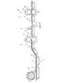
図1は、本発明の吸収性物品の製造方法の好ましい実施態様(実施態様1)に用いられる吸収性物品の製造設備10を概略的に示した全体側面図である。吸収性物品の製造設備10は、帯状のコアラップ材3を搬送する搬送装置1、コアラップ材3にパルプ繊維および吸水性ポリマーを供給する供給装置2、コアラップ材3に包まれたパルプ積繊体6を切断する切断機7、吸収体8に水を撒布する水撒布装置9、吸収体8に表面シート12を合流させる表面シート付与装置11、そして表面シート12と吸収体8にエンボス加工を施すエンボス加工装置13を有する。
Hereinafter, preferred embodiments of the present invention will be described in detail with reference to the accompanying drawings.
FIG. 1 is an overall side view schematically showing an absorbent
まず帯状のコアラップ材3が搬送装置1により送られ、この上面に供給装置2からパルプ繊維および吸水性ポリマーの混合体4が所定形状でかつ間欠に配置される。そして、搬送装置1の下流側へ送られた混合体4は、ロール5によりMD方向両側部を上面側へ折り畳まれたコアラップ材3に包まれ、帯状のパルプ積繊体6とされる。なお、ロール5は上記混合体4をコアラップ材3で包む折り畳み工程の直前に備えられており、これにより混合体4が動いたり蛇行したりしないように固定もしくは保持することができる。
First, the strip-shaped core wrap material 3 is sent by the transport device 1, and the
コアラップ材3に包まれたパルプ積繊体6は後続の切断機7に送られ、所定長さに前記コアラップ材とともに切断されて吸収体8となる。続いて吸収体8は水撒布装置9の下へと搬送され、ここで吸収体8に霧状の水が撒布される。この状態で表面シート付与装置11へ送られ、ここで吸収体8の表面に表面シート12が積層される。このとき必要により表面シートと吸収体との間に他の機能性のシートや部材を配設するようにしてもよい。表面シート12を付与された吸収体8はエンボス加工装置13へ送られ、所定のエンボスパターンを有するパターンロール14及びアンビルロール15によってエンボス加工が行われる。その後、液不透過性の裏面シート(図示せず)を帯状の表面シート12の反対側に積層し、ヒートロール(図示せず)により周縁シールを行う。さらに、これを所定の外形に切り出す切断機(図示せず)で加工して所望の吸収性物品として取り出される。必要によりサイドシート等の別の機能性の部材を組み込んだり、また裏面シートの外側に粘着剤等を塗付したりしてもよい。
The pulp pile 6 wrapped in the core wrap material 3 is sent to a subsequent cutting machine 7 and cut into a predetermined length together with the core wrap material to become an
上記の中でも本発明の特有の作用として、水撒布による表面シートと吸収体との接合性ないし凹部の賦形性の良化が挙げられる(凹部及びこれを構成する溝部の実施形態、並びにその成形加工の実施態様については、図2〜4に基づき後述する。)。その作用機序は断定的ではないが、一般にパルプ等の繊維体等は水素結合性の部材であり、水の存在により自己接着する性質が関与することが考えられる。また、パルプ繊維を有する吸収体への水撒布により吸収体の体積が減少し、表面シート等に対して結合力が高くなることも挙げられる。このように上記水撒布により、エンボス部及びエンボス部周辺のパルプ等の反発力が抑えられることや、表面シートと吸収体との接合性が高まることで、表面シートの浮きが抑えられ、製品品質の顕著な良化及び製造効率の大幅な向上をもたらす。 Among the above-mentioned effects, the characteristic action of the present invention includes improvement of the bonding property between the topsheet and the absorbent body by the water spraying or the shaping of the recesses (the embodiment of the recesses and the grooves forming the recesses, and the molding thereof). The processing embodiment will be described later with reference to FIGS. Although the mechanism of action is not definitive, generally, fiber bodies such as pulp are hydrogen-bonding members, and it is considered that the nature of self-adhesion due to the presence of water is involved. Moreover, the volume of an absorber reduces by the water-spreading to the absorber which has a pulp fiber, and the bond strength with respect to a surface sheet etc. becomes high. In this way, the above water-spreading cloth suppresses the repulsive force of the embossed part and the pulp around the embossed part, and the bondability between the surface sheet and the absorbent increases, thereby suppressing the float of the surface sheet, product quality Significantly improves the manufacturing efficiency.
本実施態様においては上述のように吸収体に水撒布を行うが、これにより以下のような利点(水撒布効果)がもたらされる。すなわち、吸収性物品に凹部を形成する吸収体部分に水撒布したときには、(1)水撒布部のパルプ繊維の反発力を低減させ表面シートとの結合力を高めることができる、(2)水撒布部のパルプ繊維が密になり吸収性物品の幅方向や前後端部への経血移行を抑制させ漏れ防止性を高めることができる、(3)水撒布部のパルプ繊維が密になり、吸収体の剛性が上がりヨレ防止性を高めることができるなどのことが挙げられる。 In this embodiment, the absorbent body is spread with water as described above, and this brings about the following advantages (water-spreading effect). That is, when water absorbent is applied to the absorbent part that forms the recess in the absorbent article, (1) the repulsive force of the pulp fibers in the water distributed part can be reduced and the binding force with the surface sheet can be increased. The pulp fibers in the lining portion become dense and can suppress the menstrual blood transfer to the width direction of the absorbent article and the front and rear end portions, and can improve leakage prevention. (3) The pulp fibers in the lining portion become dense, For example, the rigidity of the absorber can be increased and the anti-drafting property can be improved.
本実施態様における水撒布の量は特に限定されないが、例えば0.1g/製品1枚〜0.2g/製品1枚で撒布することが挙げられる。 Although the quantity of the water spreading in this embodiment is not specifically limited, For example, it is mentioned that 0.1g / one product-0.2g / one product is distributed.
上述の実施態様1では切断機7の下流側に水撒布装置9を設けて吸収体8に水撒布する例を示したが、これとは別の実施態様2として水撒布装置9を切断機7の上流側Bに設置し(実施態様2)、切断前のパルプ積繊体6に水撒布することも可能である。
In the first embodiment, the example in which the water spraying device 9 is provided on the downstream side of the cutting machine 7 and water spraying is performed on the
また、別の実施態様(実施態様3)として、吸収体を複数成形し、例えばそれを上層吸収体と下層吸収体として2層のものとし、さらには、それ以上の積層数にしたものとしてもよい。この場合、たとえば下層吸収体にまず水撒布して、これに上層吸収体を積層した後に、両方の吸収体に水撒布処理を行ってもよい。これにより吸収体の濡れ状態を良くして表面シートとの結合力をより高めることができる。また、両吸収体を2層に積層した後に水撒布することが挙げられる。この場合、水を撒布するのと反対側の層にある吸収体に水撒布処理がなされにくくなることになり、結合力は上下の吸収体にそれぞれ水撒布した場合と比べてやや弱くなるが、吸収体全体の柔らかさは増し、それだけ着用時のフィット感が良好となる。 Further, as another embodiment (embodiment 3), a plurality of absorbers may be formed, for example, two layers as an upper layer absorber and a lower layer absorber, and further, the number of layers may be increased. Good. In this case, for example, the lower layer absorber is first spread with water, and after the upper layer absorber is laminated thereon, both of the absorbers may be subjected to the water spread treatment. Thereby, the wet state of an absorber can be improved and the bond strength with a surface sheet can be raised more. In addition, it is possible to apply water absorbent after laminating both absorbers in two layers. In this case, it becomes difficult for the absorbent body on the opposite side of the water spraying to be subjected to the water spraying treatment, and the binding force is slightly weaker than when the upper and lower absorbent bodies are water sprayed, The softness of the entire absorbent body is increased, and the fit when worn is improved accordingly.
さらにまた別の実施態様(実施態様4)として、表面シート12を図1の反対側、つまり吸収体8の上方に配置し、水撒布装置9を表面シート付与装置11の後工程における矢印C位置に設け水撒布を行ってもよい。これにより表面シート12を配した吸収体8に対して表面シート12の側から水撒布を行うことができる。撒布された水は液透過性の表面シート12を通して吸収体8へ浸透し、これによってエンボス加工時にパルプ積繊体の反発力が抑制でき、表面シート12が吸収体8に確実に接合し、表面シートの剥がれや切れが効果的に防止される。
Furthermore, as another embodiment (embodiment 4), the
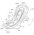
図2は本発明の製造方法により製造される吸収性物品の一実施形態としての生理用ナプキン20を表面シート側からみて模式的に示した一部切欠斜視図である。ここで上記製造工程(図1参照)における部材と共通するものは同じ符号及び名称により説明する。この生理用ナプキン20は平面視において略長方形状の吸収体8を表面シート12及び裏面シート17の間に介在して具備する。ただし、図1に示したものと異なり、吸収体8は下層吸収体8aと上層吸収体8b,8cとを積層した層構造のものとしている(図3参照)。そして、裏面シート17は長手方向前縁部、後縁部および両側縁部が吸収体8よりも張り出しており、この部分で表面シート12と裏面シート17とが場所によってサイドシート21とともにヒートシール、接着剤等によって周縁シール部11を形成するように接合されている。
FIG. 2 is a partially cutaway perspective view schematically showing a
本実施形態においては、上記上層吸収体8b,8cの部分が着用者の肌面側に隆起した部分をなし、それぞれ前方中高部18F及び後方中高部18Rを構成している。また、本実施形態の生理用ナプキン20には、その長手方向両側部に着用者の肌面側に立ち上がった立体ギャザーGをなす内部に糸ゴム22を有するサイドシート21が設けられている。ここで、表面シート12側が着用者の肌に接する面となり、裏面シート17側が下着に接する面となる。
In the present embodiment, the upper-
生理用ナプキン20は腹側に物品前方Fを配し、背側に物品後方Rを配して、着用者の排泄部の位置から臀部にかけて肌面に当てて着用する。生理用ナプキン20の前方位置の両側部には側方へ大きく耳状に張り出たサイドウィング部Swが形成されている。このサイドウィング部Swを含む裏面シート17の非肌当接面側(表面シート側と反対側)には粘着剤が付与されている。着用時にはサイドウィング部Swを下着のクロッチ部を挟み込むようにして折り畳み、下着のクロッチ部の両面に対してナプキンの裏面シートを接着させて固定する。このような構造及び着用形態の生理用ナプキンとすることにより下着への着用が容易かつ確実になるとともに、若干の液体等の漏れがあったときにも下着の汚れを効果的に防止することができる。
The
本実施形態の生理用ナプキン20には、図2のように、その表面(肌当接面)に凹部27が形成され、該凹部27はそれぞれ線状に形成された中央溝部27a、前方溝部27e、後方第1溝部27b、後方第2溝部27d、側方溝部27cで構成されている。中央溝27aは、前方中高部18Fと後方中高部18Rとの間に平面視において物品幅方向に延びる円弧状でありその中央が後方(R)に張り出す形状を有する。中央溝部27a、前方溝部27e、後方第1溝部27b、後方第2溝部27は、物品幅方向に延びる溝部分を有し、これらの溝部はまたパターンロール14の回転軸方向に延びる溝部分を有している。そして、この中央溝27aは側方溝部27c及び前方溝部27eと連続して前方中高部18Fを囲むように配設されている。他方、後方中高部18Rについてもこれを囲むように中央溝部27aが側方溝部27c及び後方第2溝部27dに連続して配設されている。さらに後方中高部18Rについては、側方溝部27cが物品後方Rにむけて分岐して上記後方第2溝部27dの外側をまわるように後方第1溝部27bに連続するようにされている。つまり、後方中高部18Rは二重の堀により取り囲まれたように、着用者の背側になる物品後方Rに2条の溝部が配設されている。これらの溝部がなす凹部27は、表面シート12から吸収体8に達して加熱圧搾し両者を一体化するエンボス加工によってなされる。
As shown in FIG. 2, the
本実施形態の生理用ナプキン20は、吸収体8の中高部18F,18Rによりその部分が肌当接面側に隆起し、起伏のある着用者の肌面にしっかりと当接し極めて良好なフィット感をもたらす。そして、上記凹部が表面シートと吸収体との部材間のずれや型崩れを抑えるとともに、経血等の排泄があたっときには防漏壁として機能し、高い漏れ防止性と着用時の形状安定性とを発揮する。また、中央溝部27aは上記形状安定性に加え、着用者の動きの状態によっては生理用ナプキンの中央付近で折り曲げ起点となり、あるいは個包装折り線として機能する。これにより、着用時に複雑な湾曲変形が生じたときや包装を解き使用を開始したときに肌面に良好に追従し快適な着用感を実現することができる。
The
本実施形態においては、上記前後に離間した前後の中高部18F,18Rをもつ吸収体を具備したナプキン20を製造するに際して、その両中高部の間となる部分(本実施形態では下層吸収体8a)に図1に示したような水撒布装置により水が撒布される。その後、表面シート12の側から吸収体8の水撒布部分に向けエンボス加工を施し、図2に示した溝部27a〜27eを付すよう加熱圧搾する。この圧搾加工には後述のような凸部を周面に有する加熱されたパターンロール14および平滑なアンビルロール15が用いられ、吸収体8の水撒布部分に表面シート12側から凹部27となる圧痕が残され両者が接合される。
In the present embodiment, when manufacturing the
本実施形態の生理用ナプキン20のように表面シート側と吸収体とを一体化する凹部27を付すときに、場合によりその確実な成形が難しいことがある。特に高速連続する場合や、上記のように凹部がパターンロール14の回転軸方向に延びる溝部分を有している場合や、上記のように隆起した複数の中高部を離間して有し、その谷間に凹部を成形するときには、加工品質を維持する上での困難性が顕著になる。
これに対し本発明の製造方法によれば、上記の水撒布効果により吸収性物品に的確かつ効果的に凹部を形成することができ、特に、上記実施形態にあるような長手方向に離間された中高部の谷間に深さのある中央溝部27aを付すようなときや、凹部にパターンロール14の回転軸方向に延びる溝部分を有しているときにも、高速連続生産を維持して安定した成形加工を実現することができる。
When the
On the other hand, according to the manufacturing method of the present invention, it is possible to accurately and effectively form the recesses in the absorbent article by the water-spreading effect, and in particular, the recesses are spaced apart in the longitudinal direction as in the above embodiment. Even when the
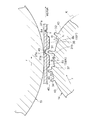
図3は図1に示したパターンロール14及びアンビルロール15の突き合わせ部分を拡大して示した説明図である。ただし、吸収体8は下層吸収体8a及び上層吸収体8b,8cからなるものとし、パターンロール14の部分的な軸直角断面を表面シート12及び吸収体8の断面とともに部分的に示したものである。同図においては表面シート、吸収体、及び溝部を、その成形前後を問わずに図2と同じ符号で表す。図3に部分的に示す生理用ナプキンの構成部材である吸収体8及び表面シート12の形態は、図2の生理用ナプキン20が長手方向に連続したと想定しその中心線に沿った断面に対応し、この製造途中の状態をナプキン20をCD方向に二分した位置のMD方向にむかう断面として示したものである。MD方向とは不織布等のシート材が製造時に流れる方向をいい、「Machine Direction」の略語である。流れ方向ともいう。CD方向とは上記MDに直交する方向であり、「Cross Direction」の略語である。
FIG. 3 is an explanatory view showing, in an enlarged manner, the butted portions of the
本実施態様においては、生理用ナプキン20の長手方向に離間した吸収体8の前方及び後方中高部の間で、生理用ナプキン20の幅方向に延びる円弧状の中央溝部27aが、工程上CD方向に延びる凹部27として成形される。そして、該パターンロール14及びアンビルロール15の回転(矢印r方向)に伴って所望のエンボス加工を施された表面シート12と吸収体8とがその長手方向であるMD方向に送られる。このようして、パターンロール14で凹部27を形成した後、裏面シートと積層し、周囲をシールして、長手方向の前後で所定の長さに裁断して、前述のような生理用ナプキン20が製造される。ただし、上記いずれかの工程及びその前後においてサイドシート21、糸ゴム22等を組み込むようにし、さらに裏面シート17の非肌当接面側の粘着剤等を適宜塗付する。
In this embodiment, the arc-shaped
本実施態様においては、中央溝部27aに対応するパターンロール14の凸部31に関し、その回転方向の前方及び/又は後方に隣接するパターンロール14の外周面(以下、これを「隣接外周面」という。)36,37は、吸収体8の中高部を構成する上層吸収体8b,8cの位置にきたときに、その部分の表面シート12との間にある程度の隙間Sを有するようにされている。すなわち、この隣接外周面36,37を、その回転方向の前方及び/又は後方の外周面(以下、「非隣接外周面」という。)43がなす外周面基線Kと間隔t1だけ位置Hで偏倚して面高さを異にし、パターンロールの外周面外方からみて、隣接外周面36,37が非隣接外周面43よりパターンロール内方に深くなるようにされている。このことは換言すると、前記パターンロール14において隣接外周面36,37が、このパターンロールの中心軸までの距離(ロール半径R1)として、非隣接外周面43ないしこれがなす外周面基線Kにおける前記中心軸までの距離(ロール半径R2)より小さくなるようにされたことを意味する(R1<R2)。なお、図2では模式的理解のためにパターンロールと表面シート及び吸収体からなる複合部材との間隔を実際よりもあけ、各凸部の先端部と複合部材の表面との隙間をより明瞭に表出している(図2では、実際の部材表面位置を示す表面シートの補助線(一点鎖線)1’との間隔S)。
In this embodiment, regarding the
本実施態様においては、凸部31〜34は圧搾に適した間隔をあけアンビルロール15に近接するようにされ、これらの高さ、つまりパターンロールの軸中心からの距離は等しくなるようにされている。本実施態様では、特に中央溝部27aを成形するロール凸部31の周方向前後の隣接外周面36,37をパターンロール外周面において陥没状態とし上述のように深さを持たせており、パターンロールが加熱されて上記隣接外周面が高温にされていても、これが吸収体部材の隆起した表面シートに実質的に当接しないようにし、特に表面シートに熱にデリケートな繊維や構造を適用したときにもダメージを与えないようにすることができる。上記隣接外周面が部材表面と「実質的に当接しない」とは全く当接しないことに加え、多少当接しても部材に機能上の損傷を与えないことを含む意味である。
In the present embodiment, the
パターンロール全体又は凸部31の温度は、加工を施す材料や生産速度によっても設定値は変更されるが、材料の融点以上の温度を与えることが好ましく、具体的には180℃〜220℃にすることが挙げられる。
アンビルロールの温度は、常温で行ってもよく、必要に応じてアンビルロールを加熱してもよい。その具体的な温度範囲は、例えば上記パターンロールと同じ温度範囲が挙げられ、具体的にパターンロールを120℃前後に設定し、アンビルロールを80℃前後に設定することが挙げられる。
The temperature of the entire pattern roll or the
The temperature of an anvil roll may be performed at normal temperature, and an anvil roll may be heated as needed. The specific temperature range is, for example, the same temperature range as the pattern roll, and specifically, the pattern roll is set to around 120 ° C. and the anvil roll is set to around 80 ° C.
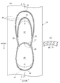
図4は図3に示したパターンロールの周面を平面上に展開した状態で示した部分的な平面図である。前述のように、生理用ナプキンにおける吸収体8の中高部18F,18R間の溝部27aはロール凸部31に対応し、前方溝部27eはロール凸部32に対応する。同様に、後方第2溝部27dは凸部33に対応し、後方第1溝部27bは凸部34に対応し、側方溝部27cは凸部35に対応する。この中で、離間した中高部の谷間に付される溝部27aに対応するパターンロールの凸部31はその根元部31bから先端部31a(図3参照)の長さが最もロール径方向に長い。なお、各凸部の先端には、図4(a)の凸部31の中央を拡大した(b)に示すように小突起45が形成されている。そして、上述のように、パターンロールの凸部の周方向における前後にある隣接外周面36,37は非隣接外周面43と位置Hでその面高さを異にし、ロール外方からみて隣接外周面が一段階深くなるようにされている。
FIG. 4 is a partial plan view showing a state in which the peripheral surface of the pattern roll shown in FIG. 3 is developed on a plane. As described above, the
本発明の製造方法により加工される部材は、通常この種の物品に用いられる材料を適宜選択して採用することができる。例えば、表面シートは、液透過性であり肌への当りのソフトな材料からなることが好ましい。例えばコットン等の天然繊維を材料とする不織布や、各種合成繊維に親水化処理を施したものを材料とする不織布を用いることができる。裏面シートは液不透過性や難透過性のフィルムや不織布で構成されるシート材からなることが好ましい。裏面シートは必要に応じて水蒸気の透過性のものであってもよい。具体的に十分な水蒸気透過性を得るために、炭酸カルシウム等のフィラーからなる微粉を分散させたポリエチレン等の合成樹脂製のフィルムを延伸し、微細な孔をあけた多孔質フィルムを用いることが好ましい。サイドシートとしては、不織布、フィルムシート、紙等が挙げられる。防漏性の観点からは、サイドシートを液不透過性又は難透過性である疎水性不織布、防漏性のフィルムシート等により形成することが好ましい。上記シートは一枚でもよいし、さらに機能性のシート等と組み合わせて2枚以上のものとしてもよい。吸収体の形成材料としては、通常吸収性物品に用いられるものを用いることができる。具体的には例えば、繊維集合体又はこれと高分子吸水ポリマーとを併用させたもの等を用いることができる。繊維集合体を構成する繊維としては、パルプ繊維等の親水性天然繊維や、合成繊維(好ましくは親水化処理を施したもの)等を用いることができる。 For the member processed by the manufacturing method of the present invention, a material usually used for this type of article can be appropriately selected and employed. For example, the top sheet is preferably made of a material that is liquid permeable and soft against the skin. For example, a non-woven fabric made of natural fibers such as cotton or a non-woven fabric made of various synthetic fibers subjected to hydrophilic treatment can be used. The back sheet is preferably made of a sheet material composed of a liquid-impermeable or hardly-permeable film or a nonwoven fabric. The back sheet may be water vapor permeable as required. Specifically, in order to obtain sufficient water vapor permeability, a film made of synthetic resin such as polyethylene in which fine powder made of a filler such as calcium carbonate is dispersed is stretched and a porous film having fine holes is used. preferable. Examples of the side sheet include a nonwoven fabric, a film sheet, and paper. From the viewpoint of leakage prevention, it is preferable that the side sheet is formed of a liquid non-permeable or hardly permeable hydrophobic nonwoven fabric, a leak-proof film sheet, or the like. One sheet may be used, or two or more sheets may be combined with a functional sheet. As the material for forming the absorber, those usually used for absorbent articles can be used. Specifically, for example, a fiber aggregate or a combination of this and a polymer water-absorbing polymer can be used. As the fibers constituting the fiber assembly, hydrophilic natural fibers such as pulp fibers, synthetic fibers (preferably subjected to hydrophilic treatment), and the like can be used.
上述の実施形態ではいずれも物品長手方向の前後に離間した中高部を持つ吸収体を具備した生理用ナプキンの製造を例示したが、本発明はこのような形態のものに限定されるものではない。また、パンティーライナー、使い捨ておむつ、尿とりパッド等といった他種の吸収性物品の製造にも同様に適用可能である。例えば、上記実施形態と同様に幅方向に延びる凹部を有するが、吸収体の中高部は有しないタイプの生理用ナプキンが挙げられる。その場合は、パターンロールの凸部に隣接した隣接外周面をその前後の非隣接外周面より深く偏倚したものとしなくてもよい。また、上記実施形態ではパルプ繊維がコアラップ材に被覆されてそれぞれ成形された吸収体を2層に積層した構造として示したが、堆積させる型として中高部に対応する凹部を設けたものを利用し、断面凸状の積繊体を形成して、その全体を1枚のコアラップ材で被覆したものを用いてもよい。 In the above-described embodiments, the manufacture of the sanitary napkin including the absorbent body having the middle and high parts spaced apart in the longitudinal direction of the article is exemplified, but the present invention is not limited to such a form. . The present invention is also applicable to the production of other types of absorbent articles such as panty liners, disposable diapers, urine pads, and the like. For example, the sanitary napkin of the type which has the recessed part extended in the width direction similarly to the said embodiment, but does not have the middle-high part of an absorber is mentioned. In that case, the adjacent outer peripheral surface adjacent to the convex part of the pattern roll may not be biased deeper than the front and rear non-adjacent outer peripheral surfaces. Moreover, in the said embodiment, although it showed as a structure which laminated | stacked the absorber by which the pulp fiber was coat | covered with the core wrap material and laminated | stacked in two layers, as what is used as the type | mold to deposit, what provided the recessed part corresponding to a mid-high part was utilized. Alternatively, a laminated fiber having a convex cross section may be formed and the whole coated with a single core wrap material.
1 搬送装置
2 供給装置
3 コアラップ材
4 混合体
6 パルプ積繊体
7 切断機
8 吸収体
8a 下層吸収体
8b,8c 上層吸収体
18F 前方中高部
18R 後方中高部
9 水撒布装置
10 吸収性物品の製造設備
11 表面シート付与装置
12 表面シート
13 エンボス加工装置
14 パターンロール
15 アンビルロール
17 裏面シート
20 生理用ナプキン
27 凹部
27a,27b,27c,27d,27e 溝部
31,32,33,34,35 凸部
36,37 隣接外周面
43 非隣接外周面
45 小突起
DESCRIPTION OF SYMBOLS 1
Claims (4)
前記表面シートの付与前及び/又は付与後に、前記吸収体に水撒布し、その水撒布部分に対して、前記表面シート側から前記吸収体に向けてエンボス加工を施す吸収性物品の製造方法。 A method for producing an absorbent article having a step of providing a topsheet to an absorbent body having a pulp pile, embossing and integrating the topsheet and the absorbent body to form a recess,
The manufacturing method of the absorbent article which water-spreads to the said absorber before and / or after the provision of the said surface sheet, and embosses the water-spreading part toward the said absorber from the said surface sheet side.
Priority Applications (1)
| Application Number | Priority Date | Filing Date | Title |
|---|---|---|---|
| JP2008320120A JP5297785B2 (en) | 2008-12-16 | 2008-12-16 | Method for manufacturing absorbent article |
Applications Claiming Priority (1)
| Application Number | Priority Date | Filing Date | Title |
|---|---|---|---|
| JP2008320120A JP5297785B2 (en) | 2008-12-16 | 2008-12-16 | Method for manufacturing absorbent article |
Publications (2)
| Publication Number | Publication Date |
|---|---|
| JP2010142299A true JP2010142299A (en) | 2010-07-01 |
| JP5297785B2 JP5297785B2 (en) | 2013-09-25 |
Family
ID=42563361
Family Applications (1)
| Application Number | Title | Priority Date | Filing Date |
|---|---|---|---|
| JP2008320120A Expired - Fee Related JP5297785B2 (en) | 2008-12-16 | 2008-12-16 | Method for manufacturing absorbent article |
Country Status (1)
| Country | Link |
|---|---|
| JP (1) | JP5297785B2 (en) |
Cited By (6)
| Publication number | Priority date | Publication date | Assignee | Title |
|---|---|---|---|---|
| WO2013077074A1 (en) * | 2011-11-25 | 2013-05-30 | ユニ・チャーム株式会社 | Absorptive article and manufacturing method therefor |
| WO2015076239A1 (en) * | 2013-11-20 | 2015-05-28 | 花王株式会社 | Absorbent article |
| WO2016121797A1 (en) * | 2015-01-29 | 2016-08-04 | 山田 菊夫 | Laid pulp sheet and process for producing laid pulp sheet |
| JP2017196276A (en) * | 2016-04-28 | 2017-11-02 | 王子ホールディングス株式会社 | Absorbent article manufacturing method and manufacturing apparatus |
| JP2017196278A (en) * | 2016-04-28 | 2017-11-02 | 王子ホールディングス株式会社 | Absorbent article manufacturing method and manufacturing apparatus |
| WO2019106731A1 (en) * | 2017-11-28 | 2019-06-06 | 花王株式会社 | Method for producing absorber and method for producing absorbent article |
Citations (3)
| Publication number | Priority date | Publication date | Assignee | Title |
|---|---|---|---|---|
| JPH1119119A (en) * | 1997-07-01 | 1999-01-26 | Kao Corp | Absorbent for absorbent article and method for producing the same |
| JP2006239162A (en) * | 2005-03-03 | 2006-09-14 | Kao Corp | Absorbent articles |
| JP2008125602A (en) * | 2006-11-17 | 2008-06-05 | Kao Corp | Absorber and absorbent article using the same |
-
2008
- 2008-12-16 JP JP2008320120A patent/JP5297785B2/en not_active Expired - Fee Related
Patent Citations (3)
| Publication number | Priority date | Publication date | Assignee | Title |
|---|---|---|---|---|
| JPH1119119A (en) * | 1997-07-01 | 1999-01-26 | Kao Corp | Absorbent for absorbent article and method for producing the same |
| JP2006239162A (en) * | 2005-03-03 | 2006-09-14 | Kao Corp | Absorbent articles |
| JP2008125602A (en) * | 2006-11-17 | 2008-06-05 | Kao Corp | Absorber and absorbent article using the same |
Cited By (17)
| Publication number | Priority date | Publication date | Assignee | Title |
|---|---|---|---|---|
| TWI620552B (en) * | 2011-11-25 | 2018-04-11 | Uni Charm Corp | Absorbent article and method of manufacturing same |
| JP2013111127A (en) * | 2011-11-25 | 2013-06-10 | Unicharm Corp | Absorbent article and method for manufacturing the same |
| CN103906489A (en) * | 2011-11-25 | 2014-07-02 | 尤妮佳股份有限公司 | Absorptive article and manufacturing method therefor |
| CN103906489B (en) * | 2011-11-25 | 2015-10-21 | 尤妮佳股份有限公司 | Absorbent article and its manufacturing method |
| WO2013077074A1 (en) * | 2011-11-25 | 2013-05-30 | ユニ・チャーム株式会社 | Absorptive article and manufacturing method therefor |
| WO2015076239A1 (en) * | 2013-11-20 | 2015-05-28 | 花王株式会社 | Absorbent article |
| JP2015097715A (en) * | 2013-11-20 | 2015-05-28 | 花王株式会社 | Absorbent article |
| WO2016121797A1 (en) * | 2015-01-29 | 2016-08-04 | 山田 菊夫 | Laid pulp sheet and process for producing laid pulp sheet |
| JPWO2016121797A1 (en) * | 2015-01-29 | 2017-08-24 | 山田 菊夫 | Pulp pile fiber sheet and method for producing pulp pile fiber sheet |
| JP2017196276A (en) * | 2016-04-28 | 2017-11-02 | 王子ホールディングス株式会社 | Absorbent article manufacturing method and manufacturing apparatus |
| JP2017196278A (en) * | 2016-04-28 | 2017-11-02 | 王子ホールディングス株式会社 | Absorbent article manufacturing method and manufacturing apparatus |
| WO2019106731A1 (en) * | 2017-11-28 | 2019-06-06 | 花王株式会社 | Method for producing absorber and method for producing absorbent article |
| JPWO2019106731A1 (en) * | 2017-11-28 | 2019-12-12 | 花王株式会社 | Method for manufacturing absorbent body and method for manufacturing absorbent article |
| GB2575216A (en) * | 2017-11-28 | 2020-01-01 | Kao Corp | Method for producing absorber and method for producing absorbent article |
| RU2750537C1 (en) * | 2017-11-28 | 2021-06-29 | Као Корпорейшн | Method for manufacturing the absorbent component and method for manufacturing the absorbent product |
| US11207218B2 (en) | 2017-11-28 | 2021-12-28 | Kao Corporation | Method for producing absorber and method for producing absorbent article |
| GB2575216B (en) * | 2017-11-28 | 2022-08-24 | Kao Corp | Method for producing absorber and method for producing absorbent article |
Also Published As
| Publication number | Publication date |
|---|---|
| JP5297785B2 (en) | 2013-09-25 |
Similar Documents
| Publication | Publication Date | Title |
|---|---|---|
| JP4739942B2 (en) | Absorbent articles | |
| JP5841774B2 (en) | Absorbent package | |
| KR101968380B1 (en) | Absorbent article | |
| TWI603722B (en) | Absorbent article | |
| JP5380095B2 (en) | Absorbent package | |
| WO2022024591A1 (en) | Individually-packaged absorbent article and method for manufacturing individually-packaged absorbent article | |
| JP2006325639A (en) | Absorbent articles | |
| KR20100022490A (en) | Laminated body of sheet-like member | |
| JP5297785B2 (en) | Method for manufacturing absorbent article | |
| JP5996448B2 (en) | Absorbent article manufacturing apparatus and absorbent article manufacturing method | |
| JP6047323B2 (en) | Disposable diaper and method for producing the same | |
| JP5962079B2 (en) | Disposable diaper and method for manufacturing disposable diaper | |
| JP6147326B1 (en) | Method for manufacturing absorbent article | |
| WO2017169391A1 (en) | Absorbent article | |
| JP4953735B2 (en) | Absorbent article and manufacturing method thereof | |
| JP4953734B2 (en) | Absorbent article and manufacturing method thereof | |
| JP5919331B2 (en) | Method for manufacturing absorbent article | |
| JP6591279B2 (en) | Absorbent article, packaging structure for absorbent article, and method for manufacturing absorbent article packaging structure | |
| WO2014208364A1 (en) | Absorbent article with wings and manufacturing method therefor | |
| JP6308646B2 (en) | Absorbent articles | |
| JP7448424B2 (en) | post-processing tape | |
| WO2014104158A1 (en) | Absorbent article | |
| JP5186331B2 (en) | Absorbent articles | |
| CN120201979A (en) | Individually packaged absorbent article | |
| JP2024143329A (en) | Individually-packaged absorbent article |
Legal Events
| Date | Code | Title | Description |
|---|---|---|---|
| A621 | Written request for application examination |
Free format text: JAPANESE INTERMEDIATE CODE: A621 Effective date: 20110914 |
|
| A977 | Report on retrieval |
Free format text: JAPANESE INTERMEDIATE CODE: A971007 Effective date: 20120924 |
|
| A131 | Notification of reasons for refusal |
Free format text: JAPANESE INTERMEDIATE CODE: A131 Effective date: 20121009 |
|
| A521 | Written amendment |
Free format text: JAPANESE INTERMEDIATE CODE: A821 Effective date: 20121210 Free format text: JAPANESE INTERMEDIATE CODE: A523 Effective date: 20121210 |
|
| RD03 | Notification of appointment of power of attorney |
Free format text: JAPANESE INTERMEDIATE CODE: A7423 Effective date: 20121210 |
|
| TRDD | Decision of grant or rejection written | ||
| A01 | Written decision to grant a patent or to grant a registration (utility model) |
Free format text: JAPANESE INTERMEDIATE CODE: A01 Effective date: 20130521 |
|
| A61 | First payment of annual fees (during grant procedure) |
Free format text: JAPANESE INTERMEDIATE CODE: A61 Effective date: 20130617 |
|
| R151 | Written notification of patent or utility model registration |
Ref document number: 5297785 Country of ref document: JP Free format text: JAPANESE INTERMEDIATE CODE: R151 |
|
| R250 | Receipt of annual fees |
Free format text: JAPANESE INTERMEDIATE CODE: R250 |
|
| R250 | Receipt of annual fees |
Free format text: JAPANESE INTERMEDIATE CODE: R250 |
|
| R250 | Receipt of annual fees |
Free format text: JAPANESE INTERMEDIATE CODE: R250 |
|
| R250 | Receipt of annual fees |
Free format text: JAPANESE INTERMEDIATE CODE: R250 |
|
| LAPS | Cancellation because of no payment of annual fees |