JP2010142008A - Vibration preventing device - Google Patents
Vibration preventing device Download PDFInfo
- Publication number
- JP2010142008A JP2010142008A JP2008315249A JP2008315249A JP2010142008A JP 2010142008 A JP2010142008 A JP 2010142008A JP 2008315249 A JP2008315249 A JP 2008315249A JP 2008315249 A JP2008315249 A JP 2008315249A JP 2010142008 A JP2010142008 A JP 2010142008A
- Authority
- JP
- Japan
- Prior art keywords
- wire
- stranded
- composite core
- vibration preventing
- core wire
- Prior art date
- Legal status (The legal status is an assumption and is not a legal conclusion. Google has not performed a legal analysis and makes no representation as to the accuracy of the status listed.)
- Pending
Links
Images


Landscapes
- Vibration Prevention Devices (AREA)
- Suspension Of Electric Lines Or Cables (AREA)
Abstract
Description
本発明は、架空送電線に取り付けられる振動防止装置に関する。 The present invention relates to a vibration preventing device attached to an overhead power transmission line.
一般に、鉄塔間に架線された架空送電線には、微風によって微風振動が発生している。この微風振動は、振動から生じる架空送電線の疲労による破断や架空送電線及び架空送電線が掛け渡される鉄塔等の金属類の摩耗や破損等を生じさせていた。そのため、架空送電線には、従来より、この微風振動を抑制させる振動防止装置として、電線ダンパが設けられている。 Generally, a slight wind vibration is generated by a slight wind on an overhead power transmission line connected between steel towers. This slight wind vibration has caused breakage due to fatigue of the overhead power transmission line resulting from vibration, wear and damage of the overhead power transmission line and metals such as a steel tower over which the overhead power transmission line is stretched. For this reason, the overhead power transmission line is conventionally provided with an electric wire damper as a vibration preventing device that suppresses this slight wind vibration.
電線ダンパは、通常、架空送電線を把持するクランプと、クランプに支持され、架空送電線と略平行に水平方向に延在する撚り線と、撚り線の両端部に偏心可能に固設される重錘と、を備えて構成されている。このように構成された電線ダンパは、撚り線の両端に設けられた重錘が微風振動により交互に上下方向に振り子運動を行う。そして、重錘が振り子運動を行うことにより撚り線が撚られ、架空送電線の振動エネルギーが撚り線の素線自体又は素線間の摩擦エネルギーに転換されて消散されていくように構成されている。 The electric wire damper is normally fixed to a clamp that holds the overhead power transmission line, a stranded wire that is supported by the clamp and extends in a horizontal direction substantially parallel to the overhead power transmission line, and eccentrically fixed to both ends of the stranded wire. And a weight. In the electric wire damper configured as described above, the weights provided at both ends of the stranded wire perform the pendulum motion alternately in the vertical direction by the slight wind vibration. And the strand is twisted by the pendulum movement of the weight, and the vibration energy of the overhead power transmission line is converted into the strand wire itself or the friction energy between the strands to be dissipated. Yes.
ところで、上述のように構成された電線ダンパは、電線ダンパを架空送電線に取り付けた場合、撚り線、及び重錘と撚り線との接合部に自重等から発生する応力が生じる。また、電線ダンパは、通常、鋼製の撚り線が用いられている。そのため、電線ダンパは、撚り線の振動疲労や腐食等による損傷減耗、及び重錘の重荷重等により撚り線が破断し、重錘が地上へ落下するおそれがあるという問題があった。 By the way, when the electric wire damper comprised as mentioned above attaches an electric wire damper to an aerial transmission line, the stress which generate | occur | produces from a self-weight etc. arises in the junction part of a stranded wire and a weight and a stranded wire. In addition, steel wire is usually used for the wire damper. For this reason, the wire damper has a problem that there is a risk that the stranded wire may be broken due to damage and wear due to vibration fatigue or corrosion of the stranded wire and a heavy load of the weight, and the weight may fall to the ground.
これに対しては、落下防止用のワイヤーロープを電線ダンパの電線把持部と重錘部とに取り付け、重錘の落下を防止する振動防止装置が開示されている(例えば、特許文献1参照)。
しかしながら、特許文献1に開示の振動防止装置は、落下防止用のワイヤーロープを電線把持部や重錘部に別途取り付ける必要があるため、電線把持部や重錘部にワイヤーロープの取り付け加工が必要となるという問題があった。 However, the vibration preventing device disclosed in Patent Document 1 requires a wire rope to be attached to the electric wire gripping portion or the weight portion because it is necessary to separately attach the wire rope for preventing the fall to the electric wire gripping portion or the weight portion. There was a problem of becoming.
本発明は、上記問題に鑑みなされたものであって、撚り線の破断を抑制すると共に、撚り線の破損を早期に発見可能にすることにより、重錘の落下を未然に防止可能な振動防止装置を提供することを目的とする。 The present invention has been made in view of the above-described problem, and prevents vibration of the weight by preventing breakage of the weight by suppressing breakage of the twisted wire and enabling early detection of breakage of the twisted wire. An object is to provide an apparatus.
(1) 本発明の振動防止装置は、架空電線を把持可能な電線把持部と、複数の線材により構成され、略中央部が前記電線把持部に固着される撚り線部と、前記撚り線部の両端に固設される重錘部と、を備え、前記撚り線部は、炭素系繊維材料を複合させて構成される複合芯線部と、前記複合芯線部の周りを捩るようにして配置される鋼線部と、を有する。 (1) The vibration preventing device of the present invention includes an electric wire gripping portion capable of gripping an overhead electric wire, a stranded wire portion that is configured by a plurality of wires, and whose substantially central portion is fixed to the electric wire gripping portion, and the stranded wire portion. Weight portions fixed to both ends of the wire, and the twisted wire portion is disposed so as to twist around the composite core wire portion and a composite core wire portion formed by combining carbon fiber materials. A steel wire portion.
(2) また、前記複合芯線部及び/又は前記重錘部には、前記撚り線部の損傷を報知する報知手段が設けられることが好ましい。 (2) Moreover, it is preferable that the said composite core wire part and / or the said weight part are provided with the alerting | reporting means which alert | reports the damage of the said strand wire part.
(3) また、前記複合芯線部には、損傷時における強度を補填する補填材料が埋設されることが好ましい。 (3) Moreover, it is preferable that the said composite core wire part is embed | buried with the filling material which supplements the intensity | strength at the time of damage.
(4) また、前記報知手段は、前記複合芯線部及び/又は前記重錘部に前記撚り線部の損傷時に視認可能に所定の塗料が塗布された視認部を設けることにより構成されることが好ましい。 (4) Moreover, the said notification means is comprised by providing the visual recognition part by which the predetermined coating material was apply | coated to the said composite core wire part and / or the said weight part so that visual recognition at the time of the damage of the said strand wire part was possible. preferable.
(5) また、前記補填材料は、マイクロカプセルに内包された接着材料であることが好ましい。 (5) Moreover, it is preferable that the said filling material is the adhesive material enclosed in the microcapsule.
本発明によれば、撚り線の破断を抑制すると共に、撚り線の破損を早期に発見可能にすることにより、重錘の落下を未然に防止可能な振動防止装置を提供することができる。 ADVANTAGE OF THE INVENTION According to this invention, while preventing the breakage of a strand wire and making it possible to discover the breakage of a strand wire at an early stage, it is possible to provide a vibration preventing device that can prevent the weight from falling.
以下、本発明を実施するための最良の形態について、図面を参照しながら説明する。 The best mode for carrying out the present invention will be described below with reference to the drawings.
図1は、本発明の実施形態に係る振動防止装置の外観構成を示す外観斜視図である。図2は、前記実施形態に係る振動防止装置の外観構成を示す分解斜視図である。図3は、図2に示す撚り線部のA−A断面を示すA−A断面図である。図4は、前記実施形態に係る振動防止装置の複合芯線部の軸方向における断面を示す断面図である。図5は、前記実施形態に係る振動防止装置の固設部に設けられる圧着スリーブ及び圧着スリーブに固設される重錘を示す外観斜視図である。図6は、図5に示す固着部に設けられる圧着スリーブのB−B断面を示すB−B断面図である。図7は、前記実施形態に係る振動防止装置の重錘の水平方向における一端部を示す部分拡大図である。 FIG. 1 is an external perspective view showing an external configuration of a vibration preventing apparatus according to an embodiment of the present invention. FIG. 2 is an exploded perspective view showing an external configuration of the vibration preventing apparatus according to the embodiment. 3 is a cross-sectional view taken along the line AA showing the AA cross section of the stranded wire portion shown in FIG. 2. FIG. 4 is a cross-sectional view showing a cross section in the axial direction of the composite core wire portion of the vibration preventing device according to the embodiment. FIG. 5 is an external perspective view showing a crimp sleeve provided at a fixed portion of the vibration preventing device according to the embodiment and a weight fixed to the crimp sleeve. 6 is a BB cross-sectional view showing a BB cross section of the pressure-bonding sleeve provided in the fixing portion shown in FIG. 5. FIG. 7 is a partial enlarged view showing one end portion of the weight of the vibration preventing device according to the embodiment in the horizontal direction.
本発明の実施形態に係る振動防止装置1は、地上に設置された鉄塔等の支持物(図示せず)に支持されて架設した架空送電線路において、鉄塔等の支持物に架線された架空送電線Wに取り付けられている。架空送電線Wは、鉄塔等の支持物に地上から20〜30mの高さで架線されている。 An anti-vibration device 1 according to an embodiment of the present invention is an aerial transmission line that is installed on a support (not shown) such as a steel tower installed on the ground, and is aerial transported over a support such as a steel tower. It is attached to the electric wire W. The overhead power transmission line W is wired to a support such as a steel tower at a height of 20 to 30 m from the ground.
まず、本実施形態に係る振動防止装置1の全体構成について説明する。
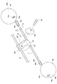
図1及び図2に示すように、振動防止装置1は、架空送電線Wを把持する電線把持部2と、電線把持部2に固着される撚り線部3と、撚り線部3の両端に固設される重錘4a,4bと、を備えて構成されている。
First, the overall configuration of the vibration preventing apparatus 1 according to the present embodiment will be described.
As shown in FIGS. 1 and 2, the vibration preventing device 1 includes an electric wire holding part 2 that holds the overhead power transmission line W, a stranded
電線把持部2は、架空送電線Wの外周面を一方側と他方側とから挟み込むようにして架空送電線Wを把持するように構成されている。具体的には、電線把持部2は、架空送電線Wの外周面の一方側に配置され、電線把持部2の外観を構成するクランプ20と、架空送電線Wの外周面の他方側に配置される押さえ金具21と、を有して構成されている。クランプ20と押さえ金具21とは、ボルト22により締結可能に形成されている。
The electric wire gripping portion 2 is configured to grip the overhead power transmission line W so as to sandwich the outer peripheral surface of the overhead power transmission line W from one side and the other side. Specifically, the electric wire gripping portion 2 is disposed on one side of the outer peripheral surface of the overhead power transmission line W, and is disposed on the other side of the outer peripheral surface of the overhead power transmission line W and the
クランプ20には、架空送電線Wと対向する側に架空送電線Wの一部と嵌合可能な第1嵌合溝20aが形成されている。また、押さえ金具21には、架空送電線Wと対向する側に架空送電線Wの一部と嵌合可能な第2嵌合溝21aが形成されている。
In the
電線把持部2は、架空送電線Wの外周面の一方側に架空送電線Wの一部を第1嵌合溝20aに嵌合させた状態でクランプ20を配置し、他方側に架空送電線Wの一部を第2嵌合溝21aに嵌合させた状態で押さえ金具21を配置させ、クランプ20と押さえ金具21とをボルト22により締結させることにより、架空送電線Wを把持するように形成されている。
The electric wire gripping part 2 arranges the
また、電線把持部2には、撚り線部3が固着される固着部23が設けられている。固着部23は、クランプ20の端部に設けられている。固着部23は、撚り線部3が架空送電線Wと略平行に延在するように撚り線部3を固着している。具体的には、固着部23には、撚り線部3を挿通可能な挿通孔24が設けられており、撚り線部3は挿通孔24に挿通された状態でクランプ20に固着されている。
Further, the wire gripping portion 2 is provided with a
図3に示すように、撚り線部3は、複数の線材から構成されている。具体的には、撚り線部3の軸心部に芯線として設けられる複合芯線30と、複合芯線30の外周面に複合芯線30を捩るように配置される複数の鋼線31と、を備えて構成されている。
As shown in FIG. 3, the
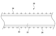
複合芯線30は、図4に示すように、芯線部32と、芯線部32を被覆する被覆部33と、を有して構成されている。芯線部32は、炭素繊維やガラス繊維等の繊維材料を繊維フィラメントとして用い、これを多数本束ねたり、ロープ状に撚り合わせたり、編組等にて断面円形状にしたものや、それらを繊維強化プラスチックとして成型加熱処理したものにより形成されている。本実施形態においては、芯線部32は、炭素繊維強化プラスチックにより形成されている。
As shown in FIG. 4, the
被覆部33は、合成樹脂により形成されている。合成樹脂としては、例えば、オレフィン系の樹脂が用いられる。オレフィン系の樹脂としては、エチレン、プロピレン、1−ブテン、2−ブテン、イソブテン、1−ペンテン、2−ペンテン、2−メチル−1−ブテン、3−メチル−1−ブテン、2−メチル−2−ブテン、1−ヘキセン、3−メチル−1−ペンテン、4−メチル−1−ペンテン、2−ヘキセン、シクロヘキセン、2,3−ジメチル−2−ブテン、2,3−ジメチル−1−ブテン、α−ピネン等の単量体を持つものや、それらの共重合体等が例示できる。
The covering
また、オレフィン系の樹脂は、成形品としての特性を損なわない範囲であれば、組成混和物として用いてもよい。また、上記のオレフィン系樹脂には、一般的にオレフィン系樹脂に使用される充填剤、酸化防止剤、分散剤、着色剤、耐候剤、難燃剤等の添加剤を必要に応じて使用することもできる。さらに、オレフィン系の樹脂は、例えば、耐候性を向上させるためにカーボンブラックを添加してもよい。 In addition, the olefin-based resin may be used as a composition mixture as long as the properties as a molded article are not impaired. In addition, additives such as fillers, antioxidants, dispersants, colorants, weathering agents, flame retardants and the like that are generally used for olefin resins should be used as necessary for the olefin resins. You can also. Furthermore, carbon black may be added to the olefin-based resin, for example, in order to improve weather resistance.
また、被覆部33には、外周面に接着材料としての接着剤が内包された複数のマイクロカプセル34が塗布されている。マイクロカプセル34に内包される接着剤は、複合芯線30が損傷したときに複合芯線30の強度を補填する補填材料を構成する。
A plurality of
複合芯線30は、マイクロカプセル34を被覆部33の外周面に塗布することにより、例えば、複合芯線30の損傷により複合芯線30が屈曲又は湾曲したときに、屈曲部又は湾曲部に塗布されたマイクロカプセル34が割裂し、内包された接着剤が流出することにより、複合芯線30の損傷部分に係る屈曲部又は湾曲部を硬化させ、損傷部分を補填するように構成されている。
For example, when the
マイクロカプセル34に内包される接着剤としては、合成系の接着剤が用いられ、例えば、アクリル樹脂系接着剤、α−オレフィン系接着剤、ウレタン樹脂系接着剤、セルロース系接着剤、エポキシ樹脂系接着剤、クロロブレンゴム系接着剤、シアノアクリレート系接着剤、シリコーン系接着剤、スチレン−ブタジエンゴム系ラテックス接着剤、プリスチレン樹脂溶剤系接着剤等が例示できる。
As the adhesive contained in the
また、芯線部32と被覆部33とは、ホットメルト接着剤により密着されている。具体的には、芯線部32にホットメルト接着剤を塗布し、その上に被覆部33が形成されている。ホットメルト接着剤としては、芯線部32と被覆部33とを接着可能なものであればよく、一般に市販されているものであってもよい。ホットメルト接着材のベースポリマーとしては、例えば、エチレン−酢酸ビニルコポリマー(EVA)、ポリエチレン、アタクチックポリプロピレン(APP)、エチレン−アクリル酸エチルコポリマー(EEA)、ポリアミド、ポリエステル、などがあり、特殊なものとしてポリカーボネート、ポリビニルエーテル、ポリビニルアルコール、ポリウレタン、セルロース系等が例示できる。
Moreover, the
図5及び図6に示すように、撚り線部3の両端部には、圧着スリーブ35a,35bが設けられている。圧着スリーブ35a,35bは、一端側が封止された略円筒状に形成されている。圧着スリーブ35a,35bは、開口する他端側から撚り線部3の一端部に挿入され、撚り線部3の一端部で圧着されている。また、圧着スリーブ35a,35bは、端部に雄ネジ部36a,36bが形成されている。雄ネジ部36a,36bには、雄ネジが切られている。なお、圧着スリーブ35a,35bは、アルミニウム等の軟性の金属により形成されている。
As shown in FIGS. 5 and 6, crimp
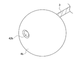
重錘4a,4bは、略球形状に形成されている。重錘4a,4bには、中心部から偏心した位置に固設孔40a,40bが形成されている。固設孔40a,40bには、雌ネジ部41a,41bが設けられており、雌ネジ部41a,41bには、圧着スリーブ35a,35bに設けられる雄ネジ部36a,36bの雄ネジと螺合可能な雌ネジが切られている。重錘4a,4bは、圧着スリーブ35a,35bの雄ネジ部36a,36bに雌ネジ部41a,41bを螺合させることにより、撚り線部3の両端それぞれに固設される。
The
また、図7に示すように、重錘4a,4bには、重錘4a,4bの固設状態における水平方向端部に、報知手段としての視認部42a,42bが設けられている。視認部42a,42bには、蛍光塗料が塗布されている。視認部42a,42bは、振動防止装置1が通常の状態においては地上から視認不可能であるが、例えば、撚り線部3が金属疲労や腐食等により損傷し、屈曲又は湾曲した場合等、重錘4a,4bが撚り線部3により垂れ下がった状態になった場合に視認可能に設けられている。
As shown in FIG. 7, the
前述した構成を有する本実施形態の振動防止装置1によれば、以下に示す各効果が奏される。 According to the vibration preventing apparatus 1 of the present embodiment having the above-described configuration, the following effects are exhibited.
本実施形態に係る振動防止装置1は、炭素繊維強化プラスチックにより形成された複合芯線30を軸心に配置した撚り線部3を備えて構成されている。そのため、撚り線部3の耐摩耗性、耐熱性、耐酸性及び耐引張力を向上させることが可能になる。これにより、例えば、撚り線部3を構成する他の鋼線31が金属疲労等を起こし破損した場合においても、複合芯線30の存在により、その両端に固設された重錘4a,4bが直ちに地面に落下することを防止することが可能になる。
The vibration preventing device 1 according to the present embodiment is configured to include a stranded
また、本実施形態に係る振動防止装置1は、複合芯線30が炭素繊維強化プラスチックにより形成された芯線部32と、芯線部32を被覆する被覆部33と、を有して形成されている。また、被覆部33は、オレフィン系の樹脂を用いて構成されている。そのため、例えば、芯線部32が破損した場合においても被覆部33の存在により、直ちに重錘4a,4bが地面に落下することを防止することが可能になる。つまり、複合芯線30の耐トラッキング性を向上させることが可能になる。これにより、振動防止装置1は、電線落下防止機能を長期間安定して維持することが可能になる。
Moreover, the vibration preventing apparatus 1 according to the present embodiment is formed so that the
また、本実施形態に係る振動防止装置1は、被覆部33の外表面に接着剤が内装されたマイクロカプセル34が塗布されている。そのため、例えば、複合芯線30の損傷により複合芯線30が屈曲又は湾曲したときに、屈曲部又は湾曲部に塗布されたマイクロカプセル34が割裂し、内包された接着剤が流出することにより、複合芯線30の損傷部分に係る屈曲部又は湾曲部を硬化させ、損傷部分を補填することが可能になる。これにより、振動防止装置1は、電線落下防止機能を長期間安定して維持することが可能になる。
Further, in the vibration preventing device 1 according to the present embodiment, the
また、本実施形態に係る振動防止装置1は、重錘4a,4bの固設状態における水平方向端部に、報知手段としての視認部42a,42bが設けられている。視認部42a,42bは、振動防止装置1が通常の設置状態においては地上から視認不可能であるが、例えば、撚り線部3が金属疲労や腐食等により屈曲又は湾曲した場合、例えば、重錘が撚り線部3により垂れ下がった状態になった場合等に視認可能に設けられている。そのため、撚り線部3が破損した場合に、直ちに撚り線部3の破損を認識することが可能になる。つまり、撚り線部3の破損を早期に発見可能にすることにより、重錘4a,4bの落下を未然に防止することが可能なる。
Moreover, the vibration preventing apparatus 1 according to the present embodiment is provided with
また、本実施形態に係る振動防止装置1は、重錘4a,4bを圧着スリーブ44a,44bに設けられる雄ネジ部45a,45bに螺合させた状態で撚り線部3に固設されている。そのため、重錘4a,4bは、撚り線部3に対して着脱が可能な状態で取り付けられている。これにより、振動防止装置1は、メンテナンスが容易になる。
Further, the vibration preventing device 1 according to the present embodiment is fixed to the
なお、本発明は、上記実施形態に何ら限定されることなく、本発明の技術的範囲はこれらに限定されるものではない。例えば、本実施形態においては、撚り線部3の破損を報知する報知手段として、重錘4a,4bの端部に設けられる視認部42a,42bに蛍光塗料を塗布し、撚り線部3の破損により重錘4a,4bが垂れ下がり、地上から蛍光塗料が視認されることにより撚り線部3の破損を報知する構成としたが、本発明においてはこれに限定されるものではない。例えば、視認部42a,42bにLED等の発光部材を配置させる構成であってもよく、シール等を貼り付ける構成としてもよい。報知手段は、撚り線部3が破損することで重錘4a,4bが垂れ下がり、これにより地上から視認部42a,42bが視認可能なものであればよい。
In addition, this invention is not limited to the said embodiment at all, and the technical scope of this invention is not limited to these. For example, in the present embodiment, as a reporting means for notifying the breakage of the stranded
また、例えば、撚り線部3に蛍光塗料を内包させたマイクロカプセルを塗布させておき、撚り線部3が破損して屈曲又は湾曲することにより屈曲部又は湾曲部近傍のマイクロカプセルから蛍光塗料が放出され、これを報知手段とする構成としてもよい。
In addition, for example, a microcapsule in which a fluorescent paint is encapsulated is applied to the stranded
また、例えば、被覆部33に蛍光塗料を塗布させておき、被覆部33の周りに設けられる複数の鋼線31が金属疲労や腐食等により破損した場合に被覆部33の蛍光塗料を露出可能にする構成としてもよい。
Further, for example, a fluorescent paint is applied to the covering
また、本実施形態においては、マイクロカプセル34は、被覆部33の外表面に塗布する構成としたが、本発明においてはこれに限定されない。例えば、マイクロカプセル34は、被覆部33に混入させ、被覆部33の内部に内装させる構成であってもよい。
In the present embodiment, the
1 振動防止装置
2 電線把持部
3 撚り線部
4a、4b 重錘
20 クランプ
21 押さえ金具
30 複合芯線
31 鋼線
32 芯線部
33 被覆部
34 マイクロカプセル
40a,40b 固設部
41a,41b 雌ネジ部
42a,42b 視認部
W 架空送電線(架空電線)
DESCRIPTION OF SYMBOLS 1 Vibration prevention apparatus 2 Electric
Claims (5)
複数の線材により構成され、略中央部が前記電線把持部に固着される撚り線部と、
前記撚り線部の両端に固設される重錘部と、を備え、
前記撚り線部は、
炭素系繊維材料を複合させて構成される複合芯線部と、
前記複合芯線部の周りを捩るようにして配置される鋼線部と、を有する振動防止装置。 An electric wire gripper capable of gripping an overhead electric wire;
Consists of a plurality of wire rods, and a stranded wire portion whose substantially central portion is fixed to the wire gripping portion;
A weight portion fixed to both ends of the stranded wire portion, and
The stranded portion is
A composite core wire portion formed by combining carbon fiber materials;
And a steel wire portion disposed so as to twist around the composite core wire portion.
Priority Applications (1)
| Application Number | Priority Date | Filing Date | Title |
|---|---|---|---|
| JP2008315249A JP2010142008A (en) | 2008-12-11 | 2008-12-11 | Vibration preventing device |
Applications Claiming Priority (1)
| Application Number | Priority Date | Filing Date | Title |
|---|---|---|---|
| JP2008315249A JP2010142008A (en) | 2008-12-11 | 2008-12-11 | Vibration preventing device |
Publications (1)
| Publication Number | Publication Date |
|---|---|
| JP2010142008A true JP2010142008A (en) | 2010-06-24 |
Family
ID=42351624
Family Applications (1)
| Application Number | Title | Priority Date | Filing Date |
|---|---|---|---|
| JP2008315249A Pending JP2010142008A (en) | 2008-12-11 | 2008-12-11 | Vibration preventing device |
Country Status (1)
| Country | Link |
|---|---|
| JP (1) | JP2010142008A (en) |
Cited By (6)
| Publication number | Priority date | Publication date | Assignee | Title |
|---|---|---|---|---|
| JP2014003829A (en) * | 2012-06-19 | 2014-01-09 | Furukawa Electric Power Systems Co Ltd | Double torsional damper |
| CN105024302A (en) * | 2015-06-09 | 2015-11-04 | 云南电网有限责任公司曲靖供电局 | A carbon fiber plate single-conductive-wire hooking clamping tool for 110kV live-wire work |
| CN108963934A (en) * | 2018-09-28 | 2018-12-07 | 江苏天南电力器材有限公司 | A kind of conducting wire Pre-Cutter-Type Anti-Vibration Hammer |
| CN111682492A (en) * | 2020-06-11 | 2020-09-18 | 安徽省含山县兴建铸造厂 | Damper with hammerhead capable of being hung and weighted and mounting method thereof |
| CN111725732A (en) * | 2020-06-04 | 2020-09-29 | 安徽博晟亿电力科技有限公司 | Device capable of adjusting gravity center of damper and adjusting method thereof |
| CN113964769A (en) * | 2021-11-05 | 2022-01-21 | 安徽威龙电力器材有限公司 | High-altitude wind pressure resistance damper and mounting method thereof |
-
2008
- 2008-12-11 JP JP2008315249A patent/JP2010142008A/en active Pending
Cited By (10)
| Publication number | Priority date | Publication date | Assignee | Title |
|---|---|---|---|---|
| JP2014003829A (en) * | 2012-06-19 | 2014-01-09 | Furukawa Electric Power Systems Co Ltd | Double torsional damper |
| CN105024302A (en) * | 2015-06-09 | 2015-11-04 | 云南电网有限责任公司曲靖供电局 | A carbon fiber plate single-conductive-wire hooking clamping tool for 110kV live-wire work |
| CN105024302B (en) * | 2015-06-09 | 2018-09-28 | 云南电网有限责任公司曲靖供电局 | 110kV livewire work carbon fiber board single conductor hook fixture |
| CN108963934A (en) * | 2018-09-28 | 2018-12-07 | 江苏天南电力器材有限公司 | A kind of conducting wire Pre-Cutter-Type Anti-Vibration Hammer |
| WO2020062323A1 (en) * | 2018-09-28 | 2020-04-02 | 江苏天南电力器材有限公司 | Wire pre-twisted damper |
| CN111725732A (en) * | 2020-06-04 | 2020-09-29 | 安徽博晟亿电力科技有限公司 | Device capable of adjusting gravity center of damper and adjusting method thereof |
| CN111725732B (en) * | 2020-06-04 | 2021-08-27 | 安徽博晟亿电力科技有限公司 | Device capable of adjusting gravity center of damper and adjusting method thereof |
| CN111682492A (en) * | 2020-06-11 | 2020-09-18 | 安徽省含山县兴建铸造厂 | Damper with hammerhead capable of being hung and weighted and mounting method thereof |
| CN113964769A (en) * | 2021-11-05 | 2022-01-21 | 安徽威龙电力器材有限公司 | High-altitude wind pressure resistance damper and mounting method thereof |
| CN113964769B (en) * | 2021-11-05 | 2023-03-10 | 安徽威龙电力器材有限公司 | High-altitude wind pressure resistance damper and mounting method thereof |
Similar Documents
| Publication | Publication Date | Title |
|---|---|---|
| JP2010142008A (en) | Vibration preventing device | |
| US3932697A (en) | Rope terminations and methods and apparatus for fabricating the same | |
| JP4092237B2 (en) | Fiber rope for rope | |
| KR101864456B1 (en) | Hybrid rope | |
| CN104762842A (en) | Rope for elevator, elevator and method | |
| FI3245331T3 (en) | A mooring member | |
| CA2955051C (en) | Synthetic rope termination | |
| CN205348583U (en) | External all alone ground tackle of prestressed concrete | |
| CN113678045A (en) | An overhead optical cable laying hardware and an overhead optical cable that can be laid using the same | |
| US7954410B2 (en) | Fast rope | |
| CN203782354U (en) | High-strength light-reflecting/light-emitting safety rope | |
| RU159131U1 (en) | CONNECTING SLEEVE OF RAILWAY ROLLING STOCK | |
| KR20190080330A (en) | Rope | |
| CN108035255B (en) | Carbon fiber stay cable system | |
| CN109305598B (en) | An OPLC construction traction device | |
| JP2008010374A (en) | lighting equipment | |
| JP7278485B2 (en) | Bundled suspension wire | |
| JP3144280U (en) | Off-limit indicator | |
| JP2008202151A (en) | Rope | |
| WO2020213041A1 (en) | Delineator having light guide rod, and guard cable | |
| CN208965303U (en) | A kind of polyethylene three stranded rope | |
| CN114016668A (en) | Anchoring structure of FRP (fiber reinforced Plastic) reinforcement cable and construction method thereof | |
| WO2017221454A1 (en) | Method for gripping optical fiber cable, and optical fiber cable gripping tool | |
| ITMI20071106A1 (en) | ROPE FOR ELECTRIC LINES | |
| JP2020504246A (en) | Spliced rope system |