JP2010141729A - Zoom adjustment system and camera - Google Patents
Zoom adjustment system and camera Download PDFInfo
- Publication number
- JP2010141729A JP2010141729A JP2008317518A JP2008317518A JP2010141729A JP 2010141729 A JP2010141729 A JP 2010141729A JP 2008317518 A JP2008317518 A JP 2008317518A JP 2008317518 A JP2008317518 A JP 2008317518A JP 2010141729 A JP2010141729 A JP 2010141729A
- Authority
- JP
- Japan
- Prior art keywords
- zoom adjustment
- magnification
- displacement
- zoom
- locus
- Prior art date
- Legal status (The legal status is an assumption and is not a legal conclusion. Google has not performed a legal analysis and makes no representation as to the accuracy of the status listed.)
- Pending
Links
- 230000003287 optical effect Effects 0.000 claims abstract description 80
- 238000006073 displacement reaction Methods 0.000 claims description 74
- 238000001514 detection method Methods 0.000 claims description 10
- 230000007423 decrease Effects 0.000 claims description 6
- 238000013459 approach Methods 0.000 claims description 5
- 238000000034 method Methods 0.000 description 35
- 238000010586 diagram Methods 0.000 description 2
- 238000003384 imaging method Methods 0.000 description 2
- 230000003111 delayed effect Effects 0.000 description 1
- 230000000694 effects Effects 0.000 description 1
- 239000000284 extract Substances 0.000 description 1
- 230000006870 function Effects 0.000 description 1
- 230000007704 transition Effects 0.000 description 1
Images
Classifications
-
- H—ELECTRICITY
- H04—ELECTRIC COMMUNICATION TECHNIQUE
- H04N—PICTORIAL COMMUNICATION, e.g. TELEVISION
- H04N23/00—Cameras or camera modules comprising electronic image sensors; Control thereof
- H04N23/60—Control of cameras or camera modules
- H04N23/69—Control of means for changing angle of the field of view, e.g. optical zoom objectives or electronic zooming
Landscapes
- Engineering & Computer Science (AREA)
- Multimedia (AREA)
- Signal Processing (AREA)
- Studio Devices (AREA)
- Camera Bodies And Camera Details Or Accessories (AREA)
- Indication In Cameras, And Counting Of Exposures (AREA)
Abstract
Description
本発明は、簡易な入力操作でカメラの撮影光学系の倍率を調整するズーム調整システムに関する。 The present invention relates to a zoom adjustment system that adjusts the magnification of a photographing optical system of a camera by a simple input operation.
従来のカメラでは、撮影光学系の焦点距離を調整することにより撮影する被写体像の倍率を調整することが可能である。近年のコンパクトカメラにはズーム調整ボタンが設けられ、ズーム調整ボタンを押下することにより倍率の調整が可能である。また、ズーム調整ボタンを押下し続けることにより、倍率の増加または減少への調整が継続される。 In a conventional camera, it is possible to adjust the magnification of a subject image to be photographed by adjusting the focal length of the photographing optical system. A recent compact camera is provided with a zoom adjustment button, and the magnification can be adjusted by pressing the zoom adjustment button. Further, by continuously pressing the zoom adjustment button, the adjustment to increase or decrease of the magnification is continued.
しかし、ズーム調整ボタンの押下停止が遅れると、調整された倍率が使用者の希望する倍率を超えることがある。このような場合、逆方向の倍率調整が必要であり、迅速に被写体像の倍率を調整することが困難だった。 However, if the stop of pressing the zoom adjustment button is delayed, the adjusted magnification may exceed the magnification desired by the user. In such a case, it is necessary to adjust the magnification in the reverse direction, and it is difficult to quickly adjust the magnification of the subject image.
また、近年では、デジタルカメラにタッチパネルモニタを設けることが提案されている。また、タッチパネルモニタへの入力パターンに応じて様々な機能を実行することが提案されており(特許文献1参照)、簡易な方法で操作コマンドを入力することが可能である。 In recent years, it has been proposed to provide a digital camera with a touch panel monitor. Further, it has been proposed to execute various functions according to an input pattern to the touch panel monitor (see Patent Document 1), and an operation command can be input by a simple method.
しかし、特許文献1に記載された発明を用いても、使用者の希望する倍率に迅速に且つ正確に調整することは、困難であった。
したがって、本発明では、簡易な入力操作により、迅速且つ正確に使用者の望む倍率に調整するズーム調整システムの提供を目的とする。 Accordingly, an object of the present invention is to provide a zoom adjustment system that adjusts a magnification desired by a user quickly and accurately by a simple input operation.
本発明のズーム調整システムは、入力面を有し入力面上の任意の位置への接触の有無および接触された位置である接触位置を検出するタッチパネルと、入力面への接触が維持されたまま接触位置が変位する場合に接触位置の変位の軌跡である変位軌跡を検出する軌跡検出部と、軌跡検出部により検出された変位軌跡に応じて撮影光学系の倍率を調整する光学ズーム調整部とを備えることを特徴としている。 The zoom adjustment system of the present invention has a touch panel that has an input surface and detects the presence / absence of contact with an arbitrary position on the input surface and the contact position that is the touched position, and the contact with the input surface is maintained A trajectory detection unit that detects a displacement trajectory that is a trajectory of displacement of the contact position when the contact position is displaced; an optical zoom adjustment unit that adjusts the magnification of the imaging optical system according to the displacement trajectory detected by the trajectory detection unit; It is characterized by having.
さらに、光学ズーム調整部は変位軌跡の大きさに応じて撮影光学系の倍率を調整することが好ましい。 Furthermore, it is preferable that the optical zoom adjustment unit adjusts the magnification of the photographing optical system in accordance with the size of the displacement locus.
また、光学ズーム調整部は入力面における第1の方向に沿った座標軸における変位軌跡の最大値と最小値とに基づいて変位軌跡の大きさを判別することが好ましい。 The optical zoom adjustment unit preferably determines the size of the displacement trajectory based on the maximum value and the minimum value of the displacement trajectory on the coordinate axis along the first direction on the input surface.
また、光学ズーム調整部は第1の方向に沿った座標軸における変位軌跡の最大値と最小値とに挟まれる幅を入力面の第1の方向に沿った幅に近づけるように撮影光学系の倍率を増加させることが好ましい。 Further, the optical zoom adjustment unit is configured so that the magnification between the maximum and minimum values of the displacement locus on the coordinate axis along the first direction approaches the width along the first direction of the input surface. Is preferably increased.
また、光学ズーム調整部は変位軌跡の大きさが大きくなる程撮影光学系の倍率を減少させることが好ましい。 Moreover, it is preferable that the optical zoom adjustment unit decreases the magnification of the photographing optical system as the size of the displacement trajectory increases.
また、光学ズーム調整部は変位軌跡の大きさが入力面内における所定の大きさを超える場合に撮影光学系の倍率を減少させることが好ましい。 Further, it is preferable that the optical zoom adjustment unit decreases the magnification of the photographing optical system when the size of the displacement locus exceeds a predetermined size in the input surface.
また、光学ズーム調整部は入力面内における変位軌跡が通過する領域に応じて撮影光学系の倍率を調整することが好ましい。 Further, it is preferable that the optical zoom adjustment unit adjusts the magnification of the photographing optical system in accordance with the region through which the displacement locus in the input surface passes.
また、入力面には第1の領域および第1の領域を内部に含む第2の領域が定められ、光学ズーム調整部は変位軌跡が第2の領域のみを通過する場合に撮影光学系の倍率を増加させ変位軌跡の通過する領域が第1の領域のみである場合には第1の領域外の第2の領域を通過する場合に比べて大きくなるように倍率を増加させることが好ましい。 In addition, the first area and the second area including the first area are defined on the input surface, and the optical zoom adjustment unit performs magnification of the photographing optical system when the displacement locus passes only the second area. When the region through which the displacement trajectory passes is only the first region, it is preferable to increase the magnification so as to be larger than when passing through the second region outside the first region.
また、入力面には第2の領域を内部に含む第3の領域が定められ、光学ズーム調整部は変位軌跡が通過する領域に第3の領域が含まれる場合に撮影光学系の倍率を減少させることが好ましい。 In addition, a third area including the second area is defined on the input surface, and the optical zoom adjustment unit reduces the magnification of the photographing optical system when the third area is included in the area through which the displacement locus passes. It is preferable to make it.
また、撮影光学系が調整可能な最大倍率に調整される場合には撮影光学系を通過して到達する撮像素子に撮影される画像の一部を抽出して拡大するデジタルズームの倍率を増加させるデジタルズーム調整部を備えることが好ましい。 Also, when the photographic optical system is adjusted to the maximum adjustable magnification, the digital zoom that increases the magnification of the digital zoom that extracts and enlarges a part of the image taken by the image sensor that passes through the photographic optical system It is preferable to provide an adjustment unit.
また、デジタルズーム調整部によりデジタルズームを実行開始するときに、入力面に任意の画像を表示可能なタッチパネルモニタであるタッチパネルにデジタルズームを開始することを表示する画像制御部を備えることが好ましい。 In addition, it is preferable to include an image control unit that displays that the digital zoom is started on a touch panel monitor that can display an arbitrary image on the input surface when the digital zoom adjustment unit starts executing the digital zoom.
また、タッチパネルは入力面に撮影可能な現在の光景であるリアルタイム画像を表示するタッチパネルモニタであることが好ましい。 The touch panel is preferably a touch panel monitor that displays a real-time image that is a current scene that can be photographed on the input surface.
本発明のカメラは、倍率を調整可能な撮影光学系と、入力面を有し入力面上の任意の位置への接触の有無および接触された位置である接触位置を検出するタッチパネルと、入力面への接触が維持されたまま接触位置が変位する場合に接触位置の変位の軌跡である変位軌跡を検出する軌跡検出部と、記軌跡検出部により検出された変位軌跡に応じて撮影光学系の倍率を調整する光学ズーム調整機構とを備えることを特徴としている。 A camera according to the present invention includes a photographing optical system capable of adjusting a magnification, a touch panel that has an input surface and detects whether or not an arbitrary position on the input surface is touched, and a touch position that is a touched position, and an input surface A trajectory detection unit that detects a displacement trajectory that is a trajectory of the displacement of the contact position when the contact position is displaced while maintaining contact with the image sensor, and a photographing optical system according to the displacement trajectory detected by the trajectory detection unit. And an optical zoom adjustment mechanism for adjusting the magnification.
本発明によれば、タッチパネルの接触位置を変位すると変位軌跡に応じて定められた倍率になるように撮影光学系を調整することが可能である。したがって、簡易な入力操作により、迅速且つ正確な倍率調整が可能となる。 According to the present invention, when the contact position of the touch panel is displaced, it is possible to adjust the photographing optical system so that a magnification determined according to the displacement locus is obtained. Therefore, quick and accurate magnification adjustment can be performed by a simple input operation.
以下、本発明の実施形態について図面を参照して説明する。 Embodiments of the present invention will be described below with reference to the drawings.
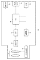
図1は、本発明の一実施形態を適用したズーム調整システムを有するデジタルカメラの内部構成を概略的に示すブロック図である。 FIG. 1 is a block diagram schematically showing an internal configuration of a digital camera having a zoom adjustment system to which an embodiment of the present invention is applied.
デジタルカメラ10は、撮影光学系11、撮像素子12、DSP(Digital Signal Processor)13、CPU14(軌跡検出部、デジタルズーム調整部、画像制御部)、タッチパネルモニタ15、光学系駆動回路16、光学系駆動機構17(光学ズーム調整部)などによって構成される。
The
撮影光学系11は、変倍レンズ群11zを含む複数のレンズにより構成される。変倍レンズ群11zを撮影光学系11の光軸方向に沿って変位させることにより、撮影光学系11の焦点距離が調整され、撮像素子12の受光面に到達する被写体像の倍率が調整される。なお、本実施形態では、第1〜第4の位置のいずれかに変倍レンズ群11zを変位させることが可能である。
The photographing
変倍レンズ群11zは、光学系駆動機構17によって支持される。また、光学系駆動機構17はモータ(図示せず)を有しており、モータによって変倍レンズ群11zは第1〜第4の位置のいずれかに変位させられる。
The variable
なお、変倍レンズ群11zの変位範囲の中で、撮影光学系11の焦点距離を最小にする位置が第1の位置に定められる。一方、撮影光学系11の焦点距離を最大にする位置が第4の位置に定められる。また、第1の位置から第4の位置までの間に、第2、第3の位置が順番に定められる。したがって、変倍レンズ群11zの位置が第1の位置に近づけられるほど被写体像の倍率は低く、変倍レンズ群11zの位置が第4の位置に近づけられるほど被写体像の倍率は高くなる。
Note that, within the displacement range of the
光学系駆動機構17は光学系駆動回路16に接続される。光学系駆動回路16によって光学系駆動機構17のモータは駆動される。光学系駆動回路16はCPU14に接続される。変倍レンズ群11zの変位はCPU14により制御される。
The optical
撮影光学系11は、撮像素子12に光学的に接続される。撮影光学系11を透過する被写体の光学像が撮像素子12の受光面に到達する。撮像素子12は、例えばCCDである。撮像素子12は、受光面において被写体の光学像を受光することにより、光学像に相当する画像信号を生成する。
The photographing
なお、撮影待機中には、タッチパネルモニタ15にリアルタイムの動画像を表示するために、動画像撮像用の駆動方法により1/30秒毎に1フレームの動画用画像信号が生成される。一方、撮影待機中にレリーズ動作を実行するコマンドが入力されたときには、静止画像撮影用の駆動方法により1フレームの静止画用画像信号が生成される。
During shooting standby, in order to display a real-time moving image on the
撮像素子12は、DSP13に接続される。生成したいずれの画像信号も、DSP13に送信される。DSP13では、受信した画像信号に対して所定の信号処理が施される。DSP13は、CPU14に接続される。所定の信号処理を施した画像信号は、CPU14に送信される。
The
動画用画像信号を受信するときには、CPU14からタッチパネルモニタ15のみに動画用画像信号が送信される。また、静止画用画像信号を受信するときには、CPU14からタッチパネルモニタ15および画像メモリ18に静止画用画像信号が送信される。
When receiving the moving image signal, the
タッチパネルモニタ15は、ディスプレイ(図1において図示せず)と検出部(図示せず)とによって構成される。CPU14から送信される画像信号はディスプレイに受信される。ディスプレイには、受信した画像信号に相当する画像が表示される。
The
なお、前述のように、動画用画像信号は1/30秒毎に生成され、タッチパネルモニタ15に送信される。したがって、1/30秒毎に表示させる画像を切替えることにより、撮影待機状態においてリアルタイムの被写体の動画像がタッチパネルモニタ15に表示される。
As described above, the moving image signal is generated every 1/30 seconds and transmitted to the
なお、使用者やタッチペンなどによるディスプレイの表面(入力面)への接触の有無および接触位置が検出部によって検出される。タッチパネルモニタ15のディスプレイに表示される画像とディスプレイへの接触位置などとに対応するコマンドが、予め定められる。後述するように、タッチパネルモニタ15はデジタルカメラ10のコマンド入力手段としても用いられる。
The presence or absence of contact with the surface (input surface) of the display by a user or a touch pen and the contact position are detected by the detection unit. Commands corresponding to the image displayed on the display of the touch panel monitor 15 and the position of contact with the display are determined in advance. As will be described later, the touch panel monitor 15 is also used as command input means of the
画像メモリ18には、受信した静止画用画像信号が格納される。なお、デジタルカメラ10は再生モードを有しており、再生モードに設定されているときに、格納された静止画用画像信号がCPU14を介してタッチパネルモニタ15に送信され、静止画像がタッチパネルモニタ15に表示される。
The
CPU14は、電源ボタン(図示せず)、レリーズボタン(図示せず)などを有する入力部19に接続される。入力部19へのコマンド入力に基づいて、CPU14はデジタルカメラ10の各部位を制御する。
The
前述のように、タッチパネルモニタ15もデジタルカメラ10へのコマンド入力機器に用いられる。ディスプレイへの接触とともに接触位置が検出されると、表示している画像および接触位置などがCPU14に通知される。CPU14により、表示している画像および接触位置などに対応付けられたコマンドが入力されたと判別される。CPU14は入力されたと判別したコマンドに基づいて、デジタルカメラ10の各部位を制御する。
As described above, the touch panel monitor 15 is also used as a command input device to the
次に、デジタルカメラ10の撮影待機中におけるズーム調整について説明する。前述のように、撮影待機中にはタッチパネルモニタ15にリアルタイムの動画像が表示される。撮影待機中にディスプレイの表面上に軌跡が描かれる、すなわち接触状態が維持されたまま接触位置が変位するときに、ズーム調整が実行される。
Next, zoom adjustment during shooting standby of the
指やタッチペンなどを用いたディスプレイへの接触位置が円を描くようにディスプレイ表面上を変位すると、描く円の大きさに応じて変倍レンズ群11zの位置が変位される。描く円が小さくなるほど、倍率が大きくなるように変倍レンズ群11zが変位される。
When the display surface using a finger, a touch pen, or the like is displaced on the display surface so as to draw a circle, the position of the
なお、円の大きさはどのような方法によって検知されてもよい。本実施形態では、接触位置の変位により通過する軌跡である変位軌跡の上下の幅、すなわちディスプレイの縦方向座標の最大値と最小値との差が円の大きさとして検出される。 Note that the size of the circle may be detected by any method. In the present embodiment, the vertical width of the displacement trajectory that is the trajectory that passes through the displacement of the contact position, that is, the difference between the maximum value and the minimum value of the vertical coordinate of the display is detected as the size of the circle.
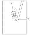
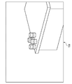
例えば、図2に示すように、変倍レンズ群11zが第2の位置にある場合にディスプレイ15dに表示される画像に対して変位軌跡が第1の大きさの円C1である場合に、変倍レンズ群11zは第3の位置に変位させられる。また、表示される画像に対して変位軌跡が第1の大きさより小さな第2の大きさの円C2である場合に、変倍レンズ群11zは第4の位置に変位させられる。また、変位軌跡がディスプレイの枠に近い部位を通過する場合には、変倍レンズ群11zは第1の位置に変位させられる。
For example, as shown in FIG. 2, when the displacement locus is a circle C1 of the first size with respect to the image displayed on the
変倍レンズ群11zが第3の位置に変位させられることにより撮像素子12に到達する被写体像は拡大される。なお、光学ズームが実行されるので、元の被写体像の中心部が拡大される。また、変位軌跡が描いた円に表示される画像がディスプレイ15d全範囲に表示されるようにリアルタイム画像が拡大される(図3参照)。
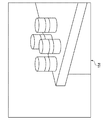
The subject image reaching the
また、変倍レンズ群11zが第4の位置に変位させられることにより、第3の位置に変位させられたときよりさらに高い倍率に拡大されたリアルタイム画像がディスプレイ15dに表示される(図4参照)。一方、変倍レンズ群11zが第1の位置に変位させられることにより、リアルタイム画像は縮小されて表示される(図5参照)。
In addition, when the variable
なお、デジタルズームを使うことにより、変倍レンズ群11zによる第4の位置に変位させたときよりも拡大させたリアルタイム画像をディスプレイに表示可能である。すなわち、動画用画像信号の一部を抽出して拡大する信号処理を施すことにより、リアルタイム画像を拡大可能である。
By using the digital zoom, it is possible to display on the display a real-time image that is enlarged as compared with the case where the
例えば、変倍レンズ群11zが第2の位置にある場合にディスプレイに表示される画像に対して第2の大きさの円よりさらに小さな第3の大きさの円を描くように指などを摺り動かすと、変倍レンズ群11zが第4の位置に変位させられ、さらにデジタルズームが実行される。
For example, when the
なお、デジタルズームを機能させる場合には、デジタルズームを実行する旨を伝えるメッセージがリアルタイム画像の上に重畳されて、表示される。デジタルズームを用いると表示されるリアルタイム動画像や撮影される静止画像の解像度が低下するので、使用者に注意を促すためである。 Note that when the digital zoom is functioned, a message indicating that the digital zoom is to be executed is superimposed on the real-time image and displayed. This is because when the digital zoom is used, the resolution of a real-time moving image to be displayed or a still image to be taken is lowered, so that the user is warned.
次に、CPU14によって行われるズーム調整制御を、図6〜図10のフローチャートを用いて説明する。ズーム調整制御は、撮影待機状態においてディスプレイ表面上に軌跡が描かれる、すなわち接触状態が継続されたまま接触位置が変位するときに実行される。
Next, zoom adjustment control performed by the
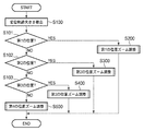
図6に示すように、ステップS100において、変位軌跡の大きさを検出する。前述のように、変位軌跡を構成する各点の中で、ディスプレイの縦方向座標の最大値から最小値を減じることにより変位軌跡の大きさxを算出する。変位軌跡の大きさxを算出すると、ステップS101に進む。 As shown in FIG. 6, in step S100, the size of the displacement locus is detected. As described above, the size x of the displacement trajectory is calculated by subtracting the minimum value from the maximum value of the vertical coordinate of the display among the points constituting the displacement trajectory. When the size x of the displacement locus is calculated, the process proceeds to step S101.
ステップS101〜ステップS103において、変倍レンズ群11zの現在位置を判別する。変倍レンズ群11zの現在位置が第1の位置であるときには、ステップS200に進み、第1の位置のズーム調整を実行する。変倍レンズ群11zの現在位置が第2の位置であるときには、ステップS300に進み、第2の位置のズーム調整を実行する。変倍レンズ群11zの現在位置が第3の位置であるときには、ステップS400に進み、第3の位置のズーム調整を実行する。変倍レンズ群11zの現在位置が第1〜第3のいずれでもなく、第4の位置であるときには、ステップS500に進み、第4の位置のズーム調整を実行する。
In steps S101 to S103, the current position of the
第1〜第4の位置のズーム調整(S200〜S400)のいずれかを実行後、ズーム調整制御は終了する。 After performing any of the zoom adjustments (S200 to S400) at the first to fourth positions, the zoom adjustment control ends.
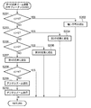
次に、第1の位置のズーム調整のサブルーチン(S200)について説明する。図7に示すように、ステップS201において、変位軌跡の大きさxが第1の長さh1を超えるか否かを判別する。第1の長さh1を超えるときには、ステップS202に進む。第1の長さh1以下であるときには、ステップS203に進む。 Next, the zoom adjustment subroutine (S200) at the first position will be described. As shown in FIG. 7, in step S201, it is determined whether or not the size x of the displacement trajectory exceeds the first length h1. When it exceeds the first length h1, the process proceeds to step S202. When it is equal to or shorter than the first length h1, the process proceeds to step S203.
ステップS202では、現在の撮影光学系11が調整可能な最小倍率に調整されており縮小できないことを通知するメッセージ、例えば、“縮小不可”をディスプレイのリアルタイム動画上に重畳する。メッセージの表示後、第1の位置のズーム調整のサブルーチン(S200)を終了する。
In step S202, a message notifying that the current photographing
ステップS203では、変位軌跡の大きさxが第2の長さh2(<第1の長さh1)を超えるか否かを判別する。第2の長さh2を超えるときには、ステップS204に進む。第2の長さh2以下であるときには、ステップS205に進む。 In step S203, it is determined whether or not the size x of the displacement trajectory exceeds a second length h2 (<first length h1). When it exceeds the second length h2, the process proceeds to step S204. When it is equal to or shorter than the second length h2, the process proceeds to step S205.
ステップS204では、変倍レンズ群11zを第2の位置に変位させる。変倍レンズ群11zの変位後、第1の位置のズーム調整のサブルーチン(S200)を終了する。
In step S204, the
ステップS205では、変位軌跡の大きさxが第3の長さh3(<第2の長さh2)を超えるか否かを判別する。第3の長さh3を超えるときには、ステップS206に進む。第3の長さh3以下であるときには、ステップS207に進む。 In step S205, it is determined whether or not the size x of the displacement trajectory exceeds a third length h3 (<second length h2). When it exceeds the third length h3, the process proceeds to step S206. When it is equal to or shorter than the third length h3, the process proceeds to step S207.
ステップS206では、変倍レンズ群11zを第3の位置に変位させる。変倍レンズ群11zの変位後、第1の位置のズーム調整のサブルーチン(S200)を終了する。
In step S206, the
ステップS207では、変倍レンズ群11zを第4の位置に変位させる。変倍レンズ群11zの変位後ステップS208に進み、変位軌跡の大きさxが第4の長さh4(<第3の長さh3)を超えるか否かを判別する。
In step S207, the
変位軌跡の大きさxが第4の長さh4を超える場合には、第1の位置のズーム調整のサブルーチン(S200)を終了する。 If the size x of the displacement trajectory exceeds the fourth length h4, the zoom adjustment subroutine (S200) at the first position is terminated.
一方、第4の長さh4以下である場合には、ステップS209に進む。ステップS209では、デジタルズームの実行を通知するメッセージをリアルタイム画像上に重畳して表示する。メッセージの表示後ステップS210において、デジタルズームを実行する。デジタルズームの実行後、第1の位置のズーム調整のサブルーチン(S200)を終了する。 On the other hand, if the length is equal to or shorter than the fourth length h4, the process proceeds to step S209. In step S209, a message notifying execution of digital zoom is displayed superimposed on the real-time image. In step S210 after the message is displayed, digital zoom is executed. After execution of the digital zoom, the zoom adjustment subroutine (S200) at the first position is terminated.
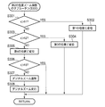
次に、第2の位置のズーム調整のサブルーチン(S300)について説明する。図8に示すように、ステップS301において、変位軌跡の大きさxが第1の長さh1を超えるか否かを判別する。第1の長さh1を超えるときには、ステップS302に進む。第1の長さh1以下であるときには、ステップS303に進む。 Next, the second position zoom adjustment subroutine (S300) will be described. As shown in FIG. 8, in step S301, it is determined whether or not the size x of the displacement trajectory exceeds the first length h1. When it exceeds the first length h1, the process proceeds to step S302. When it is equal to or shorter than the first length h1, the process proceeds to step S303.
ステップS302では、変倍レンズ群11zを第1の位置に変位させる。変倍レンズ群11zの変位後、第2の位置のズーム調整のサブルーチン(S300)を終了する。
In step S302, the
ステップS303では、変位軌跡の大きさxが第2の長さh2を超えるか否かを判別する。第2の長さh2を超えるときには、ステップS304に進む。第2の長さh2以下であるときには、ステップS305に進む。 In step S303, it is determined whether or not the size x of the displacement trajectory exceeds the second length h2. When it exceeds the second length h2, the process proceeds to step S304. When it is equal to or shorter than the second length h2, the process proceeds to step S305.
ステップS304では、変倍レンズ群11zを第3の位置に変位させる。変倍レンズ群11zの変位後、第2の位置のズーム調整のサブルーチン(S300)を終了する。
In step S304, the
ステップS305では、変倍レンズ群11zを第4の位置に変位させる。変倍レンズ群11zの変位後ステップS306に進み、変位軌跡の大きさxが第3の長さh3を超えるか否かを判別する。
In step S305, the
変位軌跡の大きさxが第3の長さh3を超える場合には、第2の位置のズーム調整のサブルーチン(S300)を終了する。 If the size x of the displacement trajectory exceeds the third length h3, the zoom adjustment subroutine (S300) at the second position ends.
一方、第3の長さh3以下である場合には、ステップS307に進む。ステップS307では、デジタルズームの実行を通知するメッセージをリアルタイム画像上に重畳して表示する。メッセージの表示後ステップS308において、デジタルズームを実行する。デジタルズームの実行後、第2の位置のズーム調整のサブルーチン(S300)を終了する。 On the other hand, if the length is equal to or shorter than the third length h3, the process proceeds to step S307. In step S307, a message notifying execution of digital zoom is displayed superimposed on the real-time image. In step S308 after the message is displayed, digital zoom is executed. After executing the digital zoom, the zoom adjustment subroutine (S300) at the second position is terminated.
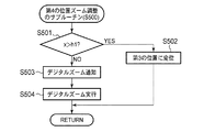
次に、第3の位置のズーム調整のサブルーチン(S400)について説明する。図9に示すように、ステップS401において、変位軌跡の大きさxが第1の長さh1を超えるか否かを判別する。第1の長さh1を超えるときには、ステップS402に進む。第1の長さh1以下であるときには、ステップS403に進む。 Next, the zoom adjustment subroutine (S400) at the third position will be described. As shown in FIG. 9, in step S401, it is determined whether or not the size x of the displacement trajectory exceeds the first length h1. When it exceeds the first length h1, the process proceeds to step S402. When it is equal to or shorter than the first length h1, the process proceeds to step S403.
ステップS402では、変倍レンズ群11zを第2の位置に変位させる。変倍レンズ群11zの変位後、第3の位置のズーム調整のサブルーチン(S400)を終了する。
In step S402, the
ステップS403では、変倍レンズ群11zを第4の位置に変位させる。変倍レンズ群11zの変位後ステップS404に進み、変位軌跡の大きさxが第2の長さh2を超えるか否かを判別する。
In step S403, the
変位軌跡の大きさxが第2の長さh2を超える場合には、第3の位置のズーム調整のサブルーチン(S400)を終了する。 If the size x of the displacement locus exceeds the second length h2, the zoom adjustment subroutine (S400) at the third position is terminated.
一方、第2の長さh2以下である場合には、ステップS405に進む。ステップS405では、デジタルズームの実行を通知するメッセージをリアルタイム画像上に重畳して表示する。メッセージの表示後ステップS406において、デジタルズームを実行する。デジタルズームの実行後、第3の位置のズーム調整のサブルーチン(S400)を終了する。 On the other hand, if the length is equal to or shorter than the second length h2, the process proceeds to step S405. In step S405, a message notifying execution of digital zoom is superimposed on the real-time image and displayed. In step S406 after the message is displayed, digital zoom is executed. After execution of the digital zoom, the zoom adjustment subroutine (S400) at the third position is terminated.
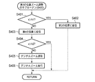
次に、第4の位置のズーム調整のサブルーチン(S500)について説明する。図10に示すように、ステップS501において、変位軌跡の大きさxが第1の長さh1を超えるか否かを判別する。第1の長さh1を超えるときには、ステップS502に進む。第1の長さh1以下であるときには、ステップS503に進む。 Next, the zoom adjustment subroutine (S500) at the fourth position will be described. As shown in FIG. 10, in step S501, it is determined whether or not the size x of the displacement trajectory exceeds the first length h1. If it exceeds the first length h1, the process proceeds to step S502. When it is equal to or shorter than the first length h1, the process proceeds to step S503.
ステップS502では、変倍レンズ群11zを第3の位置に変位させる。変倍レンズ群11zの変位後、第4の位置のズーム調整のサブルーチン(S500)を終了する。
In step S502, the
ステップS503では、デジタルズームの実行を通知するメッセージをリアルタイム画像上に重畳して表示する。メッセージの表示後ステップS504において、デジタルズームを実行する。デジタルズームの実行後、第4の位置のズーム調整のサブルーチン(S500)を終了する。 In step S503, a message notifying execution of digital zoom is displayed superimposed on the real-time image. In step S504 after the message is displayed, digital zoom is executed. After execution of the digital zoom, the zoom adjustment subroutine (S500) at the fourth position ends.
以上のような構成である本実施形態のズーム調整システムによれば、タッチパネルモニタ15のディスプレイ15d入力面上に描かれる軌跡の大きさに応じて定められた位置に変倍レンズ群11zを変位させることが可能である。
According to the zoom adjustment system of the present embodiment having the above-described configuration, the
このような入力方法によれば、変倍レンズ群11zを変位させる光学ズーム調整を迅速且つ正確に実行することが可能である。特に、本実施形態ではリアルタイム画像全体の中の変位軌跡内に表示される一部の光学像がディスプレイ全体に拡大されるように光学ズーム調整が実行されるので、使用者が望む倍率への調整が容易となる。
According to such an input method, it is possible to execute optical zoom adjustment for displacing the
また、本実施形態のズーム調整システムによれば、倍率が最大となるように光学ズームを調整した後には、デジタルズームが実行される。したがって、さらなる望遠撮影が望まれる場合にも、容易に使用者の望む倍率に調整することが可能である。 Further, according to the zoom adjustment system of the present embodiment, digital zoom is executed after adjusting the optical zoom so that the magnification becomes maximum. Therefore, even when further telephoto shooting is desired, it is possible to easily adjust the magnification desired by the user.
なお、本実施形態において、変位軌跡の上下の幅を円の大きさとして検出する構成であるが、他の方法により円の大きさを検出してもよい。例えば、変位軌跡が通過する軌跡に応じて円の大きさを検出する構成でもよい。 In the present embodiment, the upper and lower widths of the displacement locus are detected as the size of the circle, but the size of the circle may be detected by other methods. For example, the configuration may be such that the size of the circle is detected according to the trajectory through which the displacement trajectory passes.
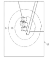
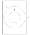
軌跡に応じて円の大きさを検出する構成について簡単に説明する。図11に示すように、ディスプレイ15dの中心を中心とする第1の円形領域CA1と第1の円形領域CA1を内包する第2の円形領域CA2とが定められる。
A configuration for detecting the size of a circle according to the locus will be briefly described. As shown in FIG. 11, a first circular area CA1 centering on the center of the
変位軌跡が第2の円形領域CA2のみを通過するときに、被写体像の倍率を増加させるように変倍レンズ群11zの位置が変位される。さらに、変軌軌跡として描かれた円の大きさは第1の範囲または第1の範囲より大きな範囲である第2の範囲であるかが判別される。判別された円の大きさに基づく倍率で被写体像が拡大される。
When the displacement locus passes only through the second circular area CA2, the position of the variable
変位軌跡が第1の円形領域CA1外であって第2の円形領域CA2のみを通過するときには描かれた円の大きさが第1の範囲に属すると判別して、所定の倍率で被写体像を拡大させるように変倍レンズ群11zの位置が変位される。また、変位軌跡が第1の円形領域CA1のみを通過するときには描かれた円の大きさが第2の範囲に属すると判別して、所定の倍率より大きな倍率で被写体像を拡大させるように変倍レンズ群11zの位置が変位される。このような構成によっても、円の大きさを検出可能である。
When the displacement locus is outside the first circular area CA1 and passes only the second circular area CA2, it is determined that the size of the drawn circle belongs to the first range, and the subject image is captured at a predetermined magnification. The position of the variable
また、本実施形態において、変位軌跡の上下の幅を円の大きさとして検出する構成であるが、任意の方向における幅を円の大きさとして検出してもよい。または、複数の方向における幅を検出し、その中の最大値、最小値、または平均値などを円の大きさとして検出する構成であってもよい。 In the present embodiment, the upper and lower widths of the displacement trajectory are detected as the size of a circle, but the width in an arbitrary direction may be detected as the size of a circle. Or the structure which detects the width | variety in several directions, and detects the maximum value, the minimum value, or an average value in it as a magnitude | size of a circle may be sufficient.
また、本実施形態において、ディスプレイへ15dの接触位置の変位軌跡が円形であるときに変倍レンズ群11zの位置が変位される構成であるが、円形に限定されない。変位軌跡が四角形でも三角形でもよく、閉じられていなくてもよい。さらには、ただの直線であってもよい。変移軌跡の大きさに応じてズーム調整することにより、本実施形態と同様の効果が得られる。
Further, in the present embodiment, the position of the variable
また、本実施形態において、変位軌跡が描く円が小さくなるほど倍率が高くなるように変倍レンズ群11zの位置を調整する構成であるが、大きさに応じて変位させる構成であればよい。
In this embodiment, the position of the variable
また、本実施形態では、変位軌跡の描く円の大きさがディスプレイの幅に近づくように倍率を調整し、描かれる円の内部に表示される画像がディスプレイ15d全面に拡大させる構成であるが、このような倍率調整を行わなくてもよい。このような倍率調整を行わなくても、簡易な入力方法で迅速に正確に倍率調整を行うことは可能である。
In the present embodiment, the magnification is adjusted so that the size of the circle drawn by the displacement trajectory approaches the width of the display, and the image displayed inside the drawn circle is enlarged over the
また、本実施形態では、変倍レンズ群11zは第1〜第4の位置のいずれかに変位可能な構成であるが、複数の位置のいずれかに変位可能な構成であって被写体の倍率を変えられればよい。
In this embodiment, the variable
また、本実施形態では、変位軌跡の描く円の大きさが所定の大きさを超えるときに、倍率を減少させるように変倍レンズ群11zを変位させる構成であるが、倍率の減少は行われなくてもよい。
In the present embodiment, when the size of the circle drawn by the displacement locus exceeds a predetermined size, the
また、本実施形態では、変位軌跡がディスプレイの枠に近い部位を通過する場合に、変倍レンズ群11zの位置を変位させて被写体像の倍率を縮小させる構成であるが、拡大させるための入力方法とは異なる入力方法を検出するときに倍率を縮小する構成であってもよい。例えば、ディスプレイ上の任意の位置への複数回の接触を検出するときに、倍率を縮小してもよい。
In this embodiment, when the displacement locus passes through a part close to the frame of the display, the position of the
また、本実施形態では、変倍レンズ群11zが第4の位置まで変位、すなわち倍率が最大となる位置に変倍レンズ群11zを移動した状態よりもさらに倍率を増加させる場合にはデジタルズームを実行する構成であるが、光学ズーム調整およびデジタルズーム調整のいずれか一方のみが実行される構成であってもよい。他方のズーム調整が従来のズームボタンなどの入力手段への入力であっても、一方のズーム調整を本実施形態に記載の方法に基づいて実行することにより、迅速かつ正確なズーム調整が可能である。
In the present embodiment, the digital zoom is executed when the
また、本実施形態では、光学ズーム調整からデジタルズーム調整に移行するときに、デジタルズーム実行を通知するメッセージが表示される構成であるが、このようなメッセージは表示されなくてもよい。 In this embodiment, a message notifying execution of digital zoom is displayed when shifting from optical zoom adjustment to digital zoom adjustment. However, such a message may not be displayed.
また、本実施形態では、タッチパネルモニタ15が用いられる構成であるが、接触位置を検出可能な入力面を有するポインティングデバイスであって画像が表示されないタッチパネルであってもよい。 In the present embodiment, the touch panel monitor 15 is used. However, the touch panel monitor 15 may be a pointing device having an input surface capable of detecting a contact position and not displaying an image.
10 デジタルカメラ
11z 変倍レンズ群
12 撮像素子
14 CPU
15 タッチパネルモニタ
15d ディスプレイ
16 光学系駆動回路
17 光学系駆動機構
C1、C2 第1、第2の大きさの円
CA1、CA2 第1、第2の円形領域
DESCRIPTION OF
DESCRIPTION OF
Claims (13)
前記入力面への接触が維持されたまま前記接触位置が変位する場合に、前記接触位置の変位の軌跡である変位軌跡を検出する軌跡検出部と、
前記軌跡検出部により検出された前記変位軌跡に応じて、撮影光学系の倍率を調整する光学ズーム調整部とを備える
ことを特徴とするズーム調整システム。 A touch panel that has an input surface and detects the presence or absence of contact with an arbitrary position on the input surface and a contact position that is a contacted position;
A locus detector that detects a displacement locus that is a locus of displacement of the contact position when the contact position is displaced while the contact to the input surface is maintained;
A zoom adjustment system comprising: an optical zoom adjustment unit that adjusts a magnification of a photographing optical system in accordance with the displacement locus detected by the locus detection unit.
前記光学ズーム調整部は、前記変位軌跡が前記第2の領域のみを通過する場合に前記撮影光学系の倍率を増加させ、前記変位軌跡の通過する領域が前記第1の領域のみである場合には前記第1の領域外の前記第2の領域を通過する場合に比べて大きくなるように倍率を増加させる
ことを特徴とする請求項7に記載のズーム調整システム。 On the input surface, a first region and a second region including the first region are defined,
The optical zoom adjustment unit increases the magnification of the photographing optical system when the displacement trajectory passes only the second region, and when the region through which the displacement trajectory passes is only the first region. 8. The zoom adjustment system according to claim 7, wherein the magnification is increased so as to be larger than when passing through the second region outside the first region.
前記光学ズーム調整部は、前記変位軌跡が通過する領域に前記第3の領域が含まれる場合に、前記撮影光学系の倍率を減少させる
ことを特徴とする請求項8に記載のズーム調整システム。 A third area including the second area is defined on the input surface,
The zoom adjustment system according to claim 8, wherein the optical zoom adjustment unit reduces the magnification of the photographing optical system when the third region is included in a region through which the displacement locus passes.
入力面を有し、前記入力面上の任意の位置への接触の有無および接触された位置である接触位置を検出するタッチパネルと、
前記入力面への接触が維持されたまま前記接触位置が変位する場合に、前記接触位置の変位の軌跡である変位軌跡を検出する軌跡検出部と、
前記軌跡検出部により検出された前記変位軌跡に応じて、前記撮影光学系の倍率を調整する光学ズーム調整機構とを備える
ことを特徴とするカメラ。 A photographic optical system with adjustable magnification;
A touch panel that has an input surface and detects the presence or absence of contact with an arbitrary position on the input surface and a contact position that is a contacted position;
A locus detector that detects a displacement locus that is a locus of displacement of the contact position when the contact position is displaced while the contact to the input surface is maintained;
An optical zoom adjustment mechanism that adjusts a magnification of the photographing optical system in accordance with the displacement locus detected by the locus detection unit.
Priority Applications (2)
| Application Number | Priority Date | Filing Date | Title |
|---|---|---|---|
| JP2008317518A JP2010141729A (en) | 2008-12-12 | 2008-12-12 | Zoom adjustment system and camera |
| US12/629,961 US8405741B2 (en) | 2008-12-12 | 2009-12-03 | Zoom adjustment system and camera |
Applications Claiming Priority (1)
| Application Number | Priority Date | Filing Date | Title |
|---|---|---|---|
| JP2008317518A JP2010141729A (en) | 2008-12-12 | 2008-12-12 | Zoom adjustment system and camera |
Publications (1)
| Publication Number | Publication Date |
|---|---|
| JP2010141729A true JP2010141729A (en) | 2010-06-24 |
Family
ID=42240073
Family Applications (1)
| Application Number | Title | Priority Date | Filing Date |
|---|---|---|---|
| JP2008317518A Pending JP2010141729A (en) | 2008-12-12 | 2008-12-12 | Zoom adjustment system and camera |
Country Status (2)
| Country | Link |
|---|---|
| US (1) | US8405741B2 (en) |
| JP (1) | JP2010141729A (en) |
Families Citing this family (1)
| Publication number | Priority date | Publication date | Assignee | Title |
|---|---|---|---|---|
| US9877275B2 (en) | 2016-01-05 | 2018-01-23 | Blackberry Limited | Method and apparatus for multi-SIM selection |
Citations (5)
| Publication number | Priority date | Publication date | Assignee | Title |
|---|---|---|---|---|
| JPH08163541A (en) * | 1994-11-30 | 1996-06-21 | Sharp Corp | Captured image processing device |
| JPH104531A (en) * | 1996-06-14 | 1998-01-06 | Nikon Corp | Information processing device |
| JPH11261872A (en) * | 1998-03-10 | 1999-09-24 | Nikon Corp | Electronic still camera |
| JP2002091649A (en) * | 2000-09-14 | 2002-03-29 | Ricoh Co Ltd | Touch panel type coordinate input device |
| JP2007306250A (en) * | 2006-05-10 | 2007-11-22 | Ricoh Co Ltd | Imaging device, shooting warning method, and computer-readable recording medium |
Family Cites Families (6)
| Publication number | Priority date | Publication date | Assignee | Title |
|---|---|---|---|---|
| JP3977684B2 (en) * | 2002-05-21 | 2007-09-19 | 株式会社東芝 | Digital still camera |
| KR20050066305A (en) * | 2003-12-26 | 2005-06-30 | 삼성전자주식회사 | Image photographing apparatus having appearing and disappearing lens unit |
| CN101049001A (en) * | 2004-10-25 | 2007-10-03 | 松下电器产业株式会社 | mobile phone device |
| EP1829361A1 (en) * | 2004-12-23 | 2007-09-05 | Nokia Corporation | Method for extracting of multiple sub-windows of a scanning area by means of a digital video camera |
| US20070098395A1 (en) * | 2005-10-31 | 2007-05-03 | Battles Amy E | Digital camera user interface |
| JP5117272B2 (en) | 2008-04-30 | 2013-01-16 | Hoya株式会社 | How to adjust the zoom lens |
-
2008
- 2008-12-12 JP JP2008317518A patent/JP2010141729A/en active Pending
-
2009
- 2009-12-03 US US12/629,961 patent/US8405741B2/en not_active Expired - Fee Related
Patent Citations (5)
| Publication number | Priority date | Publication date | Assignee | Title |
|---|---|---|---|---|
| JPH08163541A (en) * | 1994-11-30 | 1996-06-21 | Sharp Corp | Captured image processing device |
| JPH104531A (en) * | 1996-06-14 | 1998-01-06 | Nikon Corp | Information processing device |
| JPH11261872A (en) * | 1998-03-10 | 1999-09-24 | Nikon Corp | Electronic still camera |
| JP2002091649A (en) * | 2000-09-14 | 2002-03-29 | Ricoh Co Ltd | Touch panel type coordinate input device |
| JP2007306250A (en) * | 2006-05-10 | 2007-11-22 | Ricoh Co Ltd | Imaging device, shooting warning method, and computer-readable recording medium |
Also Published As
| Publication number | Publication date |
|---|---|
| US20100149405A1 (en) | 2010-06-17 |
| US8405741B2 (en) | 2013-03-26 |
Similar Documents
| Publication | Publication Date | Title |
|---|---|---|
| JP5620142B2 (en) | Imaging apparatus and imaging method | |
| CN107197141B (en) | Imaging device, imaging method thereof, and storage medium storing tracking program capable of being processed by computer | |
| CN101996044B (en) | Method and apparatus for controlling zoom using a touch screen | |
| US9830947B2 (en) | Image-capturing device | |
| JP6102602B2 (en) | Image processing apparatus, image processing method, image processing program, and imaging apparatus | |
| JP5539045B2 (en) | Imaging apparatus, control method therefor, and storage medium | |
| US10560625B2 (en) | Image shooting apparatus for setting image shooting condition easily and method thereof | |
| JP5379118B2 (en) | IMAGING DEVICE, IMAGING DEVICE CONTROL METHOD, AND PROGRAM THEREOF | |
| JP6107354B2 (en) | Image display device, image display device control method, image display program, and computer-readable recording medium recording the same | |
| JP5281838B2 (en) | Imaging device | |
| JP4843002B2 (en) | IMAGING DEVICE, IMAGING DEVICE CONTROL METHOD, AND COMPUTER PROGRAM | |
| JP2011259285A5 (en) | Imaging apparatus, control method therefor, and storage medium | |
| JP2018066845A (en) | Microscope system | |
| JP2016201626A (en) | Shift element control device, shift element control program, and optical apparatus | |
| JP2016111652A (en) | Imaging apparatus, imaging method and program | |
| JP2009060435A (en) | Camera | |
| JP2010141729A (en) | Zoom adjustment system and camera | |
| JP6025954B2 (en) | Imaging apparatus and control method thereof | |
| JP5744527B2 (en) | Imaging apparatus and control method thereof | |
| JP5730097B2 (en) | Imaging device | |
| JP5847659B2 (en) | Imaging apparatus and control method thereof | |
| JP5220552B2 (en) | Camera control system and digital camera | |
| JP2017175304A (en) | Imaging apparatus | |
| JP2013038632A (en) | Photographing apparatus, mobile information processing terminal having photographing apparatus, and program for controlling mobile information processing terminal | |
| JP6724395B2 (en) | Image display control device, image display control method, and image display control program |
Legal Events
| Date | Code | Title | Description |
|---|---|---|---|
| A625 | Written request for application examination (by other person) |
Free format text: JAPANESE INTERMEDIATE CODE: A625 Effective date: 20111129 |
|
| A711 | Notification of change in applicant |
Free format text: JAPANESE INTERMEDIATE CODE: A712 Effective date: 20111221 |
|
| A977 | Report on retrieval |
Free format text: JAPANESE INTERMEDIATE CODE: A971007 Effective date: 20121004 |
|
| A131 | Notification of reasons for refusal |
Free format text: JAPANESE INTERMEDIATE CODE: A131 Effective date: 20121016 |
|
| A521 | Request for written amendment filed |
Free format text: JAPANESE INTERMEDIATE CODE: A523 Effective date: 20121120 |
|
| A02 | Decision of refusal |
Free format text: JAPANESE INTERMEDIATE CODE: A02 Effective date: 20130312 |