JP2010141663A - Imaging device - Google Patents
Imaging device Download PDFInfo
- Publication number
- JP2010141663A JP2010141663A JP2008316743A JP2008316743A JP2010141663A JP 2010141663 A JP2010141663 A JP 2010141663A JP 2008316743 A JP2008316743 A JP 2008316743A JP 2008316743 A JP2008316743 A JP 2008316743A JP 2010141663 A JP2010141663 A JP 2010141663A
- Authority
- JP
- Japan
- Prior art keywords
- frame
- value
- pixel
- target pixel
- weighted
- Prior art date
- Legal status (The legal status is an assumption and is not a legal conclusion. Google has not performed a legal analysis and makes no representation as to the accuracy of the status listed.)
- Pending
Links
Images
Landscapes
- Studio Devices (AREA)
Abstract
Description
本発明は撮像装置に係り、特にCCD(Charge Coupled Device)やCMOS(Complementary Metal-Oxide Semiconductor)センサなどの固体撮像素子(以下、イメージセンサという)を用いた撮像装置に関する。 The present invention relates to an imaging apparatus, and more particularly to an imaging apparatus using a solid-state imaging device (hereinafter referred to as an image sensor) such as a CCD (Charge Coupled Device) or a CMOS (Complementary Metal-Oxide Semiconductor) sensor.
イメージセンサを使用したビデオカメラやデジタルカメラなどの撮像装置においては、撮像して得た映像信号中に熱雑音やリセットノイズなどのランダムノイズ成分があり、画質劣化の要因となっている。これを解決するためこれまでに様々な発明が提案されている(例えば、特許文献1、2参照)。
In an imaging apparatus such as a video camera or a digital camera using an image sensor, there are random noise components such as thermal noise and reset noise in a video signal obtained by imaging, which causes image quality degradation. In order to solve this, various inventions have been proposed so far (see, for example,
特許文献1には、ランダムノイズを効果的に抑制するために、フレームメモリを用いたフレーム間ノイズ補正やフレーム巡回型ノイズ補正を行う発明が開示されている。また、特許文献2には、動き検出回路を使用し、その動き検出結果によりノイズ補正量を制御する発明が開示されている。
しかしながら、特許文献1記載のフレームメモリを用いたフレーム間ノイズ補正のようなランダムノイズ抑制方法では、数フレーム分の情報を加算して画を作ることになるため、動きの大きな部分、特に高周波領域部分にボケが目立つ。また、特許文献2記載の発明では、動き検出回路の構成が複雑である。
However, in the random noise suppression method such as interframe noise correction using the frame memory described in
本発明は上記の点に鑑みなされたもので、フレームメモリを用いたフレーム間ノイズ補正において、簡易な回路で、フレーム間の動きの大きな領域ではボケを抑制し、かつ、動きの小さい領域ではイメージセンサに起因するランダムノイズを抑制することを可能とし、画質を向上させる撮像装置を提供することを目的とする。 The present invention has been made in view of the above points. In the inter-frame noise correction using the frame memory, a simple circuit suppresses blur in a region where the motion between frames is large, and images in a region where the motion is small. An object of the present invention is to provide an imaging device that can suppress random noise caused by a sensor and improve image quality.
上記の目的を達成するため、本発明は、イメージセンサから出力された画像信号をフレーム単位で記憶する記憶手段と、記憶手段に入力される画像信号の現フレームと記憶手段から出力される現フレームより前のフレームとの間において、処理対象である注目画素の周辺に位置する複数の周辺画素の信号値それぞれのフレーム間差分値を算出するとともに、そのそれぞれのフレーム間差分値の合計値である差分合計値を算出するフレーム差分合計値算出手段と、差分合計値の大きさに応じた重み付け係数を算出する重み付け係数算出手段と、現フレームの注目画素の信号値と前のフレームの注目画素の信号値とを加算した加算平均値と、現フレームの注目画素の信号値とに対して、それぞれ重み付け係数に基づいて重み付けし、更にそのそれぞれ重み付けされた加算平均値と現フレームの注目画素の信号値とを加算した加重平均値を算出し、この算出した加重平均値を撮像画像データとして出力するフレーム加算平均処理手段とを有し、重み付け係数算出手段は、差分合計値の値が小さいほど、加算平均値の割合を現フレームの注目画素の信号値に対して大とするような重み付け係数を算出することを特徴とする。 In order to achieve the above object, the present invention provides a storage means for storing an image signal output from an image sensor in units of frames, a current frame of an image signal input to the storage means, and a current frame output from the storage means. The inter-frame difference value of each of the signal values of a plurality of surrounding pixels located around the target pixel to be processed is calculated between the previous frame and the total value of the respective inter-frame difference values. A frame difference total value calculating means for calculating a difference total value, a weighting coefficient calculating means for calculating a weighting coefficient according to the magnitude of the difference total value, a signal value of a target pixel of a current frame, and a target pixel of a previous frame The weighted average value obtained by adding the signal values and the signal value of the pixel of interest in the current frame are weighted based on the weighting coefficients, respectively. Frame weighted average processing means for calculating a weighted average value obtained by adding the weighted average value and the signal value of the target pixel of the current frame, and outputting the calculated weighted average value as captured image data, The weighting coefficient calculating means calculates a weighting coefficient such that the smaller the difference total value is, the larger the ratio of the addition average value is to the signal value of the target pixel in the current frame.
また、本発明は、上記の前のフレームは、フレーム加算平均処理手段から出力される撮像画像データのフレームであることを特徴とする。 Further, the present invention is characterized in that the previous frame is a frame of captured image data output from the frame addition averaging processing means.
また、本発明は、上記のイメージセンサが、ベイヤ配列のカラーフィルタを搭載しており、加重平均値の算出は、同色のカラーフィルタを通過した画素同士によってなされるようにしてもよい。 In the present invention, the image sensor may include a Bayer array color filter, and the weighted average value may be calculated by pixels passing through the same color filter.
本発明によれば、フレームメモリを用いたフレーム間ノイズ補正において、簡易な回路で、フレーム間の動きの大きな領域ではボケを抑制し、かつ、動きの小さい領域ではイメージセンサに起因するランダムノイズを抑制することが可能となり、画質を向上させることが可能となる。 According to the present invention, in inter-frame noise correction using a frame memory, a simple circuit suppresses blur in a region where movement between frames is large, and random noise caused by an image sensor in a region where movement is small. It becomes possible to suppress the image quality.
次に、本発明の実施形態について図面と共に詳細に説明する。 Next, embodiments of the present invention will be described in detail with reference to the drawings.
(第1の実施の形態)
図1は、本発明になる撮像装置の第1の実施の形態のブロック図を示す。同図に示すように、本実施の形態の撮像装置10は、CCDやCMOSセンサなどのイメージセンサ11と、イメージセンサ11から出力されたアナログ画像信号をデジタル画像信号に変換するA/Dコンバータ12と、デジタル画像信号に対して固定パターンノイズ除去処理などを行うデジタル処理プロセッサ(DSP)13と、固定パターンノイズ除去処理後のデジタル画像信号をフレーム単位で蓄積するフレームメモリ14とを有する。
(First embodiment)
FIG. 1 shows a block diagram of a first embodiment of an imaging apparatus according to the present invention. As shown in the figure, an
更に、撮像装置10は、注目画素の周辺画素に関して前後フレームの信号値の比較を行い、周辺画素フレーム差分合計を算出する周辺画素フレーム差分合計算出回路15と、注目画素に関して、前後フレームの信号値の加算平均値と現フレームの信号値とを重み付け加算して加重平均値を算出して出力するフレーム加算平均処理回路17と、周辺画素フレーム差分合計算出回路15の算出結果によってフレーム加算平均処理回路17における前後フレームの信号値の加算平均値と現フレームの信号値との加重平均時の割合(加算平均強度)を決定する加算平均強度算出回路16と、出力フォーマット変換などの後段処理を行う後段処理DSP18とを有する。
Further, the
次に、本実施の形態の撮像装置10におけるランダムノイズ補正処理について説明する。ランダムノイズ補正処理は、フレームメモリ14、周辺画素フレーム差分合計算出回路15、加算平均強度算出回路16及びフレーム加算平均処理回路17により行われる。
Next, the random noise correction process in the
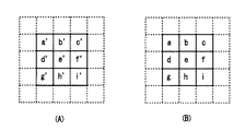
フレームメモリ14は、前段処理DSP13により固定パターンノイズ処理されたデジタル画像信号をフレーム単位で蓄積する。図2(A)、(B)はフレームメモリ14に蓄積される時間的に連続した2フレーム分の注目画素と周辺画素を示す。図2(A)は、フレームメモリ14から出力される前フレームのデジタル画像信号の注目画素e’と、その周辺画素a’〜d’及びf’〜i’を示す。また、図2(B)は、フレームメモリ14に入力される現フレームのデジタル画像信号の注目画素eと、その周辺画素a〜d及びf〜iを示す。なお、図2(A)、(B)中、同じアルファベットの画素は、それぞれイメージセンサ11上の同じ位置の画素を表している。
The
周辺画素フレーム差分合計算出回路15は、前フレームと現フレームに関しての注目画素e’、eの上下左右に隣接する各4つの周辺画素のうち、対応する周辺画素同士の差分合計((b’−b)+(d’−d)+(f’−f)+(h’−h))を算出する。この周辺画素フレーム差分合計は、周辺画素のフレーム間の相関、すなわち画像の動きの大きさを表す。撮像装置10は、この周辺画素フレーム差分合計を算出するにあたり、4つの周辺画素の差分合計を算出することでランダムノイズによる誤差を軽減する。
The peripheral pixel frame difference
この周辺画素フレーム差分合計は、値が小さいほど、注目画素の上下左右に隣接する周辺画素のフレーム間相関が高い、つまり静止画領域であるか、動画領域であっても低周波領域(動きの小さな領域)である可能性が高いことを示す。そのような静止画領域又は低周波領域では、ランダムノイズ成分は目立ち易いが、ランダムノイズ成分を抑えるためにフレーム加算平均を強くかけても元々フレーム間差分が小さいため画のボケは目立ちにくい。また、周辺画素に隣接している注目画素に関しても、同様に周辺画素フレーム差分合計の値が小さいほど、静止画領域か低周波領域である確率が高いと考えられる。 The smaller the value of the peripheral pixel frame difference sum, the higher the inter-frame correlation between neighboring pixels in the vertical and horizontal directions of the target pixel, that is, a still image region or a low frequency region (motion A small area). In such a still image region or low frequency region, the random noise component is easily noticeable, but even if the frame addition average is increased to suppress the random noise component, the difference between the frames is originally small, so the blur of the image is not noticeable. In addition, regarding the target pixel adjacent to the peripheral pixel, similarly, the smaller the total value of the peripheral pixel frame difference, the higher the probability that it is a still image region or a low frequency region.
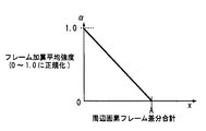
そこで、本実施の形態では、周辺画素フレーム差分合計の値が小さいほど、撮像画像の注目画素が静止画領域か低周波領域であると判断し、フレーム加算平均処理回路17により算出する加重平均値におけるフレーム加算平均値の割合が大きくなるようにフレーム加算平均強度を設定して、ランダムノイズを抑える。そのため、上記の周辺画素フレーム差分合計は、加算平均強度算出回路16において、図3に示すように、周辺画素フレーム差分合計に反比例するような値に正規化される。
Therefore, in the present embodiment, the smaller the value of the peripheral pixel frame difference sum is, the more it is determined that the target pixel of the captured image is the still image region or the low frequency region, and the weighted average value calculated by the frame addition
すなわち、上記のフレーム加算平均強度をαとした場合(0<α<1)、フレーム加算平均強度αは、周辺画素フレーム差分合計をx、定数をA、aとすると、次式で表される。 That is, when the above-mentioned frame addition average intensity is α (0 <α <1), the frame addition average intensity α is expressed by the following equation, where x is the sum of peripheral pixel frame differences, and A is a constant. .
(i) x>Aのとき α=0
(ii) x≦Aのとき α=x/a
ここでの定数Aは、値が大であるほどフレーム加算平均された信号が出力される割合が高くなる。この定数Aはフレームメモリ14に蓄積される画像信号のS/N比などの条件にあわせて設定するものとする。
(i) When x> A, α = 0
(ii) When x ≦ A α = x / a
Here, the larger the value of the constant A, the higher the ratio at which the frame averaged signal is output. This constant A is set according to conditions such as the S / N ratio of the image signal stored in the
フレーム加算平均処理回路17は、図4に示すブロック図の構成により、加算平均強度算出回路16で算出されたフレーム加算平均強度に応じて、注目画素の現在の信号値と前後フレームのフレーム加算平均値とに重み付けを行った後、それらを加算した加重平均値を算出する。フレーム加算平均処理回路17は、算出した加重平均値を撮像画像データとして後段処理DSP18へ出力する。
The frame addition
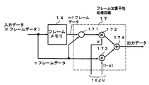
図4に示すように、フレーム加算平均処理回路17は、フレームメモリ14の入力デジタル画像信号である現フレームの注目画素におけるnフレームデータと、フレームメモリ14から出力される前フレームのデジタル画像信号である注目画素におけるn−1フレームデータとのフレーム加算平均値を演算する演算器171と、演算器171から出力される注目画素におけるフレーム加算平均値と第1の重み付け係数とを乗算する第1の乗算器172と、nフレームデータと第2の重み付け係数とを乗算する第2の乗算器173と、乗算器172及び173から出力されたデータを加算して出力する加算器174とから構成されている。
As shown in FIG. 4, the frame addition
ここで、第1の乗算器172が演算器171から出力される注目画素におけるフレーム加算平均値と乗算する第1の重み付け係数は、加算平均強度算出回路16からのフレーム加算平均強度α(0<α<1)である。一方、第2の乗算器173が注目画素における現フレームのnフレームデータと乗算する第2の重み付け係数は、加算平均強度算出回路16からの係数(1−α)である。
Here, the first weighting coefficient by which the first multiplier 172 multiplies the frame addition average value in the pixel of interest output from the
従って、フレーム加算平均処理回路17は、周辺画素フレーム差分合計xが定数A以下の場合は、注目画素及びその周辺画素の領域が静止画領域又は低周波領域であると判断し、乗算器172及び173から出力された注目画素における(n−1)フレームとnフレームの各データのフレーム加算平均値をフレーム加算平均強度αで重み付けした値のデータと、注目画素におけるnフレームデータを(1−α)で重み付けした値のデータとの加算データ(すなわち、加重平均値)を出力する。また、その場合の重み付けは、周辺画素フレーム差分合計xの値が小さいほど、つまり静止画領域又はそれに近いほど、(n−1)フレームとnフレームの各データのフレーム加算平均値の割合を、nフレームデータの割合より多くする。
Therefore, when the peripheral pixel frame difference total x is equal to or smaller than the constant A, the frame addition averaging
一方、フレーム加算平均処理回路17は、周辺画素フレーム差分合計xが定数Aより大の場合は、注目画素及びその周辺画素の領域が、静止画領域及び低周波領域、すなわち動きの小さな領域ではなく、動きの大きな領域であると判断し、このときα=0であるので、乗算器173から出力される注目画素における現フレームのnフレームデータのみを加算器174を通して出力する。これにより、従来生じていたフレーム間ノイズ補正による画像の動きの大きな部分のボケを生じないようにできる。
On the other hand, when the peripheral pixel frame difference total x is larger than the constant A, the frame addition
このように、本実施の形態によれば、フレーム間の注目画素の周辺画素フレーム差分合計xの値によって注目画素及びその周辺画素の領域の画像の動きを画素単位で検出し、この検出した動きが小さいほど、加重平均値における連続する2フレームの注目画素におけるフレーム加算平均値の割合を注目画素の現フレームの割合より大きくすることで、ランダムノイズを抑えることができると共に、動きが大きいときは現フレームの注目画素の信号のみを出力することで従来のフレーム間ノイズ補正による画像の動きの大きな部分のボケを生じないようにできる。 Thus, according to the present embodiment, the movement of the image of the pixel of interest and the area of the peripheral pixel is detected in units of pixels based on the value of the peripheral pixel frame difference sum x of the pixel of interest between frames, and the detected movement The smaller the is, the larger the ratio of the frame addition average value in the pixel of interest of the two consecutive frames in the weighted average value is than the ratio of the current frame of the pixel of interest, so that random noise can be suppressed and the motion is large By outputting only the signal of the pixel of interest in the current frame, it is possible to prevent the blurring of a large portion of the image motion due to the conventional interframe noise correction.
なお、上記の実施の形態において、判定精度を上げたい場合は注目画素の周辺画素として画素a,a’、c,c’、g,g’、i,i’を含めてもよく、またそれ以上広範囲の画素に対しても同様の処理を行い周辺画素フレーム差分合計を算出するようにしてもよい。更に、フレームメモリに余裕があれば、3フレーム以上の信号値よりフレーム差分検出および、フレーム加算平均値算出を行うことで更にノイズ抑制効果を上げることも可能である。 In the above embodiment, when it is desired to increase the determination accuracy, the pixels a, a ′, c, c ′, g, g ′, i, i ′ may be included as peripheral pixels of the target pixel. The same processing may be performed on a wide range of pixels as described above to calculate the peripheral pixel frame difference sum. Furthermore, if there is a margin in the frame memory, it is possible to further improve the noise suppression effect by performing frame difference detection and frame addition average value calculation from signal values of three frames or more.
(第2の実施の形態)
次に、本発明の第2の実施の形態について説明する。図5は、本発明になる撮像装置の第2の実施の形態のブロック図を示す。同図中、図1と同一構成部分には同一符号を付し、その説明を省略する。図5に示す本実施の形態の撮像装置20は、前段処理DSP13とフレームメモリ14の入力との間にスイッチ21を設け、前段処理DSP13の出力にフレームメモリ23を設けるとともに、フレーム加算平均処理回路22の出力データをスイッチ21を介してフレームメモリ14にフィードバックすることにより、注目画素の前フレームまでの加算平均値と現フレームの注目画素におけるフレームデータとの加算平均を使用するフレーム巡回型のノイズ抑制を行う構成である。なお、フレーム加算平均処理回路22は、図4と同様の構成である。
(Second Embodiment)
Next, a second embodiment of the present invention will be described. FIG. 5 shows a block diagram of a second embodiment of the imaging apparatus according to the present invention. In the figure, the same components as those in FIG. The
この実施の形態の撮像装置20では、まず、スイッチ21を端子21a側に接続して前段処理DSP13から出力された現フレームのフレームデータを、スイッチ21を通してフレームメモリ14に供給し、図1に示した第1の実施の形態と同様の動作によりフレーム加算平均処理回路22よりフレーム加算平均処理されたデータ又はnフレームデータを出力する。
In the
続いて、スイッチ21を端子21b側に接続してフレーム加算平均処理回路22より出力されたフレーム加算平均処理されたデータ又はnフレームデータを、(n−1)フレームデータとして、スイッチ21を通してフレームメモリ14に供給し、第1の実施の形態と同様の動作を行わせる。これにより、本実施の形態では、フレーム加算平均処理回路22からは注目画素の前フレーム以前までの加算平均値と注目画素の現フレームの値との加重平均値が出力され、フレーム巡回型のノイズ抑制されたデータが出力される。
Subsequently, the switch 21 is connected to the terminal 21b side, and the frame addition average processed data or n frame data output from the frame addition
(第3の実施の形態)
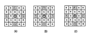
図6は、本発明になる撮像装置の第3の実施の形態で用いられる画像信号の一例を示す。本実施の形態の撮像装置は、ベイヤ配列のカラーフィルタを搭載したイメージセンサを有する。ベイヤ配列のカラーフィルタは、図6(A)〜(C)に示すように、Gで示す緑色光を透過させるG色透過部を市松状に配置し、残りの箇所にBで示す青色光を透過させるB色透過部と、Rで示す赤色光を透過させるR色透過部とを更に市松状に配置した構成である。隣接する透過部は画素ピッチ単位で配置されている。
(Third embodiment)
FIG. 6 shows an example of an image signal used in the third embodiment of the imaging apparatus according to the present invention. The imaging apparatus according to the present embodiment includes an image sensor equipped with a Bayer array color filter. As shown in FIGS. 6A to 6C, the Bayer array color filter has a G-color transmitting portion that transmits green light indicated by G arranged in a checkered pattern, and blue light indicated by B is applied to the remaining portions. In this configuration, a B-color transmitting portion that transmits light and an R-color transmitting portion that transmits red light indicated by R are further arranged in a checkered pattern. Adjacent transmissive portions are arranged in units of pixel pitch.
ここで、図6(A)に二重丸で囲んで示すG色透過部に対応した緑色光入射画素を注目画素とする場合は、同図(A)に一重丸で囲んで示す注目画素よりも2画素ピッチだけ上下左右に配置された4つのG色透過部に対応した緑色光入射画素を周辺画素として、第1又は第2の実施の形態と同様にして周辺画素フレーム差分合計を算出する。 Here, in the case where the green light incident pixel corresponding to the G color transmissive part shown by double circles in FIG. 6A is used as the target pixel, the target pixel shown by a single circle in FIG. Also, the peripheral pixel frame difference sum is calculated in the same manner as in the first or second embodiment, with the green light incident pixels corresponding to the four G color transmission portions arranged vertically and horizontally as much as two pixel pitches as the peripheral pixels. .
また、図6(B)に二重丸で囲んで示すR色透過部に対応した赤色光入射画素を注目画素とする場合は、同図(B)に一重丸で囲んで示す注目画素よりも2画素ピッチだけ上下左右に配置された4つのR色透過部に対応した赤色光入射画素を周辺画素として、第1又は第2の実施の形態と同様にして周辺画素フレーム差分合計を算出する。 In addition, when a red light incident pixel corresponding to the R-color transmission portion indicated by a double circle in FIG. 6B is used as the target pixel, the target pixel indicated by a single circle in FIG. The peripheral pixel frame difference sum is calculated in the same manner as in the first or second embodiment, with the red light incident pixels corresponding to the four R-color transmitting portions arranged vertically and horizontally as much as two pixel pitches as the peripheral pixels.
更に、図6(C)に二重丸で囲んで示すB色透過部に対応した青色光入射画素を注目画素とする場合は、同図(C)に一重丸で囲んで示す注目画素よりも2画素ピッチだけ上下左右に配置された4つのB色透過部に対応した青色光入射画素を周辺画素として、第1又は第2の実施の形態と同様にして周辺画素フレーム差分合計を算出する。 Furthermore, when the blue light incident pixel corresponding to the B-color transmissive portion shown by double circles in FIG. 6C is used as the target pixel, the target pixel shown by single circles in FIG. The peripheral pixel frame difference sum is calculated in the same manner as in the first or second embodiment, with the blue light incident pixels corresponding to the four B-color transmitting portions arranged vertically and horizontally as much as two pixel pitches as the peripheral pixels.
そして、このようにして算出した周辺画素フレーム差分合計の値に基づいて、第1又は第2の実施の形態と同様にして注目画素におけるフレーム加算平均強度を決定し、更にそのフレーム加算平均強度に応じた重み付け処理を行うことで、他の色の画像信号の影響を受けずにランダムノイズ抑制を行うことが可能となる。 Then, based on the value of the peripheral pixel frame difference total calculated in this manner, the frame addition average intensity at the target pixel is determined in the same manner as in the first or second embodiment, and the frame addition average intensity is further determined. By performing the corresponding weighting process, it is possible to suppress random noise without being affected by the image signals of other colors.
なお、本実施の形態において、フレーム差分検出に用いる周辺画素の同色の画素信号の位置は、図6(A)〜(C)に示した2画素ピッチ範囲に限らず、より広範囲のものを使用することも考えられる。また第1の実施の形態と同様に3フレーム以上の信号値よりフレーム差分検出および、フレーム加算平均値算出を行うことで更にノイズ抑制効果を上げることも可能である。 In the present embodiment, the positions of the pixel signals of the same color of the peripheral pixels used for frame difference detection are not limited to the two-pixel pitch range shown in FIGS. It is also possible to do. Similarly to the first embodiment, it is possible to further improve the noise suppression effect by performing frame difference detection and frame addition average value calculation from signal values of three or more frames.
10、20 撮像装置
11 イメージセンサ
12 A/Dコンバータ
13 前段処理DSP(デジタル・シグナル・プロセッサ)
14、23 フレームメモリ
15 周辺画素フレーム差分合計算出回路
16 加算平均強度算出回路
17、22 フレーム加算平均処理回路
18 後段処理DSP(デジタル・シグナル・プロセッサ)
21 スイッチ
171 演算器
172、173 乗算器
174 加算器
10, 20
14, 23
21
Claims (3)
前記記憶手段に入力される画像信号の現フレームと前記記憶手段から出力される前記現フレームより前のフレームとの間において、処理対象である注目画素の周辺に位置する複数の周辺画素の信号値それぞれのフレーム間差分値を算出するとともに、そのそれぞれのフレーム間差分値の合計値である差分合計値を算出するフレーム差分合計値算出手段と、
前記差分合計値の大きさに応じた重み付け係数を算出する重み付け係数算出手段と、
前記現フレームの前記注目画素の信号値と前記前のフレームの前記注目画素の信号値とを加算した加算平均値と、前記現フレームの前記注目画素の信号値とに対して、それぞれ前記重み付け係数に基づいて重み付けし、更にそのそれぞれ重み付けされた加算平均値と前記現フレームの前記注目画素の信号値とを加算した加重平均値を算出し、この算出した加重平均値を撮像画像データとして出力するフレーム加算平均処理手段と
を有し、
前記重み付け係数算出手段は、前記差分合計値の値が小さいほど、前記加算平均値の割合を前記現フレームの前記注目画素の信号値に対して大とするような前記重み付け係数を算出する
ことを特徴とする撮像装置。 Storage means for storing image signals output from the image sensor in units of frames;
Signal values of a plurality of peripheral pixels located around the target pixel to be processed between the current frame of the image signal input to the storage unit and a frame before the current frame output from the storage unit A frame difference total value calculating means for calculating a difference total value that is a total value of the difference values between the frames, and calculating a difference value between the frames;
Weighting coefficient calculating means for calculating a weighting coefficient according to the size of the difference total value;
The weighting coefficient for each of the addition average value obtained by adding the signal value of the target pixel of the current frame and the signal value of the target pixel of the previous frame, and the signal value of the target pixel of the current frame Is calculated, and a weighted average value obtained by adding the weighted average value and the signal value of the target pixel of the current frame is calculated, and the calculated weighted average value is output as captured image data. Frame addition averaging processing means, and
The weighting coefficient calculating means calculates the weighting coefficient such that the smaller the total difference value is, the larger the ratio of the addition average value is to the signal value of the target pixel of the current frame. An imaging device that is characterized.
前記加重平均値の算出は、同色のカラーフィルタを通過した画素同士によってなされる
ことを特徴とする請求項1又は2記載の撮像装置。 The image sensor is equipped with a Bayer array color filter,
The weighted average value is calculated by pixels that have passed through the same color filter.
The imaging apparatus according to claim 1 or 2, wherein
Priority Applications (1)
| Application Number | Priority Date | Filing Date | Title |
|---|---|---|---|
| JP2008316743A JP2010141663A (en) | 2008-12-12 | 2008-12-12 | Imaging device |
Applications Claiming Priority (1)
| Application Number | Priority Date | Filing Date | Title |
|---|---|---|---|
| JP2008316743A JP2010141663A (en) | 2008-12-12 | 2008-12-12 | Imaging device |
Publications (1)
| Publication Number | Publication Date |
|---|---|
| JP2010141663A true JP2010141663A (en) | 2010-06-24 |
Family
ID=42351384
Family Applications (1)
| Application Number | Title | Priority Date | Filing Date |
|---|---|---|---|
| JP2008316743A Pending JP2010141663A (en) | 2008-12-12 | 2008-12-12 | Imaging device |
Country Status (1)
| Country | Link |
|---|---|
| JP (1) | JP2010141663A (en) |
Cited By (12)
| Publication number | Priority date | Publication date | Assignee | Title |
|---|---|---|---|---|
| WO2013073627A1 (en) * | 2011-11-15 | 2013-05-23 | 株式会社 東芝 | Image processing device and method |
| JP2015007816A (en) * | 2013-06-24 | 2015-01-15 | 富士通株式会社 | Image correction apparatus, imaging apparatus, and image correction computer program |
| WO2016152190A1 (en) * | 2015-03-20 | 2016-09-29 | ソニーセミコンダクタソリューションズ株式会社 | Image processing device, image processing system, and image processing method |
| WO2017139198A1 (en) * | 2016-02-08 | 2017-08-17 | Cree, Inc. | Image analysis techniques |
| US9894740B1 (en) | 2017-06-13 | 2018-02-13 | Cree, Inc. | Intelligent lighting module for a lighting fixture |
| US10451229B2 (en) | 2017-01-30 | 2019-10-22 | Ideal Industries Lighting Llc | Skylight fixture |
| US10465869B2 (en) | 2017-01-30 | 2019-11-05 | Ideal Industries Lighting Llc | Skylight fixture |
| CN110858867A (en) * | 2018-08-07 | 2020-03-03 | 瑞昱半导体股份有限公司 | Image processing device and method thereof |
| US10830400B2 (en) | 2018-02-08 | 2020-11-10 | Ideal Industries Lighting Llc | Environmental simulation for indoor spaces |
| US10991215B2 (en) | 2018-03-20 | 2021-04-27 | Ideal Industries Lighting Llc | Intelligent signage |
| US11419201B2 (en) | 2019-10-28 | 2022-08-16 | Ideal Industries Lighting Llc | Systems and methods for providing dynamic lighting |
| JP2025061504A (en) * | 2020-04-24 | 2025-04-10 | 株式会社半導体エネルギー研究所 | Imaging device |
-
2008
- 2008-12-12 JP JP2008316743A patent/JP2010141663A/en active Pending
Cited By (26)
| Publication number | Priority date | Publication date | Assignee | Title |
|---|---|---|---|---|
| WO2013073627A1 (en) * | 2011-11-15 | 2013-05-23 | 株式会社 東芝 | Image processing device and method |
| JP2013126530A (en) * | 2011-11-15 | 2013-06-27 | Toshiba Corp | Image processing device and method |
| CN103210638A (en) * | 2011-11-15 | 2013-07-17 | 株式会社东芝 | Image processing device and method |
| US20140193082A1 (en) * | 2011-11-15 | 2014-07-10 | Toshiba Medical Systems Corporation | Image processing apparatus and method |
| JP2015007816A (en) * | 2013-06-24 | 2015-01-15 | 富士通株式会社 | Image correction apparatus, imaging apparatus, and image correction computer program |
| US9641753B2 (en) | 2013-06-24 | 2017-05-02 | Fujitsu Limited | Image correction apparatus and imaging apparatus |
| US10158790B2 (en) | 2015-03-20 | 2018-12-18 | Sony Semiconductor Solutions Corporation | Image processing apparatus, image processing system, and image processing method |
| WO2016152190A1 (en) * | 2015-03-20 | 2016-09-29 | ソニーセミコンダクタソリューションズ株式会社 | Image processing device, image processing system, and image processing method |
| US10251245B2 (en) | 2016-02-08 | 2019-04-02 | Cree, Inc. | Automatic mapping of devices in a distributed lighting network |
| DE112017000705B4 (en) | 2016-02-08 | 2024-06-20 | Cree Lighting USA LLC (n.d.Ges.d. Staates Delaware) | Image analysis techniques |
| US10192316B2 (en) | 2016-02-08 | 2019-01-29 | Cree, Inc. | Modular lighting fixture |
| WO2017139198A1 (en) * | 2016-02-08 | 2017-08-17 | Cree, Inc. | Image analysis techniques |
| US10306738B2 (en) | 2016-02-08 | 2019-05-28 | Cree, Inc. | Image analysis techniques |
| US11856059B2 (en) | 2016-02-08 | 2023-12-26 | Ideal Industries Lighting Llc | Lighting fixture with enhanced security |
| US11209138B2 (en) | 2017-01-30 | 2021-12-28 | Ideal Industries Lighting Llc | Skylight fixture emulating natural exterior light |
| US10451229B2 (en) | 2017-01-30 | 2019-10-22 | Ideal Industries Lighting Llc | Skylight fixture |
| US10465869B2 (en) | 2017-01-30 | 2019-11-05 | Ideal Industries Lighting Llc | Skylight fixture |
| US10781984B2 (en) | 2017-01-30 | 2020-09-22 | Ideal Industries Lighting Llc | Skylight Fixture |
| US10264657B2 (en) | 2017-06-13 | 2019-04-16 | Cree, Inc. | Intelligent lighting module for a lighting fixture |
| US9894740B1 (en) | 2017-06-13 | 2018-02-13 | Cree, Inc. | Intelligent lighting module for a lighting fixture |
| US10830400B2 (en) | 2018-02-08 | 2020-11-10 | Ideal Industries Lighting Llc | Environmental simulation for indoor spaces |
| US10991215B2 (en) | 2018-03-20 | 2021-04-27 | Ideal Industries Lighting Llc | Intelligent signage |
| CN110858867B (en) * | 2018-08-07 | 2021-12-10 | 瑞昱半导体股份有限公司 | Image processing device and method thereof |
| CN110858867A (en) * | 2018-08-07 | 2020-03-03 | 瑞昱半导体股份有限公司 | Image processing device and method thereof |
| US11419201B2 (en) | 2019-10-28 | 2022-08-16 | Ideal Industries Lighting Llc | Systems and methods for providing dynamic lighting |
| JP2025061504A (en) * | 2020-04-24 | 2025-04-10 | 株式会社半導体エネルギー研究所 | Imaging device |
Similar Documents
| Publication | Publication Date | Title |
|---|---|---|
| JP2010141663A (en) | Imaging device | |
| US8547451B2 (en) | Apparatus and method for obtaining high dynamic range image | |
| US8797462B2 (en) | Image processing apparatus and image processing method | |
| US7916191B2 (en) | Image processing apparatus, method, program, and recording medium | |
| US8508625B2 (en) | Image processing apparatus | |
| CN103202022B (en) | Image processing device and control method thereof | |
| JP4960309B2 (en) | Solid-state imaging device | |
| WO2013145487A1 (en) | Image processing device, image-capturing element, image processing method, and program | |
| JP2008289090A (en) | Imaging signal processing device | |
| JP5541205B2 (en) | Image processing apparatus, imaging apparatus, image processing program, and image processing method | |
| JP2011171885A (en) | Image processing apparatus and image processing method | |
| JP5398667B2 (en) | Image processing device | |
| WO2017154293A1 (en) | Image processing apparatus, imaging apparatus, image processing method, and program | |
| JP5430379B2 (en) | Imaging apparatus, control method thereof, and program | |
| JP2018207413A (en) | Imaging apparatus | |
| JP2010219683A (en) | Image processing device, image processing method, and program | |
| JP5843641B2 (en) | Image processing apparatus and solid-state imaging apparatus | |
| JP2010258620A (en) | Image processing apparatus, image processing method, and program | |
| US10091442B2 (en) | Image processing apparatus and image processing method | |
| US20110122299A1 (en) | Image processing apparatus, image processing method, and camera module | |
| JP2012175169A (en) | Image processor | |
| JP4478981B2 (en) | Color noise reduction method and color imaging apparatus | |
| US9013606B2 (en) | Image processing apparatus and control method thereof | |
| JP4471748B2 (en) | Image signal processing device | |
| JP3697464B2 (en) | Document image processing apparatus, imaging apparatus, and document image processing program |


