JP2010141111A - Solar battery device, method for manufacturing the same, and electronic device - Google Patents
Solar battery device, method for manufacturing the same, and electronic device Download PDFInfo
- Publication number
- JP2010141111A JP2010141111A JP2008315753A JP2008315753A JP2010141111A JP 2010141111 A JP2010141111 A JP 2010141111A JP 2008315753 A JP2008315753 A JP 2008315753A JP 2008315753 A JP2008315753 A JP 2008315753A JP 2010141111 A JP2010141111 A JP 2010141111A
- Authority
- JP
- Japan
- Prior art keywords
- solar cell
- cell device
- resin
- protective material
- solar
- Prior art date
- Legal status (The legal status is an assumption and is not a legal conclusion. Google has not performed a legal analysis and makes no representation as to the accuracy of the status listed.)
- Pending
Links
Images


Classifications
-
- H—ELECTRICITY
- H10—SEMICONDUCTOR DEVICES; ELECTRIC SOLID-STATE DEVICES NOT OTHERWISE PROVIDED FOR
- H10F—INORGANIC SEMICONDUCTOR DEVICES SENSITIVE TO INFRARED RADIATION, LIGHT, ELECTROMAGNETIC RADIATION OF SHORTER WAVELENGTH OR CORPUSCULAR RADIATION
- H10F77/00—Constructional details of devices covered by this subclass
- H10F77/70—Surface textures, e.g. pyramid structures
-
- H—ELECTRICITY
- H02—GENERATION; CONVERSION OR DISTRIBUTION OF ELECTRIC POWER
- H02S—GENERATION OF ELECTRIC POWER BY CONVERSION OF INFRARED RADIATION, VISIBLE LIGHT OR ULTRAVIOLET LIGHT, e.g. USING PHOTOVOLTAIC [PV] MODULES
- H02S10/00—PV power plants; Combinations of PV energy systems with other systems for the generation of electric power
- H02S10/40—Mobile PV generator systems
-
- H—ELECTRICITY
- H10—SEMICONDUCTOR DEVICES; ELECTRIC SOLID-STATE DEVICES NOT OTHERWISE PROVIDED FOR
- H10F—INORGANIC SEMICONDUCTOR DEVICES SENSITIVE TO INFRARED RADIATION, LIGHT, ELECTROMAGNETIC RADIATION OF SHORTER WAVELENGTH OR CORPUSCULAR RADIATION
- H10F19/00—Integrated devices, or assemblies of multiple devices, comprising at least one photovoltaic cell covered by group H10F10/00, e.g. photovoltaic modules
- H10F19/80—Encapsulations or containers for integrated devices, or assemblies of multiple devices, having photovoltaic cells
-
- Y—GENERAL TAGGING OF NEW TECHNOLOGICAL DEVELOPMENTS; GENERAL TAGGING OF CROSS-SECTIONAL TECHNOLOGIES SPANNING OVER SEVERAL SECTIONS OF THE IPC; TECHNICAL SUBJECTS COVERED BY FORMER USPC CROSS-REFERENCE ART COLLECTIONS [XRACs] AND DIGESTS
- Y02—TECHNOLOGIES OR APPLICATIONS FOR MITIGATION OR ADAPTATION AGAINST CLIMATE CHANGE
- Y02E—REDUCTION OF GREENHOUSE GAS [GHG] EMISSIONS, RELATED TO ENERGY GENERATION, TRANSMISSION OR DISTRIBUTION
- Y02E10/00—Energy generation through renewable energy sources
- Y02E10/50—Photovoltaic [PV] energy
Landscapes
- Photovoltaic Devices (AREA)
Abstract
Description
本発明は、太陽電池セルを具備する太陽電池装置に関するものであり、具体的にはその表面に設けられている表面保護材等による発電効率の低下を防止する、並びに搬送性・携帯性に優れた太陽電池装置、その製造方法、並びに電子機器に関する。 The present invention relates to a solar battery device including solar battery cells, and specifically prevents a decrease in power generation efficiency due to a surface protective material or the like provided on the surface, and is excellent in transportability and portability. The present invention relates to a solar cell device, a manufacturing method thereof, and an electronic device.
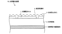
図5は、携帯電子機器に搭載されている太陽電池装置110の概略断面図である。 FIG. 5 is a schematic cross-sectional view of a solar cell device 110 mounted on a portable electronic device.
太陽電池装置110は、携帯電子機器の筺体107上に配置されている支持基板102と、支持基板102上に配置されている複数の太陽電池セル101と、太陽電池セル101および支持基板102上に接着材103を用いて設けられている表面保護材104とを備えている。太陽電池装置110は、太陽光発電により電力を生成して携帯電子機器の電源(2次電池)に蓄電するものである。 The solar cell device 110 includes a support substrate 102 disposed on a housing 107 of a portable electronic device, a plurality of solar cells 101 disposed on the support substrate 102, the solar cells 101, and the support substrate 102. And a surface protective material 104 provided using an adhesive material 103. The solar cell device 110 generates electric power by solar power generation and stores it in a power source (secondary battery) of a portable electronic device.
表面保護材104としては、PET(Poly Ethylene Terephthalate)シートもしくはガラスが用いられている。表面保護材104の光の入射面には、入射光の反射を防止して太陽電池セル101の発電効率を高めるために、図示のようなのこぎり歯状の反射防止加工105(その他、例えば特許文献1・2参照)が施されている。あるいは、表面保護材104の光の入射面には、反射防止加工105と同様な目的のために、反射防止材(不図示)が塗布されている。
従来では、表面保護材104としてPETシートもしくはガラスなどを用いているために太陽電池セル101および支持基板102と表面保護材104とを接着材103を用いて接着しており、この接着材103を入射光が通過する間に熱に変換されて太陽電池セル101の発電効率が低下するという問題を生じる。 Conventionally, since a PET sheet or glass or the like is used as the surface protective material 104, the solar battery cell 101 and the support substrate 102 are bonded to the surface protective material 104 using the adhesive material 103. There is a problem that the power generation efficiency of the solar battery cell 101 is reduced by being converted into heat while the incident light passes.
また、接着材103が必要なために、部品点数が多くなるとともに、太陽電池セル101の面積あたりの質量が大きくなり、携帯電子機器への搭載に適さない、また搬送性に欠けるという問題も生じる。 In addition, since the adhesive 103 is required, the number of parts increases, the mass per area of the solar battery cell 101 increases, and there is a problem that it is not suitable for mounting on a portable electronic device and lacks transportability. .
また、太陽電池装置110の製造時、接着材103が必要なために、また表面保護材104としてPETシートもしくはガラスなどを用いているために反射防止加工105等を施した後に接着を行う必要があるために、工程数が多くなるという問題も生じる。 In addition, since the adhesive material 103 is required at the time of manufacturing the solar cell device 110, and the PET sheet or glass is used as the surface protective material 104, it is necessary to perform the adhesion after applying the antireflection processing 105 or the like. Therefore, there is a problem that the number of processes increases.
本発明は、上記の問題点を鑑みてなされたものであり、その目的は、その表面に設けられている表面保護材等による発電効率の低下を防止する、並びに搬送性・携帯性に優れた太陽電池装置、その製造方法、並びに当該太陽電池装置を備えた電子機器を提供することにある。 The present invention has been made in view of the above-mentioned problems, and its purpose is to prevent a decrease in power generation efficiency due to a surface protective material or the like provided on the surface, as well as excellent transportability and portability. A solar cell device, a manufacturing method thereof, and an electronic device including the solar cell device are provided.
本発明に係る太陽電池装置は、上記課題を解決するために、基板と、上記基板上に配置されている少なくとも1つの太陽電池セルと、上記基板および上記太陽電池セル上に設けられ、太陽電池装置の表面を保護する表面保護材とを備え、上記表面保護材は、合成樹脂から形成されているとともに、光が入射する入射面に、当該光の反射を防止するための反射防止加工が施されていることを特徴としている。 In order to solve the above problems, a solar battery device according to the present invention is provided on a substrate, at least one solar battery cell disposed on the substrate, and on the substrate and the solar battery cell. A surface protective material for protecting the surface of the apparatus, and the surface protective material is formed of a synthetic resin, and an antireflection process for preventing reflection of the light is performed on an incident surface on which the light is incident. It is characterized by being.
また、本発明に係る太陽電池装置の製造方法は、上記課題を解決するために、基板上に少なくとも1つの太陽電池セルを形成する第1工程と、上記基板および上記太陽電池セル上に、合成樹脂を用いて、太陽電池装置の表面を保護する表面保護材を形成する第2工程と、上記表面保護材の光が入射する入射面に、当該光の反射を防止するための反射防止加工を施す第3工程とを有し、上記第3工程は、上記第2工程と同時に行われることを特徴としている。 Moreover, in order to solve the said subject, the manufacturing method of the solar cell apparatus which concerns on this invention is combined with the 1st process of forming at least 1 photovoltaic cell on a board | substrate, and the said board | substrate and the said photovoltaic cell. A second step of forming a surface protection material for protecting the surface of the solar cell device using a resin, and an antireflection process for preventing reflection of the light on the incident surface on which the light of the surface protection material is incident And the third step is performed at the same time as the second step.
上記の構成および方法によれば、合成樹脂を用いて表面保護材を形成するために、従来と異なり接着材が不要となる。よって、従来、この接着材の存在により生じていた、太陽電池セルの発電効率の低下の問題、部品点数が多くなるとともに、太陽電池セルの面積あたりの質量が大きくなり、携帯電子機器への搭載に適さない、また搬送性に欠けるという問題、並びに製造工程数が多くなるという問題を解消できる。つまり、太陽電池セルの発電効率を向上させることができるとともに、携帯性(携帯電子機器への搭載に好適)・搬送性に優れ、並びに製造工程数を少なくすることができる。 According to said structure and method, in order to form a surface protection material using a synthetic resin, an adhesive agent becomes unnecessary unlike the past. Therefore, the problem of reduction in the power generation efficiency of solar cells, which has conventionally occurred due to the presence of this adhesive, the number of parts increases, the mass per area of the solar cells increases, and mounting on portable electronic devices It is possible to solve the problem that the process is not suitable and the transportability is lacking and the problem that the number of manufacturing steps is increased. That is, the power generation efficiency of the solar battery cell can be improved, the portability (suitable for mounting on a portable electronic device) and the transportability are excellent, and the number of manufacturing steps can be reduced.
また、上記表面保護材に反射防止加工を施しているために、光の入射角が入射面に対して90度(入射光が最も高い割合で上記太陽電池セルに到達する角度)を保てない場合であっても、入射光の反射を防止して入射光を上記太陽電池セルに到達せしめ、その発電効率を高めることができる。 In addition, since the surface protective material is subjected to antireflection processing, the incident angle of light cannot maintain 90 degrees with respect to the incident surface (the angle at which incident light reaches the solar cell at the highest rate). Even if it is a case, reflection of incident light can be prevented, incident light can reach the said photovoltaic cell, and the electric power generation efficiency can be improved.
また、上記合成樹脂を用いて上記表面保護材を形成するために、当該形成中に上記反射防止加工を施すことができるため、製造工程数を少なくすることができる。 Moreover, since the said surface protection material is formed using the said synthetic resin, since the said antireflection process can be given during the said formation, the number of manufacturing processes can be decreased.
また、本発明に係る電子機器は、上記課題を解決するために、上記もしくは下記太陽電池装置が、当該太陽電池装置に光が入射可能なように搭載されている、もしくは電気的に接合されていることを特徴としている。 Further, in order to solve the above problems, the electronic device according to the present invention has the above or below solar cell device mounted or electrically joined so that light can enter the solar cell device. It is characterized by being.
以上により、表面に設けられている表面保護材等による発電効率の低下を防止する、並びに搬送性・携帯性に優れた太陽電池装置、その製造方法、並びに当該太陽電池装置を備えた電子機器を提供することができるという効果を奏する。 As described above, a solar cell device which prevents a decrease in power generation efficiency due to a surface protective material or the like provided on the surface, and has excellent transportability and portability, a manufacturing method thereof, and an electronic device including the solar cell device There is an effect that it can be provided.
本発明に係る太陽電池装置は、上記合成樹脂が熱硬化性樹脂であることが好ましい。また、本発明に係る太陽電池装置は、上記合成樹脂が、熱により架橋する架橋材を含む熱可塑性樹脂であることが好ましい。 In the solar cell device according to the present invention, the synthetic resin is preferably a thermosetting resin. In the solar cell device according to the present invention, the synthetic resin is preferably a thermoplastic resin including a cross-linking material that is cross-linked by heat.
上記の構成によれば、上記樹脂が高温において固体となるものであるために、夏期の際など太陽電池装置表面の温度が高くなった場合に上記樹脂(つまり上記表面保護材)の変形が生じ難い。 According to the above configuration, since the resin becomes a solid at a high temperature, the resin (that is, the surface protective material) is deformed when the temperature of the surface of the solar cell device becomes high, such as in summer. hard.
本発明に係る太陽電池装置は、上記樹脂は、全体の重量に対して50%以下の透明な樹脂からなるフィラーを含み、このフィラーは上記樹脂が流動成型される温度において溶解しないガラス転移温度を有するものであることが好ましい。 In the solar cell device according to the present invention, the resin includes a filler made of a transparent resin of 50% or less with respect to the total weight, and the filler has a glass transition temperature at which the resin does not melt at a temperature at which the resin is flow-molded. It is preferable to have it.
上記の構成によれば、上記樹脂にフィラーを加えることで、上記樹脂の成形が容易となる。また、上記フィラーを上記樹脂が流動成型される温度において溶解しないガラス転移温度を有するものとすることで、上記フィラーによる光の反射が生じ難く、太陽電池装置に好適である。また、上記フィラーを加えることで、上記樹脂の熱による変形、および伸び縮みを防止することができる。なお、上記フィラーの含有量は、具体的には、上記全体の重量に対して10%、30%、および50%が一般的である。 According to said structure, the shaping | molding of the said resin becomes easy by adding a filler to the said resin. In addition, since the filler has a glass transition temperature at which the resin is not melted at a temperature at which the resin is fluid-molded, light reflection by the filler hardly occurs, which is suitable for a solar cell device. Further, by adding the filler, it is possible to prevent deformation and expansion / contraction of the resin due to heat. Specifically, the content of the filler is generally 10%, 30%, and 50% with respect to the total weight.
本発明に係る太陽電池装置は、上記樹脂が着色されていることが好ましい。 In the solar cell device according to the present invention, the resin is preferably colored.
上記の構成によれば、外観を美しくして商品価値を高めることができる。なお、上記樹脂に着色せずに、上記樹脂上に着色したカバーを被せてもよい。 According to said structure, an external appearance can be beautiful and a commercial value can be raised. In addition, you may cover the colored cover on the said resin, without coloring the said resin.
本発明に係る太陽電池装置は、上記反射防止加工は上記入射面を梨地に加工したものであることが好ましい。また、本発明に係る太陽電池装置は、上記梨地は、その中心線表面粗さが0.03μm〜2.00μmであることが好ましい。 In the solar cell device according to the present invention, it is preferable that the antireflection processing is obtained by processing the incident surface into a satin finish. Moreover, as for the solar cell apparatus which concerns on this invention, it is preferable that the said satin has the centerline surface roughness of 0.03 micrometer-2.00 micrometers.
上記の構成によれば、梨地加工を採用することでその形状により、また中心線表面粗さを0.03μm〜2.00μmとすることで、高い反射防止効果を期待できる。なお、上記中心線表面粗さは、0.03μm以下であれば平坦な面と同等となり、2.00μm以上であれば梨地の突起部分が大きくなり、反射防止効果を期待できない。 According to said structure, a high antireflection effect can be anticipated by adopting a satin finish depending on its shape and by setting the centerline surface roughness to 0.03 μm to 2.00 μm. If the center line surface roughness is 0.03 μm or less, it is equivalent to a flat surface. If the center line surface roughness is 2.00 μm or more, the matte projections are large, and an antireflection effect cannot be expected.
本発明に係る電子機器は、携帯電話機、デジタルスチルカメラ、デジタルビデオカメラ、携帯ゲーム機、もしくは全地球測位システム装置であることが好ましい。 The electronic device according to the present invention is preferably a mobile phone, a digital still camera, a digital video camera, a portable game machine, or a global positioning system device.
本発明に係る太陽電池装置の製造方法は、上記第3工程が金型を用いて行われることが好ましい。 In the method for manufacturing a solar cell device according to the present invention, the third step is preferably performed using a mold.
切削や研磨などにより上記反射防止加工を行えば、屑が発生して太陽電池装置の発電効率の低下などの問題を招くおそれがある。上記反射防止加工を金型で行えば、屑が発生しないためにそのような問題を生じず、好ましい。 If the antireflection processing is performed by cutting or polishing, scraps are generated, which may cause problems such as a decrease in power generation efficiency of the solar cell device. It is preferable to perform the antireflection processing with a mold, since no waste is generated and no such problem occurs.
本発明に係る太陽電池装置は、基板と、上記基板上に配置されている少なくとも1つの太陽電池セルと、上記基板および上記太陽電池セル上に設けられ、太陽電池装置の表面を保護する表面保護材とを備え、上記表面保護材は、合成樹脂から形成されているとともに、光が入射する入射面に、当該光の反射を防止するための反射防止加工が施されていることを特徴としている。 A solar battery device according to the present invention includes a substrate, at least one solar battery cell disposed on the substrate, and surface protection provided on the substrate and the solar battery cell to protect the surface of the solar battery device. The surface protection material is formed of a synthetic resin, and is characterized in that an antireflection process for preventing reflection of the light is performed on an incident surface on which the light is incident. .
また、本発明に係る太陽電池装置の製造方法は、基板上に少なくとも1つの太陽電池セルを形成する第1工程と、上記基板および上記太陽電池セル上に、合成樹脂を用いて、太陽電池装置の表面を保護する表面保護材を形成する第2工程と、上記表面保護材の光が入射する入射面に、当該光の反射を防止するための反射防止加工を施す第3工程とを有し、上記第3工程は、上記第2工程と同時に行われることを特徴としている。 Moreover, the manufacturing method of the solar cell device according to the present invention includes a first step of forming at least one solar cell on a substrate, and a solar cell device using a synthetic resin on the substrate and the solar cell. A second step of forming a surface protective material for protecting the surface of the surface, and a third step of applying an antireflection process to prevent reflection of the light on the incident surface on which light of the surface protective material is incident. The third step is performed simultaneously with the second step.
上記の構成および方法によれば、合成樹脂を用いて表面保護材を形成するために、従来と異なり接着材が不要となる。よって、従来、この接着材の存在により生じていた、太陽電池セルの発電効率の低下の問題、部品点数が多くなるとともに、太陽電池セルの面積あたりの質量が大きくなり、携帯電子機器への搭載に適さない、また搬送性に欠けるという問題、並びに製造工程数が多くなるという問題を解消できる。つまり、太陽電池セルの発電効率を向上させることができるとともに、携帯性(携帯電子機器への搭載に好適)・搬送性に優れ、並びに製造工程数を少なくすることができる。 According to said structure and method, in order to form a surface protection material using a synthetic resin, an adhesive agent becomes unnecessary unlike the past. Therefore, the problem of reduction in the power generation efficiency of solar cells, which has conventionally occurred due to the presence of this adhesive, the number of parts increases, the mass per area of the solar cells increases, and mounting on portable electronic devices It is possible to solve the problem that the process is not suitable and the transportability is lacking and the problem that the number of manufacturing steps is increased. That is, the power generation efficiency of the solar battery cell can be improved, the portability (suitable for mounting on a portable electronic device) and the transportability are excellent, and the number of manufacturing steps can be reduced.
また、上記表面保護材に反射防止加工を施しているために、光の入射角が入射面に対して90度(入射光が最も高い割合で上記太陽電池セルに到達する角度)を保てない場合であっても、入射光の反射を防止して入射光を上記太陽電池セルに到達せしめ、その発電効率を高めることができる。 In addition, since the surface protective material is subjected to antireflection processing, the incident angle of light cannot maintain 90 degrees with respect to the incident surface (the angle at which incident light reaches the solar cell at the highest rate). Even if it is a case, reflection of incident light can be prevented, incident light can reach the said photovoltaic cell, and the electric power generation efficiency can be improved.
また、上記合成樹脂を用いて上記表面保護材を形成するために、当該形成中に上記反射防止加工を施すことができるため、製造工程数を少なくすることができる。 Moreover, since the said surface protection material is formed using the said synthetic resin, since the said antireflection process can be given during the said formation, the number of manufacturing processes can be decreased.
また、本発明に係る電子機器は、上記課題を解決するために、上記もしくは下記太陽電池装置が、当該太陽電池装置に光が入射可能なように搭載されている、もしくは電気的に接合されていることを特徴としている。 Further, in order to solve the above problems, the electronic device according to the present invention has the above or below solar cell device mounted or electrically joined so that light can enter the solar cell device. It is characterized by being.
以上により、表面に設けられている表面保護材等による発電効率の低下を防止する、並びに搬送性・携帯性に優れた太陽電池装置、その製造方法、並びに当該太陽電池装置を備えた電子機器を提供することができるという効果を奏する。 As described above, a solar cell device which prevents a decrease in power generation efficiency due to a surface protective material or the like provided on the surface, and has excellent transportability and portability, a manufacturing method thereof, and an electronic device including the solar cell device There is an effect that it can be provided.
本発明の実施形態について、図1〜図4を用いて説明すると以下の通りである。 The embodiment of the present invention will be described below with reference to FIGS.
図1は、本実施形態に係る太陽電池装置10の概略断面図である。太陽電池装置10は、太陽電池装置10に光(太陽光)が入射可能なように電子機器(特に携帯電子機器)に搭載されている、もしくは電気的に接合されており、太陽光発電により電力を生成して電子機器の電源(2次電池)に蓄電する。
FIG. 1 is a schematic cross-sectional view of a
太陽電池装置10は、携帯電子機器の筺体7上に配置されている支持基板2と、支持基板2上に配置されている複数の太陽電池セル1と、太陽電池セル1および支持基板2上に設けられている表面保護材4とを備えている。
The
太陽電池セル1は、一般的な太陽電池の構成であって、各セルを直列もしくは並列接続して所望の電圧を得ている。表面保護材4は、太陽電池装置10の表面を保護するものであって、その光の入射面には、入射光の反射を防止して太陽電池セル1の発電効率を高めるために、図示のようなのこぎり歯状の反射防止加工5が施されている。表面保護材4は、合成樹脂から形成されている。
The solar battery cell 1 has a general solar battery configuration, and obtains a desired voltage by connecting the cells in series or in parallel. The surface protective material 4 protects the surface of the
太陽電池装置10は、支持基板2上に太陽電池セル1を形成した後(第1工程)、支持基板2および太陽電池セル1上に、合成樹脂を用いて、表面保護材4を形成する(第2工程)とともに、表面保護材4の上記入射面に反射防止加工5を施して(第3工程)製造される。その後、携帯電子機器の筺体7に支持基板2が取り付けられる。
After forming the solar cells 1 on the support substrate 2 (first step), the
このように本実施形態では、合成樹脂を用いて表面保護材4を形成するために、従来と異なり接着材(図5における接着材103)が不要となる。よって、従来、この接着材の存在により生じていた、太陽電池セルの発電効率の低下の問題、部品点数が多くなるとともに、太陽電池セルの面積あたりの質量が大きくなり、携帯電子機器への搭載に適さない、また搬送性に欠けるという問題、並びに製造工程数が多くなるという問題を解消できる。つまり、太陽電池セル1の発電効率を向上させることができるとともに、太陽電池装置10が携帯性(携帯電子機器への搭載に好適)・搬送性に優れ、並びに製造工程数を少なくすることができる。
Thus, in this embodiment, since the surface protective material 4 is formed using a synthetic resin, an adhesive (adhesive 103 in FIG. 5) becomes unnecessary unlike the conventional case. Therefore, the problem of reduction in the power generation efficiency of solar cells, which has conventionally occurred due to the presence of this adhesive, the number of parts increases, the mass per area of the solar cells increases, and mounting on portable electronic devices It is possible to solve the problem that the process is not suitable and the transportability is lacking and the problem that the number of manufacturing steps is increased. That is, the power generation efficiency of the solar battery cell 1 can be improved, the
また、表面保護材4に反射防止加工5を施しているために、光の入射角が上記入射面に対して90度(入射光が最も高い割合で太陽電池セル1に到達する角度)を保てない場合であっても、入射光の反射を防止して入射光を太陽電池セル1に到達せしめ、その発電効率を高めることができる。なお、特に、携帯電子機器の場合、携帯することにより上記入射面に対して90度を保てない場合が多く、それゆえ上述の効果の観点からも太陽電池装置10は特に携帯電子機器に好適である。
Further, since the surface protection material 4 is provided with the antireflection processing 5, the incident angle of light is maintained at 90 degrees with respect to the incident surface (the angle at which the incident light reaches the solar cell 1 at the highest rate). Even if it is not, it is possible to prevent the reflection of the incident light, to allow the incident light to reach the solar battery cell 1 and to increase the power generation efficiency. In particular, in the case of a portable electronic device, it is often not possible to maintain 90 degrees with respect to the incident surface by carrying it. Therefore, the
また、合成樹脂を用いて表面保護材4を形成するために、当該形成中に反射防止加工5を施すことができるため、製造工程数を少なくすることができる。 Moreover, since the surface protection material 4 is formed using a synthetic resin, the antireflection processing 5 can be performed during the formation, so that the number of manufacturing steps can be reduced.
表面保護材4は、具体的には、熱硬化性樹脂(例えば、エポキシ樹脂)もしくは、熱により架橋する架橋材を含む熱可塑性樹脂(例えば、ポリエチレンもしくはポリエステル)によって形成してもよい。これらの樹脂は高温において固体となるものであるために、上記樹脂を用いれば、夏期の際など太陽電池装置10表面の温度が高くなった場合に上記樹脂(つまり表面保護材4)の変形が生じ難い。
Specifically, the surface protective material 4 may be formed of a thermosetting resin (for example, epoxy resin) or a thermoplastic resin (for example, polyethylene or polyester) including a crosslinking material that is crosslinked by heat. Since these resins become solid at a high temperature, if the resin is used, the resin (that is, the surface protective material 4) is deformed when the surface temperature of the
また、表面保護材4を形成する樹脂は、全体の重量に対して50%以下の透明な樹脂からなるフィラーを含んでいてもよく、そしてこのフィラーは上記樹脂が流動成型される温度において溶解しないガラス転移温度を有するものであることが好ましい。この構成によれば、上記樹脂にフィラーを加えることで、上記樹脂の成形が容易となる。また、フィラーを上記樹脂が流動成型される温度において溶解しないガラス転移温度を有するものとすることで(例えば、各種ガラス,ポリカーボネート,エポキシ樹脂など)、フィラーによる光の反射が生じ難く、太陽電池装置に好適である。また、フィラーを加えることで、上記樹脂の熱による変形、および伸び縮みを防止することができる。なお、フィラーの含有量は、具体的には、上記全体の重量に対して10%、30%、および50%が一般的である。 Further, the resin forming the surface protective material 4 may contain a filler made of a transparent resin of 50% or less with respect to the total weight, and this filler does not dissolve at the temperature at which the resin is fluid molded. It is preferable that it has a glass transition temperature. According to this configuration, the resin can be easily molded by adding a filler to the resin. In addition, since the filler has a glass transition temperature that does not melt at the temperature at which the resin is fluid-molded (for example, various glasses, polycarbonate, epoxy resin, etc.), reflection of light by the filler hardly occurs, and the solar cell device It is suitable for. Further, by adding a filler, it is possible to prevent deformation and expansion / contraction of the resin due to heat. Specifically, the filler content is typically 10%, 30%, and 50% with respect to the total weight.
また、上記樹脂は着色されていてもよい。この着色は、一般的な方法で粉末・液状・ビーズなどの着色材を上記樹脂に混合して行われる。この構成によれば、外観を美しくして商品価値を高めることができる。なお、上記樹脂に着色せずに、上記樹脂上に着色したカバーを被せてもよい。 The resin may be colored. This coloring is performed by mixing a coloring material such as powder, liquid or beads with the resin by a general method. According to this structure, an external appearance can be beautiful and a commercial value can be raised. In addition, you may cover the colored cover on the said resin, without coloring the said resin.
反射防止加工5は、図1に示したようなのこぎり歯状のものでもよいが、図2に示すような梨地に加工されていてもよい。図2は、反射防止加工5の他の例である梨地を示す図である。また、この梨地面(梨地だけでなく、のこぎり歯状の反射防止加工5にも該当)は、中心線表面粗さ(平均の中心線表面粗さ)Raが0.03〜2.00(μm)であることが好ましい。この構成によれば、梨地加工を採用することでその形状により、また中心線表面粗さRaを0.03μm〜2.00μmとすることで、高い反射防止効果を期待できる。なお、中心線表面粗さRaとは、同図に示すように、粗さ曲線を中心線から折り返し、図の斜線を引いた部分の面積を長さLで割った値をμmで表す。また、中心線表面粗さRaは、0.03μm以下であれば平坦な面と同等となり、2.00μm以上であれば梨地の突起部分が大きくなり、反射防止効果を期待できない。 The antireflection processing 5 may be a sawtooth shape as shown in FIG. 1, but may be processed into a satin finish as shown in FIG. 2. FIG. 2 is a diagram showing a satin as another example of the antireflection processing 5. In addition, this pear ground (which is applicable not only to the pear texture but also to the sawtooth-shaped antireflection processing 5) has a center line surface roughness (average center line surface roughness) Ra of 0.03 to 2.00 (μm). ) Is preferable. According to this configuration, a high antireflection effect can be expected by adopting a satin finish depending on the shape and by setting the centerline surface roughness Ra to 0.03 μm to 2.00 μm. As shown in the figure, the center line surface roughness Ra is a value obtained by dividing the roughness curve from the center line and dividing the area of the hatched portion in the figure by the length L in μm. Further, if the center line surface roughness Ra is 0.03 μm or less, it is equivalent to a flat surface, and if the center line surface roughness Ra is 2.00 μm or more, the satin-finished projection becomes large, and an antireflection effect cannot be expected.
図1に示したのこぎり歯状の反射防止加工5は、金型を用いて成型してもよいし、凹凸のついた研磨紙やブラシなどによってこすることによって行ってもよい。一方、図2に示した梨地の反射防止加工5は、金型を用いて成型してもよいし、微細な砂や金属粒子を空気の圧力を用いて表面保護材4に打ち当てることによって行ってもよい。ただし、切削や研磨などにより反射防止加工5を行えば、屑が発生して太陽電池装置10の発電効率の低下などの問題を招くおそれがある。それゆえ、屑が発生しない金型で反射防止加工5を行うことが好ましい。
The sawtooth-shaped antireflection processing 5 shown in FIG. 1 may be molded using a mold, or may be performed by rubbing with a roughened abrasive paper or brush. On the other hand, the satin antireflection processing 5 shown in FIG. 2 may be molded using a mold, or performed by hitting fine sand or metal particles against the surface protective material 4 using air pressure. May be. However, if the antireflection processing 5 is performed by cutting, polishing, or the like, scraps may be generated, leading to problems such as a decrease in power generation efficiency of the
次に、太陽電池装置10の適用例について説明する。上述した太陽電池装置10が搭載される(電気的に接合される)電子機器としては、例えば、携帯電話機、デジタルスチルカメラ、デジタルビデオカメラ、携帯ゲーム機、および全地球測位システム装置(GPS、携帯用および車載用でもよい)などが挙げられる。
Next, an application example of the
図3は、太陽電池装置10を搭載した(電気的に接合されている)携帯電話機20の斜視図である。図4は、太陽電池装置10を搭載した(電気的に接合されている)デジタルスチルカメラ30およびデジタルビデオカメラ35の斜視図である。
FIG. 3 is a perspective view of the mobile phone 20 on which the
携帯電話機20においては、一例として装置の裏側に太陽電池装置10が搭載されている。デジタルスチルカメラ30およびデジタルビデオカメラ35においては、一例として装置の上側や側面側に太陽電池装置10が搭載されている。これら各種装置は、一般的なものであるから、その構造などの詳細については説明を省略する。ここでは、携帯電話機、デジタルスチルカメラ、およびデジタルビデオカメラについてのみ図示したが、その他の携帯ゲーム機および全地球測位システム装置についても、同様に装置の表側、裏側、上部、および側面に太陽電池装置10が配置される。
In the cellular phone 20, as an example, the
本発明は上述した各実施形態に限定されるものではなく、請求項に示した範囲で種々の変更が可能であり、異なる実施形態にそれぞれ開示された技術的手段を適宜組み合わせて得られる実施形態についても本発明の技術的範囲に含まれる。 The present invention is not limited to the above-described embodiments, and various modifications are possible within the scope shown in the claims, and embodiments obtained by appropriately combining technical means disclosed in different embodiments. Is also included in the technical scope of the present invention.
本発明に係る太陽電池装置は、表面に設けられている表面保護材等による発電効率の低下を防止する、並びに搬送性・携帯性に優れており、例えば、携帯電話機、デジタルスチルカメラ、デジタルビデオカメラ、携帯ゲーム機、および全地球測位システム装置などの電子機器(携帯電子機器)に好適に適用できる。また、本発明に係る太陽電池装置の製造方法は、表面に設けられている表面保護材等による発電効率の低下を防止する、並びに搬送性・携帯性に優れた太陽電池装置の製造に好適に利用できる。 The solar cell device according to the present invention prevents a decrease in power generation efficiency due to a surface protective material or the like provided on the surface, and is excellent in transportability and portability. For example, a mobile phone, a digital still camera, a digital video The present invention can be suitably applied to electronic devices (portable electronic devices) such as cameras, portable game machines, and global positioning system devices. Moreover, the method for manufacturing a solar cell device according to the present invention is suitable for manufacturing a solar cell device that prevents a decrease in power generation efficiency due to a surface protective material or the like provided on the surface, and that is excellent in transportability and portability. Available.
1 太陽電池セル
2 支持基板(基板)
4 表面保護材
5 反射防止加工
10 太陽電池装置
Ra 中心線表面粗さ
1 solar cell 2 support substrate (substrate)
4 Surface Protective Material 5
Claims (11)
上記基板上に配置されている少なくとも1つの太陽電池セルと、
上記基板および上記太陽電池セル上に設けられ、太陽電池装置の表面を保護する表面保護材とを備え、
上記表面保護材は、合成樹脂から形成されているとともに、光が入射する入射面に、当該光の反射を防止するための反射防止加工が施されていることを特徴とする太陽電池装置。 A substrate,
At least one solar cell disposed on the substrate;
A surface protective material provided on the substrate and the solar battery cell to protect the surface of the solar battery device;
The solar cell device, wherein the surface protective material is formed of a synthetic resin, and an antireflection process for preventing reflection of the light is performed on an incident surface on which the light is incident.
上記基板および上記太陽電池セル上に、合成樹脂を用いて、太陽電池装置の表面を保護する表面保護材を形成する第2工程と、
上記表面保護材の光が入射する入射面に、当該光の反射を防止するための反射防止加工を施す第3工程とを有し、
上記第3工程は、上記第2工程と同時に行われることを特徴とする太陽電池装置の製造方法。 A first step of forming at least one solar cell on the substrate;
A second step of forming a surface protective material for protecting the surface of the solar battery device on the substrate and the solar battery cell using a synthetic resin;
A third step of applying an antireflection process to prevent the reflection of the light on the incident surface on which the light of the surface protective material is incident;
The method for manufacturing a solar cell device, wherein the third step is performed simultaneously with the second step.
Priority Applications (3)
| Application Number | Priority Date | Filing Date | Title |
|---|---|---|---|
| JP2008315753A JP2010141111A (en) | 2008-12-11 | 2008-12-11 | Solar battery device, method for manufacturing the same, and electronic device |
| US12/633,098 US20100147376A1 (en) | 2008-12-11 | 2009-12-08 | Solar battery device, method of producing same, and electronic device |
| CN2009102541858A CN101752436B (en) | 2008-12-11 | 2009-12-10 | Solar battery device, method of producing same, and electronic device |
Applications Claiming Priority (1)
| Application Number | Priority Date | Filing Date | Title |
|---|---|---|---|
| JP2008315753A JP2010141111A (en) | 2008-12-11 | 2008-12-11 | Solar battery device, method for manufacturing the same, and electronic device |
Publications (1)
| Publication Number | Publication Date |
|---|---|
| JP2010141111A true JP2010141111A (en) | 2010-06-24 |
Family
ID=42239100
Family Applications (1)
| Application Number | Title | Priority Date | Filing Date |
|---|---|---|---|
| JP2008315753A Pending JP2010141111A (en) | 2008-12-11 | 2008-12-11 | Solar battery device, method for manufacturing the same, and electronic device |
Country Status (3)
| Country | Link |
|---|---|
| US (1) | US20100147376A1 (en) |
| JP (1) | JP2010141111A (en) |
| CN (1) | CN101752436B (en) |
Cited By (1)
| Publication number | Priority date | Publication date | Assignee | Title |
|---|---|---|---|---|
| KR101246763B1 (en) | 2011-06-03 | 2013-03-26 | 규 현 최 | Photovolatic cell and fabrication method thereof |
Families Citing this family (4)
| Publication number | Priority date | Publication date | Assignee | Title |
|---|---|---|---|---|
| CN102738251A (en) * | 2012-06-15 | 2012-10-17 | 中国科学院半导体研究所 | Antireflective film for solar battery |
| WO2015115492A1 (en) * | 2014-01-30 | 2015-08-06 | 旭硝子株式会社 | Glass plate with anti-glare function for solar cells |
| CN104883118A (en) * | 2015-05-06 | 2015-09-02 | 苏州建鑫建设集团有限公司 | Solar cell assembly used at building roofs |
| JP7064823B2 (en) * | 2016-08-31 | 2022-05-11 | 株式会社マテリアル・コンセプト | Solar cells and their manufacturing methods |
Citations (5)
| Publication number | Priority date | Publication date | Assignee | Title |
|---|---|---|---|---|
| JPS594179A (en) * | 1982-06-30 | 1984-01-10 | Sharp Corp | amorphous solar cell |
| JPS6088481A (en) * | 1983-10-20 | 1985-05-18 | Kanegafuchi Chem Ind Co Ltd | Solar battery |
| JPS61109157A (en) * | 1984-11-01 | 1986-05-27 | Agency Of Ind Science & Technol | Measurement device for performance of software |
| JPH0951117A (en) * | 1995-05-31 | 1997-02-18 | Sharp Corp | Solar cell module and method of manufacturing the same |
| JPH09191115A (en) * | 1996-01-10 | 1997-07-22 | Canon Inc | Solar cell module |
Family Cites Families (4)
| Publication number | Priority date | Publication date | Assignee | Title |
|---|---|---|---|---|
| US6335479B1 (en) * | 1998-10-13 | 2002-01-01 | Dai Nippon Printing Co., Ltd. | Protective sheet for solar battery module, method of fabricating the same and solar battery module |
| AU764832B2 (en) * | 1999-05-31 | 2003-09-04 | Kaneka Corporation | Solar battery module |
| DE102005043928B4 (en) * | 2004-09-16 | 2011-08-18 | Sharp Kk | Optical semiconductor device and method for its production |
| US20080072950A1 (en) * | 2006-09-08 | 2008-03-27 | Kuo-Len Lin | Communication Apparatus With Solar Cell Charging Capability |
-
2008
- 2008-12-11 JP JP2008315753A patent/JP2010141111A/en active Pending
-
2009
- 2009-12-08 US US12/633,098 patent/US20100147376A1/en not_active Abandoned
- 2009-12-10 CN CN2009102541858A patent/CN101752436B/en not_active Expired - Fee Related
Patent Citations (5)
| Publication number | Priority date | Publication date | Assignee | Title |
|---|---|---|---|---|
| JPS594179A (en) * | 1982-06-30 | 1984-01-10 | Sharp Corp | amorphous solar cell |
| JPS6088481A (en) * | 1983-10-20 | 1985-05-18 | Kanegafuchi Chem Ind Co Ltd | Solar battery |
| JPS61109157A (en) * | 1984-11-01 | 1986-05-27 | Agency Of Ind Science & Technol | Measurement device for performance of software |
| JPH0951117A (en) * | 1995-05-31 | 1997-02-18 | Sharp Corp | Solar cell module and method of manufacturing the same |
| JPH09191115A (en) * | 1996-01-10 | 1997-07-22 | Canon Inc | Solar cell module |
Cited By (1)
| Publication number | Priority date | Publication date | Assignee | Title |
|---|---|---|---|---|
| KR101246763B1 (en) | 2011-06-03 | 2013-03-26 | 규 현 최 | Photovolatic cell and fabrication method thereof |
Also Published As
| Publication number | Publication date |
|---|---|
| CN101752436B (en) | 2011-11-30 |
| CN101752436A (en) | 2010-06-23 |
| US20100147376A1 (en) | 2010-06-17 |
Similar Documents
| Publication | Publication Date | Title |
|---|---|---|
| KR101236016B1 (en) | Backsheet for solar battery and preparation method thereof | |
| JP2010141111A (en) | Solar battery device, method for manufacturing the same, and electronic device | |
| TW201248878A (en) | Machine for manufacturing electrode tape | |
| CN107342342B (en) | High reflection strip for photovoltaic module and photovoltaic module | |
| US20160172518A1 (en) | Reflective microstructured films with microstructures having curved surfaces, for use in solar modules | |
| KR101896058B1 (en) | Manufacturing method for fresnel lens sheet and back cover for mobile phone using the same | |
| CN205333894U (en) | lens protective film | |
| CN107799614A (en) | A kind of solar power generation cell phone rear cover | |
| CN103443932B (en) | Baffle used for solar batteries, its manufacture method, back board member used for solar batteries, backboard used for solar batteries and solar module | |
| JP2016012619A (en) | Heat dissipation structure and solar cell module including heat dissipation structure | |
| CN113167935A (en) | Silicon Fresnel lens on glass substrate for solar concentrator and method of manufacture | |
| US20160172517A1 (en) | Reflecting films with rounded microstructures for use in solar modules | |
| KR101871973B1 (en) | Sheet for solar photovoltaic modules | |
| JP2016072540A (en) | Rear surface protective sheet and solar cell module using the same | |
| CN103279001A (en) | Support structure and camera shooting module with support structure | |
| TW201010097A (en) | Solar cell and manufacturing method therof | |
| CN119730402A (en) | Anti-hidden-crack light photovoltaic module and preparation method thereof | |
| CN208569084U (en) | Resistance to compression reflective membrane resistant to lodging | |
| WO2015078508A1 (en) | Method for producing a photovoltaic device with a textured surface | |
| CN108155259B (en) | Isolation film technology for stacking glass for photovoltaic module | |
| CN118380490A (en) | A directional light-guiding insulating film tape structure and a preparation method thereof and a photovoltaic module | |
| JP2013185336A (en) | Installation structure of film type solar battery | |
| CN205809526U (en) | A kind of curtain with ageing-resistant function | |
| JP2016012618A (en) | Heat dissipation structure and solar cell module including heat dissipation structure | |
| CN203456483U (en) | Underwater solar energy cell structure |
Legal Events
| Date | Code | Title | Description |
|---|---|---|---|
| A977 | Report on retrieval |
Free format text: JAPANESE INTERMEDIATE CODE: A971007 Effective date: 20101026 |
|
| A131 | Notification of reasons for refusal |
Free format text: JAPANESE INTERMEDIATE CODE: A131 Effective date: 20110111 |
|
| A02 | Decision of refusal |
Free format text: JAPANESE INTERMEDIATE CODE: A02 Effective date: 20111213 |