JP2010137568A - Modular printing apparatus - Google Patents
Modular printing apparatus Download PDFInfo
- Publication number
- JP2010137568A JP2010137568A JP2009277516A JP2009277516A JP2010137568A JP 2010137568 A JP2010137568 A JP 2010137568A JP 2009277516 A JP2009277516 A JP 2009277516A JP 2009277516 A JP2009277516 A JP 2009277516A JP 2010137568 A JP2010137568 A JP 2010137568A
- Authority
- JP
- Japan
- Prior art keywords
- module
- interface
- paper
- marking
- feeding
- Prior art date
- Legal status (The legal status is an assumption and is not a legal conclusion. Google has not performed a legal analysis and makes no representation as to the accuracy of the status listed.)
- Pending
Links
Images
Classifications
-
- G—PHYSICS
- G03—PHOTOGRAPHY; CINEMATOGRAPHY; ANALOGOUS TECHNIQUES USING WAVES OTHER THAN OPTICAL WAVES; ELECTROGRAPHY; HOLOGRAPHY
- G03G—ELECTROGRAPHY; ELECTROPHOTOGRAPHY; MAGNETOGRAPHY
- G03G21/00—Arrangements not provided for by groups G03G13/00 - G03G19/00, e.g. cleaning, elimination of residual charge
- G03G21/16—Mechanical means for facilitating the maintenance of the apparatus, e.g. modular arrangements
- G03G21/1642—Mechanical means for facilitating the maintenance of the apparatus, e.g. modular arrangements for connecting the different parts of the apparatus
- G03G21/1652—Electrical connection means
-
- B—PERFORMING OPERATIONS; TRANSPORTING
- B65—CONVEYING; PACKING; STORING; HANDLING THIN OR FILAMENTARY MATERIAL
- B65H—HANDLING THIN OR FILAMENTARY MATERIAL, e.g. SHEETS, WEBS, CABLES
- B65H29/00—Delivering or advancing articles from machines; Advancing articles to or into piles
-
- B—PERFORMING OPERATIONS; TRANSPORTING
- B65—CONVEYING; PACKING; STORING; HANDLING THIN OR FILAMENTARY MATERIAL
- B65H—HANDLING THIN OR FILAMENTARY MATERIAL, e.g. SHEETS, WEBS, CABLES
- B65H2402/00—Constructional details of the handling apparatus
- B65H2402/10—Modular constructions, e.g. using preformed elements or profiles
-
- B—PERFORMING OPERATIONS; TRANSPORTING
- B65—CONVEYING; PACKING; STORING; HANDLING THIN OR FILAMENTARY MATERIAL
- B65H—HANDLING THIN OR FILAMENTARY MATERIAL, e.g. SHEETS, WEBS, CABLES
- B65H2402/00—Constructional details of the handling apparatus
- B65H2402/60—Coupling, adapter or locking means
-
- B—PERFORMING OPERATIONS; TRANSPORTING
- B65—CONVEYING; PACKING; STORING; HANDLING THIN OR FILAMENTARY MATERIAL
- B65H—HANDLING THIN OR FILAMENTARY MATERIAL, e.g. SHEETS, WEBS, CABLES
- B65H2801/00—Application field
- B65H2801/03—Image reproduction devices
- B65H2801/06—Office-type machines, e.g. photocopiers
-
- B—PERFORMING OPERATIONS; TRANSPORTING
- B65—CONVEYING; PACKING; STORING; HANDLING THIN OR FILAMENTARY MATERIAL
- B65H—HANDLING THIN OR FILAMENTARY MATERIAL, e.g. SHEETS, WEBS, CABLES
- B65H2801/00—Application field
- B65H2801/03—Image reproduction devices
- B65H2801/15—Digital printing machines
-
- G—PHYSICS
- G03—PHOTOGRAPHY; CINEMATOGRAPHY; ANALOGOUS TECHNIQUES USING WAVES OTHER THAN OPTICAL WAVES; ELECTROGRAPHY; HOLOGRAPHY
- G03G—ELECTROGRAPHY; ELECTROPHOTOGRAPHY; MAGNETOGRAPHY
- G03G2215/00—Apparatus for electrophotographic processes
- G03G2215/00016—Special arrangement of entire apparatus
- G03G2215/00021—Plural substantially independent image forming units in cooperation, e.g. for duplex, colour or high-speed simplex
-
- G—PHYSICS
- G03—PHOTOGRAPHY; CINEMATOGRAPHY; ANALOGOUS TECHNIQUES USING WAVES OTHER THAN OPTICAL WAVES; ELECTROGRAPHY; HOLOGRAPHY
- G03G—ELECTROGRAPHY; ELECTROPHOTOGRAPHY; MAGNETOGRAPHY
- G03G2221/00—Processes not provided for by group G03G2215/00, e.g. cleaning or residual charge elimination
- G03G2221/16—Mechanical means for facilitating the maintenance of the apparatus, e.g. modular arrangements and complete machine concepts
- G03G2221/1651—Mechanical means for facilitating the maintenance of the apparatus, e.g. modular arrangements and complete machine concepts for connecting the different parts
- G03G2221/166—Electrical connectors
-
- G—PHYSICS
- G03—PHOTOGRAPHY; CINEMATOGRAPHY; ANALOGOUS TECHNIQUES USING WAVES OTHER THAN OPTICAL WAVES; ELECTROGRAPHY; HOLOGRAPHY
- G03G—ELECTROGRAPHY; ELECTROPHOTOGRAPHY; MAGNETOGRAPHY
- G03G2221/00—Processes not provided for by group G03G2215/00, e.g. cleaning or residual charge elimination
- G03G2221/16—Mechanical means for facilitating the maintenance of the apparatus, e.g. modular arrangements and complete machine concepts
- G03G2221/1672—Paper handling
-
- G—PHYSICS
- G03—PHOTOGRAPHY; CINEMATOGRAPHY; ANALOGOUS TECHNIQUES USING WAVES OTHER THAN OPTICAL WAVES; ELECTROGRAPHY; HOLOGRAPHY
- G03G—ELECTROGRAPHY; ELECTROPHOTOGRAPHY; MAGNETOGRAPHY
- G03G2221/00—Processes not provided for by group G03G2215/00, e.g. cleaning or residual charge elimination
- G03G2221/16—Mechanical means for facilitating the maintenance of the apparatus, e.g. modular arrangements and complete machine concepts
- G03G2221/1678—Frame structures
Landscapes
- Engineering & Computer Science (AREA)
- Mechanical Engineering (AREA)
- Physics & Mathematics (AREA)
- General Physics & Mathematics (AREA)
- Electrophotography Configuration And Component (AREA)
- Accessory Devices And Overall Control Thereof (AREA)
Abstract
Description
本件は、用紙に対してモノクロ及びカラーの両方の印刷を行うための柔軟性が要求され、与えられた印刷ジョブに対して2以上の印刷エンジンを用いることができると共に片面又は両面印刷を行う柔軟性が求められる、デジタル印刷システムに関する。 This case requires the flexibility to perform both monochrome and color printing on paper, can use two or more print engines for a given print job, and can perform single-sided or double-sided printing. The present invention relates to a digital printing system that requires high performance.
この種のシステムは、複数の印刷エンジンをタンデム(直列)及びパラレル(並列)のどちらでも使用できるようにし、かつ両面印刷かのうとするために、用紙の経路の変更に関して柔軟性が求められる。したがって、要求された印刷機能を達成するために用紙をユニット内で給紙するために、反転装置や搬送装置の様々な組み合わせが求められる。従来、要求される印刷の柔軟性を実現するために、装置又はシステムは、反転装置、搬送装置、マーキング(印刷)エンジン、定着装置、及び後処理装置などといった様々なコンポーネントから構成されており、これにより、要求される印刷機能の組み合わせを提供している。また、それらコンポーネントがフレーム上に組み立てられ筐体に収納されることで装置の完成品となっている。柔軟性や印刷機能の組み合わせに対する要求が増大するに連れ、筐体内のフレーム上に組み付けられるコンポーネントの数も増えてきた。様々なコンポーネントを相互接続する複雑さや、求められる装置構成のための制御のために、装置は比較的高価なものとなってしまい、これにより要求される性能に比してシステムの市場性が限定されている。 This type of system requires flexibility in changing the paper path in order to allow a plurality of print engines to be used in both tandem (serial) and parallel (parallel) and to perform duplex printing. Therefore, various combinations of reversing devices and conveying devices are required to feed the paper in the unit in order to achieve the required printing function. Conventionally, in order to achieve the required printing flexibility, an apparatus or system is composed of various components such as a reversing device, a conveying device, a marking (printing) engine, a fixing device, and a post-processing device. This provides the required combination of printing functions. In addition, these components are assembled on a frame and stored in a housing, thereby completing the device. As the demand for a combination of flexibility and printing functions increases, the number of components that can be assembled on a frame in a housing has also increased. Due to the complexity of interconnecting various components and the control for the required equipment configuration, the equipment becomes relatively expensive, which limits the marketability of the system compared to the required performance. Has been.
したがって、最新のデジタル印刷装置が実行可能な、求められる複雑な印刷機能を提供すると共に、製造コストが比較的安価でありながらも運用において信頼性があり頑丈な装置においてそのような多機能性を提供することが求められてきた。 Therefore, it provides the required complex printing functions that the latest digital printing devices can perform and provides such versatility in a reliable and rugged device that is relatively inexpensive to manufacture. It has been sought to provide.
この明細書では、モノクロ、カラー、両面、ハイブリッド(例えば両面、片面の混合)、及び片面の印刷を行うことができる複写又はデジタル印刷のためのシステムについて説明する。このシステムは、複数のモジュールユニットを含み、それらモジュールユニットには、搬送装置、反転装置、マーキング(印刷)エンジン及び定着装置が含まれる。それらモジュールユニットは、共通のインタフェース又は互換のインタフェースを有しており、それらモジュールは、構造的には、それぞれ個別の支持フレーム及びハウジング又はキャビネットに収容されている。それらモジュールは、共通の電気的インタフェース、及び共通の搬送/給紙インタフェースを備えており、複数のモジュールを容易に接続することで、要求される印刷能力又は印刷機能を提供できるようにしてもよい。 This specification describes a system for copying or digital printing that can perform monochrome, color, duplex, hybrid (eg, duplex, single sided), and single sided printing. The system includes a plurality of module units, which include a transport device, a reversing device, a marking (printing) engine, and a fixing device. The module units have a common interface or a compatible interface, and the modules are structurally housed in separate support frames and housings or cabinets, respectively. These modules are provided with a common electrical interface and a common transport / feed interface, and a plurality of modules can be easily connected to provide a required printing capability or printing function. .
このようにモジュール方式で構築することにより、要求される個々のシステムのために特別にあつらえた支持構造や筐体を用いて個別に機械を組み立てるコストをかけることなく、共通のコンポーネントを様々な配設構成で用いることができる。基本的な要素群を用いて様々な印刷装置の構成を作ることができ、個々の構成のためのコストをスケールメリットや再利用により節約することができる。 This modular construction allows a variety of common components to be deployed without the cost of individually assembling machines using support structures and enclosures specifically tailored to the required individual system. It can be used in a configuration. Various printing apparatus configurations can be made using basic elements, and the cost for each configuration can be saved by economies of scale and reuse.
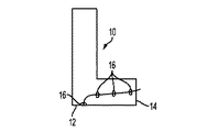
図1aを参照すると、モジュール式の上側の入力/レジストレーション(位置合わせ)ユニット10は、L字形の構成を有しており、隣にある搬送装置又は下側入力/レジストレーションユニット(図5参照)から用紙を受け取ってマーキングエンジンへと排出するために、下側の又は左側のインタフェース(接続部)12と、右側のインタフェース14とを有している。インタフェース12,14は、用紙移動と電気接続のための共通の構成を有している。図1aのユニット10の内部には複数のニップ16が間隔を開けて配設されており、それらニップ16により、ユニット10内の経路に沿って用紙を移動させるとともに、下流側にあるマーキングエンジンへその媒体を搬送するのに先立ってその用紙を見当合わせすなわち位置合わせする。ここで用いる左側インタフェース及び右側インタフェースという用語は、当該モジュールの各端部の近くにある媒体搬送インタフェースを意味するものであり、モジュールの左及び右に向いた垂直な面上に位置するインタフェースに限定されるものではない。
Referring to FIG. 1a, the modular upper input /
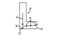
図1bに、L字形のモジュール10の変形バージョンであるモジュール10’を示す。モジュール10’は、隣にある搬送装置又は下側入力/レジストレーションユニット(図5参照)から用紙を受け取ってマーキングエンジンへと排出するために、下側又は左側のインタフェース12’と右側のインタフェース14’とを有している。インタフェース12’,14’は、用紙移動と電気接続のための共通の構成を有している。ユニット10’の内部には複数のニップ16が配設されており、それらニップ16により、ユニット10’内の経路に沿って用紙を移動させる。また、モジュール10’は反転器15を有する。
FIG. 1 b shows a
図2に示すように、モノクロ統合型マーキングエンジン18は、左側インタフェース20と右側インタフェース22とを備えており、左側インタフェース20はL字形の切り欠き部分に設けられている。インタフェース22は、図1a又はず1bのモジュールの右側インタフェース14に、又は共通のインタフェースを備える他のモジュールに、相互接続できるように構成されている。モジュール18のインタフェース20,22は、モジュール18のキャビネット又は筐体の一部となっている。左側インタフェース20と右側インタフェース22は、図1a、図1bのインタフェース12,14との間で電気的な接続を可能とするため及び境界を越えて用紙を移動可能とするための共通の特徴部分を有する。図2のモノクロマーキングエンジン18は、参照符号24で示した搬送ベルトにより、インタフェース22から用紙を排出する。
As shown in FIG. 2, the monochrome integrated marking
図3に示すように、筐体内に専用の支持構造を備えたモジュール式の定着装置26は、内部にニップ28を有する。定着装置26は、図2のマーキングエンジン18の右側インタフェース24からの用紙を、定着装置26自身の左側インタフェース30にて受け取る。定着装置26は、ニップ28から用紙を受け取り、その用紙を搬送ベルト34により右側インタフェース32を通して排出する。右側インタフェース32及び左側インタフェース30は、用紙のための受け取りスロット及び排出スロットと、マーキングエンジン18との接続のための電気接続部を有していてもよい。
As shown in FIG. 3, the
図4に示すように、モジュール式の上側排紙/反転ユニット36は、用紙のための左側インタフェース38と右側インタフェース40とを有し、自身のキャビネットすなわち筐体内に反転器42を備え、媒体(用紙)のカール(反り)の除去及び用紙の流れを作るために一対のニップ44と46を備える。インタフェース38は、用紙の給紙を受けるため、及び図3の定着装置26の右側インタフェース32と電気的に接続するための構成を有する。
As shown in FIG. 4, the modular upper delivery / reversing
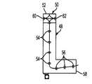
図5aに示すように、自分自身の内部支持構造(図示省略)を備えるモジュール式の下側入力/レジストレーションユニット48が、自身のキャビネット内に収容されている。モジュール48は、大略L字形の構成を有し、左側インタフェース60を有する上端部に連結搬送部50を備える。モジュール48は用紙を下方に搬送するための用紙移動ニップ54を複数備える。第2ニップ56は、用紙を見当合わせすなわち位置合わせし、その用紙を右側インタフェース58へと移動させるように動作する。右側インタフェース58は、図7及び図2のユニットの左側インタフェース77,20と係合する。
As shown in FIG. 5a, a modular lower input /
搬送部50は、上側インタフェース52と右側インタフェース62とを更に備え、これらはインタフェース60,58と共通である。
The
図5bには、L字形の下側入力/レジストレーションモジュール48がモジュール48’として示されている。モジュール48’は左側インタフェース60’を有する上端部に連結搬送部50’を備える。モジュール48’は、用紙を下方に移動させるためのニップ54’を備える。反転器55及び複数の第2ニップ56’が、用紙を見当合わせ及び位置合わせするとともに、用紙を右側インタフェース58’へと移動させる。搬送部50’は、インタフェース60’と共通の上側インタフェース52と右側インタフェース62とを更に備える。
In FIG. 5b, an L-shaped lower input /
図6に示すように、自分自身の筐体すなわちキャビネットの中にあるデュアルモジュール搬送部は、2つの単一のモジュール64を備えており、右側インタフェース70からの用紙を、当該ユニット64とタンデム(直列)接続されて1つの用紙搬送路をなす第2の搬送部64に接続される左側インタフェース68へと搬送する複数のニップ66を有している。搬送部64は、用紙を右から左へ、及び左から右への双方向に移動させることができる双方向のものであってよい。用紙移動及び電気的接続のための右側インタフェース68は図5の入力/レジストレーションモジュール50の右側インタフェース62と係合する。このモジュール式の搬送部は、自分の中を搬送されている用紙の画像又は見当を検出するためのセンサ65を備えていてもよい。
As shown in FIG. 6, the dual module transport unit in its own housing, i.e., the cabinet, includes two
図7に示すように、モジュール式の多色統合型マーキングエンジンは、自分のキャビネットすなわち筐体72内に収容されており、個々の色材の貯蔵ユニット74を備えている。この筐体すなわちキャビネットはL字形の切り欠き部76を有しており、その切り欠き部内に図5のモジュールの右側インタフェース58と接続するための左側インタフェース77を有している。マーキングエンジン72は,用紙を移動させるための搬送ベルト80を有する右側インタフェース78を有する。マーキングエンジン72の右側インタフェース78は、図2のモジュールの右側インタフェース22と類似のものである。図7のモジュール72は4色のハウジングを備えているが、このモジュールは4色以外の色数用のものとして設計されてもよい。もし、この結果構成されるカラーマーキングモジュールが,図7に示した4色システムと異なる幅を持つことになれば、この新たなマーキングモジュールに合わせて、異なる数の搬送モジュール64を設ければよい。
As shown in FIG. 7, the modular multicolor integrated marking engine is housed in its own cabinet or
図8には、上述のデュアル搬送部64の半分が、左側インタフェース68と、ニップ66と、右側インタフェース70とを見せた状態で示されている。
In FIG. 8, half of the above-described
図9には、自身の筐体すなわちキャビネット82内のモジュール式のカラー定着器が示されており、この定着器は用紙受入ニップ86を備える定着要素84を含んでいる。モジュール82は、図7のモジュールの右側インタフェース78との間で、共通の電気的接続及び給紙のための接続部を備える左側インタフェース88を有する。図9の定着器モジュール82は、図3のモジュールの排紙搬送部に類似した排紙搬送部90を備える。
FIG. 9 shows a modular color fuser in its own housing or
図10には、自身の筐体すなわちキャビネット94内の下側排紙/反転モジュールが示されている。モジュール94は、上端部に、用紙を受け取ってニップ98からモジュール82へと排出するための搬送連結部96を備える。搬送連結部96は、左側インタフェース100と右側インタフェース102とを備え、左側インタフェース100は図6及び図8のインタフェース70に類似のものである。出力インタフェース102が、図示省略した用紙スタッカー・フィーダー(蓄積・給紙装置)の左側インタフェース連結部に係合してもよいことが理解されるであろう。搬送連結部96は、上方に向いた用紙インタフェース104を更に備えており、このインタフェース104は図4のモジュールのインタフェース40と類似のものである。上向きインタフェース及び下向きインタフェースは、すべて、左側及び右側のインタフェース連結部に用いられるのと同じ種類のインタフェースを用いて互いに係合(接続)するように設計されていてもよい。図10のモジュールは、マーキングエンジンによって生成されたフェースアップ(すなわち、画像面が上に向いた状態)の出力紙を、両面印刷のため、又は出力すなわち蓄積装置に送るために、フェースダウン(画像面が下に向いた状態)の向きへと反転することができる反転システム97を備える。
FIG. 10 shows a lower paper discharge / reversing module in its own casing, that is, the
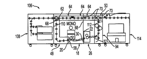
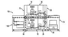
図11に示すように、モノクロ印刷システム106は、キャビネット108に収容されたモジュール式用紙フィーダー(給紙装置)を備え、このフィーダーは図5a、図5bのモジュールの右側インタフェース60と係合する左側インタフェース110を有する。システム106は、図5a又は図5bのモジュール48を備え、このモジュール48は、二連デュアル・タンデム搬送モジュール64の左側インタフェース68に接続される連結搬送右側インタフェース62を有する。モジュール48の右側インタフェース58は、モジュール式モノクロ印刷エンジン18の左側インタフェース20に接続されており、印刷エンジン18は、モジュール式定着装置26の左側インタフェース30に接続される右側インタフェース22を有する。定着装置は、単一の搬送モジュール64を有し、このモジュール64の左側インタフェース68はデュアル搬送モジュールの右側インタフェースに接続されている。定着モジュール26の右側インタフェース32は、排紙/反転モジュール94の左側インタフェースに接続されている。モジュール式後処理装置(フィニッシャー)114の左側インタフェース112は、モジュール94の右側インタフェースに接続されている。図11のシステム106は、モジュール方式で構築されたモノクロ印刷システムであり、そのシステムの主要な構成要素は当該要素自身の筐体又はキャビネットに収容されており、用紙経路と電気的接続のための共通のインタフェース機構により相互に接続されている。
As shown in FIG. 11, the
図12に示すように、他のモジュール構成116は、デュアル・タンデム(すなわちタンデム接続された二連の)搬送モジュール64に接続されたモジュール式の入力/レジストレーションユニット10に接続された給紙モジュール108と、上部に単一の搬送モジュール64を搭載したカラー定着モジュール82に接続された多色マーキングエンジンモジュール72と、を備える。モジュール式定着装置82は、下側反転/排出モジュール94に接続されており、この反転/排出モジュール94の右側インタフェースは、後処理モジュール114の左側インタフェース112に接続されている。図12のシステム116は、多色統合型のマーキングエンジンと定着装置とを提供し、その他のモジュールは図11のシステム106のものと共通のものを利用する。
As shown in FIG. 12, another
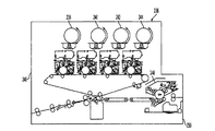
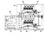
図13に示すように、モジュール式印刷システム118は、フィーダー(給紙)モジュール108と、下側入力/レジストレーションモジュール48と、モノクロ統合型マーキングエンジン18と、を相互接続することにより形成されており、マーキングエンジン18の上にはデュアル(2つの)・タンデム搬送モジュール64と上側入力レジストレーションモジュール10と、第2の、すなわち上側のモノクロ統合型マーキングエンジン18とが載っている。下側のマーキングエンジン18は下側の定着モジュール26に接続されている。上側の統合型マーキングエンジン18は、上側の定着モジュール26に接続されており、下側及び上側の各定着モジュール26はそれぞれ下側の排紙反転モジュール94及び上側の排紙反転モジュール36に接続されている。下側の排紙反転モジュールは後処理モジュール114に接続されている。図13のシステムは、上側及び下側のマーキングエンジン18を通る並行した用紙搬送路を用いて同時に印刷を行いながらも、1つの後処理装置114で最終的な印刷ジョブ結果が組み立てられる。
As shown in FIG. 13, the
図14に示すように、他の印刷システム120は、図1〜10のモジュールを相互接続して構成されており、給紙蓄積(フィーダー・スタッカー)モジュール108と、これに接続された下側入力/レジストレーションモジュール48と、これに接続された下側多色統合型マーキングエンジン72と、この上に載ったデュアル(2つの)・タンデム搬送モジュール64とを備えており、デュアル・タンデム搬送モジュール24の最初の方のモジュールは、縦方向に上側入力/レジストレーションモジュール10を備え、このモジュール10は上側モノクロ統合型マーキングエンジン18に接続されている。下側マーキングエンジン72は、下側定着ユニット82に接続され、ユニット82の上には単一の搬送モジュール64が搭載されている。下側定着モジュール82は下側排紙/反転モジュール92に接続されている。上側定着モジュール26はモジュール82に対して積み重ねられており、モジュール26は上側排紙/反転モジュール36に接続されている。モジュール94の反転連結部96は後処理モジュール114に接続されている。図14のシステム120は、ジョブ結果を組み立てるための共通の後処理装置へと用紙を送る並行した用紙搬送路によりモノクロと多色の印刷を行うことができる。
As shown in FIG. 14, another
図15に示すように、別のモジュール式印刷システム122は、搬送連結モジュール50を備える下側入力/レジストレーションモジュール48に連結された給紙蓄積モジュール108を備える。統合型多色マーキングエンジンモジュール72がモジュール48の下右側のインタフェースに接続されている。マーキングエンジンモジュール72の上にタンデム接続された複数の搬送モジュール64が搭載されており、それらのうちの第1の搬送モジュールは反転モジュール50から用紙を受け取る。上側入力/レジストレーションモジュール10は、搬送連結モジュール50とタンデム接続されたデュアル(二連)の搬送モジュール64のうちの第1のものとの上に搭載されている。モジュール10は、上側多色統合型マーキングエンジン72に対して用紙の入力を行う。下側マーキングエンジンモジュール72は、接続された下側定着モジュール82へと入力し、用紙をそのモジュール82に対して出力・供給する。下側定着モジュール82の上には単一の排出モジュール94が載っている。上側多色マーキングエンジンモジュール72は、上側定着装置26に用紙を給紙し、この定着装置26は用紙を上側排紙/レジストレーションモジュール36へと出力する。排出モジュール94の反転連結部96は用紙を単一の後処理モジュール114に出力する。
As shown in FIG. 15, another
図15のシステムは、上側と下側のマーキングエンジン72によりカラーの印刷を並列した経路で行いつつも、印刷結果の用紙を1つの後処理装置114でまとめることができる。
In the system of FIG. 15, while the color printing is performed by the upper and
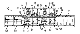
図16に示すように、他の印刷システム124は、搬送連結モジュール50に用紙を流すためのタンデム接続された複数のモジュール式給紙蓄積装置108を有し、モジュール50は下側入力/レジストレーションモジュール48の一部であり、モジュール48は下側多色統合型マーキングエンジン72に用紙を供給すべく接続されたものであり、そのマーキングエンジン72の上にはタンデム接続された複数の搬送モジュール64が搭載されている。上側入力/レジストレーションモジュール10は、用紙を搬送連結モジュール50から受け取って上側モノクロ統合型マーキングエンジン18へと出力し、このマーキングエンジン18は用紙を上側定着モジュール26へと出力する。下側マーキングエンジン72は、下側定着モジュール82に対して用紙を入力するために接続されており、このモジュール82の上には1つの搬送モジュール64が搭載されている。下側定着モジュール82は反転接続部90により下側排紙/反転モジュール94に接続されている。下側排紙モジュール94は第2の下側入力/レジストレーションモジュール48に接続されており、このモジュール48の上には連結搬送モジュールが搭載されている。モジュール48は用紙を第2のカラー統合型マーキングエンジン72に入力し、このマーキングエンジン72の上には1つの搬送モジュール64が載っている。下側マーキングエンジン72は第2の下側定着モジュール82に接続されており、このモジュール82は用紙を第2の下側出力/レジストレーションモジュール94に出力し、このモジュール94の上には搬送連結モジュール50が載っている。第2の上側入力/レジストレーションモジュール10は、用紙を第2の上側モノクロモジュール統合型マーキングエンジン18に用紙を出力し、このマーキングエンジン18は用紙を第2の上側定着モジュール82に出力し、このモジュール82は第2の上側出力/レジストレーションモジュール94に対し用紙を出力するように接続されている。モジュール94の第4の搬送接続部96は、用紙を第1の後処理モジュール114に出力し、このモジュール114は別の後処理モジュール114とタンデム(直列)接続されている。図16のシステムは、モノクロ画像とカラー画像の組み合わせからなるハイブリッド両面印刷や両面印刷を含むモノクロ印刷とカラー印刷の両方について並列印刷機能とタンデム(直列)機能を実現する。
As shown in FIG. 16, another
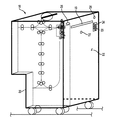
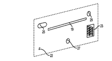
図17では、統合型マーキングエンジンモジュール18が右側インタフェース22を見せており、この右側インタフェース22は、用紙を出力するためのスロット19とプラグイン式の電気接続のためのコネクタピン23を備える電気レセプタクル(受け口)21とを有している。インタフェース22は、隣接するモジュール式ユニットのインタフェースとインタフェース22とを相互接続するためのレジストレーション(位置合わせ)開口部を有している。図17には示していないが、モジュール18の左側インタフェース22も同様の用紙スロット、接続用電気要素、これらは穴及びスロット25,27及び29の中へと突き出るレジストレーションピンを有している。モジュール間の給紙及び電気接続のための相互接続は、コスト低減と組み立て容易性のために共通の形式としている。
In FIG. 17, the integrated
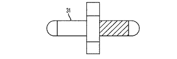
図18aには、インタフェース22の左側部分と電気レセプタクル23と用紙給紙スロット19とが詳細に示されている。図18bには、右側インタフェース22’が、位置合わせピン31と、レセプタクル23に接続される電気コネクタ33とともに示されている。スロット35はスロット19と位置が合うように配設されている。図示のインタフェースは、共通のドッキング用インタフェースの一例に過ぎない。
In FIG. 18a, the left side portion of the
開口部25は、水平方向に延びたスロットとして示されている。下側開口部27はクリアランス穴として示されている。右上側開口部29は、モジュール18が接続される隣のモジュール上に、インタフェース22を位置決めするための接続ピンと緊密に適合する寸法としている。スロット25とクリアランス穴27は、係合用接続ピンに適合するようにしている。図19には、ねじが切られたスタッド(鋲)31が、右側のインタフェースとねじにより係合するようにするために示されている。ねじの切られていないスタッドすなわちピンが、モジュール間を接続するために右側インタフェースのスロット25及びクリアランス穴27に摺動して嵌り合う。
Opening 25 is shown as a horizontally extending slot. The lower opening 27 is shown as a clearance hole. The upper right opening 29 is dimensioned to closely fit the connection pins for positioning the
図20に示すように、フレーム(図示省略)や、筐体すなわちキャビネットなどのような支持構造を持つモジュールは、図1〜10に例示したモジュールとは異なる構成を有している。給紙蓄積装置モジュール126は、キャビネットすなわち筐体内の図示しない内部支持構造に収容されている。モジュール126は、図18a及び図18bに示した給紙、電気的接続及び位置合わせのための開口を有する右側インタフェース128を有する。図20のモジュール群は、「ハイブリッド」印刷能力を持つ単一経路での給紙を採用している。
As illustrated in FIG. 20, a module having a support structure such as a frame (not shown) or a casing, that is, a cabinet has a configuration different from the modules illustrated in FIGS. The sheet
入力/レジストレーションモジュール130は、矩形の統合型マーキングエンジンと相互接続するためのL字形の構成を有する。モジュール130は、左側インタフェース132と、搬送用右側インタフェース134と、第2水平用紙インタフェース136とを有する。
The input /
多色統合型マーキングエンジンモジュール138は、ほぼ矩形の構成を有し、用紙入力部140と、用紙搬送のための多ニップ搬送部142とを有する。
The multicolor integrated
内蔵定着装置を有するモノクロマーキングエンジンモジュール144は、通り抜け用搬送部146と、入力/レジストレーションモジュール130から用紙を受け取るための入力ベルト148とを有する。モジュール144は、出力/レジストレーションモジュールとの接続のための右側インタフェース150を有する、モジュール144は、モノクロ定着装置152をキャビネット内に有する。
The monochrome marking
統合型モノクロ印刷エンジン及び定着装置モジュール154は、図示の筐体すなわちキャビネットの中に内部支持部すなわち内部フレーム(図示省略)を有し、マーキングエンジンから用紙を受け取るための左側インタフェース156を備える。モジュール154は、給紙のための反転装置160を有する搬送部158を備える。モジュール154は、隣接するモジュールとの接続ために図18a及び図18bの右側インタフェース162を有する。
The integrated monochrome printing engine and
多色定着モジュール164は、支持構造(図示省略)を備え、筐体すなわちキャビネット内に収容されている。定着モジュール164は、用紙インタフェース166と、隣接モジュールへの接続のための右側インタフェース168と、図18aと図18bの相互接続のための特徴とを備える。モジュール164は、搬送ベルト170と反転装置172を備える。
The
モノクロマーキングエンジンの他の構成が、符号174で包括的に示されており、この構成は、複数のニップを備える通り抜け用搬送部172と、左側インタフェース174と、右側インタフェース176とを備える。理解されるように、これらインタフェースは、図18a及び図18bの相互接続のための特徴を有する。
Another configuration of the monochrome marking engine is generally indicated by
図21に示すように、単一エンジン印刷システム178は、給紙モジュール126と、その給紙モジュール126に接続された入力/レジストレーションモジュール130と、その入力/レジストレーションモジュール130に接続されたモノクロ統合型マーキングエンジンモジュール174とを備える。マーキングエンジンモジュール174は、モノクロ定着及び反転/排紙モジュール154に接続されている。図21のシステムは、単一用紙搬送路のモノクロ印刷を実現し、モジュール154の右側インタフェース176に対して後処理装置を接続できるようになっている。
As shown in FIG. 21, the single
図22に示すように、他のバージョンのモジュール式印刷システム180は、給紙モジュール126と、これに接続された入力/レジストレーションモジュール130と、このモジュール130に接続された多色統合型マーキングエンジンモジュール138とを有している。マーキングエンジンモジュール138は、多色定着モジュール164に対して出力を行い、このモジュール164の右側インタフェース182は後処理ユニットに接続できるように構成されている。図22のシステム180の各モジュールは、図18a及び図18bに示すように構成されたインタフェース接続部を有していてもよい。図22のシステム18は、両面又は片面の多色印刷のためのモジュール式印刷システムを実現する。
As shown in FIG. 22, another version of the
図23に示すように、他バージョンのモジュール式印刷システム184は、給紙モジュール126と、この給紙モジュール126から用紙を受け取るべく接続された入力/レジストレーションモジュール130とを備える。多色統合型マーキングエンジン138は、入力/レジストレーションモジュール130の上向きインタフェースに接続され、カラー定着装置を備えるモノクロ統合型マーキングエンジン144がそのカラーマーキングエンジン138の右側インタフェースに接続され、モノクロ定着装置154がそのモジュール144の右側インタフェースに接続される。
As shown in FIG. 23, another version of the
このように、図23のシステム184は、カラー印刷又はモノクロ印刷、又はモノクロとカラーの組み合わせについて、片面印刷と両面印刷の両方の能力を備える単一の用紙搬送路を提供する。
Thus, the
図24に示すように、他バージョンの入力モジュール186は、反転器188と左側インタフェース190と右側インタフェース192とを備える。
As shown in FIG. 24, the other version of the
図25に示すように、他バージョンの出力モジュール194は、切り欠き部177内に形成された左側インタフェース196と、当該モジュールの下側の面上のもう一つのインタフェース198とを有する。これらのインタフェースは、図18a及び図18bに示した左側インタフェース及び右側インタフェースと同種のものでよい。
As shown in FIG. 25, another version of the
図26に示すように、他の実施例のモノクロ統合型マーキングエンジン200は、感光体(photoreceptor)アセンブリ202と、定着装置204とを備え、これらは共通のフレームすなわち支持構造(図示省略)に取り付けられ、図26中にて実線で示されている筐体すなわちキャビネットに収容されている。モジュール200は、当該モジュール内を用紙が単一の搬送経路で移動するように、左側インタフェースと右側インタフェースとを有している。
As shown in FIG. 26, a monochrome
図27に示すように、他の実施例のシート状媒体(用紙)給紙装置210は、左側インタフェース212と、用紙の経路を1つ持つ右側インタフェース214とを備えるとともに、支持構造すなわちフレーム(図示省略)を有し、図27中で実線により示されている筐体すなわちキャビネットに収容されている。
As shown in FIG. 27, a sheet-like medium (paper)
図28に示すように、他バージョンの入力モジュール216は、連結搬送部218を備え、左側インタフェース220と上側インタフェース222と右上側インタフェース221と右下側インタフェース224とを有する。モジュール216は、自身の支持構造すなわちフレーム(図示省略)に取り付けられており、図28中で実線により示される筐体すなわちキャビネットに収容されている。
As illustrated in FIG. 28, the
図29に示すように、別バージョンの出力モジュール226は、左上側インタフェース28と、切り欠き部227内に形成された左下側インタフェース230とを備え、上部インタフェース213と右側インタフェース232とはそれらから見て当該モジュールの反対側に形成されている。このモジュールは、搬送連結部234を有し、シート状媒体をバイパス又は搬送のために給紙することができるタイプのものであり、更にマーキング(印刷)済み用紙を、マーキングエンジンから下側インタフェースにて受け取ったり、又はマーキングエンジンから上側インタフェース231を介して受け取ったりする。
As shown in FIG. 29, another version of the
図30に示すように、4色統合型メーキングエンジンモジュール236は、共通の支持フレーム又は支持構造(図示省略)を有し、図30に実線で示すキャビネットを備える。モジュール236は、複数の色材格納装置238,240,242,244と、カラー定着装置246とを備え、それらがキャビネット内に収容されている。モジュール236は、モジュール内をシートが単一経路に沿って移動するよう、沿左側インタフェース248と右側インタフェース250とを有する。
As shown in FIG. 30, the four-color integrated making
図31に示すように、別バージョンのモジュール式印刷システム252は、入力モジュール216に対してシート状媒体を供給する給紙装置210を備え、入力モジュール216は多色マーキングエンジン236の左側インタフェースに接続されている。モジュール216の上側搬送出力部221は、タンデム接続された三連の搬送モジュール64のうちの1番目のモジュールのインタフェースに接続され、この1番目のモジュールは2番目の搬送モジュール64に接続され、この2番目は3番目の搬送モジュール64に接続されるとともに、これら3つはすべてマーキングエンジン236の上部に搭載されている。
As shown in FIG. 31, another version of the
カラーマーキングエンジン236の出力は、出力モジュール226の下側入力部に接続されており、出力モジュール226は、3番目の搬送モジュール64のインタフェースに接続される上側搬送インタフェースを有する。
The output of the
モノクロマーキングモジュール200は、タンデム接続された三連の搬送モジュール64の上に搭載されており、このマーキングモジュール200のインタフェースは、入力モジュール216の上に搭載された入力モジュール186のインタフェースに接続されている。マーキングモジュール200の出力は、単一の搬送モジュール64の入力部に接続されており、このモジュール64は出力モジュール194のインタフェースに接続されており、この出力モジュール194は、出力モジュール226に接続される下側インタフェースを有するとともに、その出力モジュール226の上に搭載されている。このように、図31のシステム252は、単一経路の媒体の流れで同時にカラーとモノクロの印刷出力を実行することができ、シートの片面をカラーで印刷し反対の面をモノクロで印刷する両面印刷を実行することもできる。
The
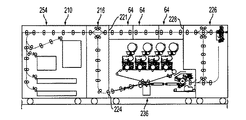
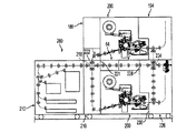
図32に示すように、別バージョンの印刷システム254は入力モジュール210を備え、このモジュールの右側インタフェースは入力モジュール216の左側インタフェースに接続されており、このモジュール216の右上側インタフェースすなわち搬送出力部221は3つの搬送モジュール64のうちの1番目のもののインタフェースに接続され、これら3つの搬送モジュール64は互いにタンデム接続された状態で多色マーキングエンジン236の上に搭載されている。システム254の構成では、入力モジュール216の右下側インタフェース224は、マーキングエンジン236の左側インタフェースに接続されている。3番目の搬送モジュール64の出力は、出力モジュール226の左上側インタフェース228に接続され、出力モジュール226の左下側インタフェースは、マーキングエンジン236の右側インタフェースに接続されている。このように、図32のシステム254は、そのマーキングエンジン236を通るように媒体を搬送する能力と、マーキングエンジン236をバイパスするように媒体を搬送する能力との両方を備える、多色マーキングエンジンを通る単一経路の媒体フローを提供する。
As shown in FIG. 32, another version of the
図33に示すように、他のバージョンのモジュール式印刷システム256は、給紙モジュール210を備え、このモジュール210の右側インタフェースは入力モジュール216の左側インタフェースに接続されており、この入力モジュール216の上側の搬送部分の右側インタフェース221は二連のタンデム接続された搬送モジュール64のうちの1番目のモジュールの左側インタフェースに接続されている。入力モジュール216の右下側インタフェースは、モノクロマーキングエンジン200の左側インタフェースに接続されており、このマーキングエンジン200の上面には二連の搬送モジュール64が搭載されている。二連の搬送モジュール64のうちの2番目のモジュールの出力は、出力モジュール226の左上側インタフェースに接続されており、このモジュール226の左下側インタフェースはマーキングエンジン200の右側インタフェースに接続されている。このように、図33のシステムは、用紙上に片面又は両面のモノクロ印刷を行い、マーキングエンジンを通る単一経路を提供することができ、用紙をマーキングエンジンを直接通過させ、バイパスさせる能力を有する。
As shown in FIG. 33, another version of the
図34に示すように、他のバージョンのモジュール式印刷システム258は、給紙モジュール210を備え、このモジュール210の右側インタフェースは入力モジュール216の左側インタフェースに接続されており、この入力モジュール216の右下側インタフェースは、多色マーキングエンジン236の左側インタフェースに接続されている。このマーキングエンジン200の上にはタンデム接続された三連の搬送モジュール64が縦に積まれている。三連のタンデム接続された搬送モジュール64のうちの1番目のモジュールの左側インタフェースは、入力モジュール216の上側インタフェース221に接続されている。多色マーキングエンジン236の出力部は、出力モジュール226の下側入力部に接続されており、出力モジュール226の左上側インタフェースは3番目の搬送モジュール64の右側インタフェース228に接続されている。
As shown in FIG. 34, another version of the
図34のシステム258において、入力モジュール216の上には入力モジュール186が縦に積まれており、このモジュール186の入力部はモジュール216の連結搬送部218の上側インタフェース222に接続され、モジュール186の出力部は下側のマーキングモジュール236の上に搭載された第2の多色マーキングモジュール236の入力部に接続されている。第2の多色マーキングモジュール236の出力部は、出力モジュール194の左側インタフェース230に接続されている。このように、図34のモジュール式印刷システム258は、2つの多色マーキングモジュールを用いて並列的に印刷し、出口では媒体用紙の流れを単一の経路とすることができる能力を備える。
In the
図35に示すように、他のバージョンのモジュール式印刷システム260は、給紙モジュール210を備え、このモジュール210の出力部は入力モジュール216の左側インタフェースに接続されており、この入力モジュール216の上部の搬送側221の出力部は、モノクロマーキングモジュール200の上に搭載されたタンデム接続された二連の搬送モジュール64のうちの1番目のものの入力に接続されている。2番目の搬送モジュール64の出力部は、出力モジュール226の左上側インタフェース228に接続されており、出力モジュール226の左下側のインタフェース230はマーキングモジュール200の出力部に接続されている。第2の入力モジュール186は、下側の入力モジュール216の上に搭載されており、この上側の入力モジュール186の入力部は、モジュール216の搬送連結部218の上側インタフェース222に接続されており、このモジュール186の右側インタフェースは第2のモノクロマーキングモジュール200の左側インタフェースに接続されており、第2のモノクロマーキングモジュール200は、二連の搬送モジュール64の上に搭載されている。
As shown in FIG. 35, another version of the
上側のマーキングエンジン200の出力部は、下側の出力モジュール226の上に縦に積み上げる構成で搭載された第2の出力モジュール194の入力部に接続されている。上側の出力モジュール194のインタフェースは、下側の出力モジュール226の搬送連結部234の上側インタフェースに接続されている。このように、図35のシステム260は、出口では単一経路の用紙フローとしつつも、2つのモノクロマーキングエンジンを用いて同時に二連印刷を行うことができる。図35のシステムは、どちらのマーキングモジュール200でも、他のマーキングモジュール200でのマーキング(印刷)動作とは独立に、片面又は両面印刷を行うことができる。更に、用紙を印刷することなく、図35のシステム内を搬送することもできる。
The output unit of the
このように、この明細書では、片面印刷と両面印刷のどちらが必要か、用紙の一方の面にカラーでマーキングしもう一方の面にモノクロでマーキングするハイブリッド印刷が必要かどうかなどの、マーキング機能やスピード奈ドンも様々な組み合わせを実現するための、1つ又は複数のマーキングエンジンモジュールを備えた様々なデジタル印刷システムを説明した。この明細書にて説明した各モジュールは、それぞれ支持構造とキャビネット(筐体)とを備えており、そのモジュールのキャビネットの入力部と右側インタフェースとに用紙入出力と電気接続のための共通の構造を有している。このように、この明細書のシステムのモジュール方式の構成は、要求される様々な印刷構成のための複数の機能の組み合わせを可能とすることで、システムのコストを(モジュールの組み合わせではなく、最初から1つの装置として設計される)既成の印刷装置のコストよりも実質的に低減することができる。 Thus, in this specification, the marking function, such as whether single-sided printing or double-sided printing is required, or whether hybrid printing is required, where one side of the paper is marked in color and the other side is marked in monochrome, Speedna Don also described various digital printing systems with one or more marking engine modules to achieve various combinations. Each module described in this specification has a support structure and a cabinet (housing), and a common structure for paper input / output and electrical connection between the input section and the right interface of the module cabinet. have. Thus, the modular configuration of the system in this specification allows for the combination of multiple functions for the various printing configurations required, thereby reducing system cost (first, not module combination). Can be substantially less than the cost of off-the-shelf printing devices (designed as a single device).
10 入力/レジストレーションモジュール、12,14 インタフェース、16 ニップ、18 モノクロ統合型マーキングエンジン、20,22 インタフェース、26 定着装置、30,32 インタフェース。 10 input / registration module, 12, 14 interface, 16 nip, 18 monochrome integrated marking engine, 20, 22 interface, 26 fixing device, 30, 32 interface.
Claims (4)
(a)シート媒体の給紙又は搬送と電気的接続とのための着脱自在の左側インタフェースと右側インタフェースとを備えた個別の支持構造、を有する少なくとも1つのマーキングエンジンモジュールと、
(b)シート媒体の給紙又は搬送と電気的接続とのための着脱自在の左側インタフェースと右側インタフェースとを備えた個別の支持構造を備えた媒体レジストレーションシステム、を有する着脱自在の入力モジュールと、
(c)シート媒体の給紙又は搬送と電気的接続とのための着脱自在の左側インタフェースと右側インタフェースとを備えた個別の支持構造を備えた反転装置、を有する着脱自在の出力モジュールと、
を備える、モジュール式印刷装置。 A modular digital printing device for sheet media comprising at least one sheet feeding module, at least one marking module, and at least one module for storage or post-processing, said at least one Marking module
(A) at least one marking engine module having a separate support structure with a detachable left interface and a right interface for feeding or conveying sheet media and electrical connection;
(B) a removable input module having a media registration system with a separate support structure with a removable left interface and a right interface for feeding or conveying sheet media and electrical connection; ,
(C) a detachable output module having a reversing device having a separate support structure with a detachable left interface and a right interface for feeding or conveying sheet media and electrical connection;
A modular printing apparatus.
(a)シート媒体の給紙又は搬送と電気的接続とのための着脱自在の左側インタフェースと右側インタフェースとを備えた個別の支持構造、を有する上側マーキングエンジンモジュールと、
(b)シート媒体の給紙又は搬送と電気的接続とのための着脱自在の左側インタフェースと右側インタフェースとを備えた個別の支持構造、を有する下側マーキングエンジンモジュールと、
(c)それぞれレジストレーションシステムを備えるとともに、それぞれシート媒体の給紙又は搬送と電気的接続とのための着脱自在の左側インタフェースと右側インタフェースとを備えた個別の支持構造を備える着脱自在の上側入力モジュール及び下側入力モジュールと、
(d)それぞれシート媒体の給紙又は搬送と電気的接続とのための着脱自在の左側インタフェースと右側インタフェースとを備えた反転装置を備える着脱自在の上側出力モジュール及び下側出力モジュールと、
を備える、モジュール式印刷装置。 A modular digital printing device for sheet media comprising at least one sheet feeding module, an upper marking system, a lower marking system, and at least one module for storage or post-processing, The upper marking system and the lower marking system are:
(A) an upper marking engine module having a separate support structure with a detachable left interface and a right interface for feeding or conveying sheet media and electrical connection;
(B) a lower marking engine module having a separate support structure with a detachable left interface and a right interface for feeding or conveying sheet media and electrical connection;
(C) Removable upper input each comprising a registration system and having a separate support structure with a detachable left interface and a right interface for sheet media feeding or transport and electrical connection respectively. Module and lower input module;
(D) Removable upper output module and lower output module each having a reversing device having a removable left interface and a right interface for feeding or conveying sheet media and electrical connection;
A modular printing apparatus.
(a)シート媒体の給紙又は搬送と電気的接続とのための着脱自在の複数のインタフェースを備えた個別の支持構造、を有する少なくとも1つのマーキングエンジンモジュールと、
(b)シート媒体の給紙又は搬送と電気的接続とのための着脱自在の複数のインタフェースを備えた個別の支持構を有する着脱自在の入力モジュールと、
(c)シート媒体の給紙又は搬送と電気的接続とのための着脱自在の複数のインタフェースを備えた個別の支持構造を備えた反転装置、を有する着脱自在の出力モジュールと、
を備える、モジュール式印刷装置。 A modular digital printing apparatus for sheet media comprising at least one sheet feeding module, at least one marking module, and at least one module for storage or post-processing, said at least one Marking module
(A) at least one marking engine module having a separate support structure with a plurality of removable interfaces for feeding or conveying sheet media and electrical connection;
(B) a detachable input module having a separate support structure with a plurality of detachable interfaces for feeding or conveying sheet media and electrical connection;
(C) a detachable output module having a reversing device with a separate support structure with a plurality of detachable interfaces for feeding or conveying sheet media and electrical connection;
A modular printing apparatus.
(a)シート媒体の給紙又は搬送と電気的接続とのための着脱自在の複数のインタフェースを備えた個別の支持構造、を有する上側マーキングエンジンモジュールと、
(b)シート媒体の給紙又は搬送と電気的接続とのための着脱自在の複数のインタフェースを備えた個別の支持構造、を有する下側マーキングエンジンモジュールと、
(c)シート媒体の給紙又は搬送と電気的接続とのための着脱自在の複数のインタフェースを備えた個別の支持構を有する着脱自在の上側入力モジュール及び下側入力モジュールと、
(d)シート媒体の給紙又は搬送と電気的接続とのための着脱自在の複数のインタフェースを備えた個別の支持構を有する着脱自在の上側出力モジュール及び下側出力モジュールと、
を備える、モジュール式印刷装置。 A modular digital printing device for sheet media comprising at least one sheet feeding module, an upper marking system, a lower marking system, and at least one module for storage or post-processing, The upper marking system and the lower marking system are:
(A) an upper marking engine module having a separate support structure with a plurality of removable interfaces for feeding or conveying sheet media and electrical connection;
(B) a lower marking engine module having a separate support structure with a plurality of detachable interfaces for feeding or conveying sheet media and electrical connection;
(C) Removable upper input module and lower input module having separate support structures having a plurality of removable interfaces for feeding or conveying sheet media and electrical connection;
(D) a detachable upper output module and a lower output module having separate support structures having a plurality of detachable interfaces for feeding or conveying sheet media and electrical connection;
A modular printing apparatus.
Applications Claiming Priority (1)
| Application Number | Priority Date | Filing Date | Title |
|---|---|---|---|
| US12/331,768 US8078082B2 (en) | 2008-12-10 | 2008-12-10 | Modular printing system |
Publications (2)
| Publication Number | Publication Date |
|---|---|
| JP2010137568A true JP2010137568A (en) | 2010-06-24 |
| JP2010137568A5 JP2010137568A5 (en) | 2013-01-24 |
Family
ID=42061036
Family Applications (1)
| Application Number | Title | Priority Date | Filing Date |
|---|---|---|---|
| JP2009277516A Pending JP2010137568A (en) | 2008-12-10 | 2009-12-07 | Modular printing apparatus |
Country Status (3)
| Country | Link |
|---|---|
| US (1) | US8078082B2 (en) |
| EP (1) | EP2196863A1 (en) |
| JP (1) | JP2010137568A (en) |
Cited By (4)
| Publication number | Priority date | Publication date | Assignee | Title |
|---|---|---|---|---|
| JP2013068714A (en) * | 2011-09-21 | 2013-04-18 | Konica Minolta Business Technologies Inc | Image forming apparatus |
| JP2013167709A (en) * | 2012-02-15 | 2013-08-29 | Sharp Corp | Image forming apparatus |
| CN107436545A (en) * | 2016-05-25 | 2017-12-05 | 富士施乐株式会社 | Image forming apparatus |
| CN109803833A (en) * | 2016-10-05 | 2019-05-24 | 惠普发展公司,有限责任合伙企业 | Ink-jet printing media adjuster |
Families Citing this family (2)
| Publication number | Priority date | Publication date | Assignee | Title |
|---|---|---|---|---|
| US8204403B2 (en) * | 2009-06-04 | 2012-06-19 | Xerox Corporation | Two-color IOI drum module enabling N-color monochrome, highlight, full color, phototone color and extended color architectures |
| JP2011178109A (en) * | 2010-03-03 | 2011-09-15 | Canon Inc | Printing system, printing method, and program for executing printing method |
Citations (6)
| Publication number | Priority date | Publication date | Assignee | Title |
|---|---|---|---|---|
| JP2000081827A (en) * | 1998-09-04 | 2000-03-21 | Canon Inc | Processing unit, paper supply unit, fixing unit and electrophotographic image forming device |
| JP2001519055A (en) * | 1997-03-26 | 2001-10-16 | オーセ プリンティング システムズ ゲゼルシャフト ミット ベシュレンクテル ハフツング | Printing or copying device with a replaceable part assembly having an identification device, a method for operating such a device and a toner container used in such a device |
| JP2005205911A (en) * | 2004-01-21 | 2005-08-04 | Xerox Corp | Printing system and printing system operation method |
| JP2006056256A (en) * | 2004-08-23 | 2006-03-02 | Xerox Corp | Parallel printing architecture using image marking engine modules |
| US20060067757A1 (en) * | 2004-09-28 | 2006-03-30 | Xerox Corporation | Printing system |
| JP2006084796A (en) * | 2004-09-16 | 2006-03-30 | Fuji Xerox Co Ltd | Image forming apparatus |
Family Cites Families (17)
| Publication number | Priority date | Publication date | Assignee | Title |
|---|---|---|---|---|
| JPS63246754A (en) | 1987-04-01 | 1988-10-13 | Minolta Camera Co Ltd | Image forming device |
| GB8715481D0 (en) | 1987-07-01 | 1987-08-05 | Xerox Corp | Electrostatographic machine |
| US5144369A (en) | 1991-09-10 | 1992-09-01 | Xerox Corporation | Developer unit alignment, removal and interchange system |
| US5850581A (en) | 1997-01-21 | 1998-12-15 | Xerox Corporation | Plural mode modular reproduction apparatus |
| JP3702717B2 (en) | 1999-08-04 | 2005-10-05 | 富士ゼロックス株式会社 | Image forming apparatus |
| EP1134085B1 (en) | 2000-03-17 | 2003-07-30 | GRETAG IMAGING Trading AG | Device for printing on sheet material |
| DE10052371A1 (en) * | 2000-10-20 | 2002-05-02 | Schott Glas | Modular electrographic printer has bearer with holding positions in series with standard mechanical interfaces, electrophotographic units with fixing parts matching interfaces |
| US7093831B2 (en) | 2003-02-04 | 2006-08-22 | Palo Alto Research Center Inc. | Media path modules |
| US7024521B2 (en) | 2003-04-24 | 2006-04-04 | Newisys, Inc | Managing sparse directory evictions in multiprocessor systems via memory locking |
| US7206532B2 (en) * | 2004-08-13 | 2007-04-17 | Xerox Corporation | Multiple object sources controlled and/or selected based on a common sensor |
| US7123873B2 (en) | 2004-08-23 | 2006-10-17 | Xerox Corporation | Printing system with inverter disposed for media velocity buffering and registration |
| US7024152B2 (en) | 2004-08-23 | 2006-04-04 | Xerox Corporation | Printing system with horizontal highway and single pass duplex |
| US7226158B2 (en) | 2005-02-04 | 2007-06-05 | Xerox Corporation | Printing systems |
| US7206536B2 (en) * | 2005-03-29 | 2007-04-17 | Xerox Corporation | Printing system with custom marking module and method of printing |
| US7811017B2 (en) * | 2005-10-12 | 2010-10-12 | Xerox Corporation | Media path crossover for printing system |
| US7415221B2 (en) | 2005-12-06 | 2008-08-19 | Xerox Corporation | Modular media registration systems and methods for printing or image-forming apparatus |
| US7424246B2 (en) * | 2005-12-07 | 2008-09-09 | Xerox Corporation | Toner imaging machine having an external fusing module |
-
2008
- 2008-12-10 US US12/331,768 patent/US8078082B2/en not_active Expired - Fee Related
-
2009
- 2009-11-27 EP EP09177325A patent/EP2196863A1/en not_active Ceased
- 2009-12-07 JP JP2009277516A patent/JP2010137568A/en active Pending
Patent Citations (6)
| Publication number | Priority date | Publication date | Assignee | Title |
|---|---|---|---|---|
| JP2001519055A (en) * | 1997-03-26 | 2001-10-16 | オーセ プリンティング システムズ ゲゼルシャフト ミット ベシュレンクテル ハフツング | Printing or copying device with a replaceable part assembly having an identification device, a method for operating such a device and a toner container used in such a device |
| JP2000081827A (en) * | 1998-09-04 | 2000-03-21 | Canon Inc | Processing unit, paper supply unit, fixing unit and electrophotographic image forming device |
| JP2005205911A (en) * | 2004-01-21 | 2005-08-04 | Xerox Corp | Printing system and printing system operation method |
| JP2006056256A (en) * | 2004-08-23 | 2006-03-02 | Xerox Corp | Parallel printing architecture using image marking engine modules |
| JP2006084796A (en) * | 2004-09-16 | 2006-03-30 | Fuji Xerox Co Ltd | Image forming apparatus |
| US20060067757A1 (en) * | 2004-09-28 | 2006-03-30 | Xerox Corporation | Printing system |
Cited By (5)
| Publication number | Priority date | Publication date | Assignee | Title |
|---|---|---|---|---|
| JP2013068714A (en) * | 2011-09-21 | 2013-04-18 | Konica Minolta Business Technologies Inc | Image forming apparatus |
| JP2013167709A (en) * | 2012-02-15 | 2013-08-29 | Sharp Corp | Image forming apparatus |
| CN107436545A (en) * | 2016-05-25 | 2017-12-05 | 富士施乐株式会社 | Image forming apparatus |
| CN109803833A (en) * | 2016-10-05 | 2019-05-24 | 惠普发展公司,有限责任合伙企业 | Ink-jet printing media adjuster |
| JP2019534177A (en) * | 2016-10-05 | 2019-11-28 | ヒューレット−パッカード デベロップメント カンパニー エル.ピー.Hewlett‐Packard Development Company, L.P. | Inkjet print media adjuster |
Also Published As
| Publication number | Publication date |
|---|---|
| EP2196863A1 (en) | 2010-06-16 |
| US20100142990A1 (en) | 2010-06-10 |
| US8078082B2 (en) | 2011-12-13 |
Similar Documents
| Publication | Publication Date | Title |
|---|---|---|
| JP2010137568A (en) | Modular printing apparatus | |
| JP2006285256A (en) | Parallel printing architecture with parallel horizontal printing modules | |
| JP2006056256A (en) | Parallel printing architecture using image marking engine modules | |
| US7226158B2 (en) | Printing systems | |
| JP5447320B2 (en) | Image forming apparatus | |
| US10955777B2 (en) | Fixing device including at least one temperature detector and a device-side connector and image forming apparatus including same | |
| JP6281523B2 (en) | Image forming apparatus | |
| US20090267285A1 (en) | Media path crossover clearance for printing system | |
| JP2010235315A (en) | Multisheet temporary storage module and printing system | |
| JP2005148290A (en) | Image forming apparatus | |
| JP2010160353A (en) | Two units-linking type image forming apparatus | |
| JP4765428B2 (en) | Image forming apparatus | |
| US20100270728A1 (en) | Paper feeder for modular printers | |
| JP2016071184A (en) | Image forming apparatus | |
| US8457543B2 (en) | Image forming apparatus | |
| KR101578942B1 (en) | Multi-sheet buffer module and printing system comprising multi-sheet buffer module | |
| JP5316109B2 (en) | Image forming apparatus | |
| JP3448525B2 (en) | Image forming apparatus and mounting unit | |
| US9933748B2 (en) | Image forming apparatus | |
| EP2166416B1 (en) | Printing System with Pass Through Inverter | |
| JP2003224371A (en) | Electric unit and image formation equipment | |
| US20240231268A9 (en) | Image forming apparatus including plurality of stations | |
| JP2002244529A (en) | Image forming device | |
| JP5094758B2 (en) | Detachable unit and image forming apparatus having the same | |
| JP2023013158A (en) | Image forming apparatus |
Legal Events
| Date | Code | Title | Description |
|---|---|---|---|
| A521 | Request for written amendment filed |
Free format text: JAPANESE INTERMEDIATE CODE: A523 Effective date: 20121205 |
|
| A621 | Written request for application examination |
Free format text: JAPANESE INTERMEDIATE CODE: A621 Effective date: 20121205 |
|
| A871 | Explanation of circumstances concerning accelerated examination |
Free format text: JAPANESE INTERMEDIATE CODE: A871 Effective date: 20121205 |
|
| A975 | Report on accelerated examination |
Free format text: JAPANESE INTERMEDIATE CODE: A971005 Effective date: 20121221 |
|
| A131 | Notification of reasons for refusal |
Free format text: JAPANESE INTERMEDIATE CODE: A131 Effective date: 20130108 |
|
| A521 | Request for written amendment filed |
Free format text: JAPANESE INTERMEDIATE CODE: A523 Effective date: 20130405 |
|
| A02 | Decision of refusal |
Free format text: JAPANESE INTERMEDIATE CODE: A02 Effective date: 20130514 |
