JP2010136902A - Radiation ct apparatus - Google Patents
Radiation ct apparatus Download PDFInfo
- Publication number
- JP2010136902A JP2010136902A JP2008316353A JP2008316353A JP2010136902A JP 2010136902 A JP2010136902 A JP 2010136902A JP 2008316353 A JP2008316353 A JP 2008316353A JP 2008316353 A JP2008316353 A JP 2008316353A JP 2010136902 A JP2010136902 A JP 2010136902A
- Authority
- JP
- Japan
- Prior art keywords
- radiation
- installation plate
- imaging
- imaging apparatus
- main body
- Prior art date
- Legal status (The legal status is an assumption and is not a legal conclusion. Google has not performed a legal analysis and makes no representation as to the accuracy of the status listed.)
- Abandoned
Links
- 230000005855 radiation Effects 0.000 title claims abstract description 142
- 239000000463 material Substances 0.000 claims abstract description 9
- 238000010521 absorption reaction Methods 0.000 claims abstract description 6
- 238000009434 installation Methods 0.000 claims description 85
- 238000003384 imaging method Methods 0.000 claims description 55
- 238000013170 computed tomography imaging Methods 0.000 claims description 40
- 238000005096 rolling process Methods 0.000 claims description 13
- 238000010586 diagram Methods 0.000 description 3
- 229910052782 aluminium Inorganic materials 0.000 description 2
- XAGFODPZIPBFFR-UHFFFAOYSA-N aluminium Chemical compound [Al] XAGFODPZIPBFFR-UHFFFAOYSA-N 0.000 description 2
- 238000001514 detection method Methods 0.000 description 2
- 230000000694 effects Effects 0.000 description 2
- 230000011218 segmentation Effects 0.000 description 2
- OKTJSMMVPCPJKN-UHFFFAOYSA-N Carbon Chemical compound [C] OKTJSMMVPCPJKN-UHFFFAOYSA-N 0.000 description 1
- 229920000049 Carbon (fiber) Polymers 0.000 description 1
- 229910052799 carbon Inorganic materials 0.000 description 1
- 239000004917 carbon fiber Substances 0.000 description 1
- 229910052751 metal Inorganic materials 0.000 description 1
- 239000002184 metal Substances 0.000 description 1
- VNWKTOKETHGBQD-UHFFFAOYSA-N methane Chemical compound C VNWKTOKETHGBQD-UHFFFAOYSA-N 0.000 description 1
- 239000012466 permeate Substances 0.000 description 1
- 230000002980 postoperative effect Effects 0.000 description 1
- 239000011347 resin Substances 0.000 description 1
- 229920005989 resin Polymers 0.000 description 1
- 239000004065 semiconductor Substances 0.000 description 1
- 239000000126 substance Substances 0.000 description 1
- 239000002023 wood Substances 0.000 description 1
Images
Classifications
-
- A—HUMAN NECESSITIES
- A61—MEDICAL OR VETERINARY SCIENCE; HYGIENE
- A61B—DIAGNOSIS; SURGERY; IDENTIFICATION
- A61B6/00—Apparatus or devices for radiation diagnosis; Apparatus or devices for radiation diagnosis combined with radiation therapy equipment
- A61B6/02—Arrangements for diagnosis sequentially in different planes; Stereoscopic radiation diagnosis
- A61B6/03—Computed tomography [CT]
- A61B6/032—Transmission computed tomography [CT]
- A61B6/035—Mechanical aspects of CT
-
- A—HUMAN NECESSITIES
- A61—MEDICAL OR VETERINARY SCIENCE; HYGIENE
- A61B—DIAGNOSIS; SURGERY; IDENTIFICATION
- A61B6/00—Apparatus or devices for radiation diagnosis; Apparatus or devices for radiation diagnosis combined with radiation therapy equipment
- A61B6/04—Positioning of patients; Tiltable beds or the like
Landscapes
- Health & Medical Sciences (AREA)
- Life Sciences & Earth Sciences (AREA)
- Engineering & Computer Science (AREA)
- Medical Informatics (AREA)
- Optics & Photonics (AREA)
- Biomedical Technology (AREA)
- Biophysics (AREA)
- High Energy & Nuclear Physics (AREA)
- Veterinary Medicine (AREA)
- Nuclear Medicine, Radiotherapy & Molecular Imaging (AREA)
- Public Health (AREA)
- Pathology (AREA)
- Radiology & Medical Imaging (AREA)
- Physics & Mathematics (AREA)
- Heart & Thoracic Surgery (AREA)
- Molecular Biology (AREA)
- Surgery (AREA)
- Animal Behavior & Ethology (AREA)
- General Health & Medical Sciences (AREA)
- Pulmonology (AREA)
- Theoretical Computer Science (AREA)
- Apparatus For Radiation Diagnosis (AREA)
Abstract
Description
本発明は、被写体の断層画像を撮影する放射線CT撮影装置に関するものである。 The present invention relates to a radiation CT imaging apparatus for imaging a tomographic image of a subject.
従来、撮影室まで移動することができない重症の入院患者の経過観察を目的として、ベッドサイドにおいてポータブルレントゲン撮影が行われている。 Conventionally, portable X-ray imaging has been performed at the bedside for the purpose of observing the progress of a serious inpatient who cannot move to the imaging room.
しかしながら、集中治療下や術後の観察において、従来のポータブルレントゲン撮影では十分な観察情報を取得することができず、放射線CT画像のような多くの観察情報を有する画像の撮影が望まれていた。 However, in intensive care and post-operative observation, conventional portable X-ray imaging cannot acquire sufficient observation information, and imaging of a large amount of observation information such as a radiation CT image has been desired. .
そこで、たとえば、特許文献1においては、回転軸を水平にしたC型アームガントリを用いた可搬型の放射線CT撮影装置が提案されている。
しかしながら、特許文献1に記載の放射線CT撮影装置は、C型アームガントリを回転させる回転機構が必要であるため装置が大型化し、室内に搬送するには大変不便なものである。また、C型アームガントリを回転機構により回転させるため、C型アームガントリの位置ずれが生じ、その位置ずれを補正する必要があり、装置が複雑化しコストアップにもなる。
However, the radiation CT imaging apparatus described in
本発明は、上記の事情に鑑み、回転機構を有することなく、小型化を実現し、可搬性を向上させることができる放射線CT撮影装置を提供することを目的とする。 In view of the circumstances described above, an object of the present invention is to provide a radiation CT imaging apparatus that can be downsized and improve portability without having a rotation mechanism.
本発明の第1の放射線CT撮影装置は、複数の放射線源と、各放射線源に対向した位置に設けられ、各放射線源から順次射出されて被写体を透過した放射線を検出する複数の放射線検出器と、複数の放射線検出器によって検出された放射線画像信号に基づいて被写体の断層画像を生成する断層画像生成部とを備えた放射線CT撮影装置であって、複数の放射線源と複数の放射線検出器とが一体的に設けられた撮影本体部に、撮影本体部を搬送可能にする搬送部材が設けられていることを特徴とする。 The first radiation CT imaging apparatus of the present invention is provided with a plurality of radiation sources and a plurality of radiation detectors provided at positions facing the radiation sources and detecting radiation sequentially emitted from the radiation sources and transmitted through the subject. And a tomographic image generation unit that generates a tomographic image of a subject based on radiographic image signals detected by a plurality of radiation detectors, comprising a plurality of radiation sources and a plurality of radiation detectors And a conveyance member that enables conveyance of the imaging main body. The imaging main body is integrally provided.
また、上記本発明の第1の放射線CT撮影装置においては、被写体が設置される設置板および設置板の下面に取り付けられた脚部とを有する設置台をさらに設け、撮影本体部を筒形状に構成し、その筒形状の撮影本体部の筒内側を設置台が通過する際、設置台の脚部を折りたたむようにするとともに、設置板を撮影本体部の内側の筒面上に設置するようにできる。 In the first radiation CT imaging apparatus of the present invention, an installation base having an installation plate on which a subject is installed and a leg attached to the lower surface of the installation plate is further provided, and the imaging main body is formed into a cylindrical shape. When the installation base passes through the cylindrical inside of the cylindrical main body, the leg of the installation base is folded and the installation plate is installed on the inner cylindrical surface of the main body. it can.
また、設置板の下面または撮影本体部の内側の筒面上に、設置板を保持するとともに、回転可能な転がり部材を設けることができる。 In addition, it is possible to provide a rotatable rolling member while holding the installation plate on the lower surface of the installation plate or on the inner cylindrical surface of the photographing main body.
また、撮影本体部の内側の筒面上に、設置板を保持するとともに、回転可能な転がり部材を設けるとともに、設置板の下面に、転がり部材が嵌合する溝部を設置板の長手方向に延設することができる。 In addition, the installation plate is held on the inner cylindrical surface of the photographing main body and a rotatable rolling member is provided, and a groove portion into which the rolling member is fitted extends on the lower surface of the installation plate in the longitudinal direction of the installation plate. Can be set.
また、設置台が設置される床面上に、搬送部材が嵌合する床面溝部を設置板の長手方向に延設することができる。 Moreover, the floor surface groove part which a conveyance member fits can be extended in the longitudinal direction of an installation board on the floor surface in which an installation stand is installed.
また、設置板を、放射線の吸収率が低い材料から形成することができる。 Further, the installation plate can be formed of a material having a low radiation absorption rate.
本発明の第2の放射線CT撮影装置は、複数の放射線源と、各放射線源に対向した位置に設けられ、各放射線源から順次射出されて被写体を透過した放射線を検出する複数の放射線検出器と、複数の放射線検出器によって検出された放射線画像信号に基づいて被写体の断層画像を生成する断層画像生成部とを備えた放射線CT撮影装置であって、複数の放射線源と複数の放射線検出器とが一体的に設けられた撮影本体部に一端が接続され、他端が移動可能に保持されるアーム部材と、アーム部材を移動可能に支持するレール部とを備えたことを特徴とする。 A second radiation CT imaging apparatus of the present invention is provided with a plurality of radiation sources and a plurality of radiation detectors provided at positions facing the radiation sources and detecting radiation sequentially emitted from the radiation sources and transmitted through the subject. And a tomographic image generation unit that generates a tomographic image of a subject based on radiographic image signals detected by a plurality of radiation detectors, comprising a plurality of radiation sources and a plurality of radiation detectors Is provided with an arm member whose one end is connected to a photographing main body unit integrally provided and whose other end is movably held, and a rail portion that movably supports the arm member.
また、上記本発明の第2の放射線CT撮影装置においては、レール部を、室内の天井に設けることができる。 In the second radiation CT imaging apparatus of the present invention, the rail portion can be provided on the indoor ceiling.
本発明の第1の放射線CT撮影装置によれば、複数の放射線源と複数の放射線検出器とを一体的に設けて撮影本体部を構成し、かつ撮影本体部に搬送部材を設けるようにしたので、回転機構を必要としない小型化された撮影本体部を構成することができ、可搬性を向上させることができる。 According to the first radiation CT imaging apparatus of the present invention, a plurality of radiation sources and a plurality of radiation detectors are integrally provided to constitute an imaging main body, and a conveyance member is provided in the imaging main body. Therefore, it is possible to configure a miniaturized photographing main body that does not require a rotation mechanism, and to improve portability.
また、上記本発明の第1の放射線CT撮影装置において、撮影本体部を筒形状に構成し、その筒形状の撮影本体部の筒内側を設置台が通過する際、設置台の脚部を折りたたむようにするとともに、設置板を撮影本体部の内側の筒面上に設置するようにした場合には、撮影本体部の設置台への搬送をよりスムーズに行うことができる。 Further, in the first radiation CT imaging apparatus of the present invention, the imaging main body is configured in a cylindrical shape, and the legs of the installation base are folded when the installation base passes through the cylinder inside of the cylindrical imaging main body. In addition, when the installation plate is installed on the inner cylindrical surface of the imaging main body, the conveyance of the imaging main body to the installation base can be performed more smoothly.
また、設置板の下面または撮影本体部の内側の筒面上に、設置板を保持するとともに、回転可能な転がり部材を設けるようにした場合には、撮影本体部を移動させて撮影を行う際、撮影本体部をよりスムーズに移動させることができる。 In addition, when the installation plate is held on the lower surface of the installation plate or on the inner cylindrical surface of the imaging main body and a rotatable rolling member is provided, when the imaging main body is moved to perform imaging The photographing main body can be moved more smoothly.
また、撮影本体部の内側の筒面上に、設置板を保持するとともに、回転可能な転がり部材を設けるとともに、設置板の下面に、転がり部材が嵌合する溝部を設置板の長手方向に延設するようにした場合には、また、設置台が設置される床面上に、搬送部材が嵌合する床面溝部を設置板の長手方向に延設するようにした場合には、撮影本体部を移動させて撮影を行う際、撮影本体部をよりスムーズに移動させることができるとともに、設置台上に設置された被写体に対する位置ずれを生じることなく撮影本体部を移動させることができる。 In addition, the installation plate is held on the inner cylindrical surface of the photographing main body and a rotatable rolling member is provided, and a groove portion into which the rolling member is fitted extends on the lower surface of the installation plate in the longitudinal direction of the installation plate. In the case where it is installed, or on the floor surface on which the installation table is installed, if the floor surface groove portion into which the conveying member is fitted extends in the longitudinal direction of the installation plate, the photographing body When photographing by moving the part, the photographing main body can be moved more smoothly, and the photographing main body can be moved without causing a positional shift with respect to the subject placed on the installation base.
また、設置板を、放射線の吸収率が低い材料から形成するようにした場合には、設置板による放射線の吸収を抑制することができるので、たとえば、金属アーチファクトの発生を抑制することができる。 In addition, when the installation plate is made of a material having a low radiation absorption rate, the absorption of radiation by the installation plate can be suppressed. For example, the occurrence of metal artifacts can be suppressed.
本発明の第2の放射線CT撮影装置によれば、複数の放射線源と複数の放射線検出器とを一体的に設けて撮影本体部を構成し、かつ撮影本体部を移動可能に保持するアーム部材を設けるようにしたので、回転機構を必要としない小型化された撮影本体部を構成することができ、可搬性を向上させることができる。 According to the second radiation CT imaging apparatus of the present invention, an arm member that integrally forms a plurality of radiation sources and a plurality of radiation detectors to form an imaging main body, and holds the imaging main body movably. Therefore, a miniaturized photographing main body that does not require a rotating mechanism can be configured, and portability can be improved.
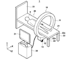
以下、図面を参照して本発明の放射線CT撮影装置の第1の実施形態について説明する。図1は本放射線CT撮影装置1の概略構成を示す斜視図である。
Hereinafter, a first embodiment of a radiation CT imaging apparatus of the present invention will be described with reference to the drawings. FIG. 1 is a perspective view showing a schematic configuration of the radiation
本放射線CT撮影装置1は、図1に示すように、放射線を射出する複数の放射線源とその放射線源から射出され、被写体5を通過した放射線を検出する複数の放射線検出器とが一体的に設けられた固定ガントリ11を有する可搬型撮影部10、被写体5が設置される設置台20と、可搬型撮影部10における放射線検出器によって検出された放射線画像信号に基づいて被写体5の断層画像を生成して表示する画像信号処理部30とを備えている。
As shown in FIG. 1, the radiation
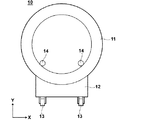
図2に、可搬型撮影部10のX−Y平面図を示す。図1および図2に示すように、可搬型撮影部10は、複数の放射線源および複数の放射線検出器が内部に設けられた固定ガントリ11と、固定ガントリ11を支持する支持台12と、支持台12に取り付けられたキャスタ部13とを備えている。
FIG. 2 shows an XY plan view of the
図3に、固定ガントリ11の内部の概略構成図を示す。固定ガントリ11は、図3に示すように、円筒形状の筐体11aを有し、その筐体11aの半円周部分の内部に複数の放射線源11bが、中心軸方向に放射線を射出するように設けられている。また、筐体11aの残りの半円周部分の内部には、放射線源11bに対向した位置に複数の放射線検出器11cが設けられている。
FIG. 3 shows a schematic configuration diagram of the inside of the
固定ガントリ11は、回転機構を有することなく、支持台12に固定して設置されている。そして、支持台12に設けられたキャスタ部13により固定ガントリ11および支持台12が搬送可能に構成されている。
The
固定ガントリ11の各放射線源11bは、高速スイッチング型の微小放射線源であり、電界放射型微小電子源を用いたものである。そして、図示省略した制御部により制御され、たとえば、図3に示す矢印方向に順番に切り替えられ、固定ガントリ11の中心軸に向かって、すなわち被写体5の方向に放射線Lを射出するものである。なお、各放射線源11bから射出される放射線Lは、図3に示すようにファンビームであることが望ましい。また、各放射線源11bは、1つずつ切り替えるようにしてもよいし、複数個ずつ切り替えるようにしてもよい。複数個ずつ切り替える場合には、同時に駆動される放射線源11bから射出された放射線が放射線検出器11cの検出面において重ならないように切り替えられる。そして、各放射線源11bから射出された放射線は、被写体5を透過して各放射線源11bに対向する位置に設けられた放射線検出器11cによって検出される。そして、各放射線検出器11cによって検出された放射線画像信号は、順次画像信号処理部30に出力される。放射線検出器11cは、半導体により放射線を検出するものであり、従来のものを利用することができるので、詳細な説明は省略する。なお、放射線検出器11cは、固定ガントリ11の中心軸が延びる方向(Z方向)に複数列設けるようにしてもよい。なお、その場合には、各放射線11bから射出される放射線の照射範囲は、複数列の放射線検出器11cの検出面の範囲をカバーするものとする。
Each
また、本実施形態の固定ガントリ11においては、放射線源11bと放射線検出器11cとをそれぞれ半周に跨って設けるようにしたが、放射線源11と放射線検出器11cとを両方とも全周に跨って設けるようにしてもよい。
Further, in the fixed
また、図2に示すように、固定ガントリ11の内側の円筒面上には、回転可能な球状のボール部材14が設けられている。このボール部材14は、固定ガントリ11の円筒内側を設置台20が通過する際、設置台20の設置板21を保持するとともに、固定ガントリ11と設置台20との摩擦を小さくして固定ガントリ11の搬送を滑らかにするために設けられたものである。また、ボール部材14は、後述する設置台20の溝部21aに嵌合するものである。なお、本実施形態においては、球状のボール部材を用いるようにしたが、固定ガントリ11と設置台20との摩擦を小さくして固定ガントリ11の搬送を滑らかにするものであればこれに限らず、たとえば、ローラ部材を利用するようにしてもよい。
As shown in FIG. 2, a rotatable
画像信号処理部30は、固定ガントリ11の各放射線検出器11cから出力された放射線画像信号が入力され、その放射線画像信号に基づいて被写体5の断層画像を生成する断層画像生成部を備えている。断層画像生成部は、放射線源11bと放射線検出器11cの幾何学的レイアウトに即したアルゴリズムで断層画像を生成するものである。そして、断層画像生成部において生成された断層画像を表す信号はモニタ装置31に出力され、モニタ装置31により被写体5の断層画像が表示される。
The image
設置台20は、被写体5が設置される設置板21と、設置板の下面に取り付けられた脚部22と、脚部22とは反対側の設置板21の端を支持する支持板23とを備えている。
The installation table 20 includes an
脚部22は、軸22aに回動可能に設けられており、設置板21の下面側に折りたたみ可能に構成されている。
The
また、設置板21の下面には、図4に示すように、溝部21aが設置板21の長手方向(図1および図4のZ方向)に延設されている。この溝部21aは、可搬型撮影部10のボール部材14が勘合するように形成されている。
Further, as shown in FIG. 4, a
また、設置板21は、放射線の吸収率が低い材料から形成することが望ましく、たとえば、木、アルミニウム、カーボン、炭素繊維強化樹脂などから形成することが望ましい。なお、放射線の吸収率が低い材料とは、原子番号の小さい物質から構成され、密度が小さい材料である。すなわち、線減弱係数が小さい材料であり、たとえば、線減弱係数がアルミニウム以下の材料を利用することが望ましい。
The
次に、第1の実施形態の放射線CT撮影装置1の作用について説明する。
Next, the operation of the radiation
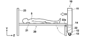
まず、図5Aに示すように、設置台20の設置板21上に被写体5が設置される。そして、可搬型撮影部10がキャスタ部13を用いて設置台20の近くまで搬送される。そして、可搬型撮影部10は、固定ガントリ11の円筒内側を設置板21が通過するように設置台20の脚部22側の方から搬送される。
First, as shown in FIG. 5A, the
そして、このとき固定ガントリ11の内側の円筒面上に設けられたボール部材14と設置板21の溝部21aとが嵌合するように可搬型撮影部10の位置が調整され、ボール部材14と溝部21aとが嵌合した状態で、可搬型撮影部10は、図5Aに示す矢印方向(設置台20の長手方向)に搬送される。そして、このとき設置台20の脚部22は、設置板21の下面側、すなわち図5Aに示す点線矢印方向に折りたたまれ、設置板21は可搬型撮影部10のボール部材14によって保持される。
At this time, the position of the portable photographing
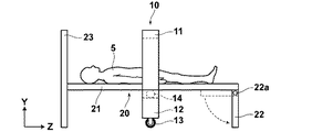
そして、図5Bに示すように、可搬型撮影部10は、被写体5の所望の撮影部位までさらに搬送される。そして、可搬型撮影部10が被写体5の所望の撮影部位まで搬送されると、被写体5の断層画像の撮影が開始される。具体的には、図示省略した制御部により放射線源11bが制御され、各放射線源11bが順番に切り替えられて放射線が射出され、被写体5に照射される。各放射線源11bから射出された放射線は、被写体5を透過して各放射線源11bに対向する位置に設けられた放射線検出器11cによって検出される。そして、各放射線検出器11cによって検出された放射線画像信号は、順次画像信号処理部30に出力される。
Then, as shown in FIG. 5B, the
そして、画像信号処理部30の断層画像生成部において、入力された放射線画像信号に基づいて断層画像を表す画像信号が生成され、その画像信号はモニタ装置31に出力され、モニタ装置31は入力された画像信号に基づいて被写体5の断層画像を診断画像として表示する。
Then, in the tomographic image generation unit of the image
そして、被写体5の所定の撮影部位の断層画像が撮影された後、再び可搬型撮影部10がさらに図5Aの矢印方向に搬送され、被写体5の次の断面画像の撮影が開始される。ここで、可搬型撮影部10は、上述したように固定ガントリ11のボール部材14と設置板21の溝部21aとが嵌合した状態で搬送されるので、図1におけるX−Y面上における被写体5に対する可搬型撮影部10の位置ずれを生じることなく搬送可能である。すなわち、可搬型撮影部10を搬送して各位置で撮影された断層画像の位置合わせを行うことができる。
Then, after a tomographic image of a predetermined imaging region of the subject 5 is captured, the
そして、可搬型撮影部10がさらに搬送されるとともに、順次所望の位置で被写体5の断層画像が撮影され、被写体5の複数枚の断層画像が取得されるとともに、モニタ装置31に表示される。
The
なお、上記第1の実施形態の放射線CT撮影装置においては、可搬型撮影部10と設置台20との摩擦を小さくして固定ガントリ11の搬送を滑らかにするために、固定ガントリ11の円筒内側の面にボール部材14を設けるようにしたが、これに限らず、たとえば、図6に示すように、設置台20の設置板21の下面に転がり部材24を長手方向について多数設けるようにしてもよい。転がり部材24としては回転可能なローラでもよいし、回転可能なボール部材でもよい。そして、このとき固定ガントリ11の円筒内側に、転がり部材24が嵌合するような溝部を形成するようにしてもよい。
In the radiation CT imaging apparatus of the first embodiment, the inside of the fixed
また、上記第1の実施形態の放射線CT撮影装置においては、被写体5の断層画像の位置合わせを行うために、設置台20の設置板21の下面または固定ガントリ11の円筒内側の面に溝部を設けるようにしたが、これに限らず、たとえば、図7に示すように、設置台20が設置される室内の床面に、可搬型撮影部10のキャスタ部13が嵌合する床面溝部40を設置板21の長手方向に延設するようにしてもよい。可搬型撮影部10のキャスタ部13を床面溝部40に嵌合させた状態で可搬型撮影部10を搬送することによって、図7におけるX−Y面上における被写体5に対する可搬型撮影部10の位置ずれを生じることなく搬送することができ、可搬型撮影部10の搬送にともなって各位置で撮影された断層画像の位置合わせを行うことができる。
In the radiation CT imaging apparatus of the first embodiment, a groove is formed on the lower surface of the
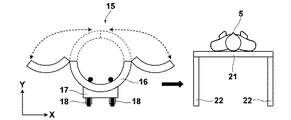
また、上記第1の実施形態の放射線CT撮影装置においては、設置台20の脚部22を折りたたむことによって固定ガントリ11の円筒内側を設置板21が通過できるようにしたが、これに限らず、たとえば、図8に示すように、撮影本体部15の固定ガントリ16の上側部分を2つに分割し、その分割部分を円筒外側に開くことができるとともに、円筒内側に向けて閉じることができるように構成するようにしてもよい。そして、図8に示すように、固定ガントリ16の分割部分を円筒外側に開いた状態で矢印方向に搬送することによって撮影本体部15を設置板21の下側に設置し、その後、分割部分を円筒内側に再び閉じて断層画像の撮影を行うようにすればよい。なお、固定ガントリ16は、支持台17に設置され、支持台17には、撮影本体部15を図8の矢印方向に搬送可能なキャスタ部18が設けられている。
Further, in the radiation CT imaging apparatus of the first embodiment, the
次に、本発明の放射線CT撮影装置の第2の実施形態について説明する。 Next, a second embodiment of the radiation CT imaging apparatus of the present invention will be described.
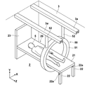
第1の実施形態の放射線CT撮影装置1においては、可搬型撮影部10にキャスタ部13を設けることによって固定ガントリ11を搬送可能にしたが、第2の実施形態の放射線CT撮影装置2は、図9に示すように、撮影本体部50の固定ガントリ51にアーム部材52を設け、このアーム部材52を移動させることによって固定ガントリ51を搬送可能にしたものである。
In the radiation
より具体的には、アーム部材52は、その一端が固定ガントリ51に接続され、他端がレール部3aに移動可能に保持されている。レール部3aは、設置台20が設置される室内の天井3に設置台20の長手方向に延設されている。
More specifically, the
そして、第2の実施形態の放射線CT撮影装置2においては、天井3に設けられたレール部3aに沿ってアーム部材52が搬送されることによって固定ガントリ51が設置台20の長手方向に搬送される。
And in the radiation
そして、上記第1の実施形態の放射線CT撮影装置と同様に、撮影本体部50の搬送にともなって、順次被写体5の断層画像の撮影が行われる。
As in the radiation CT imaging apparatus of the first embodiment, tomographic images of the subject 5 are sequentially captured as the imaging
その他の構成および作用については、上記第2の実施形態の放射線CT撮影装置と同様である。 Other configurations and operations are the same as those of the radiation CT imaging apparatus of the second embodiment.
1,2 放射線CT撮影装置
3 天井
3a レール部
5 被写体
10 可搬型撮影部
11 固定ガントリ
11a 筐体
11b 放射線源
11c 放射線検出器
12 支持台
13 キャスタ部
14 ボール部材
15 撮影本体部
16 固定ガントリ
17 支持台
18 キャスタ部
20 設置台
21 設置板
21a 溝部
22 脚部
22a 軸
23 支持板
24 転がり部材
30 画像信号処理部
31 モニタ装置
40 床面溝部
50 撮影本体部
51 固定ガントリ
52 アーム部材
1, 2 Radiation
Claims (8)
前記複数の放射線源と前記複数の放射線検出器とが一体的に設けられた撮影本体部に、該撮影本体部を搬送可能にする搬送部材が設けられていることを特徴とする放射線CT撮影装置。 A plurality of radiation sources, a plurality of radiation detectors provided at positions opposed to the respective radiation sources, detecting radiation emitted sequentially from the respective radiation sources and transmitted through the subject, and detected by the plurality of radiation detectors A radiation CT imaging apparatus comprising: a tomographic image generation unit configured to generate a tomographic image of the subject based on the radiographic image signal,
A radiation CT imaging apparatus comprising: an imaging main body unit in which the plurality of radiation sources and the plurality of radiation detectors are integrally provided; .
前記撮影本体部が筒形状に構成されており、
該筒形状の撮影本体部の筒内側を前記設置台が通過する際、前記設置台の脚部が折りたたまれるものであるとともに、前記設置板が前記撮影本体部の内側の筒面上に設置されるものであることを特徴とする請求項1記載の放射線CT撮影装置。 An installation base having an installation plate on which the subject is installed and a leg attached to a lower surface of the installation plate;
The photographing main body is configured in a cylindrical shape,
When the installation table passes through the cylindrical inner side of the tube-shaped imaging main body, the legs of the installation table are folded, and the installation plate is installed on the inner cylindrical surface of the imaging main body. The radiation CT imaging apparatus according to claim 1, wherein
前記設置板の下面に、前記転がり部材が嵌合する溝部が前記設置板の長手方向に延設されていることを特徴する請求項2記載の放射線CT撮影装置。 While holding the installation plate on the inner cylindrical surface of the photographing main body, a rotatable rolling member is provided,
The radiation CT imaging apparatus according to claim 2, wherein a groove portion into which the rolling member is fitted is extended on a lower surface of the installation plate in a longitudinal direction of the installation plate.
前記複数の放射線源と前記複数の放射線検出器とが一体的に設けられた撮影本体部に一端が接続され、他端が移動可能に保持されるアーム部材と、該アーム部材を移動可能に支持するレール部とを備えたことを特徴とする放射線CT撮影装置。 A plurality of radiation sources, a plurality of radiation detectors provided at positions opposed to the respective radiation sources, detecting radiation emitted sequentially from the respective radiation sources and transmitted through the subject, and detected by the plurality of radiation detectors A radiation CT imaging apparatus comprising: a tomographic image generation unit configured to generate a tomographic image of the subject based on the radiographic image signal,
An arm member having one end connected to an imaging main body unit integrally provided with the plurality of radiation sources and the plurality of radiation detectors, the other end being movably supported, and the arm member being movably supported A radiation CT imaging apparatus, comprising:
Priority Applications (2)
| Application Number | Priority Date | Filing Date | Title |
|---|---|---|---|
| JP2008316353A JP2010136902A (en) | 2008-12-12 | 2008-12-12 | Radiation ct apparatus |
| US12/654,142 US20100150304A1 (en) | 2008-12-12 | 2009-12-11 | Radiation CT imaging apparatus |
Applications Claiming Priority (1)
| Application Number | Priority Date | Filing Date | Title |
|---|---|---|---|
| JP2008316353A JP2010136902A (en) | 2008-12-12 | 2008-12-12 | Radiation ct apparatus |
Publications (2)
| Publication Number | Publication Date |
|---|---|
| JP2010136902A true JP2010136902A (en) | 2010-06-24 |
| JP2010136902A5 JP2010136902A5 (en) | 2011-09-15 |
Family
ID=42240528
Family Applications (1)
| Application Number | Title | Priority Date | Filing Date |
|---|---|---|---|
| JP2008316353A Abandoned JP2010136902A (en) | 2008-12-12 | 2008-12-12 | Radiation ct apparatus |
Country Status (2)
| Country | Link |
|---|---|
| US (1) | US20100150304A1 (en) |
| JP (1) | JP2010136902A (en) |
Cited By (2)
| Publication number | Priority date | Publication date | Assignee | Title |
|---|---|---|---|---|
| JP2014180416A (en) * | 2013-03-19 | 2014-09-29 | Sumitomo Heavy Ind Ltd | Charged particle beam therapeutic apparatus |
| JP2015057606A (en) * | 2012-03-09 | 2015-03-26 | 同方威視技術股▲分▼有限公司 | Apparatus and method for ray scanning imaging |
Families Citing this family (7)
| Publication number | Priority date | Publication date | Assignee | Title |
|---|---|---|---|---|
| WO2011106433A1 (en) | 2010-02-24 | 2011-09-01 | Accuray Incorporated | Gantry image guided radiotherapy system and related treatment delivery methods |
| US9687200B2 (en) * | 2010-06-08 | 2017-06-27 | Accuray Incorporated | Radiation treatment delivery system with translatable ring gantry |
| US8536547B2 (en) | 2011-01-20 | 2013-09-17 | Accuray Incorporated | Ring gantry radiation treatment delivery system with dynamically controllable inward extension of treatment head |
| DE102012213875B4 (en) | 2012-08-06 | 2019-12-24 | Siemens Healthcare Gmbh | Supply unit for a movable gantry |
| CN103499593A (en) * | 2013-09-23 | 2014-01-08 | 深圳先进技术研究院 | Computed tomography scanning system |
| US10034642B1 (en) * | 2017-12-22 | 2018-07-31 | The Parking Space, LLC | Wheel alignment guide for medical equipment and method of use |
| CN116509427A (en) * | 2023-07-04 | 2023-08-01 | 深圳市宝润科技有限公司 | Movable cone beam scanner system |
Family Cites Families (5)
| Publication number | Priority date | Publication date | Assignee | Title |
|---|---|---|---|---|
| US4741015A (en) * | 1986-12-05 | 1988-04-26 | B. C. Medical Compagnie Limitee | Universal X-ray unit |
| US6343108B1 (en) * | 1999-06-18 | 2002-01-29 | Philips Medical Systems (Cleveland), Inc. | Cone beam scanner using oblique surface reconstructions |
| CN100482165C (en) * | 2002-06-11 | 2009-04-29 | 分离成像有限责任公司 | Cantilevered gantry apparatus for X-ray imaging |
| US7570734B2 (en) * | 2003-07-25 | 2009-08-04 | J. Morita Manufacturing Corporation | Method and apparatus for X-ray image correction |
| US7280631B2 (en) * | 2003-11-26 | 2007-10-09 | General Electric Company | Stationary computed tomography system and method |
-
2008
- 2008-12-12 JP JP2008316353A patent/JP2010136902A/en not_active Abandoned
-
2009
- 2009-12-11 US US12/654,142 patent/US20100150304A1/en not_active Abandoned
Cited By (2)
| Publication number | Priority date | Publication date | Assignee | Title |
|---|---|---|---|---|
| JP2015057606A (en) * | 2012-03-09 | 2015-03-26 | 同方威視技術股▲分▼有限公司 | Apparatus and method for ray scanning imaging |
| JP2014180416A (en) * | 2013-03-19 | 2014-09-29 | Sumitomo Heavy Ind Ltd | Charged particle beam therapeutic apparatus |
Also Published As
| Publication number | Publication date |
|---|---|
| US20100150304A1 (en) | 2010-06-17 |
Similar Documents
| Publication | Publication Date | Title |
|---|---|---|
| JP2010136902A (en) | Radiation ct apparatus | |
| JP4508789B2 (en) | X-ray equipment | |
| US20200245958A1 (en) | Radiological imaging system occupying a reduced space | |
| US8548117B2 (en) | Semicircular inversed offset scanning for enlarged field of view 3D | |
| JP2016028256A (en) | Method and device for multi-camera x-ray flat panel detector | |
| US20070025522A1 (en) | Methods and apparatus for small footprint imaging system | |
| US10136867B2 (en) | Radiological imaging system with improved internal movement | |
| JP4559312B2 (en) | Radiography equipment | |
| US10729394B1 (en) | Portable scanning system for imaging patients | |
| JP2009233158A (en) | Radiological diagnostic apparatus and radiography method | |
| JP5881006B2 (en) | Tomography equipment | |
| JP2006288910A (en) | Tomographic apparatus | |
| EP3195803B1 (en) | X-ray table and x-ray system comprising same | |
| JP2014023611A (en) | Radiographic apparatus, control method, and program | |
| JP2006280927A (en) | Tomographic apparatus and high-speed volume scanning method for inspection range using the tomographic apparatus | |
| JP2020010886A (en) | Radiographic apparatus, method for controlling the same and program | |
| JP5758187B2 (en) | X-ray CT system | |
| KR20120090290A (en) | Medical radiography system | |
| JP2023014757A (en) | Radiation detector and radiographic device | |
| JP2010259498A (en) | Medical image diagnostic apparatus | |
| JP6255743B2 (en) | Radiation tomography apparatus and radiation tomography system | |
| JP2006280782A (en) | Radiographic imaging apparatus | |
| JP2023014759A (en) | Radiation detector and radiographic device | |
| JP2010082319A (en) | X-ray apparatus and bed device | |
| JP5999516B2 (en) | Radiography equipment |
Legal Events
| Date | Code | Title | Description |
|---|---|---|---|
| RD15 | Notification of revocation of power of sub attorney |
Free format text: JAPANESE INTERMEDIATE CODE: A7435 Effective date: 20110519 |
|
| A521 | Request for written amendment filed |
Free format text: JAPANESE INTERMEDIATE CODE: A523 Effective date: 20110802 |
|
| A621 | Written request for application examination |
Free format text: JAPANESE INTERMEDIATE CODE: A621 Effective date: 20110802 |
|
| A762 | Written abandonment of application |
Free format text: JAPANESE INTERMEDIATE CODE: A762 Effective date: 20130205 |
|
| A977 | Report on retrieval |
Free format text: JAPANESE INTERMEDIATE CODE: A971007 Effective date: 20130228 |
