JP2010131663A - Manufacturing method of bushing with oil reserving blind groove for chain - Google Patents
Manufacturing method of bushing with oil reserving blind groove for chain Download PDFInfo
- Publication number
- JP2010131663A JP2010131663A JP2008312194A JP2008312194A JP2010131663A JP 2010131663 A JP2010131663 A JP 2010131663A JP 2008312194 A JP2008312194 A JP 2008312194A JP 2008312194 A JP2008312194 A JP 2008312194A JP 2010131663 A JP2010131663 A JP 2010131663A
- Authority
- JP
- Japan
- Prior art keywords
- blind
- pin
- hollow die
- inner peripheral
- steel material
- Prior art date
- Legal status (The legal status is an assumption and is not a legal conclusion. Google has not performed a legal analysis and makes no representation as to the accuracy of the status listed.)
- Granted
Links
- 238000004519 manufacturing process Methods 0.000 title claims abstract description 33
- XBWAZCLHZCFCGK-UHFFFAOYSA-N 7-chloro-1-methyl-5-phenyl-3,4-dihydro-2h-1,4-benzodiazepin-1-ium;chloride Chemical compound [Cl-].C12=CC(Cl)=CC=C2[NH+](C)CCN=C1C1=CC=CC=C1 XBWAZCLHZCFCGK-UHFFFAOYSA-N 0.000 claims abstract description 94
- 229910000831 Steel Inorganic materials 0.000 claims abstract description 89
- 239000010959 steel Substances 0.000 claims abstract description 89
- 230000002093 peripheral effect Effects 0.000 claims abstract description 62
- 239000000463 material Substances 0.000 claims abstract description 53
- 238000003825 pressing Methods 0.000 claims description 29
- 230000015572 biosynthetic process Effects 0.000 claims 1
- 238000005299 abrasion Methods 0.000 abstract 1
- 239000003921 oil Substances 0.000 description 67
- 238000000034 method Methods 0.000 description 8
- 230000000694 effects Effects 0.000 description 7
- 239000010687 lubricating oil Substances 0.000 description 3
- 239000002184 metal Substances 0.000 description 3
- 229910052751 metal Inorganic materials 0.000 description 3
- XEEYBQQBJWHFJM-UHFFFAOYSA-N Iron Chemical compound [Fe] XEEYBQQBJWHFJM-UHFFFAOYSA-N 0.000 description 2
- 238000007796 conventional method Methods 0.000 description 2
- 238000010586 diagram Methods 0.000 description 2
- 230000007774 longterm Effects 0.000 description 2
- 238000009825 accumulation Methods 0.000 description 1
- 239000003245 coal Substances 0.000 description 1
- 238000002485 combustion reaction Methods 0.000 description 1
- 230000003247 decreasing effect Effects 0.000 description 1
- 230000007547 defect Effects 0.000 description 1
- 229910052742 iron Inorganic materials 0.000 description 1
- 230000001050 lubricating effect Effects 0.000 description 1
- 239000000843 powder Substances 0.000 description 1
- 230000000717 retained effect Effects 0.000 description 1
Images

Landscapes
- Sliding-Contact Bearings (AREA)
Abstract
Description
本発明は、チェーンの連結ピンに対して回動自在に嵌挿するブシュとして好適に用いられるチェーン用ブシュに関するものであって、特に、潤滑油の油溜まりとなる油溜まり用盲溝を内周面側母線方向に多数形成したチェーン用油溜まり盲溝付ブシュの製造方法に関するものである。 The present invention relates to a chain bushing that is preferably used as a bushing that is rotatably inserted into a connecting pin of a chain, and in particular, an oil reservoir blind groove that serves as an oil reservoir for lubricating oil is provided on the inner periphery. The present invention relates to a method for producing a chain oil sump blind bush having a large number formed in the surface-side bus direction.
従来、円筒軸受は、その内周面内にシャフト、ピン等の回転軸を挿入され、回転軸の軸受体、チェーンのブシュ等の滑り軸受として使用されている。
そして、このような円筒軸受には、軸受面となる内周面とシャフト、ピン等との潤滑性を向上させるために、その内周面母線方向と平行な潤滑油の油溜まりとなる有底の溝、すなわち、油溜まり用盲溝が内周面側に多数形成されている。
Conventionally, a cylindrical bearing has a rotating shaft such as a shaft or a pin inserted in an inner peripheral surface thereof, and is used as a sliding bearing such as a bearing body of the rotating shaft or a bush of a chain.
In such a cylindrical bearing, in order to improve the lubricity between the inner peripheral surface serving as the bearing surface and the shaft, pins, etc., a bottomed bottom that serves as a reservoir for lubricating oil parallel to the direction of the inner peripheral surface bus In other words, many oil reservoir blind grooves are formed on the inner peripheral surface side.
このような円筒軸受を製造する従来の方法として、図6に示すような複数の盲溝付け用突起511とスリット512を有した中空状ダイピン510と、円筒鋼材501の端部を押圧する盲溝付け用ポンチ520に同心状に一体的に備えられたセンターピン530を用いた方法がある。
As a conventional method for manufacturing such a cylindrical bearing, a
すなわち、円筒鋼材501は、図7の(a)に示すように、中空状ダイピン510を内部に設けている盲溝付け用ダイ540とセンターピン530の間に配置され、盲溝付け用ポンチ520を前進させると、図7の(b)に示すように、円筒鋼材501は、その端部が盲溝付け用ポンチ520に当接して前進して、盲溝付け用ダイ540に押し込まれ、盲溝付け用ダイ540内に固定配置されている中空状ダイピン510が円筒鋼材501の内部に差し込まれる。
That is, as shown in FIG. 7A, the
また、盲溝付け用ポンチ520に備えられたセンターピン530も、盲溝付け用ポンチ520の前進にともなって、中空状ダイピン510の中空部に押し込まれ、中空状ダイピン510を拡径させて、円筒鋼材501の内周面に盲溝付け用突起511を圧入させる。
Further, the
さらに、盲溝付け用ポンチ520を前進させると、図7の(c)に示すように、円筒鋼材501は、センターピン530が押し込まれて拡径させた状態の中空状ダイピン510を差し込みながら前進し、円筒鋼材501の内周面502に圧入されている盲溝付け用突起511を円筒鋼材501に対して相対的に摺動させて、母線方向に沿って半円形断面を有する盲溝が刻設されて盲溝付け加工が施される。
When the
その後、前述した盲溝付け用ポンチ520を後退させると、図7の(d)に示すように、センターピン530は後退して、中空状ダイピン510を元の状態に縮径して、円筒鋼材501から抜き取られる。次いで、図7の(e)に示すように、ストリッパ550を前進させると、円筒鋼材501が盲溝付け用ダイ540および中空状ダイピン510から取り出され、換言すれば、円筒鋼材501から中空状ダイピン510が相対的に抜き取られて、複数の油溜まり用盲溝503が内周面502に刻設されたチェーン用油溜まり盲溝付ブシュ500となる(特許文献1参照)。
しかしながら、従来のような製造方法では、油溜まり用盲溝503を刻設する際にセンターピン530と中空状ダイピン510とが相互に強い押圧力で摺動するため、中空状ダイピン510の摩耗寿命が著しく低下するという問題があった。
また、中空状ダイピン510には、拡径の繰り返しによる金属疲労を生じるが、センターピン530を通過させる中空部分が不可欠な形状となっているため、中空状ダイピン510の強度を増すことが困難であるという問題があった。
他方、センターピン530も、中空状ダイピン510の中空部分に進入させるために、その外径が小さくならざるを得ず、しばしば破損するという問題もあった。
However, in the conventional manufacturing method, the
The
On the other hand, since the
そこで、本発明が解決しようとする課題、すなわち、本発明の目的は、上述したような従来技術の問題点を解決するものであって、油溜まり用盲溝を刻設するセンターピンと中空状ダイピンの長期にわたる摩耗損傷を抑制して優れた疲労強度を発揮できるとともに、薄肉の円筒鋼材であっても油溜まり用盲溝を高精度に刻設できるチェーン用油溜まり盲溝付ブシュの製造方法を提供することである。 Therefore, the problem to be solved by the present invention, that is, the object of the present invention is to solve the above-mentioned problems of the prior art, and a center pin and a hollow die pin for engraving an oil sump blind groove. A manufacturing method of oil sump blind groove bushing for chains that can exhibit excellent fatigue strength by suppressing wear damage over a long period of time, and can engrave blind grooves for oil sump with high precision even for thin cylindrical steel materials Is to provide.
本請求項1に係る発明は、多数の盲溝付け部材を先端外周部の保持孔に出没可能に保持した中空状ダイピンと、該中空状ダイピンに当て止めされ保持孔に保持された盲溝付け部材を外周側に突出させて押圧するセンターピンと、該センターピンに同心円状に遊嵌されてピン長手方向に相対的に摺動する盲溝付け用ポンチと、該盲溝付け用ポンチを受け入れる盲溝付け用ダイとを用いて円筒鋼材の内周面側母線方向に多数の油溜まり盲溝を形成するチェーン用油溜まり盲溝付ブシュの製造方法であって、前記円筒鋼材の一端が前記盲溝付け用ダイに内包された中空状ダイピンの先端外周部に被嵌された後、前記円筒鋼材の他端から一端に向けて挿し入れた前記センターピンが前記中空状ダイピンの先端内周部に差し込まれた状態で前記盲溝付け部材を中空状ダイピンの保持孔から突出して円筒鋼材の内周面に押し付け、次いで、前記センターピンに遊嵌された盲溝付け用ポンチが前記円筒鋼材の他端を押圧した状態で盲溝付け用ダイ内に押し込まれて前記円筒鋼材の内周面を中空状ダイピンの保持孔から突出した盲溝付け部材に対して摺動させながら多数の油溜まり盲溝を形成することにより、前記課題を解決するものである。 The invention according to claim 1 is a hollow die pin in which a number of blind grooved members are held so as to be able to protrude and retract in a holding hole at the outer periphery of the tip, and blind grooved in which the hollow die pin is held against and held in the holding hole. A center pin that protrudes and presses the member toward the outer peripheral side, a blind groove punch that is loosely fitted concentrically with the center pin and slides relatively in the longitudinal direction of the pin, and a blind that receives the blind groove punch A chain oil sump blind grooved bushing for forming a number of oil sump blind grooves in the direction of the inner circumferential surface of the cylindrical steel using a grooving die, wherein one end of the cylindrical steel material is the blind The center pin inserted into the hollow die pin from one end to the other after being fitted on the tip outer periphery of the hollow die pin contained in the grooving die is placed on the tip inner periphery of the hollow die pin. Blind groove in the inserted state The material protrudes from the holding hole of the hollow die pin and is pressed against the inner peripheral surface of the cylindrical steel material, and then the blind groove is punched with the blind groove punch that is loosely fitted to the center pin pressing the other end of the cylindrical steel material. By forming a large number of oil sump blind grooves while sliding the inner peripheral surface of the cylindrical steel material against the blind grooved member protruding from the holding hole of the hollow die pin by being pushed into the die for use, It is a solution.
本請求項2に係る発明は、請求項1に記載されたチェーン用油溜まり盲溝付ブシュの製造方法の構成に加えて、前記センターピンが、前記中空状ダイピンの先端内周部に差し込まれて当て止めされるダイピン係合用段部を備え、該センターピンが当て止めされた位置で、中空状ダイピンの保持孔から盲溝付け部材が突出するようになっていることにより、前記課題をさらに解決するものである。 In the invention according to claim 2, in addition to the structure of the manufacturing method of the oil sump blind grooved bush for the chain according to claim 1, the center pin is inserted into the inner periphery of the tip of the hollow die pin. A die groove engaging step portion to be abutted and a blind grooved member protruding from a holding hole of the hollow die pin at a position where the center pin is abutted. It is a solution.
本請求項3に係る発明は、請求項1または請求項2に記載されたチェーン用油溜まり盲溝付ブシュの製造方法の構成に加えて、前記センターピンの後端部に設けられてセンターピンを中空状ダイピンの先端内周部に向けて押圧する第1押圧手段と前記盲溝付け用ポンチをセンターピンに摺動させて盲溝付け用ポンチのみを円筒鋼材の他端に向けて押圧する第2押圧手段とが、それぞれ単独で押圧自在となるように設けられていることにより、前記課題をさらに解決するものである。 According to a third aspect of the present invention, in addition to the structure of the manufacturing method of the oil sump blind grooved bush for the chain described in the first or second aspect, the center pin is provided at the rear end portion of the center pin. The first pressing means for pressing the die toward the inner peripheral portion of the tip of the hollow die pin and the blind groove punch are slid on the center pin and only the blind groove punch is pressed toward the other end of the cylindrical steel material. The second pressing means is provided so as to be independently pressable, thereby further solving the problem.
本請求項4に係る発明は、請求項1乃至請求項3のいずれかに記載されたチェーン用油溜まり盲溝付ブシュの製造方法の構成に加えて、前記盲溝付け部材が、鋼球であることにより、前記課題をさらに解決するものである。 In addition to the structure of the manufacturing method of the oil sump blind grooved bush for the chain according to any one of claims 1 to 3, the blind grooved member is a steel ball. The present invention further solves the above problems.
本請求項5に係る発明は、請求項1乃至請求項4のいずれかに記載されたチェーン用油溜まり盲溝付ブシュの製造方法の構成に加えて、前記中空状ダイピンの先端内周部に前記盲溝付け部材の内周側への脱落を阻止する抜け止めピンが、センターピン方向に付勢されて出没可能に設けられていることにより、前記課題をさらに解決するものである。 In addition to the structure of the method for producing the oil sump blind grooved bush for the chain according to any one of claims 1 to 4, the invention according to claim 5 is provided at the inner peripheral portion of the tip of the hollow die pin. The above-described problem is further solved by providing a retaining pin for preventing the blind grooved member from falling off toward the inner peripheral side so as to be urged toward and away from the center pin.
本発明のチェーン用油溜まり盲溝付ブシュの製造方法は、多数の盲溝付け部材を先端外周部の保持孔に出没可能に保持した中空状ダイピンと、該中空状ダイピンに当て止めされ保持孔に保持された盲溝付け部材を外周側に突出させて押圧するセンターピンと、該センターピンに同心円状に遊嵌されてピン長手方向に相対的に摺動する盲溝付け用ポンチと、該盲溝付け用ポンチを受け入れる盲溝付け用ダイとを用いて円筒鋼材の内周面側母線方向に多数の油溜まり盲溝を形成することにより、チェーンの連結ピンに対して回動自在に嵌挿するブシュとして好適に用いられるとともに、以下のような特有の効果を奏することができる。 The manufacturing method of the oil sump blind groove bush according to the present invention includes a hollow die pin that holds a large number of blind groove members in a retaining hole at the outer periphery of the tip, and a retaining hole that is held against the hollow die pin. A center pin that projects and presses the blind grooved member held on the outer peripheral side, a blind grooved punch that is loosely fitted to the center pin and slides relatively in the longitudinal direction of the pin, and the blind pin A large number of oil reservoir blind grooves are formed in the direction of the inner peripheral surface of the cylindrical steel material using a blind groove die that receives the groove punch, and is rotatably inserted into the connecting pin of the chain. While being suitably used as a bush, the following specific effects can be achieved.
すなわち、本請求項1に係る発明のチェーン用油溜まり盲溝付ブシュの製造方法は、円筒鋼材の一端が盲溝付け用ダイに内包された中空状ダイピンの先端外周部に被嵌された後、円筒鋼材の他端から一端に向けて挿し入れたセンターピンが中空状ダイピンの先端内周部に差し込まれた状態で盲溝付け部材を中空状ダイピンの保持孔から突出して円筒鋼材の内周面に押し付け、次いで、センターピンに遊嵌された盲溝付け用ポンチが円筒鋼材の他端を押圧した状態で盲溝付け用ダイ内に押し込まれて円筒鋼材の内周面を中空状ダイピンの保持孔から突出した盲溝付け部材に対して摺動させながら多数の油溜まり盲溝を形成することにより、円筒鋼材の内周面に油溜まり用盲溝を刻設する際に、盲溝付け部材が円筒鋼材に対して相対的に移動して摺動するのみで、中空状ダイピンは変形せず摺動もしないため、中空状ダイピンの長期にわたる摩耗損傷を抑制して優れた疲労強度を発揮できるとともに、油溜まり用盲溝を高精度に刻設できる。 That is, in the manufacturing method of the oil sump blind blind bush for the chain according to the first aspect of the invention, after one end of the cylindrical steel material is fitted on the outer periphery of the tip of the hollow die pin enclosed in the blind groove die. The blind groove member protrudes from the holding hole of the hollow die pin with the center pin inserted from the other end of the cylindrical steel material toward the one end into the hollow inner end of the hollow die pin. Next, the blind grooving punch loosely fitted to the center pin is pressed into the blind grooving die while pressing the other end of the cylindrical steel material, and the inner peripheral surface of the cylindrical steel material is pushed into the hollow die pin. By forming a large number of oil reservoir blind grooves while sliding against the blind groove member protruding from the holding hole, blind grooves are formed when the oil reservoir blind grooves are engraved on the inner peripheral surface of the cylindrical steel material. The member moves relative to the cylindrical steel Since the hollow die pin is not deformed and does not slide, it can exhibit excellent fatigue strength by suppressing long-term wear damage of the hollow die pin, and the oil groove blind groove is engraved with high precision it can.
そして、本請求項2に係る発明のチェーン用油溜まり盲溝付ブシュの製造方法は、請求項1に係るチェーン用油溜まり盲溝付ブシュが奏する効果に加えて、センターピンが中空状ダイピンの先端内周部に差し込まれて当て止めされるダイピン係合用段部を備え、該センターピンが当て止めされた位置で、中空状ダイピンの保持孔から盲溝付け部材が突出するようになっていることにより、円筒鋼材の内周面に油溜まり用盲溝を刻設する際に、従来のようにセンターピンと中空状ダイピンとが相互に摺動することなくセンターピンが中空状ダイピンの先端内周部に差し込まれて当て止め保持された状態となるため、センターピンの長期にわたる摩耗損傷を抑制してさらに優れた疲労強度を発揮できるとともに、油溜まり用盲溝を高精度に刻設できる。 In addition to the effect of the chain oil sump blind grooved bushing according to the first aspect, the manufacturing method of the chain oil sump blind grooved bushing according to the second aspect of the invention has the center pin of the hollow die pin. A die pin engaging step portion inserted into the inner peripheral portion of the tip and held against is provided, and the blind grooved member projects from the holding hole of the hollow die pin at the position where the center pin is held against. Thus, when the blind groove for oil sump is engraved on the inner peripheral surface of the cylindrical steel material, the center pin does not slide against each other as in the conventional case, and the center pin does not slide inside the tip end of the hollow die pin. Since it is inserted into the part and held against holding, it can suppress wear damage of the center pin for a long time and exhibit further excellent fatigue strength, and the blind groove for oil sump can be engraved with high precision That.
また、本請求項3に係る発明のチェーン用油溜まり盲溝付ブシュの製造方法は、請求項1または請求項2に係るチェーン用油溜まり盲溝付ブシュが奏する効果に加えて、センターピンの後端部に設けられてセンターピンを中空状ダイピンの先端内周部に向けて押圧する第1押圧手段と盲溝付け用ポンチをセンターピンに摺動させて盲溝付け用ポンチのみを円筒鋼材の他端に向けて押圧する第2押圧手段とが、それぞれ単独で押圧自在となるように設けられていることにより、従来の盲溝付け用ポンチやセンターピンのような拡径しながら円筒鋼材の一端を押圧して油溜まり用盲溝を刻設するものに比べて、円筒鋼材の内周面側母線方向に油溜まり用盲溝をより高精度に刻設できる。 Further, the manufacturing method of the oil sump blind grooved bush for the chain according to the third aspect of the invention is not limited to the effect of the oil sump blind grooved bush for the chain according to the first or second aspect. The first pressing means provided at the rear end and presses the center pin toward the inner periphery of the tip of the hollow die pin, and the blind groove punch is slid on the center pin so that only the blind groove punch is a cylindrical steel material. The second pressing means that presses toward the other end of the cylinder is provided so as to be able to be pressed independently, so that the cylindrical steel material while expanding the diameter like a conventional blind groove punch or center pin. The oil reservoir blind groove can be engraved with higher accuracy in the direction of the inner peripheral surface of the cylindrical steel material than the case where the oil reservoir blind groove is engraved by pressing one end of the cylinder.
また、本請求項4に係る発明のチェーン用油溜まり盲溝付ブシュの製造方法は、請求項1乃至請求項3のいずれかに係るチェーン用油溜まり盲溝付ブシュが奏する効果に加えて、盲溝付け部材が鋼球であることにより、保持孔内での移動や円筒鋼材の内周面に油溜まり用盲溝を刻設する際の摺動が円滑に行われるとともに、製造や摩耗時の交換が容易となり、油溜まり用盲溝を高精度に刻設できる。 In addition, in addition to the effect of the chain oil sump blind grooved bush according to any one of claims 1 to 3, the manufacturing method of the chain oil sump blind grooved bush according to the present invention includes: Because the blind grooved member is a steel ball, it can move smoothly in the holding hole and slide when engraving the oil retaining blind groove on the inner peripheral surface of the cylindrical steel material. The oil reservoir blind groove can be engraved with high accuracy.
また、本請求項5に係る発明のチェーン用油溜まり盲溝付ブシュの製造方法は、請求項1乃至請求項4のいずれかに係るチェーン用油溜まり盲溝付ブシュが奏する効果に加えて、中空状ダイピンの先端内周部に前記盲溝付け部材の内周側への脱落を阻止する抜け止めピンが、センターピン方向に付勢されて出没可能に設けられていることにより、盲溝付け部材が保持孔から脱落することが防止されるため、油溜まり用盲溝を欠損なく高精度に刻設できる。 In addition, in addition to the effect of the chain oil sump blind grooved bush according to any one of claims 1 to 4, the method for producing the chain oil sump blind grooved bush according to claim 5 By attaching a retaining pin that prevents the blind grooved member from falling off to the inner peripheral side at the tip inner peripheral part of the hollow die pin, the pin is biased in the direction of the center pin so that it can protrude and retract. Since the member is prevented from falling out of the holding hole, the blind groove for oil sump can be engraved with high accuracy without a defect.
本発明のチェーン用油溜まり盲溝付ブシュの製造方法は、多数の盲溝付け部材を先端外周部の保持孔に出没可能に保持した中空状ダイピンと、該中空状ダイピンに当て止めされ保持孔に保持された盲溝付け部材を外周側に突出させて押圧するセンターピンと、該センターピンに同心円状に遊嵌されてピン長手方向に相対的に摺動する盲溝付け用ポンチと、該盲溝付け用ポンチを受け入れる盲溝付け用ダイとを用いて円筒鋼材の内周面側母線方向に多数の油溜まり盲溝を形成するチェーン用油溜まり盲溝付ブシュの製造方法であって、円筒鋼材の一端が盲溝付け用ダイに内包された中空状ダイピンの先端外周部に被嵌された後、円筒鋼材の他端から一端に向けて挿し入れたセンターピンが中空状ダイピンの先端内周部に差し込まれた状態で前記盲溝付け部材を中空状ダイピンの保持孔から突出して円筒鋼材の内周面に押し付け、次いで、センターピンに遊嵌された盲溝付け用ポンチが円筒鋼材の他端を押圧した状態で盲溝付け用ダイ内に押し込まれて円筒鋼材の内周面を中空状ダイピンの保持孔から突出した盲溝付け部材に対して摺動させながら多数の油溜まり盲溝を形成し、油溜まり用盲溝を刻設するセンターピンと中空状ダイピンの長期にわたる摩耗損傷を抑制して優れた疲労強度を発揮できるとともに、薄肉の円筒鋼材であっても油溜まり用盲溝を高精度に刻設できるという効果を発揮するものであれば、その具体的な実施態様は如何なるものであっても何ら構わない。 The manufacturing method of the oil sump blind groove bush according to the present invention includes a hollow die pin that holds a large number of blind groove members in a retaining hole at the outer periphery of the tip, and a retaining hole that is held against the hollow die pin. A center pin that projects and presses the blind grooved member held on the outer peripheral side, a blind grooved punch that is loosely fitted to the center pin and slides relatively in the longitudinal direction of the pin, and the blind pin A method for producing an oil sump blind groove bush for a chain that forms a number of oil sump blind grooves in the direction of the inner peripheral surface of the cylindrical steel material using a blind groove die that receives a groove punch. The center pin inserted from the other end of the cylindrical steel material toward one end after the end of the steel material is fitted on the tip outer periphery of the hollow die pin enclosed in the blind grooving die, and the tip inner periphery of the hollow die pin In the state of being inserted into the part The grooved member protrudes from the holding hole of the hollow die pin and is pressed against the inner peripheral surface of the cylindrical steel material. Then, the blind grooved punch that is loosely fitted to the center pin presses the other end of the cylindrical steel material and is blindly grooved. A large number of oil sump blind grooves are formed while sliding the inner peripheral surface of the cylindrical steel material against the blind grooved member protruding from the holding hole of the hollow die pin by being pushed into the die for use. In addition to suppressing long-term wear damage of the center pin and hollow die pin to be engraved, excellent fatigue strength can be demonstrated, and the effect of being able to engrave the blind groove for oil sump with high precision even with a thin cylindrical steel material Any specific embodiment may be used as long as it does.
すなわち、本発明のチェーン用油溜まり盲溝付ブシュの製造方法により製造されるブシュはいかなる用途のチェーンに使用されるものであっても良く、特に鉄鉱石、石炭などを荷揚げするためのバケットチェーン、自動車などの重量物を搬送するための大荷重用チェーン、粉粒体のフローコンベヤチェーン等のチェーンにかかる荷重が大きい用途や、内燃機関のタイミングシステムに使用されるタイミングチェーン等の用途が好適である。 That is, the bush manufactured by the method for manufacturing the oil groove blind grooved bush for the chain of the present invention may be used for a chain of any application, and in particular, a bucket chain for unloading iron ore, coal, etc. Suitable for applications such as heavy-duty chains for transporting heavy objects such as automobiles, heavy loads on chains such as granular flow conveyor chains, and timing chains used in internal combustion engine timing systems It is.
以下に、本発明の実施例であるチェーン用油溜まり盲溝付ブシュの製造方法について、図面に基づいて説明する。
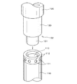
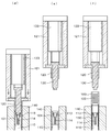
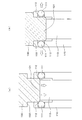
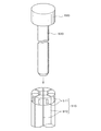
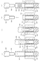
図1は、本発明で製造されるブシュの斜視図であり、図2は、本発明に使用される中空状ダイピン及びセンターピンの斜視図であり、図3は、本発明のチェーン用油溜まり盲溝付ブシュの製造方法の工程前半の動作説明図であり、図4は、本発明のチェーン用油溜まり盲溝付ブシュの製造方法の工程後半の動作説明図であり、図5は、本発明に使用される盲溝付け部材の動作説明図である。
Below, the manufacturing method of the oil sump for chains and a blind grooved bush which is an Example of this invention is demonstrated based on drawing.
FIG. 1 is a perspective view of a bush manufactured according to the present invention, FIG. 2 is a perspective view of a hollow die pin and a center pin used in the present invention, and FIG. 3 is an oil sump for a chain according to the present invention. FIG. 4 is an operation explanatory diagram of the first half of the process of the manufacturing method of the blind grooved bush, FIG. 4 is an operation explanatory diagram of the latter half of the process of the manufacturing method of the oil sump blind grooved bush of the present invention, and FIG. It is operation | movement explanatory drawing of the blind grooved member used for invention.
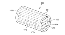
本発明で製造されるチェーン用油溜まり盲溝付ブシュ100は、図1に示すように、母線状継目がない円筒鋼材101の内周面102側、すなわち、円筒鋼材101の内周面102側母線方向に多数の油溜まり用盲溝103が形成されており、この油溜まり用盲溝103における溝長手方向の始端部103aと終端部103bが封止された溝形態となっている。
As shown in FIG. 1, a chain oil sump blind grooved
例えば、ローラーチェーンに用いる場合、盲溝付ブシュ100は、油溜まり用盲溝103が円筒鋼材101の内周面102のみに開口して連結ピンに対向した状態となり、油溜まり用盲溝103に注入された潤滑油が長時間の使用によっても溝長手方向の始端部103aと終端部103bから流出することなく保持されて良好な潤滑性能を維持するようになっている。
For example, when used for a roller chain, the blind
次に、本発明のチェーン用油溜まり盲溝付ブシュの製造方法について、図2乃至図5に基づいて説明する。
盲溝付け加工に用いる主たる工具は、図2乃至図5に示すように、保持孔112に外周方向に出没可能に保持された盲溝付け部材である鋼球111を先端外周部に多数備えるとともに、内周部に抜け止めピン113を備えた中空状ダイピン110と、この中空状ダイピン110の先端内周部に挿入され鋼球111を外周方向に突出させるセンターピン130と、このセンターピン130に同心円状に遊嵌されてピン長手方向に相対的に摺動する盲溝付け用ポンチ120と、この盲溝付け用ポンチ120を受け入れる盲溝付け用ダイ140からなっている。
Next, the manufacturing method of the oil sump blind grooved bushing of this invention is demonstrated based on FIG. 2 thru | or FIG.
As shown in FIGS. 2 to 5, the main tool used for blind grooving is provided with a number of
これらのセンターピン130と中空状ダイピン110は、ほぼ同じピン外径を有するとともに、センターピン130が中空状ダイピン110の先端内周部に差し込まれて係合するダイピン係合用段部132を備えている。
The
さらに、センターピン130の後端部には、このセンターピン130のダイピン係合用段部132を中空状ダイピン110の先端に向けて押圧するガススプリングなどからなる第1押圧手段133が設けられている。
そして、前述した盲溝付け用ポンチ120をセンターピン130に対して摺動させて盲溝付け用ポンチ120のみを円筒鋼材106の他端に向けて押圧する進退自在のプレスアームなどからなる第2押圧手段121が単独で押圧自在となるように設けられている。
Further, a first
Then, the above-described
そこで、盲溝付け加工工程について、図3乃至図5に基づいて以下に詳しく説明する。
まず、図3の(a)に示すように、母線状継目がない円筒鋼材101が、中空状ダイピン110を内包している盲溝付け用ダイ140とセンターピン130の間に配置される。
そして、図3の(b)に示すように、前述した第1押圧手段133によりセンターピン130を介して盲溝付け用ポンチ120を一体に前進させると、この盲溝付け用ポンチ120が当接する円筒鋼材101を前進させて盲溝付け用ダイ140内に押し込み、盲溝付け用ダイ140に内包されて固定された中空状ダイピン110の保持孔112に円筒鋼材101の一端が被嵌される。すなわち、中空状ダイピン110の保持孔112が円筒鋼材101の内周面102側に差し込まれる。
Therefore, the blind grooving process will be described in detail below with reference to FIGS.
First, as shown in FIG. 3A, a
As shown in FIG. 3B, when the
このとき、図5の(a)に示すように、中空状ダイピン110の保持孔112に保持された盲溝付け部材である鋼球111は内周側に没しており、抜け止めピン113により内周側に脱落しないように保持されている。
At this time, as shown in FIG. 5A, the
次いで、図3の(c)に示すように、第1押圧手段133によりセンターピン130を介して盲溝付け用ポンチ120を一体にさらに前進させると、図5の(b)に示すように、中空状ダイピン110の先端内周部にセンターピン130の先端押圧部131が挿入され、鋼球111が外周側に突出し、円筒鋼材101に挿し入れたセンターピン130のダイピン係合用段部132が、中空状ダイピン110の先端に当て止め保持された状態で、円筒鋼材101の内周面102に鋼球111が押し付けられて圧入される。
Next, as shown in FIG. 3C, when the
そして、図4の(d)に示すように、第2押圧手段121により盲溝付け用ポンチ120を介して前述した円筒鋼材101を中空状ダイピン110の保持孔112に保持された盲溝付け部材である鋼球111に被嵌した状態で盲溝付け用ダイ140内に押し込むと、この円筒鋼材101の内周面102に対して鋼球111が相対的に摺動して、内周面側母線方向に沿って半円形断面を備えた油溜まり用盲溝103が形成され、盲溝付け加工が施される。
Then, as shown in FIG. 4D, a blind grooving member in which the
このとき、センターピン130のダイピン係合用段部132が、中空状ダイピン110の先端に係合した状態で停止し、先端押圧部131が鋼球111を外周側に突出させているため、センターピン130が摺動することなく、鋼球111を外周側に確実に保持できる。
At this time, the die
その後、図4の(e)に示すように、盲溝付け用ポンチ120を後退させると、センターピン130も同伴して後退して円筒鋼材101から抜き取られ、中空状ダイピン110の保持孔112に保持された盲溝付け部材である鋼球111が元の内周側に没した状態に戻る。このとき、抜け止めピン113も付勢手段114により上方に復帰し、鋼球111が内周側に脱落しないように保持される。
Thereafter, as shown in FIG. 4 (e), when the
次いで、図4の(f)に示すように、ストリッパ150を前進させると、円筒鋼材101が盲溝付け用ダイ140および中空状ダイピン110から取り出され、換言すれば、円筒鋼材101から中空状ダイピン110が相対的に抜き取られて、複数の油溜まり用盲溝103が内周面102に刻設されたチェーン用油溜まり盲溝付ブシュ100となる。
Next, as shown in FIG. 4 (f), when the
以上のように、本発明の一実施例であるチェーン用油溜まり盲溝付ブシュ100の製造方法によれば、円筒鋼材101の内周面に油溜まり用盲溝103を刻設する際に従来のようにセンターピン130と中空状ダイピン110とが相互に摺動することなくセンターピン130が中空状ダイピン110の先端に差し込まれて当て止め保持された状態となっているため、センターピン130と中空状ダイピン110の長期にわたる摩耗損傷を抑制して優れた疲労強度を発揮できるとともに、薄肉の円筒鋼材101であっても油溜まり用盲溝103を高精度に刻設できる。
As described above, according to the manufacturing method of the oil sump
また、センターピン130が差し込まれて中空状ダイピン110の保持孔112に保持された盲溝付け部材である鋼球111を外周に押し付ける際の力が著しく軽減されるとともに確実に保持されるため、従来のような中空状ダイピン110の中空部分全域に亙って繰り返される拡径動作に起因した苛酷な金属疲労を回避でき、また、センターピン130と中空状ダイピン110とが従来のものに比べて高強度で大径のピン形状を呈しているため、センターピン130と中空状ダイピン110の長寿命化を達成できる。
In addition, since the force when pressing the
さらに、第1押圧手段133と連動することなく単独の第2押圧手段121が盲溝付け用ポンチ120を介して円筒鋼材101の他端を確実に押圧した状態で盲溝付け用ダイ140内に押し込むため、従来の盲溝付け用ポンチやセンターピンのような拡径しながら円筒鋼材の一端を押圧して油溜まり用盲溝を刻設するものに比べて、円筒鋼材101の内周面側母線方向に油溜まり用盲溝103をより高精度に刻設できる。
Further, the single second
さらに、盲溝付け部材である鋼球111を用いた上記実施例によれば、鋼球111により溝長手方向の両端部が封止された溝形態が形成されるため、始端部103aと終端部103bともに半球面状となり、油溜まり用盲溝103の内面には凹状の角部は全く存在せず、チェーンに強い張力が生じた場合の応力の集中部分をなくし、亀裂の発生や破損を防止できるとともに微細粉の蓄積を緩和することができるチェーン用油溜まり盲溝付ブシュ100を得ることができるなど、その効果は甚大である。
Furthermore, according to the above-described embodiment using the
なお、上記実施例では、盲溝付け用ポンチ120をセンターピン130に対して摺動させて盲溝付け用ポンチ120のみを円筒鋼材106の他端に向けて押圧する進退自在のプレスアームなどからなる第2押圧手段121が単独で押圧自在となるように設けられているが、盲溝付け用ポンチ120とセンターピン130を一体化させても、中空状ダイピン110の中空部分全域に亙って繰り返される拡径動作に起因した苛酷な金属疲労を回避できるとともに、従来のものと同様に構造が簡素化される。
In the above-described embodiment, the
また、上記実施例では、盲溝付け部材として鋼球111を用いたが、形成する盲溝の断面に応じて他の形状であっても良く、盲溝付け部材が保持孔112から脱落しない形状であれば、抜け止めピン113が省略されても良い。
In the above embodiment, the
100、500 ・・・チェーン用油溜まり盲溝付ブシュ
101、501 ・・・円筒鋼材
102、502 ・・・内周面
103、503 ・・・油溜まり用盲溝
110、510 ・・・中空状ダイピン
111 ・・・鋼球
511 ・・・盲溝付け用突起
112 ・・・保持孔
512 ・・・スリット
113 ・・・抜け止めピン
114 ・・・付勢手段
120、520 ・・・盲溝付け用ポンチ
121 ・・・第2押圧手段
130、530 ・・・センターピン
131 ・・・先端押圧部
132 ・・・ダイピン係合用段部
133 ・・・第1押圧手段
140、540 ・・・盲溝付け用ダイ
150、550 ・・・ストリッパ
100, 500 ・ ・ ・
Claims (5)
前記円筒鋼材の一端が前記盲溝付け用ダイに内包された中空状ダイピンの先端外周部に被嵌された後、
前記円筒鋼材の他端から一端に向けて挿し入れた前記センターピンが前記中空状ダイピンの先端内周部に差し込まれた状態で前記盲溝付け部材を中空状ダイピンの保持孔から突出して円筒鋼材の内周面に押し付け、
次いで、前記センターピンに遊嵌された盲溝付け用ポンチが前記円筒鋼材の他端を押圧した状態で盲溝付け用ダイ内に押し込まれて前記円筒鋼材の内周面を中空状ダイピンの保持孔から突出した盲溝付け部材に対して摺動させながら多数の油溜まり盲溝を形成することを特徴とするチェーン用油溜まり盲溝付ブシュの製造方法。 A hollow die pin that holds a large number of blind grooved members in the holding hole at the outer periphery of the tip so that it can protrude and retract, and a blind grooved member that is held against the hollow die pin and held in the holding hole protrudes to the outer peripheral side and is pressed Using a center pin, a blind groove punch which is loosely fitted concentrically with the center pin and slides relatively in the longitudinal direction of the pin, and a blind groove die which receives the blind groove punch A method of manufacturing an oil sump blind groove bush for a chain that forms a large number of oil sump blind grooves in the direction of the inner circumferential surface of the steel material,
After one end of the cylindrical steel material is fitted to the tip outer periphery of the hollow die pin enclosed in the blind grooving die,
Cylindrical steel material by projecting the blind grooving member from the holding hole of the hollow die pin in a state where the center pin inserted from the other end of the cylindrical steel material toward one end is inserted into the inner peripheral portion of the tip of the hollow die pin Press against the inner peripheral surface of
Next, the blind groove punch that is loosely fitted to the center pin is pressed into the blind groove die while pressing the other end of the cylindrical steel material, and the inner peripheral surface of the cylindrical steel material is held by the hollow die pin. A manufacturing method of a chain oil sump blind groove bush, wherein a number of oil sump blind grooves are formed while sliding against a blind grooved member protruding from a hole.
該センターピンが当て止めされた位置で、中空状ダイピンの保持孔から盲溝付け部材が突出するようになっていることを特徴とする請求項1に記載されたチェーン用油溜まり盲溝付ブシュの製造方法。 The center pin is provided with a die pin engaging step portion which is inserted into and secured to a tip inner peripheral portion of the hollow die pin;
2. The oil sump blind grooved bush for a chain according to claim 1, wherein a blind grooved member protrudes from a holding hole of the hollow die pin at a position where the center pin is abutted. 3. Manufacturing method.
Priority Applications (1)
| Application Number | Priority Date | Filing Date | Title |
|---|---|---|---|
| JP2008312194A JP5270323B2 (en) | 2008-12-08 | 2008-12-08 | Manufacturing method for bushing with oil groove blind groove for chain |
Applications Claiming Priority (1)
| Application Number | Priority Date | Filing Date | Title |
|---|---|---|---|
| JP2008312194A JP5270323B2 (en) | 2008-12-08 | 2008-12-08 | Manufacturing method for bushing with oil groove blind groove for chain |
Publications (2)
| Publication Number | Publication Date |
|---|---|
| JP2010131663A true JP2010131663A (en) | 2010-06-17 |
| JP5270323B2 JP5270323B2 (en) | 2013-08-21 |
Family
ID=42343527
Family Applications (1)
| Application Number | Title | Priority Date | Filing Date |
|---|---|---|---|
| JP2008312194A Active JP5270323B2 (en) | 2008-12-08 | 2008-12-08 | Manufacturing method for bushing with oil groove blind groove for chain |
Country Status (1)
| Country | Link |
|---|---|
| JP (1) | JP5270323B2 (en) |
Citations (4)
| Publication number | Priority date | Publication date | Assignee | Title |
|---|---|---|---|---|
| JPS58202920A (en) * | 1982-05-19 | 1983-11-26 | Toyo Radiator Kk | Working equipment of line groove on inside face of pipe |
| JP2000312943A (en) * | 1999-04-28 | 2000-11-14 | Ricoh Co Ltd | Method and apparatus for manufacturing workpiece having cylindrical surface, and method and apparatus for manufacturing dynamic pressure groove of hydrodynamic bearing |
| JP2005330997A (en) * | 2004-05-18 | 2005-12-02 | Tsubakimoto Chain Co | Cylindrical bearing member and manufacturing method thereof |
| JP2007218430A (en) * | 2007-03-13 | 2007-08-30 | Tsubakimoto Chain Co | Manufacturing method of bush with oil reservoir blind groove for chain |
-
2008
- 2008-12-08 JP JP2008312194A patent/JP5270323B2/en active Active
Patent Citations (4)
| Publication number | Priority date | Publication date | Assignee | Title |
|---|---|---|---|---|
| JPS58202920A (en) * | 1982-05-19 | 1983-11-26 | Toyo Radiator Kk | Working equipment of line groove on inside face of pipe |
| JP2000312943A (en) * | 1999-04-28 | 2000-11-14 | Ricoh Co Ltd | Method and apparatus for manufacturing workpiece having cylindrical surface, and method and apparatus for manufacturing dynamic pressure groove of hydrodynamic bearing |
| JP2005330997A (en) * | 2004-05-18 | 2005-12-02 | Tsubakimoto Chain Co | Cylindrical bearing member and manufacturing method thereof |
| JP2007218430A (en) * | 2007-03-13 | 2007-08-30 | Tsubakimoto Chain Co | Manufacturing method of bush with oil reservoir blind groove for chain |
Also Published As
| Publication number | Publication date |
|---|---|
| JP5270323B2 (en) | 2013-08-21 |
Similar Documents
| Publication | Publication Date | Title |
|---|---|---|
| US8726515B2 (en) | Oil-impregnated sintered bearing and method of producing the same | |
| CN100427778C (en) | Bushing bearing | |
| JP4746155B1 (en) | Method for manufacturing half-slide bearing and half-slide bearing | |
| EP4530012B1 (en) | Mounting method for anti-off elastic retaining ring | |
| CN105090406A (en) | Method for manufacturing roller, adapted to equip mechanical system forming cam follower or rocker arm | |
| JP5270323B2 (en) | Manufacturing method for bushing with oil groove blind groove for chain | |
| EP1701051A1 (en) | Sliding bearing with different sets of cavities | |
| JP2006508302A (en) | Bearing shell, bearing and manufacturing method of bearing shell | |
| US10369620B2 (en) | Bearing pin upset method to retain high hardness pins | |
| JP2007225079A (en) | Sliding bearing for diagonal split type connecting rod | |
| JP4942593B2 (en) | Manufacturing method for bushing with oil groove blind groove for chain | |
| US3209446A (en) | Method of installing a pump lever in a pump body | |
| DE102019107754A1 (en) | CAGE AND ROLLER ASSEMBLY | |
| JP4550516B2 (en) | Connecting rod manufacturing method and connecting rod | |
| JP2009127693A (en) | Bearing creep prevention structure and manufacturing method thereof | |
| JP2008240911A (en) | Oil-impregnated sintered bearing for linear motion | |
| JP4817985B2 (en) | Thrust roller bearing | |
| JP4578441B2 (en) | Thrust roller bearing | |
| JP2022114230A (en) | plunger tip for die casting | |
| JPWO2001058745A1 (en) | Track link and pin fixing structure | |
| JP6196796B2 (en) | Connecting rod | |
| CN103362918A (en) | Bushing for coupling with a component | |
| JP2009036367A (en) | Conveyance chain with long service life | |
| JP2012031991A (en) | Method of manufacturing halved slide bearing and halved slide bearing | |
| JP4668846B2 (en) | Thrust roller bearing |
Legal Events
| Date | Code | Title | Description |
|---|---|---|---|
| A621 | Written request for application examination |
Free format text: JAPANESE INTERMEDIATE CODE: A621 Effective date: 20110614 |
|
| A977 | Report on retrieval |
Free format text: JAPANESE INTERMEDIATE CODE: A971007 Effective date: 20130204 |
|
| A131 | Notification of reasons for refusal |
Free format text: JAPANESE INTERMEDIATE CODE: A131 Effective date: 20130213 |
|
| A521 | Written amendment |
Free format text: JAPANESE INTERMEDIATE CODE: A523 Effective date: 20130305 |
|
| TRDD | Decision of grant or rejection written | ||
| A01 | Written decision to grant a patent or to grant a registration (utility model) |
Free format text: JAPANESE INTERMEDIATE CODE: A01 Effective date: 20130507 |
|
| A61 | First payment of annual fees (during grant procedure) |
Free format text: JAPANESE INTERMEDIATE CODE: A61 Effective date: 20130509 |
|
| R150 | Certificate of patent or registration of utility model |
Free format text: JAPANESE INTERMEDIATE CODE: R150 Ref document number: 5270323 Country of ref document: JP Free format text: JAPANESE INTERMEDIATE CODE: R150 |