JP2010119737A - Drainage tube - Google Patents
Drainage tube Download PDFInfo
- Publication number
- JP2010119737A JP2010119737A JP2008297539A JP2008297539A JP2010119737A JP 2010119737 A JP2010119737 A JP 2010119737A JP 2008297539 A JP2008297539 A JP 2008297539A JP 2008297539 A JP2008297539 A JP 2008297539A JP 2010119737 A JP2010119737 A JP 2010119737A
- Authority
- JP
- Japan
- Prior art keywords
- drainage tube
- wire
- retaining
- endoscope
- elastic deformation
- Prior art date
- Legal status (The legal status is an assumption and is not a legal conclusion. Google has not performed a legal analysis and makes no representation as to the accuracy of the status listed.)
- Pending
Links
Images


Abstract
Description
本発明は、係留用の抜け止めを端部に有し、体内に貯留した消化液、膿、血液や浸出液等を排出するために用いられるドレナージチューブに関する。 TECHNICAL FIELD The present invention relates to a drainage tube having a mooring stopper at its end and used for discharging digestive fluid, pus, blood, exudate, and the like stored in the body.
従来、体内に貯留した消化液、膿、血液や浸出液等を排出するためのドレナージチューブ(細い管)が知られている。特に、係留用の抜け止めを端部に有するドレナージチューブは、例えば膵臓に溜まる膿液や、胆管に溜まった胆汁を胃や十二指腸に排出するために、経内視鏡的もしくは経皮内視鏡的に膵臓と胃、あるいは胆管と十二指腸の間に留置される。このようなドレナージチューブは、内視鏡の鉗子管路に通されたガイドワイヤをガイドとして、長い可撓性チューブからなるプッシャー(押し出しチューブ)によって留置する部位に押し込まれる。ドレナージチューブは、例えばポリエチレンや軟質ポリ塩化ビニル、天然ゴム、シリコーンゴム等の軟質の合成樹脂で作られており、交換するときや抜去するときに、把持鉗子等の内視鏡用処置具で挟持して鉗子管路を通して取り出される。 Conventionally, drainage tubes (thin tubes) for discharging digestive fluid, pus, blood, exudate, and the like stored in the body are known. In particular, a drainage tube having a retaining anchor for anchoring is used for transendoscopic or percutaneous endoscopy in order to discharge, for example, pus fluid collected in the pancreas or bile collected in the bile duct to the stomach or duodenum. In particular, it is placed between the pancreas and stomach or between the bile duct and duodenum. Such a drainage tube is pushed into a site where it is placed by a pusher (extrusion tube) made of a long flexible tube using a guide wire passed through a forceps conduit of the endoscope as a guide. The drainage tube is made of a soft synthetic resin such as polyethylene, soft polyvinyl chloride, natural rubber, or silicone rubber, and is clamped with an endoscopic treatment instrument such as a grasping forceps when it is replaced or removed. And taken out through the forceps conduit.
ドレナージチューブの端部に設けられている係留用の抜け止め部、例えばフラップ等は、一般的に、チューブの1個所に1つの切り込みを入れて得られるチューブ片を周方向に立ち上がるように癖を付けて形成されている(特許文献1)。また、ドレナージチューブの端部における全周に渡り比較的密な配置で複数のフラップを立ち上がるように癖を付けて設けたものも知られている(特許文献2)。
しかしながら、特許文献1に記載のフラップは、逆止爪形状に癖が付いている。このため、交換又は抜去をするときに引っ掛かって組織に損傷を与えるおそれがある。また、フラップの係留力を確保するために、フラップの硬度を高めたものがある。このようなドレナージチューブでは、フラップが体内の組織に対しての負担を増大し、ある程度の損傷を与えることを覚悟しなければならないものであった。 However, the flap described in Patent Document 1 has a hook in the check claw shape. For this reason, when exchanging or removing, there is a risk of being caught and damaging the tissue. In addition, in order to ensure the mooring force of the flap, there is one in which the hardness of the flap is increased. In such a drainage tube, it is necessary to be prepared to increase the burden on the tissue in the body and cause some damage.
また、特許文献2に記載のドレナージチューブでは、多数のフラップを密集して設けているので、この部分でのチューブの強度が非常に弱くなり、フラップを形成するために形成した切り込み間に僅かに残った連結部分が切れ易いものであった。 Further, in the drainage tube described in Patent Document 2, since a large number of flaps are provided densely, the strength of the tube at this portion becomes very weak, and slightly between the notches formed to form the flaps. The remaining connected portion was easily cut.
一方、ドレナージチューブの管の外周上に、別体のフラップを取り付けるようにすることも考えられるが、フラップの部分がチューブの外形に対して盛り上がり、最終的にチューブの外形が太くなってしまい、また、剛性が高まり、挿入性等に不都合を生じることになる。さらに、例えば胆管から膿液を確実に排出するためにその取入れ口は出来るだけ大きくすることが望まれるが、患者への負担や抜去時の取り出し易さを考慮すると、チューブ径を太くすることには限界があった。 On the other hand, it is conceivable to attach a separate flap on the outer periphery of the drainage tube, but the flap part rises with respect to the outer shape of the tube, and finally the outer shape of the tube becomes thicker. In addition, the rigidity is increased, resulting in inconvenience in insertability and the like. Furthermore, for example, it is desirable to make the inlet as large as possible in order to drain the pus from the bile duct, but considering the burden on the patient and ease of removal at the time of removal, the tube diameter should be increased. There was a limit.
本発明はこのような事情に鑑みてなされたもので、抜け止め部及びその周りの強度が高く、しかも交換又は抜去時に体腔内の組織に与える損傷を軽減することができるドレナージチューブを提供することを目的とする。 The present invention has been made in view of such circumstances, and provides a drainage tube having a retaining portion and a high strength around the retaining portion and capable of reducing damage to tissue in a body cavity during replacement or removal. With the goal.
本発明のドレナージチューブは、上記目的を達成するために、弾性変形部を端部に有する軟性なチューブと、前記弾性変形部の一部と留置後に切り離される手元操作部とを繋ぐとともに前記手元操作部の操作に連係して前記弾性変形部又はその一部に係留用の抜け止め部を生成する連結手段と、前記抜け止め部が生成されたときに前記連結手段が元の位置に戻らないように阻止する阻止手段と、を備えたものである。 In order to achieve the above object, the drainage tube of the present invention connects a soft tube having an elastically deforming portion at an end thereof and a hand operating portion that is separated from the elastic deforming portion after placement, and performs the hand operation. Connecting means for generating a retaining part for anchoring in the elastically deforming part or part thereof in conjunction with the operation of the part, and so that the connecting means does not return to the original position when the retaining part is generated And blocking means for blocking.
連結手段としては、柔らかい可撓性の糸、又はプラスチック材料で作られる線部材等のワイヤが留置後に容易に切断することができるので望ましい。この場合、阻止手段としては、ワイヤの途中に設けた凸部と、抜け止め部が生成される長さだけワイヤが引かれたときに前記凸部が引っ掛けられる切り欠き部と、を設ければよい。手元操作部としては、連結手段を直接に押し引きする操作部としてもよいし、回転駆動を直線駆動に変換する駆動伝達手段を手元操作部の内部に設けて、回転操作を行うことで連結手段を押し引きする操作部としてもよい。 As the connecting means, a soft flexible thread or a wire such as a wire member made of a plastic material can be easily cut after being placed. In this case, as the blocking means, a convex portion provided in the middle of the wire and a notch portion on which the convex portion is hooked when the wire is pulled by a length that generates the retaining portion are provided. Good. The hand operating section may be an operating section that directly pushes and pulls the connecting means, or a driving transmitting means that converts rotational driving to linear driving is provided inside the hand operating section, and the connecting means can be operated by rotating. It is good also as an operation part which pushes and pulls.
また、連結手段としては、弾性変形部の先端内周と手元操作部とを繋いでおり、手元操作部の操作に連係して弾性変形部の先端と後端との間を座屈させることにより径方向に膨張して抜け止め部を生成するように構成してもよい。この場合、弾性変形部は、他の部分よりも剛性が弱くなるように作っておけばよい。例えば、弾性変形部を除く長さになっている外層と、前記弾性変形部を含む長さになっている内層との2層でチューブを作ってもよいし、1層で作り弾性変形部のみを薄肉部に形成、あるいは切削して作っても良い。 Further, as the connecting means, the inner periphery of the tip of the elastic deformation portion and the hand operation portion are connected, and by buckling between the front end and the rear end of the elastic deformation portion in conjunction with the operation of the hand operation portion. You may comprise so that it may expand | swell to radial direction and a retaining part may be produced | generated. In this case, the elastically deformable portion may be made so as to be less rigid than the other portions. For example, a tube may be made of two layers of an outer layer having a length excluding the elastic deformation portion and an inner layer having a length including the elastic deformation portion, or only one elastic deformation portion made of one layer. May be formed in a thin part or cut.
さらに、連結手段としては、弾性変形部の一部を切り欠いて作ったフラップと手元操作部とを繋いでおり、手元操作部の操作に連係して前記フラップを倒伏位置から起立位置に弾性変形させることにより抜け止め部を生成するように構成してもよい。 Furthermore, as a connecting means, a flap made by cutting out a part of the elastic deformation portion is connected to the hand operation portion, and the flap is elastically deformed from the lying position to the standing position in conjunction with the operation of the hand operation portion. By doing so, it may be configured to generate a retaining portion.
抜け止め部としては、チューブの外周に複数、例えば対向する2箇所の位置、あるいは3箇所以上の等分割位置に生成されるように構成するのが望ましい。 The retaining portion is preferably configured to be generated at a plurality of, for example, two opposing positions or three or more equally divided positions on the outer periphery of the tube.
本発明によれば、手元操作部の操作に連結手段を連係して弾性変形部又はその一部に係留用の抜け止め部を生成するため、確実かつ頑固に係留が行え、しかも、手元操作部の操作を止めると、弾性変形部の弾性により抜け止め部が消滅するため、交換又は抜去時に体腔内の組織に与える損傷を軽減することができる。 According to the present invention, since the connecting means is linked to the operation of the hand operating portion to generate the elastic deformation portion or a retaining portion for mooring at a part thereof, mooring can be performed securely and stubbornly, and the hand operating portion When the operation is stopped, the retaining portion disappears due to the elasticity of the elastically deforming portion, so that damage to the tissue in the body cavity at the time of replacement or extraction can be reduced.
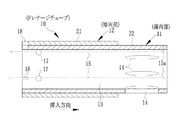
本発明のドレナージチューブ10は、図1ないし図3に示すように、軟性の合成樹脂で管状に作られており、内視鏡の鉗子管路を通じて体腔内に留置される。鉗子管路に挿入する方向(以下、挿入方向)の先端から順に、薄肉部(弾性変形部)11、厚肉部12で構成されており、内部には、体液を排出するための管路13が設けられている。
As shown in FIGS. 1 to 3, the
薄肉部11には、体液を排出するために、楕円状の開口14が周方向に所定ピッチで設けられている。薄肉部11の先端内周には、ワイヤ15の先端15aが固定されている。ワイヤ15は、管路13の内周のうちの周方向の3分割位置にそれぞれ配されており、鉗子管路を通って内視鏡の鉗子入口の外に呈する長さをそれぞれ有している。後端15bには、操作つまみ16がそれぞれ取り付けられている。ワイヤ15としては、柔らかい可撓性の糸、又はプラスチック材料で作られる線部材等を用いるのが、留置後に切断が容易なので望ましい。
In the
ドレナージチューブ10は、外層21と内層22との2層で構成された断面になっている。内層22は、薄肉部11までの長さになっており、外層21は厚肉部12のみの長さになっている。したがって、薄肉部11は、厚肉部12に比べてさらに軟性になっている。なお、ドレナージチューブ10の層構成としては、1層で作り、先端を薄肉に形成又は切削して薄肉部を作っても良い。
The
操作つまみ16は、挿入方向とは逆の方向に引く引っ張り位置と、挿入方向に押して緩める弛緩位置との間で押し引きされる。ワイヤ15は、操作つまみ16が引っ張り位置に引かれると先端15aで薄肉部11を座屈させて径方向に膨張させて抜け止め部20を生成する。抜け止め部20を生成した状態に保つために、各ワイヤ15には途中に玉部17が取り付けられており、また、玉部17が引っ掛けられる切り欠き部18が厚肉部12の後端に形成されている。なお、玉部17は、球状としているが、楕円状や矩形等、ワイヤ15よりも突出して引っ掛かる凸形状であればいずれの形状でもよい。
The
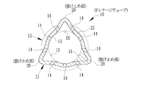
抜け止め部20は、図4ないし図6に示すように、操作つまみ16を引っ張り位置に引くことで、先端15aが固定されている薄肉部11の先端と薄肉部11の後端(厚肉部12との境界の部位)との間で座屈現象を生じさせ、座屈現象によりこれらの間が隆起して生成される。本実施形態では、ワイヤ15を周方向の3分割位置にそれぞれ設けているので、薄肉部11の周方向の3分割位置に抜け止め部20がそれぞれ生成される。ワイヤ15は、玉部17を切り欠き部18に引っ掛けた後に、玉部17の後方で切断される。玉部17を切り欠き部18から外すと、内層22自身の弾性によりワイヤ15が弛緩位置に戻り、薄肉部11の周面が略真っ直ぐに戻って、抜け止め部20が消滅する。なお、ワイヤ15の引き量としては、抜け止め部20のうちの厚肉部12との境界から頂点に向かって隆起する辺に、管路13に対して略垂直な起立部20aが作られる長さが望ましい。また、抜け止め部20を形成したときに、薄肉部11の先端周縁が輪を形成するように前記周縁部のみを厚くしておいてもよい。
As shown in FIG. 4 to FIG. 6, the
ドレナージチューブ10は、図7に示すように、内視鏡用ドレナージチューブ留置具30を用いて体腔内に留置される。内視鏡用ドレナージチューブ留置具30は、内視鏡の鉗子管路に挿入される挿入部31を持っている。この挿入部31は、可撓性のシース32と、その内部に挿通されているガイドワイヤ33で構成されている。ガイドワイヤ33の先端には、生体組織に穿刺される穿刺部34が設けられている。ガイドワイヤ33は、穿刺部34で体腔壁から膵管や胆管等を穿刺するとともに、穿刺により形成された孔にドレナージチューブ10を挿入するときのガイドの作用をする。ガイドワイヤ33の後端は、内視鏡の鉗子入口の外に呈されている。
As shown in FIG. 7, the
ドレナージチューブ10は、シース32の内部先端に配置され、かつ、ガイドワイヤ33に被嵌されている。なお、図7では図面の煩雑化を防ぐために、シース32とドレナージチューブ10との間に隙間が記載されているが、実際にはシース32に対してドレナージチューブ10の外面が軽く当接した状態にセットされており、よって、ドレナージチューブ10は摩擦係合によりシース32の内部の所定位置に動かないようにセットされている。
The
ガイドワイヤ33には、ドレナージチューブ10の背後に、プッシャー35がガイドワイヤ33の全長に渡って緩く被嵌されている。プッシャー35は、可撓性チューブによって形成されて、ガイドワイヤ33に対して進退自在に被嵌され、その先端面がドレナージチューブ10の後端面に当接している。内視鏡の鉗子入口の外の手元側での操作によりガイドワイヤ33に沿ってプッシャー35を前方に押せば、ドレナージチューブ10をガイドワイヤ33の先端から押し出すことができる。なお、ワイヤ15は、内視鏡の鉗子管路から露呈される手元操作側まではシース32とプッシャー35との間を通っており、手元操作側ではシース32に設けた開口から外に露呈されている。
A
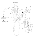
内視鏡用ドレナージチューブ留置具30の手元側には、図8に示すように、プッシャー35を押し出すためのプランジャー37、及びガイドワイヤ33を押し引きする操作するためのスライダ38を設けた操作部が設けられている。また、ドレナージチューブ10のワイヤ15の後端15bは、シース32の開口から内視鏡40の鉗子入口41の外に露呈されており、ワイヤ15の後端15bには、指掛け用の操作つまみ16が取り付けられている。操作つまみ16は、鉗子入口41に入り込まないようにするためのストッパの作用もなす。
As shown in FIG. 8, an operation in which a
内視鏡用ドレナージチューブ留置具30を使ってドレナージチューブ10を留置する。この場合、治療する目的、留置する部位により異なるが、ここでは膵仮性嚢胞の治療のためにドレナージチューブ10を留置する方法について説明する。まず十二指腸用内視鏡40の挿入部42を口から胃まで挿入する。内視鏡40は、挿入部42の内部空間に鉗子管路が挿通されており、鉗子管路の一端が内視鏡40の挿入部42の先端側部に開口して設けた鉗子出口43に、また、他端が手元操作部44に開口して設けた鉗子入口41にそれぞれ繋がっている。
The
また、周知のように、内視鏡40には、鉗子出口43の近傍に、観察窓、及び照明窓等が設けられている。内視鏡40は、映像処理回路を内蔵するプロセッサ45に接続され、プロセッサ45はモニタ46に接続されている。観察窓の奧に設けたCCD等の撮像センサで撮像した映像をモニタ46で見ることで、内視鏡40の挿入部42の挿入位置を確認でき、また、内視鏡用ドレナージチューブ留置具30の挿入部31の挿入量も確認することができる。また、鉗子出口43には、鉗子起立台が設けられている。内視鏡40の手元操作部44に設けた起立台用ノブ47を操作して起立台の起立角度を変更することで、内視鏡用ドレナージチューブ留置具30の挿入部31の先端部の挿入方向を変えることができる。
As is well known, the endoscope 40 is provided with an observation window, an illumination window, and the like in the vicinity of the
ドレナージチューブ10をセットした内視鏡用ドレナージチューブ留置具30の挿入部31を内視鏡40の鉗子入口41に挿入し、鉗子管路を通って鉗子出口43から導出させて、スライダ38を押し込む操作を行うことで、穿刺部34で留置する部位、例えば胃壁50と嚢胞51を穿刺する。穿刺後は、ガイドワイヤ33の先端を患部内に残したままの状態で、プランジャー37を押す操作を行うことで、ガイドワイヤ33をガイドにして孔にドレナージチューブ10を押し出す。これにより、ドレナージチューブ10は、ガイドワイヤ33に沿って送り出され、胃壁50と嚢胞51に開けた孔にセットされる。
The
ドレナージチューブ10を穿刺した孔にセットした後には、抜け止め部20を生成する操作を行う。この操作は、内視鏡40の鉗子入口41の外の手元側に露呈している操作つまみ16を引っ張り位置に向けて引く。これにより、ワイヤ15は、先端15aで薄肉部11を座屈させて薄肉部11の外周に抜け止め部20を生成する。ワイヤ15を所定量引いた後に緩めると、玉部17が切り欠き部18に引っ掛かる。これにより、抜け止め部20の生成を維持することができる。このとき、ドレナージチューブ10の背後に、プッシャー35が当接した状態で配されている、プッシャー35の前端には、図7に示すように、ガイド部52が設けられている。ガイド部52は、前方にある切り欠き部18に向けて玉部17を押し込むようにガイドする斜面をもっている。したがって、ワイヤ15が引かれると、ワイヤ15がプッシャー35の外周を通っているため、玉部17がガイド部52に乗り上がり、ワイヤ15が緩められることで玉部17が切り欠き部18にガイドされる。玉部17は、切り欠き部18に引っ掛かり、それ以上のワイヤ15の緩みを阻止する。これにより、抜け止め部20を生成した状態を維持することができる。
After the
抜け止め部20を生成した後には、プランジャー37、スライダ38を順に、引き操作してプッシャー35とガイドワイヤ33をシース32の内部に戻し、この状態で内視鏡用ドレナージチューブ留置具30を内視鏡40の鉗子管路から抜く。次に、内視鏡40の鉗子管路にナイフや挟み等の処置具を挿入して各ワイヤ15を玉部17の背後又は後方で切断する。そして、切断側のワイヤ15を鉗子管路から引き抜き、最後にナイフや挟み等の処置具を鉗子管路から抜くことで処置が終了する。
After the retaining
ドレナージチューブ10を交換又は抜去するときには、内視鏡40の挿入部42を口から胃まで挿入する。そして、手元操作により開閉自在な一対の挟持爪をもつ鉗子等の処置具を鉗子管路に挿入し、その処置具の一対の挟持爪で玉部17を挟んで切り欠き部18から外す。これにより、ドレナージチューブ10の薄肉部11は、自身の弾性により元の径に戻り、よって抜け止め部20が無くなる。その後は前記処置具の一対の挟持爪でドレナージチューブ10の一部を挟んでそのまま鉗子管路を通じて取り出す。このとき、ドレナージチューブ10には抜け止め部20が無いので、スムーズかつ組織への損傷なく取り外せ、生体に与える負担を軽減することができる。
When exchanging or removing the
上記実施形態では、ワイヤ15を3本用いて抜け止め部20を3個生成するようにしているが、本発明ではこの数に限らず、ワイヤ15を2本設けて相対する位置に抜け止め部20を2個作るようにしてもよいし、ワイヤ15を4本以上設けて周方向の等分割位置に抜け止め部20を生成するようにしてもよい。
In the above-described embodiment, three retaining
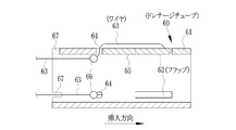
上記実施形態では、手元側の操作つまみを引くことでドレナージチューブ10の先端を座屈させて抜け止め部20を生成しているが、本発明ではこれに限らず、例えば図9及び図10に示すドレナージチューブ60のように、環状のチューブ61の一部を切り欠いたフラップ62をワイヤ63で起立位置に弾性変形させるように構成にしてもよい。
In the above embodiment, by pulling the operation knob on the hand side, the tip of the
この実施形態では、チューブ61の全体が弾性変形部を構成しており、フラップ62が、通常は自身の弾性により倒伏位置の状態となっている。ワイヤ63は、一端がフラップ62の外周先端側に固定され、フラップ62の後方に設けた開口64を通してドレナージチューブ10の内部の管路65に通されている。ワイヤ63には、玉部66がそれぞれ設けられている。玉部66は、フラップ62が倒伏位置のときに管路65内に位置し、起立位置のときにチューブ61の後端に設けた切り欠き部67に引っ掛かる位置にそれぞれ取り付けられている。
In this embodiment, the
留置するときには、前述した内視鏡用ドレナージチューブ留置具30にドレナージチューブ60をセットして内視鏡40の鉗子通路を通じて内視鏡用ドレナージチューブ留置具30の挿入部31を留置部位に導出させる。その後、スライダ38を押し操作して穿刺部34で体腔壁から膵管や胆管等を穿刺する。
When indwelling, the
穿刺後は、ガイドワイヤ33の先端を患部内に残したままの状態で、プランジャー37をセットしてガイドワイヤ33をガイドにして穿刺により形成された孔にドレナージチューブ60を差し込む。その後に、操作つまみ16を引くと、ワイヤ63が引かれてフラップ62が起立位置になる。このとき、玉部66がチューブ61の後端から僅かに突出する位置まで移動する。ドレナージチューブ60の背後には、プッシャー35が配されており、各ワイヤ63がプッシャーの外周に通されているから、スライダ38を引きワイヤ63を引くと、玉部66がドレナージチューブ60の管路65からプッシャー35の外周に向けて引かれてガイド部52に乗り上がる。その後、ワイヤ63を緩めることで玉部66がドレナージチューブ60の切り欠き部67に引っ掛かり、フラップ62が起立位置の姿勢を保つ。フラップ62を起立位置にすると、引き起こした後に開口62aが生成される。このとき、フラップ62は、管路65に対して略垂直な位置まで起立する。このため、係留がより確実になり、しかも開口62aも生成されるので体液の排出を効率良く行える。
After the puncture, with the tip of the guide wire 33 left in the affected area, the
フラップ62を起立位置に維持した後には、前述したように、プランジャー37、スライダ38を順に引き操作してプッシャー35とガイドワイヤ33をシース32の内部に戻し、この状態で内視鏡用ドレナージチューブ留置具30を内視鏡40の鉗子管路から抜く。次に、内視鏡40の鉗子管路にナイフや挟み等の処置具を挿入して各ワイヤ63を玉部66の背後又は後方で切断する。そして、切断側のワイヤ63を鉗子管路から引き抜き、最後にナイフや挟み等の処置具を鉗子管路から抜くことで処置が終了する。
After maintaining the
ドレナージチューブ60を交換又は抜去するときには、内視鏡40の挿入部42を口から胃まで挿入する。そして、手元操作により開閉自在な一対の挟持爪をもつ鉗子等の処置具を鉗子管路に挿入し、一対の挟持爪で玉部66を挟んで切り欠き部67から外す。これにより、フラップ62は、チューブ自身の弾性により元の径に戻り、よってフラップ62が開口62aを塞ぐ倒伏位置に戻る。その後はその一対の挟持爪でドレナージチューブ60の一部を挟んでそのまま鉗子管路を通じて取り出す。このとき、ドレナージチューブ60にはフラップ62が突出していないので、穿刺した孔からスムーズにかつ損傷なく取り外せ、生体に与える負担を軽減することができる。
When the
なお、フラップ62としては、周方向の3分割位置に3個設けているが、例えば相対する位置に2個、又は周方向の分割位置に4個以上設けても良い。
Note that three
上記実施形態では、ドレナージチューブ10,60を十二指腸用内視鏡で使用しているが、本発明ではこれに限らず、超音波内視鏡や腹腔鏡等でも使用することができるのは言うまでもない。この場合、例えば造形剤入りの合成樹脂でドレナージチューブ10,60を作るのが好適である。また、胆管に限らず、尿管や脳室等の他の臓器にも利用することができる。
In the above-described embodiment, the
10,60 ドレナージチューブ
11 薄肉部
12 厚肉部
13 管路
14 開口部
15 ワイヤ
16 操作つまみ
18 切り欠き部
21 外層
22 内層
40 内視鏡
41 鉗子入口
DESCRIPTION OF
Claims (6)
前記弾性変形部の一部と留置後に切り離される手元操作部とを繋ぐとともに、前記手元操作部の操作に連係して前記弾性変形部又はその一部に係留用の抜け止め部を生成する連結手段と、
前記抜け止め部が生成されたときに前記連結手段が元の位置に戻らないように阻止する阻止手段と、
を備えたことを特徴とするドレナージチューブ。 A flexible tube having an elastically deformed portion at the end;
A connecting means for connecting a part of the elastically deforming part and a hand operating part to be separated after placement, and generating a retaining part for anchoring in the elastically deforming part or a part thereof in conjunction with the operation of the hand operating part When,
Blocking means for preventing the connecting means from returning to the original position when the retaining portion is generated;
A drainage tube characterized by comprising:
前記阻止手段は、ワイヤの途中に設けた凸部と、前記手元操作部の操作より前記抜け止め部が生成される長さだけ前記ワイヤが引かれたときに前記凸部が引っ掛けられる切り欠き部と、で構成されていることを特徴とする請求項1記載のドレナージチューブ。 The connecting means is a wire,
The blocking means includes a convex portion provided in the middle of the wire and a notch portion on which the convex portion is hooked when the wire is pulled by a length that generates the retaining portion by the operation of the hand operating portion. The drainage tube according to claim 1, comprising:
前記連結手段は、前記弾性変形部の先端内周と前記手元操作部とを繋いでおり、前記手元操作部の操作に連係して前記弾性変形部の先端と後端との間を座屈させることにより抜け止め部を生成することを特徴とする請求項1又は2記載のドレナージチューブ。 The elastic deformation part is made softer than other parts,
The connecting means connects the inner periphery of the distal end of the elastic deformation portion and the hand operation portion, and buckles between the front end and the rear end of the elastic deformation portion in conjunction with the operation of the hand operation portion. The drainage tube according to claim 1, wherein a retaining portion is generated.
Priority Applications (1)
| Application Number | Priority Date | Filing Date | Title |
|---|---|---|---|
| JP2008297539A JP2010119737A (en) | 2008-11-21 | 2008-11-21 | Drainage tube |
Applications Claiming Priority (1)
| Application Number | Priority Date | Filing Date | Title |
|---|---|---|---|
| JP2008297539A JP2010119737A (en) | 2008-11-21 | 2008-11-21 | Drainage tube |
Publications (1)
| Publication Number | Publication Date |
|---|---|
| JP2010119737A true JP2010119737A (en) | 2010-06-03 |
Family
ID=42321600
Family Applications (1)
| Application Number | Title | Priority Date | Filing Date |
|---|---|---|---|
| JP2008297539A Pending JP2010119737A (en) | 2008-11-21 | 2008-11-21 | Drainage tube |
Country Status (1)
| Country | Link |
|---|---|
| JP (1) | JP2010119737A (en) |
Cited By (11)
| Publication number | Priority date | Publication date | Assignee | Title |
|---|---|---|---|---|
| JP2017064295A (en) * | 2015-10-02 | 2017-04-06 | 日本ゼオン株式会社 | Catheter and stent delivery device |
| CN107670165A (en) * | 2017-09-28 | 2018-02-09 | 杭州市第人民医院 | Stop that surrounding tissue grows the double-jacket tube to tubular body |
| JP2018033867A (en) * | 2016-09-02 | 2018-03-08 | テルモ株式会社 | Medical tube |
| JP2019500133A (en) * | 2015-12-30 | 2019-01-10 | ヌハート エーエスNuheart As | Transcatheter insertion system |
| JPWO2018061598A1 (en) * | 2016-09-30 | 2019-07-11 | 株式会社タケモリ | catheter |
| CN111388844A (en) * | 2020-03-26 | 2020-07-10 | 杭州市第一人民医院 | Medical pulse double cannula |
| KR20220056327A (en) * | 2020-10-28 | 2022-05-06 | 김응석 | Catheter for chest using a string |
| US11752300B2 (en) | 2015-07-20 | 2023-09-12 | Roivios Limited | Catheter device and method for inducing negative pressure in a patient's bladder |
| US11896785B2 (en) | 2015-07-20 | 2024-02-13 | Roivios Limited | Ureteral and bladder catheters and methods of inducing negative pressure to increase renal perfusion |
| US11904121B2 (en) | 2015-07-20 | 2024-02-20 | Roivios Limited | Negative pressure therapy system |
| US11918754B2 (en) | 2015-07-20 | 2024-03-05 | Roivios Limited | Ureteral and bladder catheters and methods of inducing negative pressure to increase renal perfusion |
-
2008
- 2008-11-21 JP JP2008297539A patent/JP2010119737A/en active Pending
Cited By (14)
| Publication number | Priority date | Publication date | Assignee | Title |
|---|---|---|---|---|
| US11752300B2 (en) | 2015-07-20 | 2023-09-12 | Roivios Limited | Catheter device and method for inducing negative pressure in a patient's bladder |
| US11918754B2 (en) | 2015-07-20 | 2024-03-05 | Roivios Limited | Ureteral and bladder catheters and methods of inducing negative pressure to increase renal perfusion |
| US11904113B2 (en) | 2015-07-20 | 2024-02-20 | Roivios Limited | Ureteral and bladder catheters and methods of inducing negative pressure to increase renal perfusion |
| US11904121B2 (en) | 2015-07-20 | 2024-02-20 | Roivios Limited | Negative pressure therapy system |
| US11896785B2 (en) | 2015-07-20 | 2024-02-13 | Roivios Limited | Ureteral and bladder catheters and methods of inducing negative pressure to increase renal perfusion |
| JP2017064295A (en) * | 2015-10-02 | 2017-04-06 | 日本ゼオン株式会社 | Catheter and stent delivery device |
| JP2019500133A (en) * | 2015-12-30 | 2019-01-10 | ヌハート エーエスNuheart As | Transcatheter insertion system |
| JP2018033867A (en) * | 2016-09-02 | 2018-03-08 | テルモ株式会社 | Medical tube |
| JP7115686B2 (en) | 2016-09-30 | 2022-08-09 | 株式会社タケモリ | catheter |
| JPWO2018061598A1 (en) * | 2016-09-30 | 2019-07-11 | 株式会社タケモリ | catheter |
| CN107670165A (en) * | 2017-09-28 | 2018-02-09 | 杭州市第人民医院 | Stop that surrounding tissue grows the double-jacket tube to tubular body |
| CN111388844A (en) * | 2020-03-26 | 2020-07-10 | 杭州市第一人民医院 | Medical pulse double cannula |
| KR102486930B1 (en) * | 2020-10-28 | 2023-01-09 | 김응석 | Catheter for chest using a string |
| KR20220056327A (en) * | 2020-10-28 | 2022-05-06 | 김응석 | Catheter for chest using a string |
Similar Documents
| Publication | Publication Date | Title |
|---|---|---|
| JP2010119737A (en) | Drainage tube | |
| JP5764577B2 (en) | Endoscope sheath | |
| JP5166133B2 (en) | Endoscope | |
| US7959559B2 (en) | Endoscope insertion assisting device, endoscope apparatus, medical treatment device and endoscope insertion method | |
| US8343036B1 (en) | Flaccid tubular membrane and insertion appliance for surgical intubation | |
| JP5383980B2 (en) | Intubation system for use with an endoscope | |
| EP1769717A1 (en) | Endoscope insert part, endoscope, and endoscope system | |
| CN107874798B (en) | Lead puncture needle | |
| JP5064077B2 (en) | Medical snare device | |
| JP2009082536A (en) | Ligature appliance for endoscope and endoscope ligature system | |
| JP2007296323A (en) | Intubation instrument for enteral feeding | |
| JP4524393B2 (en) | Rapalloport | |
| KR102536177B1 (en) | Stone extraction mesh basket and double cavity end cap used for stone extraction mesh basket | |
| JP2008253774A (en) | Endoscope apparatus | |
| JP2006288615A (en) | Treating instrument unit | |
| JP5752740B2 (en) | Endoscopic sliding tube | |
| JP3772085B2 (en) | Endoscope device | |
| US8460248B2 (en) | Endoscopic bite guard and related methods of use | |
| CN105708406A (en) | Visible ureter soft endoscopic sheath | |
| JPWO2003092782A1 (en) | Indwelling tube guide device | |
| JP5927365B1 (en) | Medical treatment tool | |
| JP2006521895A (en) | Guide wire structure for insertion into the interior space | |
| CA2717756C (en) | Medical systems for accessing an internal bodily opening | |
| US9974556B2 (en) | Method for inserting endoscopic device into hollow organ using guide wire | |
| JP5414727B2 (en) | Drainage tube insertion tool |