JP2010117841A - Image detection device, recognition method of input position and program - Google Patents
Image detection device, recognition method of input position and program Download PDFInfo
- Publication number
- JP2010117841A JP2010117841A JP2008289925A JP2008289925A JP2010117841A JP 2010117841 A JP2010117841 A JP 2010117841A JP 2008289925 A JP2008289925 A JP 2008289925A JP 2008289925 A JP2008289925 A JP 2008289925A JP 2010117841 A JP2010117841 A JP 2010117841A
- Authority
- JP
- Japan
- Prior art keywords
- sensor
- input
- planar member
- data
- image
- Prior art date
- Legal status (The legal status is an assumption and is not a legal conclusion. Google has not performed a legal analysis and makes no representation as to the accuracy of the status listed.)
- Pending
Links
Images


Landscapes
- Position Input By Displaying (AREA)
Abstract
【課題】情報機器とユーザとの間の対話を円滑化する。
【解決手段】本発明に係る像検知装置は、面状部材(センサ内蔵液晶パネル301など)が検知した対象物(指64など)の像に基づいて、面状部材上の選択された領域(選択領域360)の位置を検出し、当該対象物の像から対象物の進入方向を検出し、当該進入方向に応じて上記領域の位置に対する補正の方向を決定して当該領域の位置に対する補正を行い、当該補正後の位置を面状部材に対する入力位置として認識する。
【選択図】図2To facilitate a dialogue between an information device and a user.
An image detection apparatus according to the present invention is configured to select a selected region on a planar member (such as a finger 64) based on an image of an object (such as a finger 64) detected by the planar member (such as a liquid crystal panel with a built-in sensor 301). The position of the selected area 360) is detected, the approach direction of the object is detected from the image of the object, the correction direction for the position of the area is determined according to the approach direction, and the correction for the position of the area is performed. Then, the corrected position is recognized as an input position for the planar member.
[Selection] Figure 2
Description
本発明は、像検知装置、及び該装置における入力位置の認識方法に関するものである。また、当該像検知装置を動作させるためのプログラムに関する。 The present invention relates to an image detection apparatus and an input position recognition method in the apparatus. The present invention also relates to a program for operating the image detection apparatus.
情報化社会の発展に伴い、様々な場面において情報機器が利用される。そのため、情報機器とそのユーザとの対話を円滑化する技術は非常に重要である。とりわけ、情報機器に対する、ユーザによる情報入力を円滑化する技術の開発がもとめられている。例えば、特許文献1には、情報機器に表示された反応領域(アイコンなど)をユーザが上手く選択できなかった場合に、当該反応領域を拡大表示してユーザを補助する技術が開示されている。
With the development of the information society, information equipment is used in various situations. Therefore, a technique for facilitating a dialogue between an information device and its user is very important. In particular, the development of a technology for facilitating information input by a user for information equipment is being sought. For example,
また、近年、低コストでかつデザイン性に優れるという観点から、入力端末としてタッチパネル式の入力キーを備えた情報機器が増加している。しかし、例えばタッチパネル式の入力キーでは、当該入力キーの中心をユーザが正確に触れることは少なく、通常のキーボード入力と比較して誤入力の問題が生じ易い。 In recent years, information devices having touch panel type input keys as input terminals are increasing from the viewpoint of low cost and excellent design. However, for example, with a touch panel type input key, the user rarely touches the center of the input key accurately, and a problem of erroneous input is likely to occur compared to normal keyboard input.
そこで、特許文献2に記載のように、ユーザのタッチ位置から離れた位置に、当該タッチ位置と重複しないようにポインタを表示してユーザを補助するタッチパネル式入力端末を備えた情報機器が提案されている。
しかしながら、特許文献1及び2に記載の技術では、ユーザによる情報入力は十分には円滑とはならず、さらなる改良がもとめられている。
However, in the techniques described in
とりわけ、情報機器の小型化に伴い、入力キー自身もより小さくなり、かつ片手で操作を行うユーザが増加したため、誤入力の問題がより生じ易くなっている現状がある。 In particular, with the downsizing of information equipment, the number of input keys themselves has become smaller and the number of users who operate with one hand has increased.
本発明は、上記課題に鑑みてなされたものであり、特に情報機器に対するユーザの入力を円滑化する技術を提供することを主たる目的とする。 The present invention has been made in view of the above problems, and it is a main object of the present invention to provide a technique for facilitating user input to an information device.
本発明に係る像検知装置は、上記の課題を解決するために、像を検知する面状部材と、面状部材が検知した対象物の像に基づいて、選択された当該面状部材上の領域の位置を検出する選択位置検出手段と、面状部材が検知した対象物の像から対象物の進入方向を検出する進入方向検出手段と、上記領域の位置に対する補正を行い、当該補正後の位置を面状部材に対する入力位置として認識する入力位置認識手段とを備え、入力位置認識手段は、進入方向検出手段が検出した上記進入方向に応じて上記補正の方向を決定する、ことを特徴としている。 In order to solve the above problems, an image detection device according to the present invention is based on a planar member that detects an image and an image of an object detected by the planar member. A selection position detection means for detecting the position of the area, an approach direction detection means for detecting the approach direction of the object from the image of the object detected by the planar member, and a correction for the position of the area. Input position recognizing means for recognizing the position as an input position for the planar member, and the input position recognizing means determines the correction direction according to the approach direction detected by the approach direction detecting means. Yes.
上記の構成によれば、対象物による現実の選択位置に対して、当該対象物の進入方向を考慮した方向に位置補正を行い、当該補正後の位置を面状部材に対する入力位置として認識する。これにより、対象物の進入方向に応じたより正確な入力操作を実現することができる。 According to said structure, position correction is performed in the direction which considered the approach direction of the said target object with respect to the actual selection position by a target object, and the position after the said correction | amendment is recognized as an input position with respect to a planar member. Thereby, more accurate input operation according to the approach direction of a target object is realizable.
本発明に係る像検知装置では、進入方向検出手段は、面状部材の面内方向における対象物の進入方向を検出し、入力位置認識手段は、選択位置検出手段が検出した領域の位置を進入方向に沿う方向に補正する構成としてもよい。なお、本発明において「面状部材の面内方向における対象物の進入方向」とは、対象物の、面状部材に対する二次元的な進入方向を指す。 In the image detection apparatus according to the present invention, the approach direction detection means detects the approach direction of the object in the in-plane direction of the planar member, and the input position recognition means enters the position of the area detected by the selected position detection means. It is good also as a structure correct | amended in the direction along a direction. In the present invention, the “entry direction of the object in the in-plane direction of the planar member” refers to a two-dimensional entry direction of the object with respect to the planar member.
上記の構成によれば、対象物による現実の選択位置に対して、対象物の進入方向に沿う方向に補正し、より正確な入力操作を実現することができる。 According to said structure, it correct | amends to the direction in alignment with the approach direction of a target object with respect to the actual selection position by a target object, and can implement | achieve more exact input operation.
特に限定されないが、例えば、上記面状部材が、当該面状部材上の各位置における受光量を検出するフォトダイオード群を備え、当該フォトダイオード群が検出した受光量の変化に基づいて上記近傍の像を検知する場合には、対象物が面状部材に接触する前に検知される場合もある。このような場合に、対象物による現実の選択位置に対して、対象物の進入方向に沿う方向(すなわち、対象物が進むであろう方向)に位置補正を行い、より正確な入力操作を実現することができる。 Although not particularly limited, for example, the planar member includes a photodiode group that detects the amount of light received at each position on the planar member, and based on a change in the amount of received light detected by the photodiode group, When an image is detected, it may be detected before the object contacts the planar member. In such a case, the position is corrected in the direction along the entry direction of the object (that is, the direction in which the object will travel) with respect to the actual selected position by the object, thereby realizing a more accurate input operation. can do.
本発明に係る像検知装置では、進入方向検出手段は、対象物の進入方向が、面状部材の面内における特定方向又は当該特定方向と反対方向の何れにより近い方向であるかを検出し、入力位置認識手段は、進入方向が特定方向により近い場合は、前記領域の位置を特定方向に沿って補正し、進入方向が特定方向と反対方向により近い場合は、前記領域の位置を当該反対方向に沿って補正する構成としてもよい。 In the image detection device according to the present invention, the approach direction detection means detects whether the approach direction of the object is closer to a specific direction in the surface of the planar member or a direction opposite to the specific direction, The input position recognition means corrects the position of the area along the specific direction when the approach direction is closer to the specific direction, and sets the position of the area in the opposite direction when the approach direction is closer to the opposite direction to the specific direction. It is good also as a structure correct | amended along.
なお、対象物の進入方向が、上記特定方向とそれに相対する反対方向との何れにより近いかの判定は、当該進入方向が何れの方向と鋭角に交わるかを基準に定めればよい。 The determination of whether the approach direction of the object is closer to the specific direction or the opposite direction relative to the specific direction may be determined based on which direction the approach direction intersects with an acute angle.
上記の構成によれば、対象物の進入方向を大きく二方向(特定方向/特定方向と反対方向)に分類して補正を行う。これにより、補正が簡潔となるとともに、より正確な入力操作を実現することができる。 According to said structure, it correct | amends by classifying the approach direction of a target object roughly into two directions (specific direction / direction opposite to a specific direction). As a result, the correction is simplified and a more accurate input operation can be realized.
なお、基準となる上記特定方向は、予め任意に定めておき、検知装置の記憶部に格納しておけばよい。また、特定方向としては、具体的には例えば、1)面状部材の面内に複数の入力キーが設けられている場合には、当該入力キーの並び方向の何れか、2)ユーザが像検知装置を使用する際に、当該ユーザにとって面状部材の左側端から右向き方向又はその逆方向(面状部材の面内におけるX軸の+方向又は−方向)、或いは、上側端から下向き方向又はその逆方向(面状部材の面内におけるY軸の−方向又は+方向)となる方向の何れか、などが好適なものとして挙げられる。 Note that the specific direction as a reference may be arbitrarily determined in advance and stored in the storage unit of the detection device. The specific direction is specifically, for example, 1) When a plurality of input keys are provided in the surface of the planar member, any one of the input key arrangement directions, and 2) a user image When using the detection device, for the user, the right direction from the left end of the planar member or the opposite direction (the X direction + direction or − direction in the plane of the planar member), or the downward direction from the upper end, or Any of the opposite directions (the direction of the Y-axis in the plane of the planar member, or the + direction) is preferable.
特に、ユーザが片手で持ち、残りの指で操作するタイプの像検知装置の場合、ユーザが左利きであれば面状部材の左側から、右利きであれば面状部材の右側から、操作する指が進入するのが通常である。よって、上記特定方向は、上記2)のうちユーザにとり面状部材の左側端から右向き方向、又はその逆方向の何れかであることが好ましい。 In particular, in the case of an image detection device of the type that the user holds with one hand and operates with the remaining fingers, the finger operated from the left side of the planar member if the user is left-handed, and from the right side of the planar member if the user is right-handed It is normal to enter. Therefore, it is preferable that the specific direction is either the rightward direction from the left end of the planar member or the opposite direction to the user in the above 2).
本発明に係る像検知装置では、進入方向検出手段は、予め定めた基準軸に対する対象物の進入角αを検出し、入力位置認識手段は、進入角αが45度以下の場合に前記補正を行う構成としてもよい。なお、進入角αは基準軸に対する角度のうち、90度以下の角度のことを指す。 In the image detection apparatus according to the present invention, the approach direction detection means detects the approach angle α of the object with respect to a predetermined reference axis, and the input position recognition means performs the correction when the approach angle α is 45 degrees or less. It is good also as a structure to perform. The approach angle α indicates an angle of 90 degrees or less among the angles with respect to the reference axis.
上記の構成によれば、誤入力が生じやすい、進入角αが45度以下の場合のみに補正を行う。これにより、必要な場合のみ補正がなされるとともに、より正確な入力操作を実現することができる。 According to said structure, it correct | amends only when the approach angle (alpha) is 45 degrees or less which an error input tends to produce. Thus, correction is performed only when necessary, and more accurate input operation can be realized.
なお、上記基準軸は、予め任意に定めておき像検知装置の記憶部に格納しておけばよい。また、基準軸としては、具体的には例えば、1)面状部材の面内に複数の入力キーが設けられている場合には、当該入力キーの並び方向の何れかの方向に延びる軸、2)ユーザが像検知装置を使用する際に、当該ユーザにとり面状部材の左右方向(面状部材の面内におけるX軸)、或いは、上下方向(面状部材の面内におけるY軸)となる方向の何れかに延びる軸、などが好適なものとして挙げられる。 The reference axis may be arbitrarily determined in advance and stored in the storage unit of the image detection apparatus. Further, as the reference axis, specifically, for example, 1) when a plurality of input keys are provided in the surface of the planar member, an axis extending in any one of the arrangement directions of the input keys; 2) When the user uses the image detection device, the horizontal direction of the planar member (X axis in the plane of the planar member) or the vertical direction (Y axis in the plane of the planar member) for the user An axis extending in any direction is preferable.
特に、ユーザが片手で持ち、残りの指で操作するタイプの像検知装置の場合には、上記基準軸は、上記2)に示す面状部材の左右方向に延びる軸(X軸)であることが好ましい。この場合、進入角αが90度により近いほど、操作する指は近傍の入力キーを選択しようとしていると考えられるので、誤入力が起こる確率が比較的低い。一方、進入角αが45度以下になれば、操作する指はより遠くの入力キーを選択しようとして負荷がかかっている状態と考えられるので、誤入力が起こる確率が比較的高い。 In particular, in the case of an image detection apparatus of the type that the user holds with one hand and operates with the remaining fingers, the reference axis is an axis (X axis) extending in the left-right direction of the planar member shown in 2) above. Is preferred. In this case, as the approach angle α is closer to 90 degrees, it is considered that the finger to be operated is trying to select a nearby input key, so that the probability of erroneous input is relatively low. On the other hand, if the approach angle α is 45 degrees or less, it is considered that the finger to be operated is under a load to try to select a distant input key, so that the probability of erroneous input is relatively high.
また、上記のように特定方向又はその反対方向に沿う方向を補正の方向とする場合には、上記基準軸を当該特定方向に延びる軸とすることがより好ましい。 Moreover, when the direction along the specific direction or the opposite direction is set as the correction direction as described above, it is more preferable that the reference axis is an axis extending in the specific direction.
本発明に係る像検知装置では、入力位置認識手段により認識された入力位置を示すポインタを面状部材に表示する構成としてもよい。 In the image detection apparatus according to the present invention, a pointer indicating the input position recognized by the input position recognition unit may be displayed on the planar member.
上記の構成によれば、入力位置と認識されている箇所がポインタで示されるため、ユーザの入力操作を補助することができる。 According to said structure, since the location recognized as an input position is shown with a pointer, a user's input operation can be assisted.
本発明に係る像検知装置では、面状部材に入力キーが設けられており、選択位置検出手段が検出した領域の位置が、入力キーの中心から外れている場合に、入力位置認識手段による補正を行う構成としてもよい。 In the image detection apparatus according to the present invention, the input key is provided on the planar member, and the correction by the input position recognition unit is performed when the position of the area detected by the selection position detection unit deviates from the center of the input key. It is good also as composition which performs.
上記の構成によれば、対象物による現実の選択位置が入力キーの中心から外れている場合のみ補正を行う。これにより、必要な場合のみ補正がなされるとともに、より正確な入力操作を実現することができる。 According to said structure, it correct | amends only when the actual selection position by a target object has remove | deviated from the center of the input key. Thus, correction is performed only when necessary, and more accurate input operation can be realized.
本発明に係る像検知装置では、面状部材に複数の入力キーが設けられており、隣接する入力キー間のキーピッチをAとした場合に、入力位置認識手段による補正は、その補正量がA×進入角α÷90の関係式を満たすように行われる構成としてもよい。 In the image detection apparatus according to the present invention, a plurality of input keys are provided on the planar member, and when the key pitch between adjacent input keys is A, the correction by the input position recognition means has a correction amount of A. * It is good also as a structure performed so that the relational expression of the approach angle (alpha) ÷ 90 may be satisfy | filled.
上記の構成によれば、進入角α及びキーピッチに応じて補正量を決定し、より正確な入力操作を実現することができる。 According to the above configuration, the correction amount is determined according to the approach angle α and the key pitch, and a more accurate input operation can be realized.
なお、上記キーピッチとは、隣接する入力キーの重心間距離である。 The key pitch is a distance between the centers of gravity of adjacent input keys.
本発明に係る像検知装置では、面状部材に複数の入力キーが設けられており、入力位置認識手段による補正は、隣接する入力キー間のキーピッチの半分以下の補正量で行われる構成としてもよい。 In the image detection apparatus according to the present invention, the planar member is provided with a plurality of input keys, and the correction by the input position recognition means may be performed with a correction amount equal to or less than half the key pitch between adjacent input keys. Good.
上記の構成によれば、キーピッチに応じて補正量の上限を決定し、より正確な入力操作を実現することができる。 According to said structure, the upper limit of the correction amount is determined according to a key pitch, and more accurate input operation can be implement | achieved.
本発明に係る入力位置の認識方法は、上記の課題を解決するために、像を検知する面状部材を含んでなる像検知装置における入力位置の認識方法であって、検知した対象物の像に基づいて、対象物により選択された面状部材上の領域の位置を検出する選択位置検出工程と、検知した対象物の像から面状部材に対する対象物の進入方向を検出する進入方向検出工程と、検出した進入方向に応じて上記領域の位置に対する補正の方向を決定して、当該領域の位置に対する補正を行い、補正後の位置を面状部材に対する入力位置として認識する入力位置認識工程と、を含むことを特徴としている。 In order to solve the above problems, an input position recognition method according to the present invention is an input position recognition method in an image detection apparatus including a planar member for detecting an image, and an image of a detected object. And a selection position detecting step for detecting the position of the area on the planar member selected by the target, and an approach direction detecting step for detecting the approach direction of the target with respect to the planar member from the detected image of the target And an input position recognition step of determining a correction direction for the position of the area according to the detected approach direction, performing correction for the position of the area, and recognizing the corrected position as an input position for the planar member; It is characterized by including.
上記の構成によれば、本発明に係る像検知装置と同様の作用効果を奏する。 According to said structure, there exists an effect similar to the image detection apparatus which concerns on this invention.
また、本発明に係る像検知装置を動作させるためのプログラムであって、コンピュータを上記の各手段として駆動させることを特徴とするプログラムおよび該プログラムを記録したコンピュータ読み取り可能な記録媒体も本発明の範疇に含まれる。 Further, a program for operating the image detection apparatus according to the present invention, which is characterized in that the computer is driven as each of the above-described means, and a computer-readable recording medium storing the program are also included in the present invention. Included in the category.
本発明によれば、像を検知する面状部材における、対象物による現実の選択位置に対して、当該対象物の進入方向を考慮した方向に位置補正を行い、当該補正後の位置を面状部材に対する入力位置として認識する。これにより、対象物の進入方向に応じたより正確な入力操作を実現することができる。 According to the present invention, in the planar member for detecting an image, position correction is performed in a direction in consideration of the approach direction of the object with respect to the actual selected position by the object, and the corrected position is planar. Recognized as an input position for the member. Thereby, more accurate input operation according to the approach direction of a target object is realizable.
(データ表示/センサ装置の動作の概要)
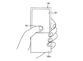
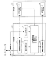
図1は、本発明の一実施形態に係るデータ表示/センサ装置100の外観を模式的に示す図である。図1に示すように、データ表示/センサ装置100は筐体の一面にセンサ内蔵液晶パネル(面状部材)301が配設されており、その長方形状のパネル面(表示面)にて画像の表示及び情報の入力を受付けるタッチパネル式の入力・表示装置である。データ表示/センサ装置100は、センサ内蔵液晶パネル301が配されないグリップ部100aを有し、ユーザが当該グリップ部100aを片手で握り持ちながら、片手の親指(対象物)64により情報の入力などの操作がなされる。
(Outline of data display / sensor device operation)
FIG. 1 is a diagram schematically showing an appearance of a data display /
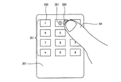
図2は、図1に記載のデータ表示/センサ装置100の動作の一例を模式的に示す図である。一例において、センサ内蔵液晶パネル301の表示面には、複数の入力キー350から構成されるスクリーンキーボード351が表示されている。
FIG. 2 is a diagram schematically illustrating an example of the operation of the data display /
そして、指64が上記表示面上の特定の領域(選択領域360)を選択したとき、センサ内蔵液晶パネル301に対する指64の進入方向に基づいて選択領域360の位置に対する補正が加えられ、当該補正後の位置が指64による入力位置として認識される。また、当該補正後の位置には、必要に応じてその位置を示す目印であるポインタ361が表示される。
Then, when the
具体的には、図2では、センサ内蔵液晶パネル301に対して右側から指64が進入しており、選択領域360から左側に所定の距離はなれた補正後の位置が、指64による入力位置として認識される。また、当該補正後の位置には、その位置を中心とした円形のポインタ361が表示される。なお、図2では、説明の便宜上、選択領域360と指64の先端とを互いにずれた状態で示しているが、実際には両者は重複している。
Specifically, in FIG. 2, the
本明細書において「選択領域」及び「選択位置」とは、順に、「指64により実際に選択された表示面上の領域」及び「指64により実際に選択された表示面上の領域の位置(領域全体又はその一部の位置を示すものでもよく、或いは領域に含まれる点の位置を示すものであってもよい)」を指し、指64の進入方向に基づいて補正された後の位置を表す「入力位置」とは区別される。
In this specification, “selection area” and “selection position” refer to “area on the display surface actually selected by the
一般にスクリーンキーボードに対する入力では、ユーザの指が入力キーの中心を正確に触れることは少ない。また、光センサを用いて入力の有無を検知する方式では、ユーザの指がスクリーンキーボードに所定距離まで近接した状態をもって入力有りと検知する場合がある。そのため、入力キーを押し込むタイプの通常のキーボード入力と比較して誤入力の問題が生じ易い。しかしながら、本発明に係るデータ表示/センサ装置100では、指64により選択された選択領域360に対して、指64の進入方向に応じた位置補正を行い、補正後の位置を指64による入力位置として認識する。そのため、誤入力の発生が低減する。
In general, when inputting to a screen keyboard, the user's finger rarely touches the center of the input key accurately. Further, in the method of detecting the presence or absence of input using an optical sensor, it may be detected that there is an input when the user's finger is close to a screen keyboard up to a predetermined distance. Therefore, a problem of erroneous input is likely to occur as compared with a normal keyboard input type in which an input key is pressed. However, in the data display /
さらに、上記補正後の位置に対応してポインタ361が表示されるので、ユーザは入力位置として認識されている領域を容易に知ることができ、スクリーンキーボード351を介した入力を円滑に行なうことができる。
Furthermore, since the
なお、入力の実行は、センサ内蔵液晶パネル301の表示面に指64が接触又は近接したと同時に行われてもよく、或いは、指64を当該表示面に一旦接触又は近接させた後、離す動作(アップ動作)がなされる際に行われてもよい。アップ動作時に入力が実行される構成では、ポインタ361の位置を指標にしたより正確な入力が実現可能である。
The input may be performed simultaneously with the
なお、ユーザは、指64の他にも、タッチペンなどの遮光物を用いてセンサ内蔵液晶パネル301上を指示してもよい。
In addition to the
以下、上述した機能を実現する各部材の構成について詳細に説明する。まず、上記データ表示/センサ装置100が備えるセンサ内蔵液晶パネル301の概要について説明する。
Hereinafter, the structure of each member which implement | achieves the function mentioned above is demonstrated in detail. First, an outline of the sensor built-in
(センサ内蔵液晶パネルの概要)
上記データ表示/センサ装置100が備えるセンサ内蔵液晶パネル301は、データの表示に加え、対象物の画像検出が可能な液晶パネルである。ここで、対象物の画像検出とは、例えば、ユーザが指やペンなどでポインティング(タッチ)した位置(選択位置)の検出や、印刷物などの画像の読み取り(スキャン)である。なお、表示に用いるデバイスは、液晶パネルに限定されるものではなく、有機EL(Electro Luminescence)パネルなどであってもよい。
(Outline of LCD panel with built-in sensor)
The sensor built-in
図3を参照しながら、センサ内蔵液晶パネル301の構造について説明する。図3は、センサ内蔵液晶パネル301の断面を模式的に示す図である。なお、ここで説明するセンサ内蔵液晶パネル301は一例であり、表示面と読取面とが共用されているものであれば、任意の構造のものが利用できる。
The structure of the sensor built-in
図示のとおり、センサ内蔵液晶パネル301は、背面側に配置されるアクティブマトリクス基板51Aと、表面側に配置される対向基板51Bとを備え、これら基板の間に液晶層52を挟持した構造を有している。アクティブマトリクス基板51Aには、画素電極56、データ信号線57、光センサ回路32(図示せず)、配向膜58、偏光板59などが設けられる。対向基板51Bには、カラーフィルタ53r(赤)、53g(緑)、53b(青)、遮光膜54、対向電極55、配向膜58、偏光板59などが設けられる。また、センサ内蔵液晶パネル301の背面には、バックライト307が設けられている。
As shown in the figure, the sensor built-in
なお、光センサ回路32に含まれるフォトダイオード6は、青のカラーフィルタ53bを設けた画素電極56の近傍に設けられているが、この構成に限定されるものではない。赤のカラーフィルタ53rを設けた画素電極56の近傍に設けてもよいし、緑のカラーフィルタ53gを設けた画素電極56の近傍に設けてもよい。
The
次に、図4(a)および図4(b)を参照しながら、ユーザが、指やペンで、センサ内蔵液晶パネル301上をタッチした位置(選択位置)を検出する2種類の方法について説明する。
Next, with reference to FIG. 4A and FIG. 4B, two types of methods for detecting a position (selected position) where the user touches the sensor built-in
図4(a)は、反射像を検知することにより、ユーザがタッチした位置を検出する様子を示す模式図である。バックライト307から光63が出射されると、フォトダイオード6を含む光センサ回路32は、指64などの対象物により反射された光63を検知する。これにより、当該対象物の反射像を検知することができる。このように、センサ内蔵液晶パネル301は、反射像を検知することにより、タッチした位置を検出することができる。
FIG. 4A is a schematic diagram showing how the position touched by the user is detected by detecting the reflected image. When the light 63 is emitted from the
また、図4(b)は、影像を検知することにより、ユーザがタッチした位置を検出する様子を示す模式図である。図4(b)に示すように、フォトダイオード6を含む光センサ回路32は、対向基板51Bなどを透過した外光61を検知する。しかしながら、ペンなどの対象物62がある場合は、外光61の入射が妨げられるので、光センサ回路32が検知する光量が減る。これにより、対象物62の影像を検知することができる。このように、センサ内蔵液晶パネル301は、影像を検知することにより、タッチした位置を検出することもできる。
FIG. 4B is a schematic diagram showing a state in which a position touched by the user is detected by detecting a shadow image. As shown in FIG. 4B, the
上述のように、フォトダイオード6は、バックライト307より出射された光の反射光(影像)を検知してもよいし、外光による影像を検知してもよい。また、上記2種類の検知方法を併用して、影像と反射像とを両方を同時に検知するようにしてもよい。
As described above, the
(データ表示/センサ装置の要部構成)
次に、図5を参照しながら、上記データ表示/センサ装置100の要部構成について説明する。図5は、データ表示/センサ装置100の要部構成を示すブロック図である。図示のように、データ表示/センサ装置100は、1または複数の表示/光センサ部300、回路制御部600、データ処理部700、主制御部800、記憶部901、一次記憶部902、操作部903、外部通信部907、音声出力部908、および音声入力部909を備えている。ここでは、データ表示/センサ装置100は、単一の表示/光センサ部300を備えているものとして説明するが、複数備えていてもかまわない。
(Data display / sensor configuration)
Next, the configuration of the main part of the data display /
表示/光センサ部300は、いわゆる光センサ内蔵液晶表示装置である。表示/光センサ部300は、センサ内蔵液晶パネル301、バックライト307、それらを駆動するための周辺回路309を含んで構成される。
The display / light sensor unit 300 is a so-called liquid crystal display device with a built-in light sensor. The display / light sensor unit 300 includes a sensor built-in
センサ内蔵液晶パネル301は、マトリクス状に配置された複数の画素回路31および光センサ回路32を含んで構成される。センサ内蔵液晶パネル301の詳細な構成については後述する。
The sensor built-in
周辺回路309は、液晶パネル駆動回路304、光センサ駆動回路305、信号変換回路306、バックライト駆動回路308を含む。
The
液晶パネル駆動回路304は、回路制御部600の表示制御部601からのタイミング制御信号(TC1)およびデータ信号(D)に従って、制御信号(G)およびデータ信号(S)を出力し、画素回路31を駆動する回路である。画素回路31の駆動方法の詳細については後述する。
The liquid crystal panel driving circuit 304 outputs a control signal (G) and a data signal (S) in accordance with the timing control signal (TC1) and the data signal (D) from the
光センサ駆動回路305は、回路制御部600のセンサ制御部602からのタイミング制御信号(TC2)に従って、信号線(R)に電圧を印加し、光センサ回路32を駆動する回路である。光センサ回路32の駆動方法の詳細については後述する。
The optical
信号変換回路306は、光センサ回路32から出力されるセンサ出力信号(SS)をデジタル信号(DS)に変換し、該変換後の信号をセンサ制御部602に送信する回路である。
The
バックライト307は、複数の白色LED(Light Emitting Diode)を含んでおり、センサ内蔵液晶パネル301の背面に配置される。そして、バックライト駆動回路308から電源電圧が印加されると、バックライト307は点灯し、センサ内蔵液晶パネル301に光を照射する。なお、バックライト307は、白色LEDに限らず、他の色のLEDを含んでいてもよい。また、バックライト307は、LEDに代えて、例えば、冷陰極管(CCFL:Cold Cathode Fluorescent Lamp)を含むものであってもよい。
The
バックライト駆動回路308は、回路制御部600のバックライト制御部603からの制御信号(BK)がハイレベルであるときは、バックライト307に電源電圧を印加し、逆に、バックライト制御部603からの制御信号がローレベルであるときは、バックライト307に電源電圧を印加しない。
The backlight driving circuit 308 applies a power supply voltage to the
次に、回路制御部600について説明する。回路制御部600は、表示/光センサ部300の周辺回路309を制御するデバイスドライバとしての機能を備えるものである。回路制御部600は、表示制御部601、センサ制御部602、バックライト制御部603、および表示データ記憶部604を備えている。
Next, the
表示制御部601は、データ処理部700の表示データ処理部701から表示データを受信するとともに、表示データ処理部701からの指示に従って、表示/光センサ部300の液晶パネル駆動回路304に、タイミング制御信号(TC1)およびデータ信号(D)を送信し、上記受信した表示データをセンサ内蔵液晶パネル301に表示させる。
The
なお、表示制御部601は、表示データ処理部701から受信した表示データを、表示データ記憶部604に一次記憶させる。そして、当該一次記憶させた表示データに基づいて、データ信号(D)を生成する。表示データ記憶部604は、例えば、VRAM(video random access memory)などである。
The
センサ制御部602は、データ処理部700のセンサデータ処理部703からの指示に従って、表示/光センサ部300の光センサ駆動回路305に、タイミング制御信号(TC2)を送信し、センサ内蔵液晶パネル301にてスキャンを実行させる。
The
また、センサ制御部602は、信号変換回路306からデジタル信号(DS)を受信する。そして、センサ内蔵液晶パネル301に含まれる全ての光センサ回路32から出力されたセンサ出力信号(SS)に対応するデジタル信号(DS)に基づいて、画像データを生成する。つまり、センサ内蔵液晶パネル301の読み取り領域全体で読み取った画像データを生成する。そして、該生成した画像データをセンサデータ処理部703に送信する。
In addition, the
バックライト制御部603は、表示データ処理部701およびセンサデータ処理部703からの指示に従って、表示/光センサ部300のバックライト駆動回路308に制御信号(BK)を送信し、バックライト307を駆動させる。
The
なお、データ表示/センサ装置100が、複数の表示/光センサ部300を備える場合、表示制御部601は、データ処理部700から、どの表示/光センサ部300にて表示データを表示するかの指示を受けたとき、当該指示に応じた表示/光センサ部300の液晶パネル駆動回路304を制御する。また、センサ制御部602は、データ処理部700から、どの表示/光センサ部300にて対象物のスキャンを行なうかの指示を受けたとき、当該指示に応じた表示/光センサ部300の光センサ駆動回路305を制御するとともに、当該指示に応じた表示/光センサ部300の信号変換回路306からデジタル信号(DS)を受信する。
When the data display /
次に、データ処理部700について説明する。データ処理部700は、主制御部800から受信する「コマンド」に基づいて、回路制御部600に指示を与えるミドルウェアとしての機能を備えるものである。なお、コマンドの詳細については後述する。
Next, the
データ処理部700は、表示データ処理部701およびセンサデータ処理部703を備えている。そして、データ処理部700が、主制御部800からコマンドを受信すると、該受信したコマンドに含まれる各フィールド(後述する)の値に応じて、表示データ処理部701およびセンサデータ処理部703の少なくとも一方が動作する。
The
表示データ処理部701は、主制御部800から表示データを受信するとともに、データ処理部700が受信したコマンドに従って、表示制御部601およびバックライト制御部603に指示を与え、上記受信した表示データをセンサ内蔵液晶パネル301に表示させる。なお、コマンドに応じた、表示データ処理部701の動作については、後述する。
The display
センサデータ処理部703は、データ処理部700が受信したコマンドに従って、センサ制御部602およびバックライト制御部603に指示を与える。
The sensor
また、センサデータ処理部703は、センサ制御部602から画像データを受信し、当該画像データをそのまま画像データバッファ704に格納する。そして、センサデータ処理部703は、データ処理部700が受信したコマンドに従って、画像データバッファ704に記憶されている画像データに基づいて、「全体画像データ」、「部分画像データ(部分画像の座標データを含む)」、および「座標データ」の少なくともいずれか1つを、主制御部800に送信する。なお、全体画像データ、部分画像データ、および座標データについては、後述する。また、コマンドに応じた、センサデータ処理部703の動作については、後述する。
The sensor
次に、主制御部800は、アプリケーションプログラムを実行するものである。主制御部800は、記憶部901に格納されているプログラムを、例えばRAM(Random Access Memory)などで構成される一次記憶部902に読み出して実行する。
Next, the
主制御部800で実行されるアプリケーションプログラムは、センサ内蔵液晶パネル301に表示データを表示させたり、センサ内蔵液晶パネル301にて対象物のスキャンを行なわせるために、データ処理部700に対して、コマンドおよび表示データを送信する。また、コマンドに「データ種別」を指定した場合は、当該コマンドの応答として、全体画像データ、部分画像データ、および座標データの少なくともいずれか1つを、データ処理部700から受信する。
An application program executed by the
なお、回路制御部600、データ処理部700、および主制御部800は、それぞれ、CPU(Central Processing Unit)およびメモリなどで構成することができる。また、データ処理部700は、ASIC(application specific integrate circuit)などの回路で構成されていてもよい。
The
次に、記憶部901は、図示のように、主制御部800が実行するプログラムおよびデータを格納するものである。なお、主制御部800が実行するプログラムは、アプリケーション固有のプログラムと、各アプリケーションが共用可能な汎用プログラムとに分離されていてもよい。
Next, the
次に、操作部903は、データ表示/センサ装置100のユーザの入力操作を受けつけるものである。操作部903は、例えば、スイッチ、リモコン、マウス、キーボードなどの入力デバイスで構成される。そして、操作部903は、データ表示/センサ装置100のユーザの入力操作に応じた制御信号を生成し、該生成した制御信号を主制御部800へ送信する。
Next, the
なお、上記スイッチの例としては、電源のオンとオフとを切り替える電源スイッチ905、予め所定の機能が割り当てられているユーザスイッチ906などのハードウェアスイッチを想定している。
As an example of the switch, a hardware switch such as a power switch 905 that switches power on and off and a
その他、データ表示/センサ装置100は、無線/有線通信によって外部装置と通信を行なうための外部通信部907、音声を出力するためのスピーカなどの音声出力部908、音声信号を入力するためのマイクなどの音声入力部909などを適宜備えていてもよい。
In addition, the data display /
(コマンドの詳細)
次に、図6および図7を参照しながら、主制御部800からデータ処理部700に送信されるコマンドの詳細について説明する。図6は、コマンドのフレーム構造の一例を模式的に示す図である。また、図7は、コマンドに含まれる各フィールドに指定可能な値の一例、および、その概要を説明する図である。
(Command details)
Next, details of commands transmitted from the
図6に示すように、コマンドは、「ヘッダ」、「データ取得タイミング」、「データ種別」、「スキャン方式」、「スキャン画像階調」、「スキャン解像度」、「スキャンパネル」、「表示パネル」、および「予備」の各フィールドを含んでいる。そして、各フィールドには、例えば、図7に示す値が指定可能である。 As shown in FIG. 6, the commands are “header”, “data acquisition timing”, “data type”, “scan method”, “scan image gradation”, “scan resolution”, “scan panel”, “display panel”. "And" Reserve "fields. In each field, for example, values shown in FIG. 7 can be designated.
「ヘッダ」フィールドは、フレームの開始を示すフィールドである。「ヘッダ」フィールドであることが識別可能であれば、「ヘッダ」フィールドの値は、どのような値であってもよい。 The “header” field is a field indicating the start of a frame. As long as it is possible to identify the “header” field, the value of the “header” field may be any value.
次に、「データ取得タイミング」フィールドは、データを主制御部800へ送信すべきタイミングを指定するフィールドである。「データ取得タイミング」フィールドには、例えば、“00”(センス)、“01”(イベント)、および“10”(オール)という値が指定可能である。
Next, the “data acquisition timing” field is a field for designating a timing at which data should be transmitted to the
ここで、“センス”は、最新のデータを直ちに送信することを指定するものである。よって、センサデータ処理部703は、「データ取得タイミング」フィールドの値が“センス”であるコマンドを受信すると、「データ種別」フィールドにて指定されている最新のデータを、直ちに、主制御部800に送信する。
Here, “sense” designates that the latest data is transmitted immediately. Therefore, when the sensor
また、“イベント”は、センサ制御部602から受信する画像データに変化が生じたタイミングで送信することを指定するものである。よって、センサデータ処理部703は、「データ取得タイミング」フィールドの値が“イベント”であるコマンドを受信すると、「データ種別」フィールドにて指定されているデータを、センサ制御部602から受信する画像データに、所定の閾値より大きい変化が生じたタイミングで、主制御部800に送信する。
The “event” designates transmission at a timing when a change occurs in the image data received from the
また、“オール”は、所定周期でデータを送信することを指定するものである。よって、センサデータ処理部703は、「データ取得タイミング」フィールドの値が“オール”であるコマンドを受信すると、「データ種別」フィールドにて指定されているデータを、所定周期で、主制御部800に送信する。なお、上記所定周期は、光センサ回路32にてスキャンを行なう周期と一致する。
“All” designates data transmission at a predetermined cycle. Therefore, when the sensor
次に、「データ種別」フィールドは、センサデータ処理部703から取得するデータの種別を指定するフィールドである。なお、「データ種別」フィールドには、例えば、“001”(座標)、“010”(部分画像)、および“100”(全体画像)という値が指定可能である。さらに、これらの値を加算することによって、“座標”と、“部分画像”/“全体画像”とを、同時に指定可能である。例えば、“座標”と“部分画像”とを同時に指定する場合、“011”と指定することができる。
Next, the “data type” field is a field for designating the type of data acquired from the sensor
センサデータ処理部703は、「データ種別」フィールドの値が“全体画像”であるコマンドを受信すると、画像データバッファ704に記憶している画像データそのものを主制御部800に送信する。画像データバッファ704に記憶している画像データそのものを、「全体画像データ」と称する。
When the sensor
また、センサデータ処理部703は、「データ種別」フィールドの値が“部分画像”であるコマンドを受信すると、センサ制御部602から受信する画像データから、所定の閾値より大きい変化が生じた部分を含む領域を抽出し、該抽出した領域の画像データを主制御部800に送信する。ここで、当該画像データを、「部分画像データ」と称する。なお、上記部分画像データが複数抽出された場合、センサデータ処理部703は、該抽出されたそれぞれの部分画像データを主制御部800に送信する。
In addition, when the sensor
さらに、センサデータ処理部703は、「データ種別」フィールドの値が“部分画像”であるコマンドを受信したとき、対象物が接近する先の点の座標として、部分画像データにおける代表座標を検出し、当該代表座標の部分画像データにおける位置を示す座標データを主制御部800に送信する。なお、上記代表座標とは、例えば、上記部分画像データの中心の座標、上記部分画像データの重心の座標などが挙げられる。
Further, when the sensor
次に、センサデータ処理部703は、「データ種別」フィールドの値が“座標”であるコマンドを受信すると、上記代表座標の全体画像データにおける位置を示す座標データを主制御部800に送信する。なお、上記部分画像データが複数抽出された場合、センサデータ処理部703は、該抽出された、それぞれの部分画像データの、全体画像データにおける代表座標を検出し、当該代表座標を示す座標データのそれぞれを主制御部800に送信する(多点検出)。
Next, when receiving a command whose value of the “data type” field is “coordinate”, the sensor
なお、全体画像データ、部分画像データ、および座標データの具体例については、模式図を参照しながら後述する。 Specific examples of the whole image data, the partial image data, and the coordinate data will be described later with reference to schematic diagrams.
次に、「スキャン方式」フィールドは、スキャン実行時に、バックライト307を点灯するか否かを指定するフィールドである。「スキャン方式」フィールドには、例えば、“00”(反射)、“01”(透過)、および“10”(反射/透過)という値が指定可能である。
Next, the “scan method” field is a field for designating whether or not the
“反射”は、バックライト307を点灯した状態でスキャンを行なうことを指定するものである。よって、センサデータ処理部703は、「スキャン方式」フィールドの値が“反射”であるコマンドを受信すると、光センサ駆動回路305とバックライト駆動回路308とが同期して動作するように、センサ制御部602とバックライト制御部603とに指示を与える。
“Reflection” designates that scanning is performed with the
また、“透過”は、バックライト307を消灯した状態でスキャンを行なうことを指定するものである。よって、センサデータ処理部703は、「スキャン方式」フィールドの値が“透過”であるコマンドを受信すると、光センサ駆動回路305を動作させ、バックライト駆動回路308と動作させないようにセンサ制御部602とバックライト制御部603とに指示を与える。なお、“反射/透過”は、“反射”と“透過”とを併用してスキャンを行なうことを指定するものである。
“Transmission” specifies that scanning is performed with the
次に、「スキャン画像階調」フィールドは、部分画像データおよび全体画像データの階調を指定するフィールドである。「スキャン画像階調」フィールドには、例えば、“00”(2値)、および“01”(多値)という値が指定可能である。 Next, the “scanned image gradation” field is a field for designating gradations of the partial image data and the entire image data. In the “scanned image gradation” field, for example, values of “00” (binary) and “01” (multivalue) can be designated.
ここで、センサデータ処理部703は、「スキャン画像階調」フィールドの値が“2値”であるコマンドを受信すると、部分画像データおよび全体画像データをモノクロデータとして、主制御部800に送信する。
When the sensor
また、センサデータ処理部703は、「スキャン画像階調」フィールドの値が“多値”であるコマンドを受信すると、部分画像データおよび全体画像データを多階調データとして、主制御部800に送信する。
When the sensor
次に、「スキャン解像度」フィールドは、部分画像データおよび全体画像データの解像度を指定するフィールドである。「解像度」フィールドには、例えば、“0”(高)および“1”(低)という値が指定可能である。 Next, the “scan resolution” field is a field for designating the resolution of the partial image data and the entire image data. In the “resolution” field, for example, values of “0” (high) and “1” (low) can be designated.
ここで、“高”は、高解像度を指定するものである。よって、センサデータ処理部703は、「スキャン解像度」フィールドの値が“高”であるコマンドを受信すると、部分画像データおよび全体画像データを高解像度で主制御部800に送信する。例えば、画像認識などの画像処理を行なう対象の画像データ(指紋などの画像データ)には、“高”を指定することが望ましい。
Here, “high” designates a high resolution. Therefore, when the sensor
また、“低”は、低解像度を指定するものである。よって、センサデータ処理部703は、「スキャン解像度」フィールドの値が“低”であるコマンドを受信すると、部分画像データおよび全体画像データを低解像度で主制御部800に送信する。例えば、タッチした位置などが分かる程度でよい画像データ(タッチした指や手の画像データなど)には、“低”を指定することが望ましい。
“Low” designates a low resolution. Therefore, when the sensor
次に、「スキャンパネル」フィールドは、データ表示/センサ装置100が、複数の表示/光センサ部300を備えているときに、どの表示/光センサ部300にて対象物のスキャンを行なうかを指定するフィールドである。「スキャンパネル」フィールドには、例えば、“001”(一番目の表示/光センサ部300)、“010”(二番目の表示/光センサ部300)という値が指定可能である。なお、これらの値を加算することによって、複数の表示/光センサ部300を同時に指定可能である。例えば、一番目と二番目の両方の表示/光センサ部300を同時に指定する場合、“011”と指定することができる。
Next, in the “scan panel” field, when the data display /
ここで、センサデータ処理部703は、受信したコマンドの「スキャンパネル」フィールドの値に従って、指定された表示/光センサ部300の光センサ駆動回路305およびバックライト駆動回路308を制御するように、センサ制御部602およびバックライト制御部603に指示を与える。
Here, the sensor
次に、「表示パネル」フィールドは、データ表示/センサ装置100が、複数の表示/光センサ部300を備えているときに、どの表示/光センサ部300にて表示データを表示させるかを指定するフィールドである。「表示パネル」フィールドには、例えば、“001”(一番目の表示/光センサ部300)、“010” (二番目の表示/光センサ部300)という値が指定可能である。なお、これらの値を加算することによって、複数の表示/光センサ部300を同時に指定可能である。例えば、一番目と二番目の両方の表示/光センサ部300を同時に指定する場合、“011”と指定することができる。
Next, the “display panel” field specifies which display / light sensor unit 300 displays the display data when the data display /
ここで、表示データ処理部701は、例えば、「表示パネル」フィールドの値が表示/光センサ部300であるコマンドを受信すると、表示/光センサ部300に表示データを表示させるために、表示/光センサ部300の液晶パネル駆動回路304およびバックライト駆動回路308を制御するように、表示制御部601およびバックライト制御部603に指示を与える。
Here, for example, when the display
次に、「予備」フィールドは、上述したフィールドにて指定可能な情報以外の情報をさらに指定する必要がある場合に、適宜指定されるフィールドである。 Next, the “reserved” field is a field that is appropriately specified when it is necessary to further specify information other than information that can be specified in the above-described fields.
なお、主制御部800にて実行されるアプリケーションは、コマンドを送信するにあたり、上述したフィールドを全て使用する必要はなく、使用しないフィールドには無効値(NULL値など)を設定しておけばよい。
Note that an application executed by the
また、ユーザが指やペンなどでタッチした位置の座標データを取得したいときは、「データ種別」フィールドに“座標”を指定したコマンドをデータ処理部700に送信することとなるが、指やペンなどは動きがあるため、さらに、当該コマンドの「データ取得タイミング」フィールドに“オール”を指定し、座標データを取得するようにすることが望ましい。また、タッチした位置の座標データが取得できればよいため、スキャンの精度は高くなくてもよい。したがって、上記コマンドの「解像度」フィールドの値は“低”を指定しておけばよい。
When the user wants to acquire coordinate data of a position touched with a finger or pen, a command specifying “coordinate” in the “data type” field is transmitted to the
また、コマンドの「データ種別」フィールドに“座標”を指定した場合において、例えば、ユーザが、複数の指やペンなどでセンサ内蔵液晶パネル301を同時にタッチした場合は、該タッチした位置の座標データのそれぞれを取得することができる(多点検出)。
Further, when “coordinate” is specified in the “data type” field of the command, for example, when the user touches the sensor built-in
また、原稿などの対象物の画像データを取得する場合、「データ種別」フィールドに“全体画像”を指定したコマンドをデータ処理部700に送信することとなるが、原稿などの対象物は、通常、静止させた状態でスキャンを実行することが一般的であるため、周期的にスキャンを実行する必要はない。従って、この場合は、「データ取得タイミング」フィールドに“センス”または“イベント”を指定することが望ましい。なお、原稿などの対象物をスキャンするときは、ユーザが文字を読みやすいように、スキャン精度は高い方が望ましい。したがって、「解像度」フィールドには“高”を指定することが望ましい。
When acquiring image data of an object such as a document, a command specifying “whole image” in the “data type” field is transmitted to the
(全体画像データ/部分画像データ/座標データ)
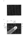
次に、図8を参照しながら、全体画像データ、部分画像データ、および座標データについて、例を挙げて説明する。図8(a)に示す画像データは、対象物がセンサ内蔵液晶パネル301上に置かれていないときに、センサ内蔵液晶パネル301全体をスキャンした結果として得られる画像データである。また、図8(b)に示す画像データは、ユーザが指でセンサ内蔵液晶パネル301をタッチしているときに、センサ内蔵液晶パネル301全体をスキャンした結果として得られる画像データである。
(Whole image data / Partial image data / Coordinate data)
Next, the whole image data, the partial image data, and the coordinate data will be described with reference to FIG. The image data shown in FIG. 8A is image data obtained as a result of scanning the entire sensor-equipped
ユーザが指でセンサ内蔵液晶パネル301をタッチしたとき、当該タッチした近傍の光センサ回路32が受光する光量が変化するため、当該光センサ回路32が出力する電圧に変化が生じ、その結果として、センサ制御部602が生成する画像データのうち、ユーザがタッチした部分の画素値の明度に変化が生じることとなる。
When the user touches the sensor built-in
図8(b)に示す画像データでは、図8(a)に示す画像データと比べると、ユーザの指に該当する部分の画素値の明度が高くなっている。そして、図8(b)に示す画像データにおいて、明度が所定の閾値より大きく変化している画素値を全て含む最小の矩形領域(領域PP)が、“部分画像データ”である。 In the image data shown in FIG. 8B, the brightness of the pixel value of the portion corresponding to the user's finger is higher than that in the image data shown in FIG. In the image data shown in FIG. 8B, the smallest rectangular area (area PP) that includes all pixel values whose lightness changes more than a predetermined threshold value is “partial image data”.
なお、領域APで示される画像データが、“全体画像データ”である。 The image data indicated by the area AP is “whole image data”.
また、部分画像データ(領域PP)の代表座標Zの、全体画像データ(領域AP)における座標データは(Xa,Ya)であり、部分画像データ(領域PP)における座標データは(Xp,Yp)である。 Also, the coordinate data in the whole image data (area AP) of the representative coordinates Z of the partial image data (area PP) is (Xa, Ya), and the coordinate data in the partial image data (area PP) is (Xp, Yp). It is.
なお、本発明において、上記の部分画像データに含まれる、明度が所定の閾値より大きく変化している画素からなる領域は選択領域360(図2参照)に相当し、代表座標Zは前記「選択位置」の一例に相当する。なお、「選択位置」は選択領域360内に含まれる一点の位置、或いは、選択領域360に含まれる全体又は一部領域の位置であればよく、特に代表座標Zのみに限定されるものではない。
In the present invention, an area made up of pixels whose brightness changes more than a predetermined threshold included in the partial image data corresponds to the selection area 360 (see FIG. 2), and the representative coordinate Z is the “selection”. It corresponds to an example of “position”. The “selection position” may be the position of one point included in the
また、データ表示/センサ装置100では、ユーザの使用時におけるセンサ内蔵液晶パネル301(図1、図2、図5参照)の左右方向をX軸、上下方向をY軸として座標軸が設定されており、当該XY座標軸は記憶部901(図5参照)に格納されている。すなわち、データ表示/センサ装置100では、その長手方向とY軸方向とが一致しており、幅方向とX軸方向とが一致している。また、データ表示/センサ装置100では、ユーザの使用時において、X軸は複数の入力キー350(図2参照)の横並び方向に一致し、Y軸は複数の入力キー350の縦並び方向に一致している。
In the data display /
なお、X軸とY軸との交点、すなわち座標軸の原点は、センサ内蔵液晶パネル301のパネル面の重心に固定してもよいが、例えば、上記選択位置の位置座標が原点となるように設定することもできる。
The intersection of the X axis and the Y axis, that is, the origin of the coordinate axis may be fixed at the center of gravity of the panel surface of the sensor-equipped
(センサ内蔵液晶パネルの構成)
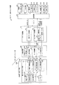
次に、図9を参照しながら、センサ内蔵液晶パネル301の構成、および、センサ内蔵液晶パネル301の周辺回路309の構成について説明する。図9は、表示/光センサ部300の要部、特に、センサ内蔵液晶パネル301の構成および周辺回路309の構成を示すブロック図である。
(Configuration of sensor built-in liquid crystal panel)
Next, the configuration of the sensor built-in
センサ内蔵液晶パネル301は、光透過率(輝度)を設定するための画素回路31、および、自身が受光した光の強度に応じた電圧を出力する光センサ回路32を備えている。なお、画素回路31は、赤色、緑色、青色のカラーフィルタのそれぞれに対応するR画素回路31r、G画素回路31g、B画素回路31bの総称として用いる。
The sensor built-in
画素回路31は、センサ内蔵液晶パネル301上の列方向(縦方向)にm個、行方向(横方向)に3n個配置される。そして、R画素回路31r、G画素回路31g、およびB画素回路31bの組が、行方向(横方向)に連続して配置される。この組が1つの画素を形成する。
The
画素回路31の光透過率を設定するには、まず、画素回路31に含まれるTFT(Thin Film Transistor)33のゲート端子に接続される走査信号線Giにハイレベル電圧(TFT33をオン状態にする電圧)を印加する。その後、R画素回路31rのTFT33のソース端子に接続されているデータ信号線SRjに、所定の電圧を印加する。同様に、G画素回路31gおよびB画素回路31bについても、光透過率を設定する。そして、これらの光透過率を設定することにより、センサ内蔵液晶パネル301上に画像が表示される。
In order to set the light transmittance of the
次に、光センサ回路32は、一画素毎に配置される。なお、R画素回路31r、G画素回路31g、およびB画素回路31bのそれぞれの近傍に1つずつ配置されてもよい。
Next, the
光センサ回路32にて光の強度に応じた電圧を出力させるためには、まず、コンデンサ35の一方の電極に接続されているセンサ読み出し線RWiと、フォトダイオード36のアノード端子に接続されているセンサリセット線RSiとに所定の電圧を印加する。この状態において、フォトダイオード36に光が入射されると、入射した光量に応じた電流がフォトダイオード36に流れる。そして、当該電流に応じて、コンデンサ35の他方の電極とフォトダイオード36のカソード端子との接続点(以下、接続ノードV)の電圧が低下する。そして、センサプリアンプ37のドレイン端子に接続される電圧印加線SDjに電源電圧VDDを印加すると、接続ノードVの電圧は増幅され、センサプリアンプ37のソース端子からセンシングデータ出力線SPjに出力される。そして、当該出力された電圧に基づいて、光センサ回路32が受光した光量を算出することができる。
In order for the
次に、センサ内蔵液晶パネル301の周辺回路である、液晶パネル駆動回路304、光センサ駆動回路305、およびセンサ出力アンプ44について説明する。
Next, the liquid crystal panel drive circuit 304, the optical
液晶パネル駆動回路304は、画素回路31を駆動するための回路であり、走査信号線駆動回路3041およびデータ信号線駆動回路3042を含んでいる。
The liquid crystal panel drive circuit 304 is a circuit for driving the
走査信号線駆動回路3041は、表示制御部601から受信したタイミング制御信号TC1に基づいて、1ライン時間毎に、走査信号線G1〜Gmの中から1本の走査信号線を順次選択し、該選択した走査信号線にハイレベル電圧を印加するとともに、その他の走査信号線にローレベル電圧を印加する。
The scanning signal
データ信号線駆動回路3042は、表示制御部601から受信した表示データD(DR、DG、およびDB)に基づいて、1ライン時間毎に、1行分の表示データに対応する所定の電圧を、データ信号線SR1〜SRn、SG1〜SGn、SB1〜SBnに印加する(線順次方式)。なお、データ信号線駆動回路3042は、点順次方式で駆動するものであってもよい。
Based on the display data D (DR, DG, and DB) received from the
光センサ駆動回路305は、光センサ回路32を駆動するための回路である。光センサ駆動回路305は、センサ制御部602から受信したタイミング制御信号TC2に基づいて、センサ読み出し信号線RW1〜RWmの中から、1ライン時間毎に1本ずつ選択したセンサ読み出し信号線に所定の読み出し用電圧を印加するとともに、その他のセンサ読み出し信号線には、所定の読み出し用電圧以外の電圧を印加する。また、同様に、タイミング制御信号TC2に基づいて、センサリセット信号線RS1〜RSmの中から、1ライン時間毎に1本ずつ選択したセンサリセット信号線に所定のリセット用電圧を印加するとともに、その他のセンサリセット信号線には、所定のリセット用電圧以外の電圧を印加する。
The optical
センシングデータ出力信号線SP1〜SPnはp個(pは1以上n以下の整数)のグループにまとめられ、各グループに属するセンシングデータ出力信号線は、時分割で順次オン状態になるスイッチ47を介して、センサ出力アンプ44に接続される。センサ出力アンプ44は、スイッチ47により接続されたセンシングデータ出力信号線のグループからの電圧を増幅し、センサ出力信号SS(SS1〜SSp)として、信号変換回路306へ出力する。
The sensing data output signal lines SP1 to SPn are grouped into p groups (p is an integer of 1 to n), and the sensing data output signal lines belonging to each group are connected via a
(データ表示/センサ装置のより詳細な構成)
次に、図10を参照しながら、データ表示/センサ装置100のより詳細な構成について説明する。なお、ここでは、説明を分かりやすくするために、主制御部800と表示/光センサ部300との間に位置するデータ処理部700および回路制御部600(図5参照)の動作については説明を省略する。ただし、正確には、データの表示および対象物のスキャンを行うにあたり、主制御部800の各部が、データ処理部700にコマンドを送信し、データ処理部700がコマンドに基づいて回路制御部600を制御し、回路制御部600が表示/光センサ部300に対して信号を送信する。また、主制御部800は、データ処理部700に対して送信したコマンドに対する応答として、データ処理部700から、全体画像データ、部分画像データ、および座標データを取得する。
(Data display / more detailed configuration of sensor device)
Next, a more detailed configuration of the data display /
図10は、本実施形態に係るデータ表示/センサ装置100の構成を主制御部800および記憶部901を中心に示すブロック図である。図10に示すように、主制御部800は、被指示画面表示制御部11、選択位置検出部(選択位置検出手段)12、補助画像表示制御部13、進入方向検出部(進入方向検出手段)14、および入力位置認識部(入力位置認識手段)15を備えている。また、記憶部901は、被指示画面データ記憶部21、補助画像データ記憶部23を備えている。
FIG. 10 is a block diagram showing the configuration of the data display /
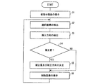
次に、図10及び図11を参照しながら、データ表示/センサ装置100の動作の一例について説明する。図11は、本実施形態に係るデータ表示/センサ装置100の動作を説明するフローチャートである。
Next, an example of the operation of the data display /
ステップS1では、データ表示/センサ装置100は、センサ内蔵液晶パネル301上に被指示画面、すなわち指64による入力を受付けるための入力キーを含んだ画面を表示する。一実施形態において、被指示画面表示制御部11が、センサ内蔵液晶パネル301に、複数の入力キー350によって構成されるスクリーンキーボード351を表示させる(図2も参照)。
In step S <b> 1, the data display /
詳しく述べれば、まず、被指示画面表示制御部11は、被指示画面データ記憶部21からデータを呼び出して、表示すべき画像データを取得する。被指示画面データ記憶部21から呼び出すデータは、例えば、各入力キー350の座標、寸法、ならびに画像データであり、すべての入力キー350の画像データをそれぞれの座標および寸法に基づいて合成することにより、表示すべき全体画像のデータを生成することができる。また、表示すべき全体画像(スクリーンキーボード351の全体画像)のデータをそのまま被指示画面データ記憶部21から呼び出してもよい。
More specifically, first, the instructed screen display control unit 11 retrieves data from the instructed screen
次に、被指示画面表示制御部11は、上記のように得た表示すべき全体画面のデータを表示データ処理部701に送るとともに、「表示パネル」を表示/光センサ部300とした上記コマンドをデータ処理部700に送る。データ処理部700は、上述したように、表示制御部601およびバックライト制御部603を制御してセンサ内蔵液晶パネル301上にスクリーンキーボード351を表示させる(図2、図5も参照)。
Next, the instructed screen display control unit 11 sends the data of the entire screen to be displayed obtained as described above to the display
なお、ステップS1は、必要に応じて開始されればよく、例えば、アプリケーションの開始とともに開始される。 Note that step S <b> 1 may be started as necessary, for example, when the application is started.
次に、ステップS2において、データ表示/センサ装置100は、センサ内蔵液晶パネル301上の、指64が指示する先の点の座標(「選択座標」と称する:図8(b)に示す代表座標Zに相当)を検出し、この選択座標を、指64により選択されたセンサ内蔵液晶パネル301上の領域の位置(選択位置)として認識する。一実施形態において、選択位置検出部12が、センサデータ処理部703から上記選択座標を取得して、当該選択座標を入力位置認識部15での認識処理に供する。
Next, in step S2, the data display /
詳しく述べれば、選択位置検出部12は、データ処理部700に対して、「データ種別」を”座標”、「データ取得タイミング」を、”イベント”とした上記コマンドを送る。選択位置検出部12は、上記コマンドの応答としてセンサデータ処理部703から得られた上記座標を、選択座標として取得し入力位置認識部15での認識処理に供する。なお、選択位置検出部12が、データ取得のタイミングおよび取得データの変化の判定を行なう場合には、上記コマンドの「データ取得タイミング」は、”オール”または”センス”としてもよい。
Specifically, the selected
なお、ステップS2は、ステップS1と同様、例えば、アプリケーションの開始とともに開始される。 Note that step S2 is started together with the start of the application, for example, similarly to step S1.
次に、ステップS3において、データ表示/センサ装置100は、センサ内蔵液晶パネル301に対する指64の進入方向を検出する。一実施形態において、進入方向検出部14が、センサデータ処理部703から全体画像データを取得し、当該全体画像データに基づいて指64の進入方向を検出する。
Next, in step S <b> 3, the data display /
詳しく述べれば、進入方向検出部14は、データ処理部700に対して、「データ種別」を”全体画像”、「データ取得タイミング」を、”イベント”とした上記コマンドを送る。進入方向検出部14は、上記コマンドの応答としてセンサデータ処理部703から得られた全体画像から、1)センサ内蔵液晶パネル301の表示面内(パネル面内)における指64の進入角α、及び2)センサ内蔵液晶パネル301の表示面内(パネル面内)における64の進入方向、を取得し、入力位置認識部15での認識処理に供する。
More specifically, the approach direction detection unit 14 sends the above command with “data type” as “whole image” and “data acquisition timing” as “event” to the
ここで、指64の進入方向は、上記全体画像に含まれる指64の画像の形状及び明度の相違から検知することができる。例えば、図8(b)の例においては、明度が所定の閾値より大きく変化している部分に含まれる代表座標Zを終点側とし、指64の画像の長手方向に沿う方向が、指64の進入方向となる(図8(b)中に矢印で示す)。
Here, the approach direction of the
進入方向検出部14は、必要に応じてさらに、指64の進入方向が、センサ内蔵液晶パネル301のパネル面内における特定方向又は当該特定方向と反対方向の何れにより近い方向であるかを検出して、指64の進入方向を大きく二方向に分類する。基準となる特定方向は予め定めておき、記憶部901に格納しておけばよい。
If necessary, the approach direction detection unit 14 further detects whether the approach direction of the
例えば、図8(b)の例においては、ユーザにとりセンサ内蔵液晶パネル301の左側端から右向きの方向(X軸の+方向)が特定方向であり、指64の進入方向は特定方向に対して鋭角に交わり、特定方向と反対方向に対して鈍角に交わる。よって、指64の進入方向は特定方向により近いと検出される。
For example, in the example of FIG. 8B, for the user, the direction from the left end of the sensor built-in
また、指64の進入角αは、データ表示/センサ装置100において予め定めた基準軸と、上記進入方向とのなす角(ただし、0度以上90度以下の角を指す)として検知することができる。例えば、図8(b)の例においては、予め定めた上記基準軸はX軸であり、当該X軸と指64の進入方向とのなす角を座標計算により算出して、進入角αを検知する。
Further, the approach angle α of the
なお、進入方向検出部14が、データ取得のタイミングおよび取得データの変化の判定を行なう場合には、上記コマンドの「データ取得タイミング」は、”オール”または”センス”としてもよい。 When the approach direction detection unit 14 determines the data acquisition timing and the change in the acquired data, the “data acquisition timing” of the command may be “all” or “sense”.
なお、ステップS3は、ステップS1と同様、例えば、アプリケーションの開始とともに開始される。また、ステップS2とステップS3とは実行順序を入れ替えることもできる。 Note that step S3 is started together with the start of the application, for example, similarly to step S1. Further, the order of execution of step S2 and step S3 can be switched.
次に、ステップS4において、データ表示/センサ装置100は、ステップS2にて検出された選択座標に対して補正を行うか否かを判定する。一実施形態において、入力位置認識部15が、1)上記進入角αが45度以下であるか否か、又は、2)上記選択座標が、何れかの入力キー350の中心から所定の距離以内にあるか否か(すなわち、指64により選択された領域の位置が入力キーの中心から外れているか否か)、の少なくとも一方を基準として補正の要否を判定する。
Next, in step S4, the data display /
より具体的には、進入角αが45度以下の場合には上記補正を行い、進入角αが45度を超える場合には補正を行わないと判定する。また、上記選択座標が何れかの入力キー350の中心から所定の距離以内にない場合には上記補正を行い、当該所定の距離以内にある場合には上記補正を行わないと判定する。
More specifically, when the approach angle α is 45 degrees or less, the above correction is performed, and when the approach angle α exceeds 45 degrees, it is determined that the correction is not performed. If the selected coordinate is not within a predetermined distance from the center of any of the
なお、上記選択座標と入力キー350の中心との距離は、例えば、入力位置認識部15が、被指示画面データ記憶部21より各入力キー350の座標を呼び出し、選択座標と比較をすることで求めることができる。
The distance between the selected coordinates and the center of the
次に、ステップS4にて補正「要」と判定された場合には、ステップS5に進む。一方、ステップS4にて補正「不要」と判定された場合には、後述するステップS6に進む。 Next, when it is determined that the correction is “necessary” in step S4, the process proceeds to step S5. On the other hand, if it is determined in step S4 that the correction is “unnecessary”, the process proceeds to step S6 described later.
ステップS5において、データ表示/センサ装置100は、上記選択座標に対して行う補正の量(補正量)と方向(補正の方向)とを決定する。
In step S5, the data display /
一実施形態において、入力位置認識部15は、進入方向検出部14が検出した指64の進入方向に応じて補正の方向を決定する。具体的には、例えば、入力位置認識部15は、1)上記進入方向に沿う方向、又は、2)予め定めた上記特定方向とその反対方向とのうち、指64の進入方向により近い方向(図8(b)の例では、特定方向たるX軸の+方向)、を補正の方向として決定する。
In one embodiment, the input
また、入力位置認識部15は、決定した補正の方向に沿ってどの程度の補正量で補正を行うべきかを決定する。当該補正量は、固定量であってもよく、指64の進入角αにより変動する量であってもよい。なお、何れの場合でも、補正量は、上記補正の方向に沿って隣接する入力キー350・350間のキーピッチの半分以下であることが好ましい。
Further, the input
また、進入角αにより補正量を変動させる場合、上記補正の方向に沿って隣接する入力キー間のキーピッチをAとした場合に、補正量=A×進入角α÷90の関係式を満たすように決定することが好ましい。ただし、この例示では、進入角αが45度以下の場合に補正を行うため、上記関係式における進入角αは0度〜45度以下の角度を表す。 Further, when the correction amount is varied depending on the approach angle α, the relational expression of correction amount = A × entrance angle α ÷ 90 is satisfied, where A is the key pitch between adjacent input keys along the correction direction. It is preferable to determine this. However, in this example, since the correction is performed when the approach angle α is 45 degrees or less, the approach angle α in the above relational expression represents an angle of 0 degrees to 45 degrees or less.
さらに、ステップS5において、入力位置認識部15は、決定した補正量と補正の方向とに基づいて上記選択座標に対する補正を行い、当該補正後の位置を、センサ内蔵液晶パネル301に対する指64の入力位置として認識する。そして、この認識結果を、データ処理部700での処理に供する。
Further, in step S5, the input
次に、ステップS6において、データ表示/センサ装置100は、センサ内蔵液晶パネル301上における指64の入力位置にポインタ361を表示する。一実施形態において、補助画像表示制御部13が、補助画像データ記憶部23から表示すべき補助画像(ポインタ361)の画像データを呼び出し、当該画像データをデータ処理部700に供する。
Next, in step S <b> 6, the data display /
データ処理部700では、ポインタ361の画像データと、スクリーンキーボード351の画像データとを周知の画像合成技術により合成し、センサ内蔵液晶パネル301上に、入力位置認識部15により認識された入力位置を中心点としたポインタ361を表示する。
In the
ここで、ポインタ361の中心点となる上記入力位置とは、ステップS4において補正が「要」と判定された場合には、入力位置認識部15が入力位置と認識した補正後の位置である。一方、ステップS4において補正が「不要」と判定された場合は、指64による選択位置(すなわち、代表座標Z)自身が上記入力位置となる。
Here, the input position serving as the center point of the
以降は、ステップS2に戻り、ユーザの新たな指示を待つ。 Thereafter, the process returns to step S2 and waits for a new instruction from the user.
なお、上記ステップS1において表示する被指示画面は、スクリーンキーボード351である必要はなく、種々の入力キーとすることができる。例えば、それぞれ特定の機能(例えば、OKボタン、キャンセルボタンなど)に対応する入力キーを表示させてもよい。
The instructed screen displayed in step S1 does not need to be the
また、ここでは、センサ内蔵液晶パネル301上にスクリーンキーボード351が液晶表示される形態を例示したが、センサ内蔵液晶パネルの面内に、少なくとも一部の入力キーを予めプリントした構成であってもよい。特に、文字、又は一桁の数字のような汎用される入力キーのみを予めプリントした構成であってもよい。なお、予めプリントした入力キーを用いる場合にはステップS1は省略される。
In addition, here, the
また、ここでは、ステップS4において位置補正の要否を判定する形態を例示したが、S4を省略して、常時、位置補正を行う構成とすることもできる。この場合、位置補正の有無による入力のブレが生じないため、ユーザにとり好ましい場合もある。 In addition, here, the mode of determining whether or not position correction is necessary in step S4 is exemplified, but it is also possible to omit S4 and always perform position correction. In this case, input blur due to the presence or absence of position correction does not occur, which may be preferable for the user.
また、ここでは、ステップS6において、ユーザを補助するための補助画像(円形のポインタ361)を表示する形態を例示したが、表示されるポインタの形状・大きさなどは特に限定されるものではない。また、場合によっては、S6を省略してもよい。 In addition, here, in step S6, an example in which an auxiliary image (circular pointer 361) for assisting the user is displayed is illustrated, but the shape and size of the displayed pointer are not particularly limited. . In some cases, S6 may be omitted.
(補正の方向、及び補正量の決定の詳細の一例)
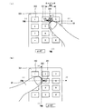
以下、上記ステップS5にて説明した、選択座標に対して行う補正の量(補正量)と補正の方向との決定の一例について、図12(a)・(b)に基づき具体的に説明する。
(Example of details of correction direction and correction amount determination)
Hereinafter, an example of the determination of the correction amount (correction amount) and the correction direction performed on the selected coordinates described in step S5 will be specifically described with reference to FIGS. 12 (a) and 12 (b). .
なお、図12(a)・(b)に示す例ではいずれも、ユーザにとり当該センサ内蔵液晶パネル301のパネル面内における左側端から右向きの方向(図中のX軸の+方向)を特定方向、右側端から左向きの方向(図中のX軸の−方向)を特定方向と反対方向とし、指64の進入方向が、上記特定方向と反対方向との何れにより近いか分類をする。すなわち、指64が、センサ内蔵液晶パネル301の右側から(上記反対方向により近い方向から)進入しているのか、或いは左側から(上記特定方向により近い方向から)進入しているのか大きく二種類に分類をする。
In each of the examples shown in FIGS. 12 (a) and 12 (b), the direction from the left end on the panel surface of the sensor-equipped
また、進入角αの算出のために予め定めた基準軸はX軸であり、当該X軸と指64の進入方向とのなす角(0度以上で90度以下)が進入角αとなる。
Further, the reference axis predetermined for calculating the approach angle α is the X axis, and an angle (0 degree or more and 90 degrees or less) formed by the X axis and the approach direction of the
さらに、X軸方向に隣接する入力キー間のキーピッチは8mmである。 Furthermore, the key pitch between the input keys adjacent in the X-axis direction is 8 mm.
なお、図12(a)・(b)では、説明の便宜上、選択領域360と指64の先端とを互いにずれた状態で示しているが、実際には両者は重複している。
In FIGS. 12A and 12B, for convenience of explanation, the
図12(a)に示す例では、ユーザが右手にてデータ表示/センサ装置100のグリップ部100a(図1参照)を持ち、右手の親指64にて複数の入力キー350に対する操作を行っている。また、指64は、ユーザから見てセンサ内蔵液晶パネル301の右側から進入している。さらに、進入角αは45度である。
In the example shown in FIG. 12A, the user holds the
この場合、入力位置認識部15は、上記特定方向とその反対方向とのうち、指64の進入方向により近い方向である反対方向(X軸の−方向)を補正の方向として決定する。
In this case, the input
さらに、入力位置認識部15は、決定した補正の方向に沿ってどの程度の補正量で補正を行うべきかを決定する。ここでは、選択位置検出部12が検出した選択座標(図8(b)に示す代表座標Z)をP、入力位置認識部15による補正後の位置をP’、上記補正の方向(X軸の−方向)に沿って隣接する入力キー350・350間のキーピッチをAとした場合に、補正量=A×進入角α÷90という関係を満足するように当該補正量を決定する。
Furthermore, the input
ここで、キーピッチAは8mm、進入角αは45度であるから、補正量は8×45÷90=4(単位:mm)となる。すなわち、入力位置認識部15は、指64により現実に選択されたセンサ内蔵液晶パネル301上の領域の位置を表す選択座標(すなわちP)に対して、X軸上の−方向に4mmの補正を行った補正後の位置P’を、当該センサ内蔵液晶パネル301に対する入力位置として認識する。
Here, since the key pitch A is 8 mm and the approach angle α is 45 degrees, the correction amount is 8 × 45 ÷ 90 = 4 (unit: mm). That is, the input
一方、図12(b)に示す例では、ユーザが左手にてデータ表示/センサ装置100のグリップ部100a(図1参照)を持ち、左手の親指64にて複数の入力キー350に対する操作を行っている。また、指64は、ユーザから見てセンサ内蔵液晶パネル301の左側から進入している。さらに、進入角αは30度である。
On the other hand, in the example shown in FIG. 12B, the user holds the
この場合、入力位置認識部15は、上記特定方向とその反対方向とのうち、指64の進入方向により近い方向である特定方向(X軸の+方向)を補正の方向として決定する。
In this case, the input
さらに、入力位置認識部15は、決定した補正の方向に沿ってどの程度の補正量で補正を行うべきかを決定する。ここでは、選択位置検出部12が検出した選択座標(図8(b)に示す代表座標Z)をP、入力位置認識部15による補正後の位置をP’、上記補正の方向(X軸の+方向)に沿って隣接する入力キー350・350間のキーピッチをAとした場合に、補正量=A×進入角α÷90という関係を満足するように当該補正量を決定する。
Furthermore, the input
ここで、キーピッチAは8mm、進入角αは30度であるから、補正量は8×30÷90≒2.6(単位:mm)となる。すなわち、入力位置認識部15は、指64により現実に選択されたセンサ内蔵液晶パネル301上の領域の位置を表す選択座標(すなわちP)に対して、X軸上の+方向に2.6mmの補正を行った補正後の位置P’を、当該センサ内蔵液晶パネル301に対する入力位置として認識する。
Here, since the key pitch A is 8 mm and the approach angle α is 30 degrees, the correction amount is 8 × 30 ÷ 90≈2.6 (unit: mm). That is, the input
(補正の方向、及び補正量の決定の詳細の他の例)
以下、上記ステップS5にて説明した、選択座標に対して行う補正の量(補正量)と補正の方向との決定の他の例について、図13に基づき具体的に説明する。
(Other examples of details of correction direction and correction amount determination)
Hereinafter, another example of the determination of the correction amount (correction amount) and the correction direction performed on the selected coordinate described in step S5 will be specifically described with reference to FIG.
図13に示す例では、進入角αの算出のために予め定めた基準軸はX軸であり、当該X軸と指64の進入方向とのなす角(0度以上で90度以下)が進入角αとなる。さらに、X軸方向に隣接する入力キー間のキーピッチは8mmである。また、図13では、説明の便宜上、選択領域360と指64の先端とを互いにずれた状態で示しているが、実際には両者は重複している。
In the example shown in FIG. 13, the reference axis predetermined for calculating the approach angle α is the X axis, and an angle (0 ° or more and 90 ° or less) formed by the X axis and the approach direction of the
この例では、ユーザが右手にてデータ表示/センサ装置100のグリップ部100a(図1参照)を持ち、右手の親指64にて複数の入力キー350に対する操作を行っている。また、指64は、図中、矢印で示す方向(進入方向)からセンサ内蔵液晶パネル301の表示面内に進入し、当該指64の進入角αは45度である。
In this example, the user holds the
この例では、入力位置認識部15は、矢印で示す指64の進入方向に沿う方向を、補正の方向として決定する。
In this example, the input
さらに、入力位置認識部15は、決定した補正の方向に沿ってどの程度の補正量で補正を行うべきかを決定する。ここでは、選択位置検出部12が検出した選択座標(図8(b)に示す代表座標Z)をP、入力位置認識部15による補正後の位置をP’、X軸方向に隣接する入力キー350・350間のキーピッチをAとした場合に、補正量=A×進入角α÷90という関係を満足するように当該補正量を決定する。
Furthermore, the input
ここで、キーピッチAは8mm、進入角αは45度であるから、補正量は8×45÷90=4(単位:mm)となる。すなわち、入力位置認識部15は、指64により現実に選択されたセンサ内蔵液晶パネル301上の領域の位置を表す選択座標(すなわちP)に対して、指64の進入方向に沿って4mmの補正を行った補正後の位置P’を、当該センサ内蔵液晶パネル301に対する入力位置として認識する。
Here, since the key pitch A is 8 mm and the approach angle α is 45 degrees, the correction amount is 8 × 45 ÷ 90 = 4 (unit: mm). That is, the input
なお、図13の例においては、補正の方向(指の進入方向)に沿って隣接する入力キー350・350(「2」のナンバーキー及び「6」のナンバーキー)間の距離(約11mm)を、上記キーピッチAとして用いてもよい。
In the example of FIG. 13, the distance (about 11 mm) between the
(プログラムおよび記録媒体)
最後に、データ表示/センサ装置100に含まれている回路制御部600、データ処理部700、および主制御部800は、ハードウェアロジックによって構成すればよい。または、次のように、CPU(Central Processing Unit)を用いてソフトウェアによって実現してもよい。
(Program and recording medium)
Finally, the
すなわち、回路制御部600、データ処理部700および主制御部800は、各機能を実現するプログラムの命令を実行するMPUなどのCPU、このプログラムを格納したROM(Read Only Memory)、上記プログラムを実行可能な形式に展開するRAM(Random Access Memory)、および、上記プログラムおよび各種データを格納するメモリなどの記憶装置(記録媒体)を備えている。
That is, the
そして、本発明の目的は、回路制御部600、データ処理部700および主制御部800のプログラムメモリに固定的に担持されている場合に限らず、上記プログラムのプログラムコード(実行形式プログラム、中間コードプログラム、または、ソースプログラム)を記録した記録媒体をデータ表示/センサ装置100に供給し、データ表示/センサ装置100が上記記録媒体に記録されている上記プログラムコードを読み出して実行することによっても、達成可能である。
The object of the present invention is not limited to the case where the program memory of the
上記記録媒体は、特定の構造または種類のものに限定されない。すなわちこの記録媒体は、たとえば、磁気テープやカセットテープなどのテープ系、フロッピー(登録商標)ディスク/ハードディスクなどの磁気ディスクやCD−ROM/MO/MD/DVD/CD−Rなどの光ディスクを含むディスク系、ICカード(メモリカードを含む)/光カードなどのカード系、あるいはマスクROM/EPROM/EEPROM/フラッシュROMなどの半導体メモリ系などとすることができる。 The recording medium is not limited to a specific structure or type. That is, the recording medium includes, for example, a tape system such as a magnetic tape and a cassette tape, a magnetic disk such as a floppy (registered trademark) disk / hard disk, and an optical disk such as a CD-ROM / MO / MD / DVD / CD-R. System, a card system such as an IC card (including a memory card) / optical card, or a semiconductor memory system such as a mask ROM / EPROM / EEPROM / flash ROM.
また、回路制御部600、データ処理部700および主制御部800(またはデータ表示/センサ装置100)を通信ネットワークと接続可能に構成しても、本発明の目的を達成できる。この場合、上記のプログラムコードを、通信ネットワークを介して回路制御部600、データ処理部700および主制御部800に供給する。この通信ネットワークは回路制御部600、データ処理部700および主制御部800にプログラムコードを供給できるものであればよく、特定の種類または形態に限定されない。たとえばインターネット、イントラネット、エキストラネット、LAN、ISDN、VAN、CATV通信網、仮想専用網(Virtual Private Network)、電話回線網、移動体通信網、衛星通信網などであればよい。
The object of the present invention can be achieved even if the
この通信ネットワークを構成する伝送媒体も、プログラムコードを伝送可能な任意の媒体であればよく、特定の構成または種類のものに限定されない。たとえばIEEE1394、USB、電力線搬送、ケーブルTV回線、電話線、ADSL(Asymmetric Digital Subscriber Line)回線などの有線でも、IrDAやリモコンのような赤外線、Bluetooth(登録商標)、802.11無線、HDR、携帯電話網、衛星回線、地上波デジタル網などの無線でも利用可能である。なお本発明は、上記プログラムコードが電子的な伝送で具現化された、搬送波に埋め込まれたコンピュータデータ信号の形態でも実現され得る。 The transmission medium constituting the communication network may be any medium that can transmit the program code, and is not limited to a specific configuration or type. For example, even with wired lines such as IEEE 1394, USB, power line carrier, cable TV line, telephone line, ADSL (Asymmetric Digital Subscriber Line) line, infrared rays such as IrDA and remote control, Bluetooth (registered trademark), 802.11 wireless, HDR, mobile phone It can also be used by radio such as a telephone network, a satellite line, and a terrestrial digital network. The present invention can also be realized in the form of a computer data signal embedded in a carrier wave in which the program code is embodied by electronic transmission.
以上、本発明を実施形態に基づいて具体的に説明したが、本発明は、上述した実施形態に限定されるものではなく、請求項に示した範囲において種々の変更が可能であり、異なる実施形態にそれぞれ開示された技術的手段を適宜組み合わせて得られる実施形態についても本発明の技術的範囲に含まれる。 The present invention has been specifically described above based on the embodiments. However, the present invention is not limited to the above-described embodiments, and various modifications are possible within the scope of the claims, and different implementations are possible. Embodiments obtained by appropriately combining the technical means disclosed in each form are also included in the technical scope of the present invention.
本発明は、各種情報機器において利用することができる。 The present invention can be used in various information devices.
12 選択位置検出部(選択位置検出手段)
14 進入方向検出部(進入方向検出手段)
15 入力位置認識部(入力位置認識手段)
64 指(対象物)
100 データ表示/センサ装置(像検知装置)
301 センサ内蔵液晶パネル(面状部材)
350 入力キー
360 選択領域(対象物により選択された面状部材上の領域)
361 ポインタ
12 Selection position detection unit (selection position detection means)
14 Approach direction detection part (entrance direction detection means)
15 Input position recognition unit (input position recognition means)
64 fingers (object)
100 Data display / sensor device (image detection device)
301 Liquid crystal panel with built-in sensor (planar member)
350
361 pointer
Claims (10)
上記面状部材が検知した対象物の像に基づいて、当該対象物により選択された当該面状部材上の領域の位置を検出する選択位置検出手段と、
上記面状部材が検知した対象物の像から当該面状部材に対する対象物の進入方向を検出する進入方向検出手段と、
上記選択位置検出手段が検出した上記領域の位置に対する補正を行い、当該補正後の位置を面状部材に対する入力位置として認識する入力位置認識手段とを備え、
上記入力位置認識手段は、進入方向検出手段が検出した上記進入方向に応じて上記補正の方向を決定する、
ことを特徴とする像検知装置。 A planar member for detecting an image of an object located in the vicinity;
Selection position detecting means for detecting the position of the area on the planar member selected by the object based on the image of the object detected by the planar member;
An approach direction detecting means for detecting an approach direction of the object with respect to the planar member from an image of the object detected by the planar member;
An input position recognition unit that performs correction on the position of the region detected by the selection position detection unit and recognizes the corrected position as an input position with respect to the planar member;
The input position recognizing means determines the correction direction according to the approach direction detected by the approach direction detecting means;
An image detection apparatus characterized by that.
前記入力位置認識手段は、前記選択位置検出手段が検出した領域の位置を上記進入方向に沿う方向に補正することを特徴とする請求項1に記載の像検知装置。 The approach direction detecting means detects the approach direction of the object in the in-plane direction of the planar member,
The image detection apparatus according to claim 1, wherein the input position recognition unit corrects the position of the area detected by the selection position detection unit in a direction along the approach direction.
前記入力位置認識手段は、上記対象物の進入方向が上記特定方向により近い場合は、前記領域の位置を特定方向に沿って補正し、上記対象物の進入方向が特定方向と反対方向により近い場合は、前記領域の位置を当該反対方向に沿って補正することを特徴とする請求項1に記載の像検知装置。 The approach direction detecting means detects whether the approach direction of the object in the in-plane direction of the planar member is closer to a specific direction in the plane or a direction opposite to the specific direction,
The input position recognition unit corrects the position of the region along the specific direction when the approach direction of the object is closer to the specific direction, and the approach direction of the object is closer to a direction opposite to the specific direction. The image detecting apparatus according to claim 1, wherein the position of the region is corrected along the opposite direction.
前記入力位置認識手段は、上記進入角αが45度以下の場合に前記補正を行うことを特徴とする請求項1から3の何れか一項に記載の像検知装置。 The approach direction detecting means detects an approach angle α of the object with respect to a predetermined reference axis,
4. The image detection apparatus according to claim 1, wherein the input position recognition unit performs the correction when the approach angle α is 45 degrees or less. 5.
前記選択位置検出手段が検出した前記領域の位置が、入力キーの中心から外れている場合に、前記入力位置認識手段による補正を行うことを特徴とする、請求項1から5の何れか一項に記載の像検知装置。 An input key is provided on the planar member,
6. The correction by the input position recognition unit is performed when the position of the region detected by the selection position detection unit is out of the center of the input key. 6. The image detection apparatus described in 1.
隣接する入力キー間のキーピッチをAとした場合に、
前記入力位置認識手段による補正は、その補正量がA×進入角α÷90の関係式を満たすように行われることを特徴とする請求項4に記載の像検知装置。 A plurality of input keys are provided on the planar member,
When the key pitch between adjacent input keys is A,
The image detection apparatus according to claim 4, wherein the correction by the input position recognition unit is performed so that the correction amount satisfies a relational expression of A × entrance angle α ÷ 90.
上記面状部材が検知した対象物の像に基づいて、当該対象物により選択された当該面状部材上の領域の位置を検出する選択位置検出工程と、
上記面状部材が検知した対象物の像から当該面状部材に対する対象物の進入方向を検出する進入方向検出工程と、
上記進入方向検出工程にて検出した対象物の進入方向に応じて、上記選択位置検出工程にて検出した上記領域の位置に対する補正の方向を決定して、当該領域の位置に対する補正を行い、当該補正後の位置を面状部材に対する入力位置として認識する入力位置認識工程と、
を含むことを特徴とする入力位置の認識方法。 A method for recognizing an input position in an image detection device including a planar member for detecting an image of an object located in the vicinity,
A selection position detecting step for detecting a position of a region on the planar member selected by the target object based on an image of the target object detected by the planar member;
An approach direction detecting step of detecting an approach direction of the object with respect to the planar member from an image of the object detected by the planar member;
According to the approach direction of the object detected in the approach direction detection step, a correction direction for the position of the region detected in the selected position detection step is determined, and the position of the region is corrected. An input position recognition step for recognizing the corrected position as an input position for the planar member;
An input position recognition method comprising:
Priority Applications (1)
| Application Number | Priority Date | Filing Date | Title |
|---|---|---|---|
| JP2008289925A JP2010117841A (en) | 2008-11-12 | 2008-11-12 | Image detection device, recognition method of input position and program |
Applications Claiming Priority (1)
| Application Number | Priority Date | Filing Date | Title |
|---|---|---|---|
| JP2008289925A JP2010117841A (en) | 2008-11-12 | 2008-11-12 | Image detection device, recognition method of input position and program |
Publications (1)
| Publication Number | Publication Date |
|---|---|
| JP2010117841A true JP2010117841A (en) | 2010-05-27 |
Family
ID=42305491
Family Applications (1)
| Application Number | Title | Priority Date | Filing Date |
|---|---|---|---|
| JP2008289925A Pending JP2010117841A (en) | 2008-11-12 | 2008-11-12 | Image detection device, recognition method of input position and program |
Country Status (1)
| Country | Link |
|---|---|
| JP (1) | JP2010117841A (en) |
Cited By (3)
| Publication number | Priority date | Publication date | Assignee | Title |
|---|---|---|---|---|
| JP2013012021A (en) * | 2011-06-29 | 2013-01-17 | Sony Corp | Information processing apparatus, information processing method, program and remote operation system |
| JP2013222290A (en) * | 2012-04-16 | 2013-10-28 | Fuji Xerox Co Ltd | Touch panel device and program |
| US9323419B2 (en) | 2011-12-07 | 2016-04-26 | Denso Corporation | Input apparatus |
-
2008
- 2008-11-12 JP JP2008289925A patent/JP2010117841A/en active Pending
Cited By (3)
| Publication number | Priority date | Publication date | Assignee | Title |
|---|---|---|---|---|
| JP2013012021A (en) * | 2011-06-29 | 2013-01-17 | Sony Corp | Information processing apparatus, information processing method, program and remote operation system |
| US9323419B2 (en) | 2011-12-07 | 2016-04-26 | Denso Corporation | Input apparatus |
| JP2013222290A (en) * | 2012-04-16 | 2013-10-28 | Fuji Xerox Co Ltd | Touch panel device and program |
Similar Documents
| Publication | Publication Date | Title |
|---|---|---|
| JP5367339B2 (en) | MENU DISPLAY DEVICE, MENU DISPLAY DEVICE CONTROL METHOD, AND MENU DISPLAY PROGRAM | |
| JP2010140300A (en) | Display, control method, control program and recording medium | |
| JP5095574B2 (en) | Image display / image detection apparatus, image display method, image display program, and recording medium recording the program | |
| JP2010186442A (en) | Input device and input control method | |
| JP2010122972A (en) | Image display/detection device, selection method, and program | |
| JP5306780B2 (en) | Input device | |
| JP5254753B2 (en) | Numerical input device, numerical input method, numerical input program, and computer-readable recording medium | |
| JP2010117841A (en) | Image detection device, recognition method of input position and program | |
| JP2010109467A (en) | Image display/image detection apparatus | |
| JP2010204945A (en) | Input device and input method | |
| JP5567776B2 (en) | Color detection / color output device, color detection / color output program, computer-readable recording medium, and color detection / color output method | |
| JP2010119064A (en) | Color detection device, color detection program, computer readable recording medium, and color detection method | |
| JP2010122383A (en) | Display apparatus | |
| WO2011121842A1 (en) | Display device with input unit, control method for same, control program and recording medium | |
| JP2010118018A (en) | Position identifying device, position identification program, computer-readable storage medium, and position identification method | |
| WO2010050567A1 (en) | Data transmission support device, electronic equipment and data transmission support device control method | |
| JP2010128566A (en) | Image detection device, recognition method for input region, and program | |
| JP2010108446A (en) | Information processor, control method of information processor, and information processing program | |
| JP2010160689A (en) | Input device and method of controlling the same | |
| JP5171572B2 (en) | Image display device, control method for image display device, program, and recording medium | |
| JP2010092272A (en) | Image display/image detection device, auxiliary image display method, and program | |
| JP2010109947A (en) | Processing execution command device, electronic equipment, and method of controlling processing execution command device | |
| JP2010062938A (en) | Image display/image detection apparatus | |
| JP2010118016A (en) | Input device, input method, input program, and computer-readable recording medium | |
| JP2010140410A (en) | Mobile apparatus and method of controlling the same |