JP2010112595A - Filter and air conditioning device provided with the same - Google Patents

Filter and air conditioning device provided with the same Download PDF

Info

Publication number
JP2010112595A
JP2010112595A JP2008283944A JP2008283944A JP2010112595A JP 2010112595 A JP2010112595 A JP 2010112595A JP 2008283944 A JP2008283944 A JP 2008283944A JP 2008283944 A JP2008283944 A JP 2008283944A JP 2010112595 A JP2010112595 A JP 2010112595A
Authority
JP
Japan
Prior art keywords
filter
frame
surface side
uneven
dust
Prior art date
Legal status (The legal status is an assumption and is not a legal conclusion. Google has not performed a legal analysis and makes no representation as to the accuracy of the status listed.)
Granted
Application number
JP2008283944A
Other languages
Japanese (ja)
Other versions
JP4456168B1 (en
Inventor
Yuji Uehara
雄二 上原
Current Assignee (The listed assignees may be inaccurate. Google has not performed a legal analysis and makes no representation or warranty as to the accuracy of the list.)
Sharp Corp
Original Assignee
Sharp Corp
Priority date (The priority date is an assumption and is not a legal conclusion. Google has not performed a legal analysis and makes no representation as to the accuracy of the date listed.)
Filing date
Publication date
Application filed by Sharp Corp filed Critical Sharp Corp
Priority to JP2008283944A priority Critical patent/JP4456168B1/en
Priority to CN200980142648XA priority patent/CN102203516B/en
Priority to PCT/JP2009/064933 priority patent/WO2010052965A1/en
Application granted granted Critical
Publication of JP4456168B1 publication Critical patent/JP4456168B1/en
Publication of JP2010112595A publication Critical patent/JP2010112595A/en
Expired - Fee Related legal-status Critical Current
Anticipated expiration legal-status Critical

Links

Images

Classifications

    • FMECHANICAL ENGINEERING; LIGHTING; HEATING; WEAPONS; BLASTING
    • F24HEATING; RANGES; VENTILATING
    • F24FAIR-CONDITIONING; AIR-HUMIDIFICATION; VENTILATION; USE OF AIR CURRENTS FOR SCREENING
    • F24F13/00Details common to, or for air-conditioning, air-humidification, ventilation or use of air currents for screening
    • F24F13/28Arrangement or mounting of filters
    • BPERFORMING OPERATIONS; TRANSPORTING
    • B01PHYSICAL OR CHEMICAL PROCESSES OR APPARATUS IN GENERAL
    • B01DSEPARATION
    • B01D46/00Filters or filtering processes specially modified for separating dispersed particles from gases or vapours
    • B01D46/0052Filters or filtering processes specially modified for separating dispersed particles from gases or vapours with filtering elements moving during filtering operation
    • B01D46/0054Filters or filtering processes specially modified for separating dispersed particles from gases or vapours with filtering elements moving during filtering operation with translational movement
    • BPERFORMING OPERATIONS; TRANSPORTING
    • B01PHYSICAL OR CHEMICAL PROCESSES OR APPARATUS IN GENERAL
    • B01DSEPARATION
    • B01D46/00Filters or filtering processes specially modified for separating dispersed particles from gases or vapours
    • B01D46/10Particle separators, e.g. dust precipitators, using filter plates, sheets or pads having plane surfaces
    • BPERFORMING OPERATIONS; TRANSPORTING
    • B01PHYSICAL OR CHEMICAL PROCESSES OR APPARATUS IN GENERAL
    • B01DSEPARATION
    • B01D46/00Filters or filtering processes specially modified for separating dispersed particles from gases or vapours
    • B01D46/66Regeneration of the filtering material or filter elements inside the filter
    • B01D46/68Regeneration of the filtering material or filter elements inside the filter by means acting on the cake side involving movement with regard to the filter elements
    • B01D46/681Regeneration of the filtering material or filter elements inside the filter by means acting on the cake side involving movement with regard to the filter elements by scrapers, brushes or the like
    • BPERFORMING OPERATIONS; TRANSPORTING
    • B01PHYSICAL OR CHEMICAL PROCESSES OR APPARATUS IN GENERAL
    • B01DSEPARATION
    • B01D2273/00Operation of filters specially adapted for separating dispersed particles from gases or vapours
    • B01D2273/14Filters which are moved between two or more positions, e.g. by turning, pushing
    • BPERFORMING OPERATIONS; TRANSPORTING
    • B01PHYSICAL OR CHEMICAL PROCESSES OR APPARATUS IN GENERAL
    • B01DSEPARATION
    • B01D2279/00Filters adapted for separating dispersed particles from gases or vapours specially modified for specific uses
    • B01D2279/50Filters adapted for separating dispersed particles from gases or vapours specially modified for specific uses for air conditioning

Abstract

<P>PROBLEM TO BE SOLVED: To provide a filter which can be installed to a cabinet without operation for confirming the direction of the filter. <P>SOLUTION: In the filters 10, 11, an irregular part 43 to be meshed with a drive device 41 for moving the filters 10, 11 is formed along a filter moving direction. The irregular part 43 includes a projection part on the other surface side of a recessed part formed on one surface side of the filters 10, 11, and a recessed part on the other surface side of a projection part formed on one surface side of the filters, so that the one surface side and the other surface side of the filters have the same irregular shape. <P>COPYRIGHT: (C)2010,JPO&INPIT

Description

本発明は、空気調節装置等に使用するフィルター及びそれを用いた空気調節装置に関するものである。   The present invention relates to a filter used in an air conditioner or the like and an air conditioner using the same.

従来、空気調和機、加湿機、除湿機、空気清浄機、暖房機等の空気調節装置には、空気中の塵埃を除去するための集塵フィルターが搭載されているが、集塵フィルターに付着した塵埃の清掃に手間がかかり、また衛生的でないという問題が生じていた。   Conventionally, air conditioners such as air conditioners, humidifiers, dehumidifiers, air purifiers, and heaters are equipped with dust collection filters to remove dust in the air, but they adhere to the dust collection filters. It takes time and effort to clean the dust, and there is a problem that it is not hygienic.

この問題を解決するものとして、例えば、特許文献1や特許文献2に示すように、吸込口と吹出口とを備えたキャビネット内に、摺動自在に装着されたフィルターと、同フィルターを往復的に移動させる駆動装置と、内部にフィルターを通過させるようにした除塵ボックス(又はダストボックス)とを設け、フィルターを除塵ボックスの長さ方向と直交する方向に相対的に移動させながら、フィルターから塵埃を除去する空気調節装置が知られている。上記空気調節装置において、駆動装置としては、例えば、駆動ギアを用い、フィルターに駆動ギアに噛合するラック部を形成することでフィルターを往復移動可能としている。
特開2007−183081号公報 特開2005−188808号公報
In order to solve this problem, for example, as shown in Patent Document 1 and Patent Document 2, a filter that is slidably mounted in a cabinet having a suction port and a blower port, and the filter are reciprocated. And a dust removal box (or dust box) that allows the filter to pass through, while moving the filter relatively in the direction perpendicular to the length direction of the dust removal box, Air conditioning devices for removal are known. In the air conditioning apparatus, for example, a drive gear is used as the drive device, and the filter can be reciprocated by forming a rack portion that meshes with the drive gear.
JP 2007-183081 A JP 2005-188808 A

しかしながら、上記特許文献1及び2に記載された空気調節装置においては、駆動装置と噛合可能なラック部は、フィルターの一面側にしか形成されていないため、フィルターを表裏逆にしてキャビネット内に装着した場合には、駆動ギアとラック部とは噛合せず、フィルターを移動させることができない。従って、フィルターの交換時やメンテナンス時において、フィルターをキャビネット内に装着する際には、フィルターの向きに注意しなければならず、その確認作業が煩わしかった。   However, in the air conditioners described in Patent Documents 1 and 2, the rack portion that can be engaged with the drive device is formed only on one side of the filter, so that the filter is mounted inside the cabinet upside down. In this case, the drive gear and the rack portion do not mesh with each other, and the filter cannot be moved. Therefore, when installing the filter in the cabinet at the time of filter replacement or maintenance, it is necessary to pay attention to the direction of the filter, and the confirmation work is troublesome.

そこで、本発明においては、上記不都合を解消可能なフィルター及びこのフィルターを搭載した空気調節装置を提供することを目的とする。   Therefore, an object of the present invention is to provide a filter that can eliminate the above-mentioned disadvantages and an air conditioning apparatus equipped with this filter.

上記課題を解決するために、本発明に係るフィルターは、フィルターを移動させる駆動装置に噛合するための凹凸部がフィルター移動方向に沿って形成され、前記凹凸部は、フィルターの一面側に形成された凹部の他面側に凸部が形成され、フィルターの一面側に形成された凸部の他面側に凹部が形成され、フィルターの一面側と他面側とが同一凹凸形状とされたことを特徴とする。   In order to solve the above-described problems, the filter according to the present invention has an uneven portion for engaging with a driving device for moving the filter along the filter moving direction, and the uneven portion is formed on one surface side of the filter. A convex portion is formed on the other surface side of the concave portion, a concave portion is formed on the other surface side of the convex portion formed on the one surface side of the filter, and the one surface side and the other surface side of the filter have the same uneven shape. It is characterized by.

上記フィルターにおいては、凹凸部がフィルターの両面で同じ凹凸形状になるように形成されているため、表裏いずれの面であっても、駆動装置と凹凸部とが噛合可能となり、表裏を確認する煩わしい作業を必要とせず、フィルターをキャビネット内に装着することができる。   In the above filter, the concave and convex portions are formed so as to have the same concave and convex shape on both sides of the filter. Therefore, the driving device and the concave and convex portions can be engaged with each other on both the front and back surfaces, and it is troublesome to check the front and back sides. The filter can be installed in the cabinet without any work.

また、凹凸部は、フィルターの一面側に形成された凹部の他面側に凸部が形成され、フィルターの一面側に形成された凸部の他面側に凹部が形成された構成とすることで表裏で別々に凹凸部を形成する必要がなく、凹凸部の高さも低く抑えることができる。   Further, the concavo-convex part has a configuration in which a convex part is formed on the other surface side of the concave part formed on the one surface side of the filter and a concave part is formed on the other surface side of the convex part formed on the one surface side of the filter. Therefore, it is not necessary to form the uneven portions separately on the front and back sides, and the height of the uneven portions can be kept low.

フィルターが、フィルター部と、該フィルター部の外周を囲む枠部とを備え、凹凸部は枠部の一部に形成され、凹凸部の高さを枠部の厚み以下に設定するのが好ましい。これにより、フィルターをキャビネット外部に引き出す際に、フィルターが凹凸部で引っかかるおそれがない。   It is preferable that the filter includes a filter part and a frame part surrounding the outer periphery of the filter part, the uneven part is formed in a part of the frame part, and the height of the uneven part is set to be equal to or less than the thickness of the frame part. Thereby, when pulling out a filter outside a cabinet, there is no possibility that a filter may be caught in an uneven part.

凹凸部の形状については、コルゲート形状(波型形状)とするのが好ましく、駆動装置の歯部及び凹凸部の凸部の頂部をそれぞれ曲面で形成することにより、フィルターを表裏逆にしたときに歯部と凸部の相対的な位置にずれが生じたときでも、駆動装置と凹凸部とをよりスムーズに噛合させることができる。   As for the shape of the concavo-convex part, it is preferable to use a corrugated shape (corrugated shape). Even when the relative position between the tooth portion and the convex portion is displaced, the driving device and the concave and convex portion can be more smoothly engaged with each other.

上記フィルターは、少なくとも凹凸部を除く他の部分の構造が表裏対称とされるのが好ましい。すなわち、フィルターは、除塵部にて塵埃が除去されるため、除塵部との相対的な位置関係が表裏面で同じであることが両者の密着性を保持しやすい点で望ましい。   In the filter, it is preferable that the structure of at least the other part excluding the concavo-convex part is symmetric. That is, since the dust is removed at the dust removing portion, it is desirable that the relative positional relationship with the dust removing portion is the same on the front and back surfaces in terms of easily maintaining the adhesion between the two.

上述したいずれかのフィルターと、このフィルターを往復移動させるフィルター搬送機構と、フィルターに付着した塵埃を除去する細長いボックス状の除塵部とを備え、フィルターが、除塵部を幅方向に通過するように設定された空気調節装置は、フィルター装着時に、フィルターの表裏を気にする必要がなく、利便性が高い。空気調節装置としては、具体的に、空気調和機、加湿機、除湿機、空気清浄機、暖房機等を挙げることができる。   One of the filters described above, a filter transport mechanism that reciprocates the filter, and an elongated box-shaped dust removal unit that removes dust attached to the filter, so that the filter passes through the dust removal unit in the width direction. The set air conditioner does not need to worry about the front and back of the filter when the filter is mounted, and is highly convenient. Specific examples of the air conditioner include an air conditioner, a humidifier, a dehumidifier, an air cleaner, and a heater.

以上のように、本発明によれば、駆動装置に噛合する凹凸部がフィルターの一面側と他面側とで同じ凹凸形状になるように形成されたため、表裏関係なくフィルターを空気調節装置に装着することが可能となる。   As described above, according to the present invention, the uneven portion that meshes with the drive device is formed to have the same uneven shape on the one surface side and the other surface side of the filter. It becomes possible to do.

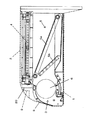
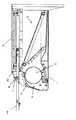
以下、図面に基づいて本発明の実施の形態を説明する。本実施形態においては、空気調節装置として冷暖房機能をメイン機能とするセパレート型空気調和機の室内機を用い、この室内機に本発明に係るフィルターを搭載した場合について説明する。図1は、空気調和機の室内機の外観斜視図であり、図2は、図1における室内機のキャビネットを外した状態のA−A断面図を示す。   Hereinafter, embodiments of the present invention will be described with reference to the drawings. In the present embodiment, a description will be given of a case where a separate air conditioner indoor unit having a cooling / heating function as a main function is used as an air conditioner and the filter according to the present invention is mounted on the indoor unit. FIG. 1 is an external perspective view of an indoor unit of an air conditioner, and FIG. 2 is a cross-sectional view taken along line AA in FIG. 1 with the cabinet of the indoor unit removed.

本実施形態では、送風ファン6が、室内熱交換器5よりも前方に位置しており、これにより、室内機のキャビネット1は高さが低く、その分、奥行きがある扁平な形状とされ、室内壁の上部天井近傍に設置可能とされている。   In the present embodiment, the blower fan 6 is positioned in front of the indoor heat exchanger 5, whereby the cabinet 1 of the indoor unit has a low height, and accordingly has a flat shape with a depth, It can be installed near the upper ceiling of the indoor wall.

キャビネット1の天面は、そのほぼ全面が吸込口2とされ、吸込口2の裏面側に本発明に係るフィルターとして集塵フィルター4が配されている。キャビネット1の前面には、その上部を除いて吹出口3が形成されている。吹出口3には、空気の流れの向きを上下方向に変えるルーバー9が揺動自在に取り付けられている。このルーバー9は、冷暖房気流の送風をOFFしたときは速やかに稼働し、図1に示すように、吹出口3を閉じた状態にする。すなわち、ルーバー9は、吹出口3を閉じる開閉パネルの役割も有している。   The almost entire surface of the top surface of the cabinet 1 is a suction port 2, and a dust collection filter 4 is disposed on the back side of the suction port 2 as a filter according to the present invention. A blower outlet 3 is formed on the front surface of the cabinet 1 except for its upper part. A louver 9 for changing the direction of the air flow in the vertical direction is swingably attached to the air outlet 3. The louver 9 operates quickly when the air-conditioning airflow is turned off, and closes the outlet 3 as shown in FIG. That is, the louver 9 also has a role of an open / close panel that closes the outlet 3.

吹出口3の上部には、メンテナンス時に集塵フィルター4を着脱自在に引出すための横長の引出口7,7が形成される(図10、図11参照)。各引出口7には、適宜、保護カバー8が開閉回動自在に設けられている。集塵フィルター4は、後述する枠体15,16と共に引出口7から引き出し可能となっている。   In the upper part of the air outlet 3, horizontally long outlets 7 and 7 for detachably pulling out the dust collecting filter 4 during maintenance are formed (see FIGS. 10 and 11). A protective cover 8 is appropriately provided at each outlet 7 so as to be openable and closable. The dust collecting filter 4 can be pulled out from the outlet 7 together with frames 15 and 16 described later.

キャビネット1の内部には、吸込口2から吹出口3に至る通風路が形成され、この通風路には吸込口2側を上流側として、集塵フィルター4、室内熱交換器5、送風ファン6がこの順に配置される。送風ファン6は、回転軸方向をキャビネットの左右方向とするクロスフローファンであって、吹出口3の近傍に配置される。室内熱交換器5は、吸込口2の下方であって、送風ファン6の後側に配置される。   Inside the cabinet 1, a ventilation path from the suction port 2 to the blowout port 3 is formed. In this ventilation path, the dust collection filter 4, the indoor heat exchanger 5, and the blower fan 6 are arranged with the suction port 2 side as the upstream side. Are arranged in this order. The blower fan 6 is a cross-flow fan whose rotation axis direction is the left-right direction of the cabinet, and is arranged in the vicinity of the blower outlet 3. The indoor heat exchanger 5 is disposed below the suction port 2 and on the rear side of the blower fan 6.

室内熱交換器5は、通風路の上流側に配置された第一熱交換器5aと、その下流側に配された第二熱交換器5bとを備え、両熱交換器が接続されて再熱除湿可能な構成となっている。   The indoor heat exchanger 5 includes a first heat exchanger 5a disposed on the upstream side of the ventilation path and a second heat exchanger 5b disposed on the downstream side thereof. It has a configuration capable of heat dehumidification.

第一熱交換器5aは、吸込口2の下方において、キャビネット天面の吸込口2と対向する程度に大きな一枚の平板状に形成されている。具体的には、第一熱交換器5aは、微細な通路を有する扁平な冷媒管を平行に多数配列され、その間にコルゲート状のフィンが配設されてなるアルミニウム製のパラレルフロー型の熱交換器から構成され、全体として板状でコンパクトな形状であっても熱交換効率が良好となっている。この第一熱交換器5aは、例えば、冷却除湿時に蒸発器として機能する。そして、第一熱交換器5aは、冷却除湿時に付着した水滴が吹出口3側に流れるのを防止するため、前方を上側にして前後方向で傾斜して配置されている。   The first heat exchanger 5a is formed in a single flat plate shape below the suction port 2 so as to face the suction port 2 on the top surface of the cabinet. Specifically, the first heat exchanger 5a is a parallel flow type heat exchange made of aluminum in which a large number of flat refrigerant tubes having fine passages are arranged in parallel and corrugated fins are arranged therebetween. Even if it is a plate-like and compact shape as a whole, the heat exchange efficiency is good. This 1st heat exchanger 5a functions as an evaporator at the time of cooling dehumidification, for example. And the 1st heat exchanger 5a is inclined and arrange | positioned in the front-back direction with the front facing up, in order to prevent the water droplet adhering at the time of cooling dehumidification flowing into the blower outlet 3 side.

一方、第二熱交換器5bは、平行に配列された多数の伝熱フィンを貫通する冷媒管が蛇行状に配列してなるフィンアンドチューブ型の熱交換器から構成されている。第二熱交換器5bは、第一熱交換器5aの前部下方位置で、前方を上側にして前後方向に傾斜して配置され、第一熱交換器5aで発生した水滴が吹出口3から室内側へ放出されるのを阻止できるようになっている。   On the other hand, the 2nd heat exchanger 5b is comprised from the fin and tube type heat exchanger with which the refrigerant | coolant tube which penetrates many heat-transfer fins arranged in parallel is arranged in the meandering form. The second heat exchanger 5b is disposed at a front lower position of the first heat exchanger 5a and inclined in the front-rear direction with the front facing upward, and water droplets generated in the first heat exchanger 5a are discharged from the blowout port 3. It can be prevented from being released indoors.

なお、第一熱交換器5aはパラレルフロー型の熱交換器とし、第二熱交換器5bはフィンアンドチューブ型の熱交換器としたが、これに限るものではない。また、室内熱交換器5は、複数の熱交換器から構成する以外に単体の熱交換器から構成してもよいことは勿論である。   The first heat exchanger 5a is a parallel flow type heat exchanger, and the second heat exchanger 5b is a fin-and-tube type heat exchanger, but is not limited thereto. Of course, the indoor heat exchanger 5 may be composed of a single heat exchanger in addition to a plurality of heat exchangers.

上記構成の室内機において空気調和運転を行なうと、送風ファン6が稼動して吸込口2から室内空気が吸い込まれ、その室内空気は集塵フィルター4を通過して室内熱交換器5と接触して熱交換され、空気調和された室内空気が吹出口3から室内に放出される。   When the air conditioning operation is performed in the indoor unit configured as described above, the blower fan 6 is activated and the indoor air is sucked from the suction port 2, and the indoor air passes through the dust collection filter 4 and comes into contact with the indoor heat exchanger 5. Then, heat-exchanged and air-conditioned indoor air is discharged into the room from the air outlet 3.

上述のように、キャビネット1を左右方向に幅広で、奥行きのある扁平な形状とすることにより、送風ファン6よりも後方のキャビネット1内の空間を室内熱交換器5の設置スペースとして活用することができ、室内熱交換器5の熱交換効率を高めることが可能となる。   As described above, the space in the cabinet 1 behind the blower fan 6 is utilized as the installation space for the indoor heat exchanger 5 by making the cabinet 1 wide in the left-right direction and flat with depth. Thus, the heat exchange efficiency of the indoor heat exchanger 5 can be increased.

上述のように、空気を吸い込む吸込口2と室内熱交換器5との間には、集塵フィルター4が介設される。集塵フィルター4は、平板状で長方形に形成された同形の第一フィルター10及び第二フィルター11の2枚から構成される。第一フィルター10及び第二フィルター11は、吸込口2の下流側で、吸込口2に対して並列に配置される。具体的には、各フィルター10,11の短手方向が天面の前後方向になるように(言い換えれば、各フィルター10,11の長手方向が天面の左右方向になるように)して吸込口2の下流側でほぼ水平な同一平面上に左右横並びで設置される。そして、本室内機には、第一フィルター10及び第二フィルター11を清掃するフィルター清掃装置20が設けられている。   As described above, the dust collection filter 4 is interposed between the air inlet 2 for sucking air and the indoor heat exchanger 5. The dust collection filter 4 is composed of two plates, a first filter 10 and a second filter 11 having the same shape and formed in a flat plate and a rectangle. The first filter 10 and the second filter 11 are arranged in parallel to the suction port 2 on the downstream side of the suction port 2. Specifically, suction is performed such that the short direction of each filter 10, 11 is the front-rear direction of the top surface (in other words, the longitudinal direction of each filter 10, 11 is the left-right direction of the top surface). They are installed side by side on the same plane that is substantially horizontal on the downstream side of the mouth 2. The indoor unit is provided with a filter cleaning device 20 for cleaning the first filter 10 and the second filter 11.

図7は、第一フィルター10の斜視図であり、図8に図7のB−B断面図を、図9に図7のC−C断面図をそれぞれ示す。なお、第二フィルター11は、第一フィルター10と形態が同じとされている。図7に示すように、両フィルター(第一フィルター10及び第二フィルター11)は、いずれもメッシュフィルターからなる矩形のフィルター部12と、そのフィルター部12の外周を囲むように支持する四角枠状の枠部13とを備えている。フィルター部12は、編み組織あるいは織り組織からなる合成樹脂製のフィルターの表裏面において、前記枠部13の内側で前後左右方向に差し渡された格子状の補強部14が設けられ、この補強部14によってフィルターが補強されている。   7 is a perspective view of the first filter 10. FIG. 8 is a cross-sectional view taken along line BB of FIG. 7, and FIG. 9 is a cross-sectional view taken along line CC of FIG. The second filter 11 has the same form as the first filter 10. As shown in FIG. 7, both filters (first filter 10 and second filter 11) are rectangular filter parts 12 each made of a mesh filter, and a rectangular frame shape that supports the outer periphery of the filter part 12. Frame portion 13. The filter portion 12 is provided with a lattice-like reinforcing portion 14 that is provided in the front and back, right and left directions inside the frame portion 13 on the front and back surfaces of a filter made of a synthetic resin having a knitted structure or a woven structure. The filter is reinforced by 14.

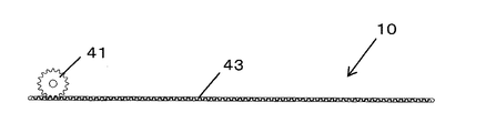
第一フィルター10及び第二フィルター11の前端縁及び後端縁には、第一フィルター10及び第二フィルター11を左右方向に移動搬送するために、後述するように駆動装置としての駆動ギア41に噛合可能な凹凸部43が左右方向にわたって形成されている。この凹凸部43は、図7及び図8に示すように、枠部の前後外側に形成されている。   In order to move and convey the first filter 10 and the second filter 11 in the left-right direction at the front edge and the rear edge of the first filter 10 and the second filter 11, as described later, a drive gear 41 as a drive device is provided. Engaging irregularities 43 are formed in the left-right direction. As shown in FIGS. 7 and 8, the uneven portion 43 is formed on the front and rear outside of the frame portion.

凹凸部43は、第一フィルター10及び第二フィルター11を表裏逆転させても使用可能なコルゲート形状に形成されている。すなわち、駆動ギア41と噛合する面に形成された凹凸部43の凹部の他面側に凸部が形成され、凸部の他面側に凹部が形成される。したがって、ひとつの凹凸部43を形成することで、表裏逆転させても駆動ギア41と噛合可能とされる。なお、第一フィルター10及び第二フィルター11は、少なくとも凹凸部43を除く他の部分の構造が表裏対称、かつ前後対称及び左右対称とされている。   The uneven portion 43 is formed in a corrugated shape that can be used even when the first filter 10 and the second filter 11 are reversed. That is, a convex portion is formed on the other surface side of the concave portion of the concave and convex portion 43 formed on the surface meshing with the drive gear 41, and a concave portion is formed on the other surface side of the convex portion. Therefore, by forming one concave and convex portion 43, it is possible to mesh with the drive gear 41 even if the front and back are reversed. In the first filter 10 and the second filter 11, the structure of at least the other parts excluding the concavo-convex part 43 is front-back symmetric, front-back symmetric, and left-right symmetric.

第一フィルター10又は第二フィルター11を表裏逆転させる場合、フィルターの左右方向中央を中心として左右を反対にするように逆転させるケースと、フィルターの前後方向中央を中心として前後を反対にするように逆転させるケースとが考えられる。   When the first filter 10 or the second filter 11 is reversed, the case where the filter is reversed so that the left and right are reversed with the center in the left and right direction of the filter as the center, and the front and back are reversed with the center in the front and rear direction of the filter as the center. It is possible to reverse the case.

したがって、凹凸部43の形成位置としては、フィルターの前後方向中央を中心として前後を反対にするように逆転させるケースのときでも、逆転の前後における凹凸部43の位置が同じになるようにすることが好ましい。この点、本実施形態においては、凹凸部43はフィルターの前後端縁に形成されているため、逆転の前後で凹凸部43は同じ位置となる。   Therefore, the position of the concave / convex portion 43 should be the same even before and after the reverse rotation, even in the case of reverse rotation so that the front / rear direction is reversed about the center in the front / rear direction of the filter. Is preferred. In this respect, in the present embodiment, since the uneven portion 43 is formed at the front and rear end edges of the filter, the uneven portion 43 is in the same position before and after the reverse rotation.

また、上記2ケースのうち、いずれか一方のケースにおいて、逆転の前後における凹凸部43の凹凸周期が同期するように凹凸部43を形成したとしても、他方のケースにおいては凹凸周期は1/2ピッチずれることになる。このように凹凸周期がずれた場合でも、駆動ギア41の歯部及び凹凸部43の凸部の頂部を滑らかな曲面で形成することにより、駆動ギア41と凹凸部43とをスムーズに噛合させることができる。これにより、左右方向に逆転させても前後方向に逆転させても、駆動ギア41と凹凸部43とをスムーズに噛合させることが可能となる。   Moreover, even if the uneven | corrugated part 43 is formed so that the uneven | corrugated period of the uneven | corrugated | grooved part 43 before and behind reversal may synchronize in any one of said 2 cases, an uneven | corrugated period is 1/2 in the other case. The pitch will shift. Even when the uneven period is shifted as described above, the drive gear 41 and the uneven part 43 are smoothly meshed by forming the tooth part of the drive gear 41 and the top part of the convex part of the uneven part 43 with a smooth curved surface. Can do. As a result, the drive gear 41 and the concavo-convex portion 43 can be smoothly engaged with each other regardless of whether they are reversed in the left-right direction or in the front-rear direction.

凹凸部43の高さは、図8に示すように、枠部13の厚み以下に設定されている。つまり、集塵フィルター4において、周囲の枠部13の厚みが最も厚く形成されている。ここで、枠部13及び補強部14の厚みは特に限定はないが、本実施形態においては、1.0mm〜1.5mm程度と比較的薄く形成され、さらに、枠部13および補強部14と、フィルター部12との厚みの差も少なく、両者の間の段差部(枠部13や補強部14の隅)の塵埃が取り残されない形状とされている。また、枠部13及び補強部14は同一の合成樹脂により一体的に形成されている。前記合成樹脂としては、メラミン樹脂やナイロン樹脂等の硬質樹脂が好ましく、これによって、反りや捩じれが少なく、厚みが薄くても剛性に優れ、凹凸部43の成形精度に優れたフィルターを得ることができる。特に、ナイロン樹脂を使用した場合には、滑性に優れ、よりスムーズな往復移動が可能となる。或いは、合成樹脂として、ABS樹脂やPS樹脂を用いてもよい。   The height of the uneven portion 43 is set to be equal to or less than the thickness of the frame portion 13 as shown in FIG. That is, in the dust collection filter 4, the surrounding frame portion 13 is formed to be the thickest. Here, although the thickness of the frame part 13 and the reinforcement part 14 is not particularly limited, in the present embodiment, the frame part 13 and the reinforcement part 14 are formed to be relatively thin, approximately 1.0 mm to 1.5 mm. The difference between the thickness of the filter portion 12 and the filter portion 12 is small, and the dust is not left behind in the stepped portion (the corners of the frame portion 13 and the reinforcing portion 14) between them. Further, the frame portion 13 and the reinforcing portion 14 are integrally formed of the same synthetic resin. As the synthetic resin, a hard resin such as a melamine resin or a nylon resin is preferable, and thereby, a filter having less warpage and twisting, excellent rigidity even when the thickness is small, and excellent molding accuracy of the uneven portion 43 can be obtained. it can. In particular, when nylon resin is used, it is excellent in lubricity and can be reciprocated more smoothly. Alternatively, ABS resin or PS resin may be used as the synthetic resin.

そして、第一フィルター10及び第二フィルター11は、前述のごとく、凹凸部43を除く他の部分の構造が表裏対称、かつ前後対称及び左右対称とされている。これにより、後述する除塵部21内をフィルター10及び11が通過する際に、両者の相対的な位置関係が表裏面で同じであることから、第一フィルター10又は第二フィルター11を表裏逆にしても除塵部21のシール性を保持することが可能となり、良好な除塵性能を維持することができる。なお、フィルター10及び11は、表裏逆転させた状態でも枠体15,16に収容可能となっている。   In the first filter 10 and the second filter 11, as described above, the structure of the other parts excluding the concavo-convex portion 43 is front-back symmetric, front-back symmetric, and left-right symmetric. As a result, when the filters 10 and 11 pass through the dust removing unit 21 described later, the relative positional relationship between the two is the same on the front and back surfaces, so the first filter 10 or the second filter 11 is turned upside down. However, it becomes possible to maintain the sealing performance of the dust removing portion 21 and maintain good dust removal performance. The filters 10 and 11 can be accommodated in the frame bodies 15 and 16 even when the front and back are reversed.

フィルター清掃装置20は、図3及び図4に示すように、集塵フィルター4に付着した塵埃を除去する除塵部21を備えている。除塵部21は、細長いボックス状に形成され、長さ方向をキャビネット1の前後方向に合わせるようにしてキャビネット1の中央部に設置される。   As shown in FIGS. 3 and 4, the filter cleaning device 20 includes a dust removing unit 21 that removes dust attached to the dust collection filter 4. The dust removal unit 21 is formed in a long and narrow box shape, and is installed in the center of the cabinet 1 so that the length direction matches the front-rear direction of the cabinet 1.

除塵部21の長さ方向一端側には吸気口22が形成され、他端側には空気を吸引する吸引装置23が接続されている。これにより、除塵部21の長さ方向一端側から他端側に向けて空気流を発生させることが可能となる。除塵部21内部には、両フィルター10及び11に付着した塵埃を掻き取る一対の清掃ブラシ28が設置されている。   An intake port 22 is formed on one end side in the length direction of the dust removing portion 21, and a suction device 23 for sucking air is connected to the other end side. Thereby, it becomes possible to generate an air flow from one end side in the length direction of the dust removing portion 21 toward the other end side. A pair of cleaning brushes 28 for scraping off dust adhering to both the filters 10 and 11 are installed inside the dust removing portion 21.

吸引装置23は、室内熱交換器5の設置の妨げにならないよう、図4に示すように、キャビネット1内の左右方向一端部に設置され、吸引装置23と除塵部21との間は、ダクト24によって接続されている。吸引装置23によって集塵フィルター4から除去された塵埃は、集塵ボックス25に溜められる。   As shown in FIG. 4, the suction device 23 is installed at one end in the left-right direction in the cabinet 1 so as not to hinder the installation of the indoor heat exchanger 5, and a duct is provided between the suction device 23 and the dust removal unit 21. 24 is connected. The dust removed from the dust collection filter 4 by the suction device 23 is stored in the dust collection box 25.

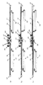
集塵フィルター4を構成する第一フィルター10及び第二フィルター11は、図3のように、除塵部21を挟んでその両側に配される。そして、図5(a)に示すように、第一フィルター10及び第二フィルター11に平行で、かつ除塵部21内を通過する第一フィルター10及び第二フィルター11の搬送ラインLが設定され、この搬送ラインLが除塵部21の両側面と交わる部分に、第一フィルター10及び第二フィルター11を除塵部内部に案内するための共通の開口26,26が形成される。   As shown in FIG. 3, the first filter 10 and the second filter 11 constituting the dust collection filter 4 are arranged on both sides of the dust removal unit 21. And as shown to Fig.5 (a), the conveyance line L of the 1st filter 10 and the 2nd filter 11 which is parallel to the 1st filter 10 and the 2nd filter 11, and passes the inside of the dust removal part 21 is set, Common openings 26 and 26 for guiding the first filter 10 and the second filter 11 to the inside of the dust removing portion are formed at portions where the conveying line L intersects both side surfaces of the dust removing portion 21.

開口26と、第一フィルター10及び第二フィルター11との接触面にはゴム等からなる弾性部材27が配置されており、集塵フィルター清掃時において、吸引装置23を稼働したときに、開口26の隙間を塞いで主に吸気口22から空気を取り入れるようにし、除塵部21の長さ方向一端側から他端側に向かう空気流を効率よく発生させるようにしている。   An elastic member 27 made of rubber or the like is disposed on the contact surface between the opening 26 and the first filter 10 and the second filter 11. When the suction device 23 is operated when cleaning the dust collecting filter, the opening 26 is provided. In order to efficiently generate an air flow from one end side in the length direction of the dust removing portion 21 to the other end side, the air is mainly taken in from the intake port 22.

除塵部21の内部には一対の清掃ブラシ28、28が設置されている。清掃ブラシ28は、円筒状の本体と、本体の周囲に設けられた植毛部とを備えており、本体が回転することにより、植毛部でフィルター面に付着した塵埃を掻き上げる構成とされている。除塵部21は、長さ方向の中心線が直線状になるように形成されており、清掃ブラシ28,28は、除塵部21の長さ方向に平行で、かつ、互いに対向するように配置されている。そして、清掃ブラシ28,28は、第一フィルター10及び第二フィルター11が、清掃ブラシ28,28の間を通過するように配される。   A pair of cleaning brushes 28 and 28 are installed inside the dust removing portion 21. The cleaning brush 28 includes a cylindrical main body and a flocked portion provided around the main body, and the main body rotates to scrape dust adhering to the filter surface at the flocked portion. . The dust removing portion 21 is formed such that the center line in the length direction is linear, and the cleaning brushes 28 and 28 are arranged in parallel to the length direction of the dust removing portion 21 and facing each other. ing. The cleaning brushes 28 and 28 are arranged so that the first filter 10 and the second filter 11 pass between the cleaning brushes 28 and 28.

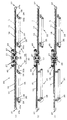
さらに、フィルター清掃装置20は、図5及び図6に示すように、第一フィルター10及び第二フィルター11を搬送ラインLまで平行移動させる平行移動機構30と、搬送ラインL上にセットされた第一フィルター10及び第二フィルター11のうちの一方のフィルターを、除塵部21内を通過して他方のフィルター側まで往復移動させるフィルター搬送機構40とを備えている。   Further, as shown in FIGS. 5 and 6, the filter cleaning device 20 includes a parallel movement mechanism 30 that translates the first filter 10 and the second filter 11 to the conveyance line L, and a first set on the conveyance line L. A filter transport mechanism 40 that reciprocally moves one of the one filter 10 and the second filter 11 through the dust removing portion 21 to the other filter side is provided.

第一フィルター10及び第二フィルター11は、図3のごとく、それぞれ第一枠体15及び第二枠体16に収容されている。第一枠体15及び第二枠体16はそれぞれ、上枠部15a,16aと下枠部15b,16bとが一定の隙間をあけて対向し、その隙間に第一フィルター10又は第二フィルター11を挿入可能な扁平箱型形状とされている。枠体15,16のそれぞれの前面には、第一フィルター10及び第二フィルター11をそれぞれ挿入するための挿入口18が形成されている。また、枠体15,16が除塵部21を挟んで互いに対向する面には、第一フィルター10又は第二フィルター11が搬送ラインLを移動するための出入口として側口17が形成されている(図5参照)。   The first filter 10 and the second filter 11 are accommodated in the first frame 15 and the second frame 16, respectively, as shown in FIG. In the first frame 15 and the second frame 16, the upper frame portions 15a and 16a and the lower frame portions 15b and 16b face each other with a certain gap, and the first filter 10 or the second filter 11 is opposed to the gap. It is a flat box shape that can be inserted. An insertion port 18 for inserting the first filter 10 and the second filter 11 is formed on the front surface of each of the frames 15 and 16. Moreover, the side port 17 is formed in the surface where the frame bodies 15 and 16 mutually oppose on both sides of the dust removal part 21 as an entrance / exit for the 1st filter 10 or the 2nd filter 11 to move the conveyance line L ( (See FIG. 5).

上枠部15a,16a及び下枠部15b,16bには、周縁部を除いて格子状に区画された開口部19が形成されており、この開口部19により、第一フィルター10及び第二フィルター11のそれぞれにおける空気の流通が確保されている。枠体15,16は、一体成形したものを用いてもよいし、別部材として形成した上枠部15a,16aと下枠部15b,16bとを組み立てるようにしてもよい。また、枠体15及び16の前端部中央には、図3に示すように、第一フィルター10及び第二フィルター11の前端部を一部露出させるための切込部48が形成されている。これにより、枠体15,16をキャビネット1の外部に突出させた状態で、切込部48において露出する第一フィルター10及び第二フィルター11を摘んで容易に引き出すことできる。   The upper frame portions 15a and 16a and the lower frame portions 15b and 16b are formed with openings 19 that are partitioned in a lattice shape except for the peripheral edge portions. The air circulation in each of 11 is ensured. The frames 15 and 16 may be integrally formed, or the upper frame portions 15a and 16a and the lower frame portions 15b and 16b formed as separate members may be assembled. Further, as shown in FIG. 3, a notch 48 is formed in the center of the front end of each of the frames 15 and 16 for exposing part of the front end of the first filter 10 and the second filter 11. Accordingly, the first filter 10 and the second filter 11 exposed at the cut portion 48 can be easily picked and pulled out with the frame bodies 15 and 16 projecting outside the cabinet 1.

第一フィルター10及び第二フィルター11は、図5及び図6に示すように、第一枠体15又は第二枠体16ごと平行移動機構30によって搬送ラインLまで移動する。上記枠体15及び16は、空気調和機運転時(例えば、暖房運転時や冷房運転時)には、ガイド37に載置され、この状態で、吸込口2から吸い込まれた空気中の塵埃が第一フィルター10及び第二フィルター11によって除去される。   As shown in FIGS. 5 and 6, the first filter 10 and the second filter 11 are moved to the transport line L by the parallel moving mechanism 30 together with the first frame 15 or the second frame 16. The frame bodies 15 and 16 are placed on the guide 37 during the air conditioner operation (for example, during the heating operation or the cooling operation), and in this state, dust in the air sucked from the air inlet 2 is removed. It is removed by the first filter 10 and the second filter 11.

第一枠体15及び第二枠体16は、2組のガイド37,37によってキャビネット前方にスライド可能に支持される。第一枠体15は、図5において、除塵部21の左側に配置された左側ガイド37によって支持される。第二枠体16は、同図において、除塵部21の右側に配置された右側ガイド37によって支持される。   The first frame body 15 and the second frame body 16 are supported by two sets of guides 37 and 37 so as to be slidable forward of the cabinet. The first frame 15 is supported by a left guide 37 disposed on the left side of the dust removing unit 21 in FIG. The second frame body 16 is supported by a right guide 37 disposed on the right side of the dust removing portion 21 in FIG.

各ガイド37は、除塵部21の長さ方向に沿って延びる断面L字形の一対のレール37a,37bから構成される。レール37a,37bは、左右方向に間隔をおいて配置される。レール37aは、図5において、左右方向で中央部(除塵部21)に配置され、レール37bは、左右方向で外側(キャビネット1の側面内側)に配置され、レール37a及び37bによって枠体15及び16の左右両端部が支持される。   Each guide 37 includes a pair of rails 37 a and 37 b having an L-shaped cross section extending along the length direction of the dust removing portion 21. The rails 37a and 37b are arranged at intervals in the left-right direction. In FIG. 5, the rail 37 a is disposed at the center portion (dust removing portion 21) in the left-right direction, and the rail 37 b is disposed on the outer side (inside the side surface of the cabinet 1) in the left-right direction. The left and right ends of 16 are supported.

さらに、前述のごとく、キャビネット1の前面のうち、ルーバ9の後方上部で、かつ、ガイド37上に保持された第一フィルター10及び第二フィルター11の先方に、第一フィルター10及び第二フィルター11をそれぞれ引き出すための引出口7,7が形成される。各引出口7には、上下方向に開閉可能な保護カバー8が設けられる(図1及び図2参照)。   Further, as described above, the first filter 10 and the second filter on the front side of the cabinet 1 at the rear upper part of the louver 9 and ahead of the first filter 10 and the second filter 11 held on the guide 37. The outlets 7 and 7 for pulling out 11 respectively are formed. Each outlet 7 is provided with a protective cover 8 that can be opened and closed in the vertical direction (see FIGS. 1 and 2).

第一フィルター10及び第二フィルター11のメンテナンスや交換等の際には、保護カバー8の下部を手で引き上げて開放し、図10に示すように、第一枠体15及び第二枠体16をガイド37に沿って前方に引き出す。これにより、枠体15,16は、前後方向長さの約1/2が引き出され、送風ファン6を越えてキャビネット1の前方に突出する。   When maintenance or replacement of the first filter 10 and the second filter 11 is performed, the lower part of the protective cover 8 is manually lifted and opened, and the first frame 15 and the second frame 16 are opened as shown in FIG. Is pulled forward along the guide 37. As a result, the frame bodies 15 and 16 are drawn out about a half of the length in the front-rear direction, and project beyond the blower fan 6 to the front of the cabinet 1.

なお、枠体15及び16を前方に引き出す際には、ラック−ピニオン等の公知の機構を採用することにより、自動的に行うようにしてもよい。さらに、その状態で、図11に示すように、両枠体15及び16内から第一フィルター10及び第二フィルター11を抜き出すことにより、容易かつスムーズに両フィルター10及び11を取り出すことが可能となる。   In addition, when pulling out the frame bodies 15 and 16 forward, you may make it perform automatically by employ | adopting well-known mechanisms, such as a rack-pinion. Further, in this state, as shown in FIG. 11, by extracting the first filter 10 and the second filter 11 from both the frame bodies 15 and 16, both the filters 10 and 11 can be easily and smoothly taken out. Become.

逆に、第一フィルター10及び第二フィルター11をキャビネット1内にセットするときは、キャビネット1の前方に突出した第一枠体15及び第二枠体16の挿入口18から、第一フィルター10及び第二フィルター11を挿入して各枠体内に収容に収容する。このとき、第一フィルター10及び第二フィルター11の縦横だけを確認すればよく、表裏や前後方向をチェックする必要がない。さらに、フィルター10及び11の状況を目視によって確認しながら枠体内に挿入することが可能となるため、第一フィルター10及び第二フィルター11をスムーズに各枠体15,16内に収容することができる。第一フィルター10及び第二フィルター11を各枠体15,16内に収容した後は、各枠体15,16をスライドさせてキャビネット1内に収容すればよい。   Conversely, when the first filter 10 and the second filter 11 are set in the cabinet 1, the first filter 10 is inserted from the insertion opening 18 of the first frame body 15 and the second frame body 16 protruding forward of the cabinet 1. And the 2nd filter 11 is inserted and accommodated in accommodation in each frame. At this time, it is only necessary to check the vertical and horizontal directions of the first filter 10 and the second filter 11, and it is not necessary to check the front and back sides and the front-rear direction. Further, since it is possible to insert the filter 10 and 11 into the frame while visually confirming the state of the filter 10, the first filter 10 and the second filter 11 can be smoothly accommodated in the respective frames 15 and 16. it can. After the first filter 10 and the second filter 11 are accommodated in the frames 15 and 16, the frame bodies 15 and 16 may be slid and accommodated in the cabinet 1.

平行移動機構30は、第一リフト機構31及び第二リフト機構32から構成され、それぞれガイド37に載置された状態の第一枠体15及び第二枠体16の下方に設置され、第一フィルター10及び第二フィルター11を枠体ごと別個に下方から搬送ラインLまで押し上げる構成とされている。   The parallel movement mechanism 30 includes a first lift mechanism 31 and a second lift mechanism 32, and is installed below the first frame body 15 and the second frame body 16 placed on the guide 37, respectively. The filter 10 and the second filter 11 are separately pushed up from the lower side to the conveying line L for each frame.

具体的に、第一リフト機構31及び第二リフト機構32は、平行に配置された2本の駆動シャフト33a及び従動シャフト33bと、駆動シャフト33a及び従動シャフト33bそれぞれの両端部に取り付けられたカム34,34と、駆動シャフト33aを回転させるモータ35と、駆動シャフト33aにリンクして従動シャフト33bを回転させる平行リンク機構36とを備えている。   Specifically, the first lift mechanism 31 and the second lift mechanism 32 include two drive shafts 33a and a driven shaft 33b arranged in parallel, and cams attached to both ends of the drive shaft 33a and the driven shaft 33b. 34, 34, a motor 35 that rotates the drive shaft 33a, and a parallel link mechanism 36 that links the drive shaft 33a and rotates the driven shaft 33b.

第一リフト機構31及び第二リフト機構32は、上述のごとく、それぞれ4つのカム34を備えており、モータ35によってこれらのカム34が同期して回転することで、枠体15,16が上下に平行移動可能とされる。具体的に、カム34(の最大径部分)が横向きのときは枠体15,16に接触せず、カム34が縦向きのときは、枠体15,16をガイド37から持ち上げて搬送ラインLまで移動させる。   As described above, each of the first lift mechanism 31 and the second lift mechanism 32 includes four cams 34. When these cams 34 are rotated in synchronization by a motor 35, the frame bodies 15 and 16 are moved up and down. Can be moved in parallel. Specifically, when the cam 34 (the maximum diameter portion thereof) is in the horizontal direction, it does not come into contact with the frames 15 and 16, and when the cam 34 is in the vertical direction, the frame bodies 15 and 16 are lifted from the guide 37 and are conveyed. To move.

なお、各カム34(の最大径部分)の先端には、ローラ38が回転自在に取り付けられている。したがって、カム34の回転に伴って、カム34と枠体15,16との間に不要な摩擦を生じることがなく、枠体15,16ごと第一フィルター10又は第二フィルター11をスムーズに上下に平行移動させることができる。   A roller 38 is rotatably attached to the tip of each cam 34 (the maximum diameter portion). Accordingly, unnecessary friction is not generated between the cam 34 and the frame bodies 15 and 16 as the cam 34 rotates, and the first filter 10 or the second filter 11 is smoothly moved up and down together with the frame bodies 15 and 16. Can be translated.

フィルター搬送機構40は、搬送ラインLを挟んで平行移動機構30とは反対側、すなわち、搬送ラインLの上方で、かつ除塵部21の両側に一組ずつ設置される。各フィルター搬送機構40は、一対の駆動ギア41,41から構成される。一対の駆動ギア41,41は、回転軸42に対し、間隔をあけて取り付けられている。回転軸42は、除塵部21の近傍で除塵部21の長さ方向に沿って設置され、その一端に駆動源としてモータ44が接続され、後述する制御部によりモータ44の駆動が制御される。   A pair of filter transport mechanisms 40 are installed on the opposite side of the parallel movement mechanism 30 across the transport line L, that is, above the transport line L and on both sides of the dust removing unit 21. Each filter transport mechanism 40 includes a pair of drive gears 41 and 41. The pair of drive gears 41 and 41 are attached to the rotating shaft 42 with a space therebetween. The rotating shaft 42 is installed in the vicinity of the dust removing unit 21 along the length direction of the dust removing unit 21. A motor 44 is connected to one end of the rotating shaft 42 as a drive source, and the driving of the motor 44 is controlled by a control unit described later.

図7に示すように、一対の駆動ギア41,41の間隔は、第一フィルター10の前端縁10aから後端縁10bまでの距離Xと同じとされる。第一フィルター10の前端縁10a及び後端縁10bには、駆動ギア41と噛合可能な凹凸部43がそれぞれ形成されている。なお、第二フィルター11の構成は、第一フィルター10と同じとされている。   As shown in FIG. 7, the distance between the pair of drive gears 41 and 41 is the same as the distance X from the front end edge 10 a to the rear end edge 10 b of the first filter 10. On the front end edge 10 a and the rear end edge 10 b of the first filter 10, an uneven portion 43 that can mesh with the drive gear 41 is formed. The configuration of the second filter 11 is the same as that of the first filter 10.

第一フィルター10及び第二フィルター11のうちの一方が平行移動機構30によって搬送ラインL上まで移動したときに、一対の駆動ギア41,41と凹凸部43とが係合し、駆動ギア41,41が回転することにより、一方のフィルターが他方のフィルター側に向かって搬送される。   When one of the first filter 10 and the second filter 11 moves to the conveyance line L by the parallel movement mechanism 30, the pair of drive gears 41 and 41 and the concavo-convex portion 43 are engaged, and the drive gear 41, By rotating 41, one filter is conveyed toward the other filter side.

なお、図5、図6に示すように、枠体15,16の駆動ギア41に対応する部分は切り欠いて噛合穴49が形成され、駆動ギア41と凹凸部43とが直接係合可能とされている。また、第一枠体15及び第二枠体16のそれぞれにおいて、除塵部21に対向する側面には、前述のごとく、側口17が形成され、この側口17を出入口として第一フィルター10又は第二フィルター11が搬送ラインL上を左右方向に移動可能とされている。   As shown in FIGS. 5 and 6, the portions corresponding to the drive gear 41 of the frames 15 and 16 are notched to form a meshing hole 49 so that the drive gear 41 and the concavo-convex portion 43 can be directly engaged. Has been. Further, in each of the first frame body 15 and the second frame body 16, as described above, the side port 17 is formed on the side surface facing the dust removing portion 21, and the first filter 10 or The second filter 11 is movable in the left-right direction on the transport line L.

第一フィルター10又は第二フィルター11が搬送ラインLを搬送されるときは、フィルター搬送機構40は、一方のフィルター側に設置された組のみならず他方のフィルター側に設置された組も駆動する。これにより、フィルター全体を除塵部21内に通過させることが可能となる。   When the first filter 10 or the second filter 11 is transported along the transport line L, the filter transport mechanism 40 drives not only the group installed on one filter side but also the group installed on the other filter side. . As a result, the entire filter can be passed through the dust removing unit 21.

上記構成において、空気調和機の運転を開始すると、フィルター清掃装置20は、図5(a)に示すように、第一フィルター10及び第二フィルター11がガイド37に載置された状態で、キャビネット1の吸込口2から空気が吸い込まれ、第一フィルター10及び第二フィルター11の表面に塵埃が付着する。   In the above configuration, when the operation of the air conditioner is started, the filter cleaning device 20 is configured so that the cabinet with the first filter 10 and the second filter 11 placed on the guide 37 as shown in FIG. Air is sucked in from the first suction port 2, and dust adheres to the surfaces of the first filter 10 and the second filter 11.

キャビネット1内には、入力回路、CPU、メモリ、出力回路を備えた制御部が設けられており、例えば、空気調和機の運転時間が所定時間に達したと判断した場合や、光センサ等の検出結果に基づいて第一フィルター10及び第二フィルター11の表面が汚れていると判断した場合に、吸引装置23、平行移動機構30、フィルター搬送機構40等の稼働を制御して集塵フィルターの清掃が行われる。   In the cabinet 1, a control unit including an input circuit, a CPU, a memory, and an output circuit is provided. For example, when it is determined that the operation time of the air conditioner has reached a predetermined time, an optical sensor, etc. When it is determined that the surfaces of the first filter 10 and the second filter 11 are dirty based on the detection result, the operation of the suction device 23, the parallel movement mechanism 30, the filter transport mechanism 40, etc. is controlled to control the dust collection filter. Cleaning is performed.

集塵フィルター清掃時には、制御部は、先ず、図5(b)に示すように、第一リフト機構31を稼働させ、第一フィルター10を第一枠体15ごとガイド37から持ち上げ、搬送ラインLまで上昇(平行移動)させ、フィルター搬送機構40と凹凸部43とを係合させる。その後、2組のフィルター搬送機構40,40を稼働させ、図5(c)のように、第一フィルター10を第二フィルター11側に向けて搬送する。それと同時に、吸引装置23を稼働させ、除塵部21内に空気流を発生させるとともに、除塵部21内部に設置された清掃ブラシ28を回転させる。これにより、除塵部21内に導入された第一フィルター10に付着した塵埃を掻き上げ浮き上がらせ、空気流によって塵埃を吹き飛ばして除塵する。   When cleaning the dust collection filter, the control unit first operates the first lift mechanism 31 as shown in FIG. 5B to lift the first filter 10 together with the first frame 15 from the guide 37, The filter transport mechanism 40 and the concavo-convex portion 43 are engaged with each other. Thereafter, the two sets of filter transport mechanisms 40 and 40 are operated, and the first filter 10 is transported toward the second filter 11 as shown in FIG. At the same time, the suction device 23 is operated to generate an air flow in the dust removing unit 21 and to rotate the cleaning brush 28 installed in the dust removing unit 21. Thereby, the dust adhering to the first filter 10 introduced into the dust removing unit 21 is lifted and lifted, and dust is blown off by the air flow to remove the dust.

第一フィルター10は、第二枠体16の上方に設置されたフィルター搬送機構40によって第二枠体16を搬送ラインLのガイドとして利用している。すなわち、第二枠体16の上枠部16aの上面を搬送ラインLのガイドとして利用することで、第一フィルター10は、その上面をスライド移動して第二フィルター11と重合する位置(折返し位置)まで搬送される。制御部は、マイクロスイッチや、フィルター搬送機構40の合計回転数等から、第一フィルター10が折返し位置に到達したと判断したときに、フィルター搬送機構40,40を反対向きに回転させ、第一フィルター10を第一枠体15内に収容し終えた時点で、フィルター搬送機構40,40を停止させる。   The first filter 10 uses the second frame 16 as a guide for the transport line L by the filter transport mechanism 40 installed above the second frame 16. That is, by using the upper surface of the upper frame portion 16a of the second frame body 16 as a guide for the transport line L, the first filter 10 slides on the upper surface and overlaps with the second filter 11 (folding position). ). When the control unit determines that the first filter 10 has reached the folding position based on the microswitch, the total number of rotations of the filter transport mechanism 40, and the like, the control section rotates the filter transport mechanisms 40, 40 in the opposite direction, When the filter 10 has been accommodated in the first frame 15, the filter transport mechanisms 40, 40 are stopped.

その後、制御部は、第一リフト機構31を下降させ、第一フィルター10を第一枠体15ごとガイド37に載置し、カム34が第一枠体15から離れた時点で第一リフト機構31を停止させる。以上の動作を第二フィルター11についても同様に行い(図6(a)〜図6(c)参照)、集塵フィルター清掃を終了する。   Thereafter, the control unit lowers the first lift mechanism 31, places the first filter 10 together with the first frame 15 on the guide 37, and the first lift mechanism when the cam 34 is separated from the first frame 15. 31 is stopped. The above operation is similarly performed for the second filter 11 (see FIGS. 6A to 6C), and the dust collection filter cleaning is finished.

なお、本発明は、上記実施形態に限定されるものではなく、本発明の範囲内で上記実施形態に多くの修正及び変更を加え得ることは勿論である。例えば、本実施の形態では、集塵フィルター使用時(冷房運転時や暖房運転時などの空気調和機運転時)には、第一フィルター10及び第二フィルター11をガイド37に載置(同一平面上に配置)し、フィルター清掃時に両フィルター10及び11を交互に搬送ラインLまで平行移動させているが、これに限らず、例えば、集塵フィルター使用時に第一フィルター10及び第二フィルター11の両方を搬送ラインL上に配置(同一平面上に配置)し、集塵フィルター清掃時に、一方のフィルターを下降させてガイド37上に載置して搬送ラインLから外れた位置で待機させるようにすることも可能である。   In addition, this invention is not limited to the said embodiment, Of course, many corrections and changes can be added to the said embodiment within the scope of the present invention. For example, in the present embodiment, the first filter 10 and the second filter 11 are placed on the guide 37 (on the same plane) when the dust collection filter is used (when the air conditioner is in operation such as cooling or heating). However, the present invention is not limited to this. For example, when the dust collection filter is used, the first filter 10 and the second filter 11 Both are arranged on the conveying line L (arranged on the same plane), and when cleaning the dust collecting filter, one filter is lowered and placed on the guide 37 to stand by at a position off the conveying line L. It is also possible to do.

あるいは、集塵フィルター使用時に第一フィルター10と第二フィルター11のいずれか一方を搬送ラインL上に配置し、他方をフィルターをガイド37上に載置しておいてもよい。この場合、第一フィルター10と第二フィルター11とは、集塵フィルター使用時には同一平面上に設置されない。よって、集塵フィルター清掃時には、搬送ラインL上に配置されたフィルターから清掃を行い、つぎに、ガイド37上に載置されたもう一方のフィルターを搬送ラインLに配置して清掃させることも可能である。また、このとき、清掃前の状態に戻さず、後から清掃されたフィルターを搬送ラインL上に配置する(言い換えれば、清掃前に搬送ラインL上にあったフィルターとガイド37上にあったフィルターとが、清掃後に、配置箇所が入れ替わっている)ようにしてもよい。このようにすれば、フィルターの平行移動の回数を減らすことができるので、清掃時間の短縮や、省エネとすることができる。   Alternatively, when using the dust collection filter, either the first filter 10 or the second filter 11 may be arranged on the transport line L, and the other may be placed on the guide 37. In this case, the first filter 10 and the second filter 11 are not installed on the same plane when the dust collection filter is used. Therefore, when cleaning the dust collecting filter, it is possible to clean from the filter disposed on the transport line L, and then to clean the other filter placed on the guide 37 by placing it on the transport line L. It is. At this time, the filter that has been cleaned later is placed on the transport line L without returning to the state before cleaning (in other words, the filter that was on the transport line L before cleaning and the filter that was on the guide 37). However, the arrangement location may be changed after cleaning). In this way, the number of parallel movements of the filter can be reduced, so that the cleaning time can be shortened and energy can be saved.

本実施形態では、集塵フィルター4をキャビネット1の左右方向に移動させる空気調節装置にて説明したが、集塵フィルター4をキャビネット1の上下方向(前後方向)に移動させる空気調節装置であってもよい。また、集塵フィルター形状は、長方形状でなく、正方形状であってもよい。   In the present embodiment, the air conditioner that moves the dust collection filter 4 in the left-right direction of the cabinet 1 has been described. However, the air conditioner apparatus moves the dust collection filter 4 in the vertical direction (front-rear direction) of the cabinet 1. Also good. Further, the shape of the dust collecting filter may be a square shape instead of a rectangular shape.

また、本実施の形態では、凹凸部43はフィルターの前後端縁に形成されているが、必ずしもこの位置である必要はなく、フィルターの前後方向中央を中心として前後を反対にするように逆転させるケースのときに、逆転の前後における凹凸部43の位置が同じになるように位置に形成すればよい。なお、本実施形態よりも使用性が少し劣るが、フィルターの左右方向中央を中心として左右を反対にするようにフィルターの表裏を逆転させるケースと、フィルターの前後方向中央を中心として前後を反対にするようにフィルターの表裏を逆転させるケースと、のいずれか一方のケースにおいてのみ、逆転の前後における凹凸部43の位置が同じになるようにしてもよい。   Further, in the present embodiment, the uneven portion 43 is formed at the front and rear end edges of the filter, but it is not always necessary to be at this position, and is reversed so that the front and rear are reversed in the center in the front and rear direction of the filter. What is necessary is just to form in the position so that the position of the uneven | corrugated | grooved part 43 before and after reverse rotation may become the same at the time of a case. In addition, although the usability is slightly inferior to the present embodiment, the case where the front and back of the filter are reversed so that the left and right sides are reversed about the center in the left and right direction of the filter, and the front and back are reversed about the center in the front and rear direction of the filter Thus, the position of the uneven portion 43 before and after the reverse rotation may be the same only in either one of the cases where the front and back of the filter are reversed.

本発明の実施形態を示す空気調和機の室内機斜視図Indoor unit perspective view of an air conditioner showing an embodiment of the present invention 図1における室内機のキャビネットを外した状態のA-A断面図AA sectional view of the indoor unit in FIG. 1 with the cabinet removed フィルター清掃装置の上方斜視図Upper perspective view of filter cleaning device フィルター清掃装置の下方斜視図Lower perspective view of filter cleaning device フィルター清掃装置の正面図で、(a)は集塵フィルター使用時の状態を、(b)は第一フィルターを搬送ラインに移動させた状態を、(c)は第一フィルター往復移動時の状態を、それぞれ示す。It is a front view of a filter cleaning device, (a) is a state when using a dust collection filter, (b) is a state where the first filter is moved to the transport line, (c) is a state when the first filter is reciprocating. Are shown respectively. フィルター清掃装置の正面図で、(a)は集塵フィルター使用時の状態を、(b)は第二フィルターを搬送ラインに移動させた状態を、(c)は第二フィルター往復移動時の状態を、それぞれ示す。It is a front view of a filter cleaning device, (a) is a state when using a dust collection filter, (b) is a state where the second filter is moved to the transport line, (c) is a state when the second filter is reciprocating. Are shown respectively. 第一フィルターの斜視図Perspective view of the first filter 図7のB-B断面図BB sectional view of FIG. 図7のC-C断面図CC sectional view of FIG. 図2において枠体を引き出した状態を示す断面図Sectional drawing which shows the state which pulled out the frame in FIG. 図10において枠体からフィルターを引き出した状態を示す断面図Sectional drawing which shows the state which pulled out the filter from the frame in FIG.

符号の説明Explanation of symbols

1 キャビネット
2 吸込口
3 吹出口
4 集塵フィルター
5 室内熱交換器
6 送風ファン
7 引出口
8 保護カバー
9 ルーバー
10 第一フィルター
11 第二フィルター
12 フィルター部
13 枠部
14 補強部
15 第一枠体
16 第二枠体
17 側口
18 挿入口
20 フィルター清掃装置
21 除塵部
22 吸気口
23 吸引装置
24 ダクト
25 集塵ボックス
26 開口
27 弾性部材
28 清掃ブラシ
30 平行移動機構
31 第一リフト機構
32 第二リフト機構
33 シャフト
34 カム
35 モータ
36 リンク機構
37 ガイド
40 フィルター搬送機構
41 駆動ギア
42 回転軸
43 凹凸部
44 モータ
49 噛合穴
DESCRIPTION OF SYMBOLS 1 Cabinet 2 Inlet 3 Outlet 4 Dust collection filter 5 Indoor heat exchanger 6 Blower fan 7 Outlet 8 Protective cover 9 Louver 10 First filter 11 Second filter 12 Filter part 13 Frame part 14 Reinforcement part 15 First frame body 16 Second Frame 17 Side Port 18 Insert Port 20 Filter Cleaning Device 21 Dust Removal Unit 22 Air Intake Port 23 Suction Device 24 Duct 25 Dust Collection Box 26 Opening 27 Elastic Member 28 Cleaning Brush 30 Parallel Movement Mechanism 31 First Lift Mechanism 32 Second Lift mechanism 33 Shaft 34 Cam 35 Motor 36 Link mechanism 37 Guide 40 Filter transport mechanism 41 Drive gear 42 Rotating shaft 43 Concavity and convexity 44 Motor 49 Mating hole

Claims (5)

フィルターを移動させる駆動装置に噛合するための凹凸部がフィルター移動方向に沿って形成され、前記凹凸部は、フィルターの一面側に形成された凹部の他面側に凸部が形成され、フィルターの一面側に形成された凸部の他面側に凹部が形成され、フィルターの一面側と他面側とが同一凹凸形状とされたことを特徴とするフィルター。 An uneven portion for meshing with a drive device for moving the filter is formed along the filter moving direction, and the uneven portion is formed with a convex portion on the other surface side of the concave portion formed on the one surface side of the filter. A filter, wherein a concave portion is formed on the other surface side of the convex portion formed on the one surface side, and the one surface side and the other surface side of the filter have the same uneven shape. 前記フィルターが、フィルター部と、該フィルター部の外周を囲む枠部とを備え、前記凹凸部は前記枠部の一部に形成され、凹凸部の高さが枠部の厚み以下に設定されたことを特徴とする請求項1記載のフィルター。 The filter includes a filter part and a frame part surrounding the outer periphery of the filter part, the uneven part is formed in a part of the frame part, and the height of the uneven part is set to be equal to or less than the thickness of the frame part. The filter according to claim 1. 前記凹凸部が、コルゲート形状に形成されたことを特徴とする請求項1又は2記載のフィルター。 The filter according to claim 1 or 2, wherein the uneven portion is formed in a corrugated shape. 少なくとも前記凹凸部を除く他の部分の構造が表裏対称とされたことを特徴とする請求項1〜3のいずれかに記載のフィルター。 The filter according to any one of claims 1 to 3, wherein the structure of at least the other part excluding the uneven part is made symmetrical. 請求項1〜4のいずれかに記載のフィルターと、前記フィルターを往復移動させるフィルター搬送機構と、前記フィルターに付着した塵埃を除去する細長いボックス状の除塵部とを備え、前記フィルターが、前記除塵部を幅方向に通過するように設定されたことを特徴とする空気調節装置。
5. A filter according to claim 1, a filter transport mechanism that reciprocates the filter, and an elongated box-shaped dust removing unit that removes dust attached to the filter, wherein the filter is configured to remove the dust. An air conditioner configured to pass through the section in the width direction.
JP2008283944A 2008-11-05 2008-11-05 Filter and air conditioner having the same Expired - Fee Related JP4456168B1 (en)

Priority Applications (3)

Application Number Priority Date Filing Date Title
JP2008283944A JP4456168B1 (en) 2008-11-05 2008-11-05 Filter and air conditioner having the same
CN200980142648XA CN102203516B (en) 2008-11-05 2009-08-27 Filters and air adjusting device with same
PCT/JP2009/064933 WO2010052965A1 (en) 2008-11-05 2009-08-27 Filters and air adjusting device with same

Applications Claiming Priority (1)

Application Number Priority Date Filing Date Title
JP2008283944A JP4456168B1 (en) 2008-11-05 2008-11-05 Filter and air conditioner having the same

Publications (2)

Publication Number Publication Date
JP4456168B1 JP4456168B1 (en) 2010-04-28
JP2010112595A true JP2010112595A (en) 2010-05-20

Family

ID=42152775

Family Applications (1)

Application Number Title Priority Date Filing Date
JP2008283944A Expired - Fee Related JP4456168B1 (en) 2008-11-05 2008-11-05 Filter and air conditioner having the same

Country Status (3)

Country Link
JP (1) JP4456168B1 (en)
CN (1) CN102203516B (en)
WO (1) WO2010052965A1 (en)

Cited By (3)

* Cited by examiner, † Cited by third party
Publication number Priority date Publication date Assignee Title
JP2019007654A (en) * 2017-06-22 2019-01-17 パナソニックIpマネジメント株式会社 Air conditioner
CN110657508A (en) * 2019-09-04 2020-01-07 江苏铭威泽尔环境工程有限公司 Air purification environment-friendly control device of central air conditioner
CN111076410A (en) * 2019-12-12 2020-04-28 珠海格力电器股份有限公司 Filter screen cleaning mechanism and air conditioner

Families Citing this family (6)

* Cited by examiner, † Cited by third party
Publication number Priority date Publication date Assignee Title
KR102199380B1 (en) 2014-01-17 2021-01-06 엘지전자 주식회사 Air conditioner
CN106687752B (en) 2015-03-27 2019-05-17 三菱电机株式会社 The indoor unit of air conditioner
EP3276278B1 (en) * 2016-07-28 2020-01-15 Daikin Industries, Ltd. Filter cleaning device for an air conditioner and air conditioner having such filter cleaning device
JP6918251B2 (en) * 2018-10-19 2021-08-11 三菱電機株式会社 Bathroom Dryer
IT201900012606A1 (en) * 2019-07-22 2021-01-22 Nitty Gritty Srl MOTORIZED FILTER FOR AIR ON VENTILATION AIR PORTS
CN111089339B (en) * 2019-12-09 2021-06-04 珠海格力电器股份有限公司 Dust collector and have its air conditioner

Citations (6)

* Cited by examiner, † Cited by third party
Publication number Priority date Publication date Assignee Title
JPS60123520U (en) * 1984-01-28 1985-08-20 サンデン株式会社 air conditioner
JPS62160222U (en) * 1986-03-31 1987-10-12
JP2003240328A (en) * 2002-02-15 2003-08-27 Sharp Corp Air conditioner
JP2007147272A (en) * 2006-12-26 2007-06-14 Sharp Corp Filter and air conditioner using the same
JP2008145056A (en) * 2006-12-11 2008-06-26 Daikin Ind Ltd Filter cleaning mechanism of air conditioner
JP2008215688A (en) * 2007-03-02 2008-09-18 Sharp Corp Electric or electronic component cleaning device, and air conditioning device using the same

Family Cites Families (1)

* Cited by examiner, † Cited by third party
Publication number Priority date Publication date Assignee Title
JP2002028408A (en) * 2000-07-18 2002-01-29 Kyosan Denki Co Ltd Filter

Patent Citations (6)

* Cited by examiner, † Cited by third party
Publication number Priority date Publication date Assignee Title
JPS60123520U (en) * 1984-01-28 1985-08-20 サンデン株式会社 air conditioner
JPS62160222U (en) * 1986-03-31 1987-10-12
JP2003240328A (en) * 2002-02-15 2003-08-27 Sharp Corp Air conditioner
JP2008145056A (en) * 2006-12-11 2008-06-26 Daikin Ind Ltd Filter cleaning mechanism of air conditioner
JP2007147272A (en) * 2006-12-26 2007-06-14 Sharp Corp Filter and air conditioner using the same
JP2008215688A (en) * 2007-03-02 2008-09-18 Sharp Corp Electric or electronic component cleaning device, and air conditioning device using the same

Cited By (3)

* Cited by examiner, † Cited by third party
Publication number Priority date Publication date Assignee Title
JP2019007654A (en) * 2017-06-22 2019-01-17 パナソニックIpマネジメント株式会社 Air conditioner
CN110657508A (en) * 2019-09-04 2020-01-07 江苏铭威泽尔环境工程有限公司 Air purification environment-friendly control device of central air conditioner
CN111076410A (en) * 2019-12-12 2020-04-28 珠海格力电器股份有限公司 Filter screen cleaning mechanism and air conditioner

Also Published As

Publication number Publication date
CN102203516B (en) 2013-12-25
JP4456168B1 (en) 2010-04-28
WO2010052965A1 (en) 2010-05-14
CN102203516A (en) 2011-09-28

Similar Documents

Publication Publication Date Title
JP4456168B1 (en) Filter and air conditioner having the same
JP4546377B2 (en) Filter cleaning device
EP3276273B1 (en) Indoor unit for air conditioner
JP5215128B2 (en) Air conditioner
JP6289739B2 (en) Air conditioner indoor unit
US10627121B2 (en) Indoor unit for air-conditioning apparatus
JP2010249358A (en) Indoor unit for air conditioner
JP4533366B2 (en) Filter, filter cleaning device, and air conditioner
JP6385562B2 (en) Air conditioner indoor unit
JP5192351B2 (en) Air conditioner
JP4185542B2 (en) Filter and air conditioner using the same
JP2009150648A (en) Air conditioner
WO2018047365A1 (en) Filter cleaning device
JP2007152307A (en) Filter and filter feed device
JP5215118B2 (en) Filter cleaning device
JP4550743B2 (en) Filter cleaning device
JP5506608B2 (en) Air filter and air conditioner
JP2009115424A (en) Filter cleaning device
JP2012037116A (en) Air conditioner
JP5660820B2 (en) Air conditioner
JP5787498B2 (en) Air conditioner
JP5936383B2 (en) Air conditioner
JP2013185787A (en) Air filter and air conditioner using the same
JPWO2016157296A1 (en) Air conditioner indoor unit
JP2010065895A (en) Indoor unit of air conditioning device

Legal Events

Date Code Title Description
TRDD Decision of grant or rejection written
A01 Written decision to grant a patent or to grant a registration (utility model)

Free format text: JAPANESE INTERMEDIATE CODE: A01

A61 First payment of annual fees (during grant procedure)

Free format text: JAPANESE INTERMEDIATE CODE: A61

Effective date: 20100204

FPAY Renewal fee payment (event date is renewal date of database)

Free format text: PAYMENT UNTIL: 20130212

Year of fee payment: 3

R150 Certificate of patent or registration of utility model

Ref document number: 4456168

Country of ref document: JP

Free format text: JAPANESE INTERMEDIATE CODE: R150

Free format text: JAPANESE INTERMEDIATE CODE: R150

FPAY Renewal fee payment (event date is renewal date of database)

Free format text: PAYMENT UNTIL: 20130212

Year of fee payment: 3

FPAY Renewal fee payment (event date is renewal date of database)

Free format text: PAYMENT UNTIL: 20140212

Year of fee payment: 4

LAPS Cancellation because of no payment of annual fees