JP2010107902A - Optical member and liquid crystal display device - Google Patents
Optical member and liquid crystal display device Download PDFInfo
- Publication number
- JP2010107902A JP2010107902A JP2008282237A JP2008282237A JP2010107902A JP 2010107902 A JP2010107902 A JP 2010107902A JP 2008282237 A JP2008282237 A JP 2008282237A JP 2008282237 A JP2008282237 A JP 2008282237A JP 2010107902 A JP2010107902 A JP 2010107902A
- Authority
- JP
- Japan
- Prior art keywords
- optical member
- layer
- light
- liquid crystal
- group
- Prior art date
- Legal status (The legal status is an assumption and is not a legal conclusion. Google has not performed a legal analysis and makes no representation as to the accuracy of the status listed.)
- Pending
Links
Images


Abstract
Description
本発明は、光学部材及び液晶表示装置に関し、特に、輝度向上及び耐熱性に優れる光学部材及び液晶表示装置に関する。 The present invention relates to an optical member and a liquid crystal display device, and more particularly, to an optical member and a liquid crystal display device excellent in luminance improvement and heat resistance.
液晶表示装置は、通常、光源及び液晶パネルを含み、光源からの光を液晶パネルを介して出光させることにより、画像を表示する。かかる表示装置においては、液晶パネルへ入光する光の輝度が高く、且つ表示面全体において輝度が均斉であることが求められる。そのため、液晶表示装置において、光源と液晶パネルとの間にさらに拡散板及び輝度向上フィルム等の光学部材を設け、光源からの光をこれらの光学部材を介して液晶パネルに入光させることが知られている(例えば特許文献1)。 The liquid crystal display device usually includes a light source and a liquid crystal panel, and displays an image by emitting light from the light source through the liquid crystal panel. In such a display device, it is required that the luminance of light entering the liquid crystal panel is high and the luminance is uniform over the entire display surface. Therefore, in a liquid crystal display device, it is known that an optical member such as a diffusion plate and a brightness enhancement film is further provided between the light source and the liquid crystal panel, and light from the light source is incident on the liquid crystal panel via these optical members. (For example, Patent Document 1).
液晶表示装置内は、光源及びその他の装置から発生する熱により高温になることが多い。光源近傍に置かれる光学部材のうち、輝度向上フィルム等の一部の部材は、耐熱性が低く、そのため装置寿命低下の一因となり得る。 The liquid crystal display device is often heated by heat generated from the light source and other devices. Among the optical members placed in the vicinity of the light source, some members such as a brightness enhancement film have low heat resistance, and therefore can contribute to a reduction in device life.
本発明の目的は、輝度を向上させることができ且つ耐熱性に優れる光学部材、ならびに輝度が高く且つ長寿命な液晶表示装置を提供することにある。 An object of the present invention is to provide an optical member capable of improving luminance and having excellent heat resistance, and a liquid crystal display device having high luminance and a long life.
本発明者は上記課題を解決するため検討した結果、光拡散板と反射性偏光子を含む積層体とを、特定の態様で一体化することにより上記課題を解決しうることを見出し、本発明を完成した。
本発明によれば、下記〔1〕〜〔9〕が提供される。
As a result of studies to solve the above problems, the present inventor has found that the above problems can be solved by integrating the light diffusing plate and the laminate including the reflective polarizer in a specific manner. Was completed.
According to the present invention, the following [1] to [9] are provided.
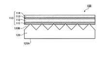
〔1〕 表示装置用光学部材であって、
光拡散板、及び反射性偏光子を含む偏光積層体を有し、
前記光拡散板は、その主面の少なくとも一方の有効領域内に凹凸構造を有し、
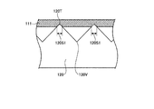
前記光拡散板及び前記偏光積層体は、前記有効領域の一部において、前記凹凸構造の凸部を介して接し、
前記凸部の頂部から、前記凸部の高さの1〜50%の範囲までの領域が、前記偏光積層体に埋没している光学部材。
〔2〕 前記凹凸構造が、複数の断面多角形状の線状プリズム又はレンチキュラーレンズを、その長手方向が主面に平行な方向に互いに平行に延長するよう設けた構造である前記光学部材。
〔3〕 前記凹凸構造が、角錐を隣接して敷き詰めた構造である前記光学部材。
〔4〕 前記凹凸構造が、粒子を平面上に分布させた構造である前記光学部材。
〔5〕 前記凹凸構造が、ポリマー及び透光性粒子を含有する混合物を、平滑な表面を有する基板上に展開してなる構造であることを特徴とする前記光学部材。
〔6〕 前記光拡散板と前記反射性偏光子とが、前記ポリマーを介して粘着されてなる、前記光学部材。
〔7〕 前記偏光積層体が粘着層を含み、前記光拡散板と前記反射性偏光子とが、前記粘着層を介して粘着されてなる、前記光学部材。
〔8〕 前記光拡散板の前記主面内の前記凹凸構造を有する領域における、算術平均粗さ最大値Ra(max)が1.0μm〜50μmである、前記光学部材。
〔9〕 反射板、複数の光源、前記光学部材、及び液晶セルを備える液晶表示装置。
[1] An optical member for a display device,
A polarizing laminate including a light diffusing plate and a reflective polarizer;
The light diffusing plate has a concavo-convex structure in at least one effective region of its main surface,
The light diffusing plate and the polarizing laminate are in contact with each other through a convex portion of the concave-convex structure in a part of the effective region,
The optical member in which the area | region from the top part of the said convex part to the range of 1-50% of the height of the said convex part is buried in the said polarizing laminated body.
[2] The optical member, wherein the concavo-convex structure is a structure in which a plurality of polygonal linear prisms or lenticular lenses are provided so that their longitudinal directions extend in parallel with each other in a direction parallel to the main surface.
[3] The optical member, wherein the uneven structure is a structure in which pyramids are adjacently spread.
[4] The optical member, wherein the uneven structure has a structure in which particles are distributed on a plane.
[5] The optical member, wherein the concavo-convex structure is a structure formed by developing a mixture containing a polymer and translucent particles on a substrate having a smooth surface.
[6] The optical member, wherein the light diffusing plate and the reflective polarizer are adhered via the polymer.
[7] The optical member, wherein the polarizing laminate includes an adhesive layer, and the light diffusion plate and the reflective polarizer are adhered via the adhesive layer.
[8] The optical member, wherein an arithmetic average roughness maximum value Ra (max) is 1.0 μm to 50 μm in a region having the concavo-convex structure in the main surface of the light diffusing plate.
[9] A liquid crystal display device comprising a reflector, a plurality of light sources, the optical member, and a liquid crystal cell.
本発明の光学部材は、これを組み込んだ液晶表示装置の輝度を向上させることができ、さらに耐熱性に優れる。したがって、これを備える本発明の液晶表示装置は、輝度が高く且つ長寿命な装置とすることができる。 The optical member of the present invention can improve the luminance of a liquid crystal display device incorporating the optical member, and further has excellent heat resistance. Therefore, the liquid crystal display device of the present invention including the above can be a device having high luminance and a long life.
1.光学部材
本発明の光学部材は、光拡散板及び偏光積層体を、所定の態様で有する。
1. Optical member The optical member of this invention has a light-diffusion plate and a polarizing laminated body in a predetermined | prescribed aspect.
1.1.光拡散板
本発明において、光拡散板は、その主面の少なくとも一方の有効領域内に、凹凸構造を有する凹凸領域を有する。
1.1. Light Diffusing Plate In the present invention, the light diffusing plate has a concavo-convex region having a concavo-convex structure in at least one effective region of its main surface.
ここで主面とは、平板状の拡散板の表面及び裏面であり、その一方が、拡散板へ光が入射する光入射面となり、他方が光拡散板から光が出射する光出射面となる。また、有効領域とは、かかる主面のうち、光の入射及び出射にかかわる領域である。即ち、有効領域内に凹凸構造を有するとは、光の入射及び出射に関わらない周辺領域のみに凹凸構造が設けられているのではなく、少なくとも、主面において、表示装置の表示にかかわる光が入射及び出射する領域において凹凸構造が設けられていることを意味する。有効領域は、その一部のみに凹凸領域を有していてもよいが、好ましくはその全面に凹凸領域を有する。 Here, the main surface is the front and back surfaces of a flat diffuser plate, one of which is a light incident surface on which light enters the diffuser plate, and the other is a light output surface from which light is emitted from the light diffuser plate. . The effective area is an area related to the incidence and emission of light in the main surface. That is, having an uneven structure in the effective region means that the uneven structure is not provided only in the peripheral region that is not related to the incidence and emission of light, but at least the light related to the display of the display device is displayed on the main surface. It means that a concavo-convex structure is provided in the incident and outgoing regions. The effective region may have a concavo-convex region only in a part thereof, but preferably has a concavo-convex region over the entire surface.
光拡散板は内部に空洞を有したものでも良く、空洞を有することで光拡散板の軽量化を図ることができる。かかる空洞の形状は、任意の形状とすることができるが、たとえば、光拡散板をその厚さ方向に平行な面で切断した断面から見た場合の形状として、円、四角、三角、多角形等の形状とすることができる。 The light diffusing plate may have a cavity inside, and the light diffusing plate can be reduced in weight by having the cavity. The shape of the cavity can be any shape. For example, as a shape when the light diffusing plate is viewed from a cross section cut along a plane parallel to the thickness direction, a circle, a square, a triangle, a polygon Or the like.
光拡散板の厚さは、0.4〜7.0mmの範囲とすることが、光学的性質並びに適度な強度及び重量の発現の観点から好ましい。 The thickness of the light diffusing plate is preferably in the range of 0.4 to 7.0 mm from the viewpoint of optical properties and appropriate strength and weight.
光拡散板の主面内の、凹凸構造を設けた領域の凹凸の高さは、特に限定されないが、かかる領域における算術平均粗さの最大値Ra(max)(主面内の様々な方向に沿って測定した算術平均粗さRaのうちの最大値)として、1.0μm〜50μmであることが好ましい。凹凸の深さをかかる範囲内とすることにより、後述する接触部分面積率を、容易に適切な範囲とすることができ好ましい。 The height of the unevenness in the region provided with the uneven structure in the main surface of the light diffusing plate is not particularly limited, but the maximum value Ra (max) of arithmetic average roughness in such region (in various directions in the main surface) It is preferable that it is 1.0-50 micrometers as the maximum value of arithmetic mean roughness Ra measured along. By setting the depth of the unevenness within such a range, it is preferable that a contact area ratio described later can be easily set to an appropriate range.
光拡散板上の凹凸構造としては、具体的には例えば、下記凹凸構造(i)〜(iii)を挙げることができる:
凹凸構造(i):複数の線状プリズム又はレンチキュラーレンズを、その長手方向が主面に平行な方向に、互いに平行に延長するよう設けた構造。
凹凸構造(ii):角錐を隣接して敷き詰めた構造。
凹凸構造(iii):各種の形状の粒子を平面上に分布させた構造。
Specific examples of the uneven structure on the light diffusion plate include the following uneven structures (i) to (iii):
Concave and convex structure (i): A structure in which a plurality of linear prisms or lenticular lenses are provided so that their longitudinal directions extend in parallel to each other in a direction parallel to the main surface.
Uneven structure (ii): A structure in which pyramids are spread adjacently.
Uneven structure (iii): A structure in which particles of various shapes are distributed on a plane.
凹凸構造(i)の線状プリズム又はレンチキュラーレンズの断面の形状は、(i-1)三角形、五角形、七角形、台形等の多角形;(i-2)半円形、円弧状等の円の一部の形状、楕円の一部の形状、放物線の形状、及びその他レンチキュラーレンズとして用いうる各種の曲面を与える、曲線を含む断面形状;又は(i-3)前記形状(i-1)の一部分と前記形状(i-2)の一部分とを組み合わせた形状とすることができる。 The cross-sectional shape of the linear prism or lenticular lens of the concavo-convex structure (i) is (i-1) a polygon such as a triangle, pentagon, heptagon or trapezoid; (i-2) a circle such as a semicircle or arc (I-3) a part of the shape (i-1); or (i-3) a cross-sectional shape including a curve that gives various shapes, a shape of a part of an ellipse, a parabola shape, and various other curved surfaces that can be used as a lenticular lens; And a part of the shape (i-2).
断面形状(i-1)を有する凹凸構造(i)の一例としては例えば、図7に示す光拡散板120の面上の、複数の断面三角形状の線状プリズム171が平行に延長してなるプリズム条列170を挙げることができる。この例において、線状プリズム171の頂角θ171は、40〜170°の範囲とすることができ、線状プリズム171のピッチP171は、20〜700μmの範囲とすることができ、また線状プリズムの高さH171は5〜650μmの範囲とすることができる。このような範囲において、良好な輝度及び輝度均斉度を得ることができ、且つ接触部分面積率を適切な範囲とすることができる。
As an example of the concavo-convex structure (i-1) having the cross-sectional shape (i-1), for example, a plurality of
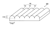
断面形状(i-2)を有する凹凸構造(i)の一例としては例えば、図8に示す光拡散板820の面上の、複数の断面半円形状のレンチキュラーレンズ181が平行に延長してなる構造180を挙げることができる。この例において、レンチキュラーレンズの断面を形成する曲線としては、円弧状、楕円弧状、放物線弧状としてもよい。レンチキュラーレンズ181の高さH181は、5〜100μmの範囲とすることができ、レンチキュラーレンズ181のピッチP181は20〜700μmの範囲とすることができる。このような範囲において、良好な輝度及び輝度均斉度を得ることができ、且つ接触部分面積率を適切な範囲とすることができる。
As an example of the concavo-convex structure (i) having the cross-sectional shape (i-2), for example, a plurality of semicircular
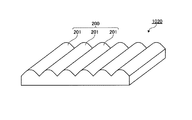
断面形状(i-3)を有する凹凸構造(i)の一例としては例えば、図10に示す光拡散板1020の面上の、三角形と円弧状の形状とを組み合わせた断面形状を有する線状プリズム201が平行に延長してなる構造200を挙げることができる。この例において、線状プリズム201の断面形状は、図11に示す通り、三角形を構成する斜辺の一部である辺Sにより構成される部分62と、当該三角形の頂部を円弧状の形状に置き換える曲線Cにより構成される部分61とからなる。ここで曲線Cの長さは、2本の辺S及び曲線Cの合計の40%以上の長さとすることができる。
As an example of the concavo-convex structure (i) having the cross-sectional shape (i-3), for example, a linear prism having a cross-sectional shape combining a triangle and an arc shape on the surface of the
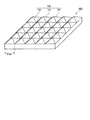
凹凸構造(ii)の角錐は、三角錐、四角錐等とすることができる。凹凸構造(ii)の一例としては例えば、図9に示す光拡散板920の面上の、複数の正四角錘191が、各々の底辺を隣接する四角錘と共有する態様で配列された構造を挙げることができる。この例において、正四角錘の底辺の長さP191は20〜700μmの範囲とすることができ、正四角錐の頂点を通り底辺の一辺に平行で光拡散板の主面に垂直な断面における正四角錐の頂角は、40〜170°の範囲とすることができる。このような範囲において、良好な輝度及び輝度均斉度を得ることができ、且つ接触部分面積率を適切な範囲とすることができる。
The pyramid of the concavo-convex structure (ii) can be a triangular pyramid, a quadrangular pyramid, or the like. As an example of the concavo-convex structure (ii), for example, a structure in which a plurality of regular
凹凸構造(i)を有する光拡散板及び凹凸構造(ii)を有する光拡散板は、凹凸構造部分及びその他の部分を同一の材料から一体に成形して得ることができる。 The light diffusing plate having the concavo-convex structure (i) and the light diffusing plate having the concavo-convex structure (ii) can be obtained by integrally molding the concavo-convex structure portion and other portions from the same material.
この場合の光拡散板の材質は、ガラス、混合しにくい2種以上の樹脂の混合物、透明樹脂に光拡散剤を分散させたもの、および1種類の透明樹脂等を用いることができる。これらの中で、軽量であること、成形が容易であることから樹脂が好ましく、輝度向上が容易である点からは1種類の透明樹脂が好ましく、全光線透過率とヘーズの調整が容易である点からは透明樹脂に光拡散剤を分散させたものが好ましい。
また、光拡散板の材質は板全体に均一である必要はなく、不均一であってもよい。例えば、光拡散板の厚み方向で光入射面に近い部分を構成する材料と光出射面に近い部分を構成する材料とが異なっていてもよい。または例えば、光拡散板の厚み方向で光入射面に近い部分を構成する材料と光出射面に近い部分を構成する材料とが異なり、さらにそれらの境界部分が明瞭なものではなく、境界部分において当該異なる材料が混合し、これらの材料の濃度が勾配を形成したものであってもよい。
The material of the light diffusing plate in this case may be glass, a mixture of two or more kinds of resins that are difficult to mix, a transparent resin in which a light diffusing agent is dispersed, a single type of transparent resin, and the like. Among these, a resin is preferable because it is lightweight and easy to mold, and one kind of transparent resin is preferable from the viewpoint that luminance can be easily improved, and adjustment of total light transmittance and haze is easy. From the viewpoint, a transparent resin in which a light diffusing agent is dispersed is preferable.
The material of the light diffusing plate does not need to be uniform throughout the plate, and may be non-uniform. For example, the material constituting the portion close to the light incident surface in the thickness direction of the light diffusing plate may be different from the material constituting the portion close to the light exit surface. Or, for example, the material constituting the portion near the light incident surface in the thickness direction of the light diffusing plate is different from the material constituting the portion near the light exit surface, and the boundary portion is not clear, and the boundary portion The different materials may be mixed and the concentration of these materials may form a gradient.
前記透明樹脂とは、JIS K7361−1に基づいて、両面平滑な2mm厚の板で測定した全光線透過率が70%以上の樹脂のことであり、例えば、ポリエチレン、プロピレン−エチレン共重合体、ポリプロピレン、ポリスチレン、芳香族ビニル単量体と低級アルキル基を有する(メタ)アクリル酸アルキルエステルとの共重合体、ポリエチレンテレフタレート、テレフタル酸−エチレングリコール−シクロヘキサンジメタノール共重合体、ポリカーボネート、アクリル樹脂、および脂環式構造を有する樹脂などを挙げることができる。なお、(メタ)アクリル酸とは、アクリル酸およびメタクリル酸のことである。 The transparent resin is a resin having a total light transmittance of 70% or more measured with a 2 mm-thick plate smooth on both sides based on JIS K7361-1, for example, polyethylene, propylene-ethylene copolymer, Polypropylene, polystyrene, copolymer of aromatic vinyl monomer and (meth) acrylic acid alkyl ester having a lower alkyl group, polyethylene terephthalate, terephthalic acid-ethylene glycol-cyclohexanedimethanol copolymer, polycarbonate, acrylic resin, And a resin having an alicyclic structure. In addition, (meth) acrylic acid is acrylic acid and methacrylic acid.
これらの中でも、透明樹脂としては、ポリカーボネート、ポリスチレン、芳香族ビニル単量体を10%以上含有する芳香族ビニル系単量体と低級アルキル基を有する(メタ)アクリル酸アルキルエステルとの共重合体、および脂環式構造を有する樹脂等の吸水率が0.25%以下である樹脂が、吸湿による変形が少ないので、反りの少ない大型の光拡散板を得ることができる点で好ましい。 Among these, as a transparent resin, a copolymer of polycarbonate, polystyrene, an aromatic vinyl monomer containing 10% or more of an aromatic vinyl monomer, and a (meth) acrylic acid alkyl ester having a lower alkyl group Further, a resin having a water absorption of 0.25% or less, such as a resin having an alicyclic structure, is preferable in that a large light diffusion plate with little warpage can be obtained because deformation due to moisture absorption is small.
脂環式構造を有する樹脂は、流動性が良好であり、大型の光拡散板を効率よく製造できる点でより好ましい。脂環式構造を有する樹脂と光拡散剤の混合物は、光拡散板に必要な高透過性と高拡散性とを兼ね備え、色度が良好なので、好適に用いることができる。 A resin having an alicyclic structure is more preferable because it has good fluidity and can efficiently produce a large light diffusion plate. A mixture of a resin having an alicyclic structure and a light diffusing agent has both high permeability and high diffusibility required for a light diffusing plate, and has good chromaticity, so that it can be suitably used.
脂環式構造を有する樹脂は、主鎖および/または側鎖に脂環式構造を有する樹脂である。機械的強度、耐熱性などの観点から、主鎖に脂環式構造を含有する樹脂が特に好ましい。脂環式構造としては、飽和環状炭化水素(シクロアルカン)構造、および不飽和環状炭化水素(シクロアルケン、シクロアルキン)構造などを挙げることができる。機械的強度、耐熱性などの観点から、シクロアルカン構造およびシクロアルケン構造が好ましく、中でもシクロアルカン構造が最も好ましい。脂環式構造を構成する炭素原子数は、通常4〜30個、好ましくは5〜20個、より好ましくは5〜15個の範囲であるときに、機械的強度、耐熱性及び光拡散板の成形性の特性が高度にバランスされ、好適である。 The resin having an alicyclic structure is a resin having an alicyclic structure in the main chain and / or side chain. From the viewpoint of mechanical strength, heat resistance, etc., a resin containing an alicyclic structure in the main chain is particularly preferred. Examples of the alicyclic structure include a saturated cyclic hydrocarbon (cycloalkane) structure and an unsaturated cyclic hydrocarbon (cycloalkene, cycloalkyne) structure. From the viewpoint of mechanical strength, heat resistance and the like, a cycloalkane structure and a cycloalkene structure are preferable, and among them, a cycloalkane structure is most preferable. When the number of carbon atoms constituting the alicyclic structure is usually in the range of 4 to 30, preferably 5 to 20, more preferably 5 to 15, the mechanical strength, heat resistance and light diffusion plate Formability characteristics are highly balanced and suitable.
脂環式構造を有する樹脂中の脂環式構造を有する繰り返し単位の割合は、使用目的に応じて適宜選択すればよいが、通常50重量%以上、好ましくは70重量%以上、より好ましくは90重量%以上である。脂環式構造を有する繰り返し単位の割合が過度に少ないと、耐熱性が低下し好ましくない。なお、脂環式構造を有する樹脂中における脂環式構造を有する繰り返し単位以外の繰り返し単位は、使用目的に応じて適宜選択される。 The proportion of the repeating unit having an alicyclic structure in the resin having an alicyclic structure may be appropriately selected according to the purpose of use, but is usually 50% by weight or more, preferably 70% by weight or more, more preferably 90%. % By weight or more. When the ratio of the repeating unit having an alicyclic structure is too small, the heat resistance is lowered, which is not preferable. In addition, repeating units other than the repeating unit which has an alicyclic structure in resin which has an alicyclic structure are suitably selected according to the intended purpose.
脂環式構造を有する樹脂の具体例としては、(1)ノルボルネン単量体の開環重合体及びノルボルネン単量体とこれと開環共重合可能なその他の単量体との開環共重合体、並びにこれらの水素添加物、ノルボルネン単量体の付加重合体及びノルボルネン系単量体とこれと共重合可能なその他の単量体との付加共重合体などのノルボルネン重合体;(2)単環の環状オレフィン重合体及びその水素添加物;(3)環状共役ジエン重合体及びその水素添加物;(4)ビニル脂環式炭化水素系単量体の重合体及びビニル脂環式炭化水素系単量体とこれと共重合可能なその他の単量体との共重合体、並びにこれらの水素添加物、ビニル芳香族単量体の重合体の芳香環の水素添加物及びビニル芳香族単量体とこれと共重合可能なその他の単量体との共重合体の芳香環の水素添加物などのビニル脂環式炭化水素重合体;などを挙げることができる。 Specific examples of the resin having an alicyclic structure include (1) a ring-opening polymer of a norbornene monomer and a ring-opening copolymer of the norbornene monomer and other monomers capable of ring-opening copolymerization Norbornene polymers such as hydrogenated products, addition polymers of norbornene monomers, and addition copolymers of norbornene monomers with other monomers copolymerizable therewith; (2) Monocyclic olefin polymer and hydrogenated product thereof; (3) Cyclic conjugated diene polymer and hydrogenated product thereof; (4) Polymer of vinyl alicyclic hydrocarbon monomer and vinyl alicyclic hydrocarbon Copolymers of monomers and other monomers copolymerizable therewith, as well as hydrogenated products thereof, aromatic ring hydrogenated products of vinyl aromatic monomers, and vinyl aromatic monomers. Copolymerization of the monomer and other monomers copolymerizable therewith Vinyl alicyclic hydrocarbon polymers such as hydrogenated products of the body of the aromatic ring; and the like.
これらの中でも、耐熱性、機械的強度等の観点から、ノルボルネン重合体およびビニル脂環式炭化水素重合体が好ましく、ノルボルネン単量体の開環重合体水素添加物、ノルボルネン単量体とこれと開環共重合可能なその他の単量体との開環共重合体水素添加物、ビニル芳香族単量体の重合体の芳香環の水素添加物及びビニル芳香族単量体とこれと共重合可能なその他の単量体との共重合体の芳香環の水素添加物がさらに好ましい。 Among these, from the viewpoints of heat resistance, mechanical strength, and the like, norbornene polymers and vinyl alicyclic hydrocarbon polymers are preferred, and ring-opening polymer hydrogenated products of norbornene monomers, norbornene monomers, and Hydrogenation of ring-opening copolymer with other monomers capable of ring-opening copolymerization, hydrogenation of aromatic ring of polymer of vinyl aromatic monomer, and copolymerization with vinyl aromatic monomer and this More preferred are hydrogenated aromatic rings of copolymers with other possible monomers.
前記光拡散剤は、光線を拡散させる性質を有する粒子であり、無機フィラーと有機フィラーとに大別できる。無機フィラーとしては、シリカ、水酸化アルミニウム、酸化アルミニウム、酸化チタン、酸化亜鉛、硫酸バリウム、マグネシウムシリケート、およびこれらの混合物を挙げることができる。有機フィラーとしては、アクリル樹脂、ポリウレタン、ポリ塩化ビニル、ポリスチレン樹脂、ポリアクリロニトリル、ポリアミド、ポリシロキサン樹脂、メラミン樹脂、およびベンゾグアナミン樹脂等を挙げることができる。これらの中でも、有機フィラーとしては、ポリスチレン樹脂、ポリシロキサン樹脂、およびこれらの架橋物からなる微粒子が、高分散性、高耐熱性、成形時の着色(黄変)がない点で好ましく、これらの中でも、より耐熱性に優れる点でポリシロキサン樹脂の架橋物からなる微粒子がより好ましい。 The light diffusing agent is a particle having a property of diffusing light, and can be roughly classified into an inorganic filler and an organic filler. Examples of the inorganic filler include silica, aluminum hydroxide, aluminum oxide, titanium oxide, zinc oxide, barium sulfate, magnesium silicate, and a mixture thereof. Examples of the organic filler include acrylic resin, polyurethane, polyvinyl chloride, polystyrene resin, polyacrylonitrile, polyamide, polysiloxane resin, melamine resin, and benzoguanamine resin. Among these, as the organic filler, fine particles composed of polystyrene resin, polysiloxane resin, and cross-linked products thereof are preferable in terms of high dispersibility, high heat resistance, and no coloration (yellowing) during molding. Among these, fine particles made of a cross-linked product of polysiloxane resin are more preferable from the viewpoint of more excellent heat resistance.
前記光拡散剤の形状としては、例えば、球状、立方状、針状、棒状、紡錘形状、板状、鱗片状、および繊維状などを挙げることができ、これらの中でも、光の拡散方向を等方的にできる点で球状が好ましい。前記光拡散剤は、透明樹脂内に均一に分散された状態で使用される。 Examples of the shape of the light diffusing agent include a spherical shape, a cubic shape, a needle shape, a rod shape, a spindle shape, a plate shape, a scale shape, and a fiber shape. Among these, the light diffusing direction can be exemplified. Spherical shape is preferable in that it can be squarely. The light diffusing agent is used in a state of being uniformly dispersed in the transparent resin.
透明樹脂に分散させる光拡散剤の割合は、光拡散板の厚みや、線状光源の間隔などに応じて適宜選択できるが、通常は、分散物の全光線透過率が60%〜98%となるように光拡散剤の含有量を調整することが好ましく、65%〜95%となるように光拡散剤の含有量を調整することがより好ましい。全光線透過率を上記好適な範囲とすることにより、輝度および輝度均斉度をより向上させることができる。 The ratio of the light diffusing agent dispersed in the transparent resin can be appropriately selected according to the thickness of the light diffusing plate, the interval between the linear light sources, and the like. Usually, the total light transmittance of the dispersion is 60% to 98%. It is preferable to adjust the content of the light diffusing agent so as to be, and it is more preferable to adjust the content of the light diffusing agent to be 65% to 95%. By setting the total light transmittance within the above preferable range, the luminance and the luminance uniformity can be further improved.
なお、全光線透過率とは、JIS K7361-1に基づいて、両面平滑な2mm厚みの板で測定した値であり、ヘーズとはJIS K7136により両面平滑な2mm厚みの板で測定した値である。 The total light transmittance is a value measured with a 2 mm-thick plate smoothed on both sides based on JIS K7361-1, and the haze is a value measured on a 2 mm-thick plate smoothed on both sides with JIS K7136. .
凹凸構造(i)又は(ii)を有する光拡散板の成形方法は、特に限定されず、射出成形、押出成形、キュスティング型を用いたキャスト法などの任意の成形方法をとることができる。より具体的には、前記凹凸構造に対応した形状を有するスタンパを含む型を調製し、これを用いて射出成形を行なうことにより、効率的に製造を行なうことができる。 The molding method of the light diffusing plate having the concavo-convex structure (i) or (ii) is not particularly limited, and any molding method such as injection molding, extrusion molding, or casting method using a casting mold can be employed. More specifically, it is possible to manufacture efficiently by preparing a mold including a stamper having a shape corresponding to the concavo-convex structure and performing injection molding using the mold.
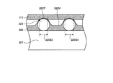
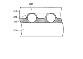
一方、凹凸構造(iii)を有する光拡散板は、ポリマー及び/又は重合性モノマーと所望の形状の透光性粒子とを含有する混合物(以下「凹凸構造用混合物」という。)を、平滑な表面を有する基板上に展開して凹凸構造用混合物の層を得、前記混合物の層を硬化させて得ることができる。 On the other hand, the light diffusing plate having the concavo-convex structure (iii) is a smooth mixture (hereinafter referred to as “concavo-convex structure mixture”) containing a polymer and / or a polymerizable monomer and translucent particles having a desired shape. It can be obtained by spreading on a substrate having a surface to obtain a layer of the mixture for uneven structure and curing the layer of the mixture.
ここで、透光性粒子の形状は、例えば球、球に近似した曲面からなる形状、多面体、曲面及び平面からなる形状等の形状とすることができる。球に近似した曲面からなる形状としては、楕円球等の形状を挙げることができる。また多面体としては、角柱、角錐、その他の多面体(例えば、正八面体、正十二面体、正二十面体等の正多面体、切頂二十面体等の半正多面体、及びこれらに近い形状)を挙げることができる。また曲面及び平面からなる形状としては、円錐、楕円錐、円柱、楕円柱等の形状を挙げることができる。 Here, the shape of the translucent particles can be, for example, a shape such as a sphere, a shape made of a curved surface approximated to a sphere, a shape made of a polyhedron, a curved surface, and a flat surface. Examples of the shape made of a curved surface that approximates a sphere include an elliptic sphere. Polyhedrons include prisms, pyramids, and other polyhedrons (for example, regular octahedrons, regular dodecahedrons, regular icosahedrons, etc., regular polyhedrons such as truncated icosahedrons, and shapes close to these). Can be mentioned. In addition, examples of the shape composed of a curved surface and a flat surface include shapes such as a cone, an elliptical cone, a cylinder, and an elliptic cylinder.
凹凸構造用混合物に用いる透光性粒子の材質は、例えば有機材料としては、アクリル樹脂、ポリウレタン、ポリ塩化ビニル、ポリスチレン樹脂、ポリアクニロニトリル、ポリアミド、ポリシロキサン樹脂、メラミン樹脂、ベンゾグアナミン樹脂を挙げることができる。無機系材料としては、シリカ、酸化アルミニウム、酸化チタン、酸化亜鉛、硫酸バリウム、マグネシウムシリケートを挙げることができる。またこれらの混合物も使用することができる。
凹凸構造用混合物に用いる粒子の寸法は、平均粒子径として10〜100μmの範囲であることが、所望の寸法の凹凸構造を得る観点から好ましい。ここで、平均粒子径とは、透光性粒子を蒸留水に3重量パーセントで分散し、レーザー回折散乱法により体積基準にて粒度分布を測定し、算出した個数平均粒子径である。
凹凸構造用混合物において、透光性粒子の含有割合は、ポリマー、重合性モノマー、及び透光性粒子の合計に対して2〜60重量%とすることができる。
Examples of the material of the translucent particles used in the uneven structure mixture include, for example, an acrylic resin, polyurethane, polyvinyl chloride, polystyrene resin, polyacrylonitrile, polyamide, polysiloxane resin, melamine resin, and benzoguanamine resin as the organic material. be able to. Examples of inorganic materials include silica, aluminum oxide, titanium oxide, zinc oxide, barium sulfate, and magnesium silicate. Mixtures of these can also be used.
The size of the particles used in the concavo-convex structure mixture is preferably in the range of 10 to 100 μm as an average particle diameter from the viewpoint of obtaining a concavo-convex structure having a desired size. Here, the average particle diameter is a number average particle diameter calculated by dispersing translucent particles in distilled water at 3 weight percent, measuring the particle size distribution on a volume basis by a laser diffraction scattering method.
In the concavo-convex structure mixture, the content ratio of the light-transmitting particles can be 2 to 60% by weight based on the total of the polymer, the polymerizable monomer, and the light-transmitting particles.
凹凸構造用混合物に用いるポリマーとしては、例えばアクリル系重合体および共重合体、シリコーン系ポリマー、ポリエステル、ポリウレタン、ポリアミド、ポリビニルエーテル、ポリビニルアルコール、ポリビニルアセタール、エチレン酢酸ビニル共重合体、エチレンアクリル酸エステル共重合体、エチレン塩化ビニル共重合体、熱可塑性エラストマー、エポキシ系、フェノール系、合成ゴム系、又はこれらの混合物を用いることができる。好ましい樹脂は、耐光性に優れているアクリル系重合体である。凹凸構造用混合物は、必要に応じてトルエン、キシレン、酢酸エチル、酢酸ブチル、酢酸イソブチル、メチルエチルケトン、メチルイソブチルケトン、シクロペンタノン、シクロヘキサノン、メタノール、エタノール、イソプロピルアルコール、n−プロピルアルコール、n−ブチルアルコール、イソブチルアルコール、2−メトキシエタノール、2−ブトキシエタノール等の溶剤を含有することができる。 Examples of the polymer used in the uneven structure mixture include acrylic polymers and copolymers, silicone polymers, polyesters, polyurethanes, polyamides, polyvinyl ethers, polyvinyl alcohols, polyvinyl acetals, ethylene vinyl acetate copolymers, and ethylene acrylic esters. A copolymer, an ethylene vinyl chloride copolymer, a thermoplastic elastomer, an epoxy system, a phenol system, a synthetic rubber system, or a mixture thereof can be used. A preferred resin is an acrylic polymer having excellent light resistance. The concavo-convex structure mixture may be toluene, xylene, ethyl acetate, butyl acetate, isobutyl acetate, methyl ethyl ketone, methyl isobutyl ketone, cyclopentanone, cyclohexanone, methanol, ethanol, isopropyl alcohol, n-propyl alcohol, n-butyl as necessary. Solvents such as alcohol, isobutyl alcohol, 2-methoxyethanol, 2-butoxyethanol can be contained.
凹凸構造用混合物に用いる重合性モノマーとしては、(メタ)アクリロイル基を有する単官能又は多官能のモノマーを用いることができる。
(メタ)アクリロイル基を有する単官能のモノマーとしては、(メタ)アクリル酸などのアクリル酸類、エチレンオキサイド変性フェノールの(メタ)アクリレート、プロピレンオキサイド変性フェノールの(メタ)アクリレート、エチレンオキサイド変性ノニルフェノールの(メタ)アクリレート、プロピレンオキサイド変性ノニルフェノールの(メタ)アクリレート、2−エチルヘキシルカルビトール(メタ)アクリレート、イソボニル(メタ)アクリレート、テトラヒドロフルフリル(メタ)アクリレート、ヒドロキシエチル(メタ)アクリレート、ヒドロキシプロピル(メタ)アクリレート、ヒドロキシブチルモノ(メタ)アクリレート、ヒドロキシヘキシルモノ(メタ)アクリレート、ジエチレングリコールモノ(メタ)アクリレート、ジプロピレングリコールモノ(メタ)アクリレート、トリエチレングリコールモノ(メタ)アクリレート、トリプロピレングリコールモノ(メタ)アクリレート、メチル(メタ)アクリレート、ブチル(メタ)アクリレート、2−エチルヘキシル(メタ)アクリレート、アクリロニトリル、グリシジル(メタ)アクリレートなどを挙げることができる。
(メタ)アクリロイル基を有する多官能のモノマーとしては、ジエチレングリコールジ(メタ)アクリレート、トリエチレングリコールジ(メタ)アクリレート、テトラエチレングリコールジ(メタ)アクリレート、ジプロピレングリコールジ(メタ)アクリレート、トリプロピレングリコールジ(メタ)アクリレート、テトラプロピレングリコールジ(メタ)アクリレート、ポリプロピレングリコールジ(メタ)アクリレート、1、4−ブタンジオールジ(メタ)アクリレート、ネオペンチルグリコールジ(メタ)アクリレート、エチレンオオキサイド変性ネオペンチルグリコールのジ(メタ)アクリレート、エチレンオキサイド変性ビスフェノールAのジ(メタ)アクリレート、プロピレンオキサイド変性ビスフェノールAのジ(メタ)アクリレート、エチレンオキサイド変性水添ビスフェノールAのジ(メタ)アクリレート、トリメチロールプロパンジ(メタ)アクリレート、トリメチロールプロパンアリルエーテルジ(メタ)アクリレート、トリメチロールプロパントリ(メタ)アクリレート、エチレンオキサイド変性トリメチロールプロパントリ(メタ)アクリレート、プロピレンオキサイド変性トリメチロールプロパントリ(メタ)アクリレート、ペンタエリスリトールトリ(メタ)アクリレート、ペンタエリスリトールテトラ(メタ)アクリレート、ペンタエリスリトールヘキサ(メタ)アクリレートなどを挙げることができる。
(メタ)アクリロイル基を有するモノマーとしては、この他に、単官能又は多官能のポリエステルアクリレート、ウレタンアクリレート、ポリオールアクリレートなどが挙げられる。これらの重合性モノマーは1種単独または2種以上を組み合わせて用いることができる。
As the polymerizable monomer used in the uneven structure mixture, a monofunctional or polyfunctional monomer having a (meth) acryloyl group can be used.
Monofunctional monomers having a (meth) acryloyl group include acrylic acids such as (meth) acrylic acid, (meth) acrylates of ethylene oxide-modified phenol, (meth) acrylates of propylene oxide-modified phenol, ( (Meth) acrylate, propylene oxide modified nonylphenol (meth) acrylate, 2-ethylhexyl carbitol (meth) acrylate, isobornyl (meth) acrylate, tetrahydrofurfuryl (meth) acrylate, hydroxyethyl (meth) acrylate, hydroxypropyl (meth) Acrylate, hydroxybutyl mono (meth) acrylate, hydroxyhexyl mono (meth) acrylate, diethylene glycol mono (meth) acrylate Dipropylene glycol mono (meth) acrylate, triethylene glycol mono (meth) acrylate, tripropylene glycol mono (meth) acrylate, methyl (meth) acrylate, butyl (meth) acrylate, 2-ethylhexyl (meth) acrylate, acrylonitrile And glycidyl (meth) acrylate.
The polyfunctional monomer having a (meth) acryloyl group includes diethylene glycol di (meth) acrylate, triethylene glycol di (meth) acrylate, tetraethylene glycol di (meth) acrylate, dipropylene glycol di (meth) acrylate, and tripropylene. Glycol di (meth) acrylate, tetrapropylene glycol di (meth) acrylate, polypropylene glycol di (meth) acrylate, 1,4-butanediol di (meth) acrylate, neopentyl glycol di (meth) acrylate, ethylene oxide modified neo Di (meth) acrylate of pentyl glycol, di (meth) acrylate of ethylene oxide modified bisphenol A, di (meth) of propylene oxide modified bisphenol A Chryrate, ethylene oxide modified hydrogenated bisphenol A di (meth) acrylate, trimethylolpropane di (meth) acrylate, trimethylolpropane allyl ether di (meth) acrylate, trimethylolpropane tri (meth) acrylate, ethylene oxide modified trimethylol Examples thereof include propane tri (meth) acrylate, propylene oxide-modified trimethylolpropane tri (meth) acrylate, pentaerythritol tri (meth) acrylate, pentaerythritol tetra (meth) acrylate, and pentaerythritol hexa (meth) acrylate.
Other examples of the monomer having a (meth) acryloyl group include monofunctional or polyfunctional polyester acrylate, urethane acrylate, and polyol acrylate. These polymerizable monomers can be used alone or in combination of two or more.
重合性モノマーを用いる場合には、任意に光重合開始剤や光増感剤を用いることができる。
光重合開始剤としては、アセトフェノン類、ベンゾフェノン類、α−アミロキシムエステル、テトラメチルチュラニウムモノサルファイド、チオキサントン類などが挙げられる。また光増感剤としてn−ブチルアミン、トリエチルアミン、ポリ−n−ブチルホスフィンなどが挙げられる。
When a polymerizable monomer is used, a photopolymerization initiator or a photosensitizer can be arbitrarily used.
Examples of the photopolymerization initiator include acetophenones, benzophenones, α-amyloxime esters, tetramethylchuranium monosulfide, thioxanthones, and the like. Examples of the photosensitizer include n-butylamine, triethylamine, and poly-n-butylphosphine.
凹凸構造用混合物には、さらに架橋剤、硬化剤を混合してもよい。
上記架橋剤又は硬化剤としては、トリレンジイソシアネート、ヘキサメチレンジイソシアネート、テトラメチレンジイソシアネート、トリメチロールプロパントリレンジイソシアネート、ジフェニルメタントリイソシアネートなどの多官能イソシアネート架橋剤又は硬化剤;エチレングリコールグリシジルエーテル、ポリエチレングリコールジグリシジルエーテル、ジグリシジルエーテル、トリメチロールプロパントリグリシジルエーテル、などのエポキシ系架橋剤又は硬化剤;ビニルトリメトキシシラン、メタクリロキシプロピルトリメトキシシラン、3−グリシドキシプロピルトリメトキシシラン,2−(3,4−エポキシシクロヘキシル)エチルトリメトキシシラン、3−アミノプロピルトリメトキシシラン,N−(2−アミノエチル)3−アミノプロピルトリメトキシシランなどのシラン系架橋剤又は硬化剤を用いることができる。
架橋剤または硬化剤の配合量は、凹凸構造用混合物中のポリマー及び/又は重合性モノマー100重量部に対して、好ましくは0.1〜20重量部である。0.1重量部より少ないとポリマーの架橋の効果が発現せず、耐候性試験での発泡や剥離が目立つことがあり好ましくない。10重量部より多いと、ポリマーの硬化が進みすぎて基板との密着性が低下することがあり好ましくない。
You may mix a crosslinking agent and a hardening | curing agent with the mixture for uneven | corrugated structures further.
Examples of the crosslinking agent or curing agent include polyfunctional isocyanate crosslinking agents such as tolylene diisocyanate, hexamethylene diisocyanate, tetramethylene diisocyanate, trimethylolpropane tolylene diisocyanate, diphenylmethane triisocyanate; ethylene glycol glycidyl ether, polyethylene glycol di Epoxy crosslinking agents or curing agents such as glycidyl ether, diglycidyl ether, trimethylolpropane triglycidyl ether; vinyltrimethoxysilane, methacryloxypropyltrimethoxysilane, 3-glycidoxypropyltrimethoxysilane, 2- (3 , 4-Epoxycyclohexyl) ethyltrimethoxysilane, 3-aminopropyltrimethoxysilane, N- (2-aminoethyl) Silane-based crosslinking agents or curing agents such as 3-aminopropyltrimethoxysilane can be used.
The amount of the crosslinking agent or curing agent is preferably 0.1 to 20 parts by weight with respect to 100 parts by weight of the polymer and / or polymerizable monomer in the uneven structure mixture. When the amount is less than 0.1 part by weight, the effect of crosslinking the polymer is not exhibited, and foaming and peeling in a weather resistance test are conspicuous, which is not preferable. When the amount is more than 10 parts by weight, the curing of the polymer proceeds so much that the adhesion to the substrate may be lowered, which is not preferable.
一方、凹凸構造(iii)を有する光拡散板の製造に用いる基板の材料は、上記凹凸構造(i)又は(ii)を有する光拡散板の材料と同様のものとすることができ、所望の型を用いて平滑な表面を有する基板に成形することができる。 On the other hand, the material of the substrate used for manufacturing the light diffusing plate having the concavo-convex structure (iii) can be the same as the material of the light diffusing plate having the concavo-convex structure (i) or (ii). A mold can be used to form a substrate having a smooth surface.
上記のもの等の凹凸構造用混合物を、基板の表面に塗布するなどして展開して凹凸構造用混合物の層を得、この層を乾燥、加熱、エネルギー線照射等の工程により硬化させることにより、凹凸構造(iii)を有する光拡散板を得ることができる。
凹凸構造用混合物を基板の表面に塗布する方法としては、スプレー法、ディッピング法、スピンコート法などの、枚葉状の基板状に液体を塗布する際に用いられる公知の塗工方法を挙げることができる。
By applying the concavo-convex structure mixture such as the above to the surface of the substrate and developing it to obtain a layer of the concavo-convex structure mixture, and curing the layer by a process such as drying, heating, energy ray irradiation, etc. A light diffusing plate having a concavo-convex structure (iii) can be obtained.
Examples of the method for applying the concavo-convex structure mixture to the surface of the substrate include known coating methods used when applying a liquid to a single-wafer substrate, such as a spray method, a dipping method, and a spin coating method. it can.
凹凸構造(iii)を有する光拡散板の、さらに別の作製方法として、以下の工程(イ)〜(ニ)を含む方法を挙げることができる。
(イ)凹凸構造用混合物を、剥離力の小さい第1の転写用フィルム上に塗工して凹凸構造用混合物の層を得、かかる層を硬化させて、凹凸構造層と第1の転写用フィルムとの積層体を作製する。
(ロ)(イ)で得た積層体の凹凸構造層側の面に、第1の転写用フィルムより剥離力の大きい第2の転写用フィルムを貼り合わせて、第2の転写用フィルム−凹凸構造層−第1の転写用フィルムの層構成を有する積層体を作製する。
(ハ)(ロ)で得た積層体から第1の転写用フィルムを剥離し、第2の転写用フィルム−凹凸構造層の層構成を有する積層体を作製する。
(ニ)(ハ)で得た積層体の凹凸構造層側の面を、光拡散板の構成要素である基板の表面に貼り合わせて、第2の転写用フィルムを剥離し、凹凸構造層−基板の層構成を有する、凹凸構造(iii)を有する光拡散板を得る。
As another production method of the light diffusing plate having the concavo-convex structure (iii), a method including the following steps (A) to (D) can be exemplified.
(A) The concavo-convex structure mixture is coated on the first transfer film having a small peeling force to obtain a layer of the concavo-convex structure mixture, and the layer is cured to form the concavo-convex structure layer and the first transfer layer. A laminate with a film is prepared.
(B) A second transfer film-concave pattern is formed by laminating a second transfer film having a larger peeling force than the first transfer film on the surface of the laminate structure obtained in (a) on the concave-convex structure layer side. A laminate having a layer structure of structural layer-first transfer film is prepared.
(C) The first transfer film is peeled from the laminate obtained in (b) to produce a laminate having a second transfer film-concave structure layer structure.
(D) The uneven structure layer side surface of the laminate obtained in (c) is bonded to the surface of the substrate, which is a constituent element of the light diffusion plate, and the second transfer film is peeled off, and the uneven structure layer- A light diffusion plate having a concavo-convex structure (iii) having a layer structure of the substrate is obtained.
ここで、フィルムの剥離力とは、フィルムと凹凸構造層との界面を剥離するのに要する力である。したがって剥離力が大きいフィルムとは、かかるフィルムと凹凸構造層との界面を剥離するのに要する力が大きいフィルムであり、一方剥離力が小さいフィルムとは、かかるフィルムと凹凸構造層との界面を剥離するのに要する力が小さいフィルムである。
前記工程(イ)〜(ニ)の全部又は一部は、長尺の製品を製造しうる製造ラインにおいて連続的に行なうことができ、かかる連続的な製造により、光拡散板を効率的に得ることができる。特に、凹凸構造用混合物を第1の転写用フィルムに塗工する工程を、連続的に行なうことが好ましい。かかる連続的な塗工を行なう具体的な方法としては、スプレー法、ディッピング法、ロールコーター法、ダイコート法、カーテンフロー法、メイヤーバー法、マイクログラビア法などの公知の方法が挙げられる。
Here, the peeling force of the film is a force required to peel the interface between the film and the concavo-convex structure layer. Therefore, a film having a large peel force is a film having a large force required to peel the interface between the film and the concavo-convex structure layer, while a film having a small peel force is a film having the interface between the film and the concavo-convex structure layer. It is a film that requires little force to peel off.
All or part of the steps (a) to (d) can be continuously performed in a production line capable of producing a long product, and the light diffusing plate is efficiently obtained by such continuous production. be able to. In particular, it is preferable to continuously perform the step of applying the uneven structure mixture to the first transfer film. Specific methods for performing such continuous coating include known methods such as spraying, dipping, roll coater, die coating, curtain flow, Mayer bar, and microgravure.
前記第1及び第2の転写用フィルムとしては、具体的には例えばPET(ポリエチレンテレフタレート)製フィルムを用いることができる。また、フィルムの剥離力は、フィルムの表面処理等により適宜調節することができる。
フィルムの表面処理方法としては、表面張力の小さいシリコーン樹脂、フッ素樹脂材料を溶解あるいは分散させた塗工液を公知の方法でフィルム表面に塗工し、乾燥する方法、フィルム表面をコロナ処理、火炎処理、プラズマ処理する方法が挙げられる。
Specifically, for example, a film made of PET (polyethylene terephthalate) can be used as the first and second transfer films. Moreover, the peeling force of a film can be suitably adjusted with the surface treatment etc. of a film.
As a film surface treatment method, a coating solution in which a silicone resin having a low surface tension or a fluororesin material is dissolved or dispersed is applied to the film surface by a known method and dried, the film surface is corona treated, flame The method of processing and plasma processing is mentioned.
基板に前記凹凸構造用混合物を塗布する際の塗膜の厚さを、透光性粒子の直径より薄いものとすることにより、塗膜の面上から透光性粒子の形状の一部を突出させ、所望の凹凸構造を得ることができる。透光性粒子が突出した部分以外の塗膜の厚さは、透光性粒子の直径の6〜50%とすることが好ましい。 A part of the shape of the translucent particles protrudes from the surface of the coating film by making the thickness of the coating film when applying the concavo-convex structure mixture on the substrate smaller than the diameter of the translucent particles. Thus, a desired concavo-convex structure can be obtained. The thickness of the coating film other than the portion where the translucent particles protrude is preferably 6 to 50% of the diameter of the translucent particles.
透光性粒子間のピッチは、10〜100μmの範囲にあることが好ましい。かかるピッチは、隣接する粒子の端部と端部の最短距離5点の平均を求め、これを必要に応じて凹凸領域中の複数の観察視野において行い平均を求めることによって求めることができる。 The pitch between the translucent particles is preferably in the range of 10 to 100 μm. Such a pitch can be obtained by obtaining an average of five points at the shortest distance between the ends of adjacent particles, and obtaining the average by performing this in a plurality of observation fields in the uneven region as necessary.
1.2.偏光積層体
本発明において、偏光積層体は、反射性偏光子のみからなるか、又は反射性偏光子とその他の層とが積層されてなる構成要素である。反射性偏光子以外の層は任意に設けうる層である。説明の便宜上、本発明においては反射性偏光子のみからなり複数層の積層構造を有しないものも「偏光積層体」に含まれる。
1.2. Polarizing Laminate In the present invention, the polarizing laminate is a component composed of only a reflective polarizer or a laminate of a reflective polarizer and other layers. Layers other than the reflective polarizer can be provided arbitrarily. For convenience of explanation, in the present invention, the “polarizing laminate” includes only a reflective polarizer and does not have a multilayer structure.
(反射性偏光子)
反射性偏光子は、それに入射した光の一部の偏光を透過させ、残りの偏光の少なくとも一部を反射する性質を有する。
反射性偏光子には、ある円偏光を透過させ残りの光を反射させる円偏光分離素子、及びある直線偏光を透過させ残りの光を反射させる直線偏光分離素子が含まれる。
(Reflective polarizer)
The reflective polarizer has a property of transmitting a part of the polarized light incident thereon and reflecting at least a part of the remaining polarized light.
The reflective polarizer includes a circularly polarized light separating element that transmits certain circularly polarized light and reflects the remaining light, and a linearly polarized light separating element that transmits certain linearly polarized light and reflects the remaining light.
(円偏光分離素子:コレステリック樹脂層)
代表的な円偏光分離素子としては、コレステリック樹脂層が挙げられる。コレステリック樹脂層は、樹脂層形成用基材上にコレステリック液晶組成物の塗膜を設け、塗膜を硬化させてなる、コレステリック規則性を有する層である。
コレステリック規則性とは、一平面上では分子軸が一定の方向に並んでいるが、次の平面では分子軸の方向が少し角度をなしてずれ、さらに次の平面ではさらに角度がずれるという具合に、分子が一定方向に配列している平面を進むに従って分子軸の角度がずれて(ねじれて)いく構造である。このように分子軸の方向がねじれてゆく構造は光学的にカイラルな構造となる。
(Circularly polarized light separating element: cholesteric resin layer)
A typical circularly polarized light separating element includes a cholesteric resin layer. The cholesteric resin layer is a layer having a cholesteric regularity obtained by providing a coating film of a cholesteric liquid crystal composition on a substrate for forming a resin layer and curing the coating film.
Cholesteric regularity means that the molecular axes are aligned in a certain direction on one plane, but the direction of the molecular axis is slightly shifted on the next plane, and the angle is further shifted on the next plane. This is a structure in which the angle of the molecular axis is shifted (twisted) as it advances through a plane in which molecules are arranged in a certain direction. Thus, the structure in which the direction of the molecular axis is twisted becomes an optically chiral structure.
本発明においては、この円偏光分離機能を可視光の全波長領域にわたって発揮するコレステリック樹脂層を備えることが好ましい。例えば、青色(波長410〜470nm)、緑色(波長520〜580nm)、赤色(波長600〜660)nmのいずれの波長域の光についても円偏光分離機能を有するコレステリック樹脂層であることが好ましい。 In this invention, it is preferable to provide the cholesteric resin layer which exhibits this circularly polarized light separation function over the entire wavelength region of visible light. For example, a cholesteric resin layer having a circularly polarized light separation function is preferable for light in any wavelength region of blue (wavelength 410 to 470 nm), green (wavelength 520 to 580 nm), and red (wavelength 600 to 660 nm).
円偏光分離機能を発揮する波長は、コレステリック樹脂におけるらせん構造のピッチに依存する。らせん構造のピッチとは、らせん構造において分子軸の方向が平面を進むに従って少しずつ角度がずれていき、そして再びもとの分子軸方向に戻るまでの平面法線方向の距離のことである。このらせん構造のピッチの大きさを変えることによって、円偏光分離機能を発揮する波長を変えることができる。 The wavelength that exhibits the circularly polarized light separation function depends on the pitch of the helical structure in the cholesteric resin. The pitch of the helical structure is a distance in the plane normal direction until the angle of the molecular axis in the helical structure gradually shifts as it advances along the plane and then returns to the original molecular axis direction again. By changing the pitch of the helical structure, the wavelength at which the circularly polarized light separating function is exhibited can be changed.
本発明に用いるコレステリック樹脂層は、重合性液晶性化合物を含むコレステリック液晶組成物を、後述する硬化の処理において重合して得ることができる。かかる層は、液晶性化合物の分子配向を呈したまま硬化した非液晶性の樹脂層となる。なお、ここで便宜上液晶組成物と称する材料は、2以上の物質の混合物のみならず、単一の物質からなる材料をも包含する。 The cholesteric resin layer used in the present invention can be obtained by polymerizing a cholesteric liquid crystal composition containing a polymerizable liquid crystal compound in a curing treatment described later. Such a layer becomes a non-liquid crystalline resin layer cured while exhibiting the molecular orientation of the liquid crystalline compound. Note that the material referred to as a liquid crystal composition here for convenience includes not only a mixture of two or more substances but also a material made of a single substance.
本発明に用いるコレステリック樹脂層としては、例えば、(i)らせん構造のピッチの大きさを段階的に変化させたコレステリック樹脂層、(ii)らせん構造のピッチの大きさを連続的に変化させたコレステリック樹脂層等が挙げられる。 As the cholesteric resin layer used in the present invention, for example, (i) a cholesteric resin layer in which the pitch of the helical structure is changed stepwise, and (ii) the pitch of the helical structure is continuously changed. A cholesteric resin layer etc. are mentioned.
(i)らせん構造のピッチを段階的に変化させたコレステリック樹脂層は、例えば、青色の波長域の光で円偏光分離機能を発揮するらせん構造のピッチを有するコレステリック樹脂層、緑色の波長域の光で円偏光分離機能を発揮するらせん構造のピッチを有するコレステリック樹脂層及び赤色の波長域の光で円偏光分離機能を発揮するらせん構造のピッチを有するコレステリック樹脂層を積層することによって得ることができる。具体的には例えば、反射される円偏光の中心波長が470nm、550nm、640nm、及び770nmといった複数種類のコレステリック樹脂層をそれぞれ作製し、これらのコレステリック樹脂層を任意に選択し、反射光の中心波長の順序で3〜7層積層することによって得ることができる。らせん構造のピッチの大きさが異なるコレステリック樹脂層を積層する場合には、各コレステリック樹脂層で反射する円偏光の回転方向が同じであることが好ましい。また、らせん構造のピッチの大きさが異なるコレステリック樹脂層の積層順序は、らせん構造のピッチの大きさで、昇順又は降順になるようにすることが、視野角の広い液晶表示装置を得るために好ましい。これらコレステリック樹脂層の積層は、粘着層を介して固着させることができる。 (I) The cholesteric resin layer in which the pitch of the helical structure is changed stepwise includes, for example, a cholesteric resin layer having a helical structure pitch that exhibits a circularly polarized light separation function with light in a blue wavelength range, It can be obtained by laminating a cholesteric resin layer having a helical structure pitch that exhibits a circularly polarized light separating function with light and a cholesteric resin layer having a helical structure pitch that exhibits a circularly polarized light separating function with light in the red wavelength region. it can. Specifically, for example, a plurality of types of cholesteric resin layers having a central wavelength of reflected circularly polarized light of 470 nm, 550 nm, 640 nm, and 770 nm are respectively produced, and these cholesteric resin layers are arbitrarily selected, and the center of the reflected light It can be obtained by laminating 3 to 7 layers in order of wavelength. When laminating cholesteric resin layers having different pitches in the helical structure, it is preferable that the rotational directions of the circularly polarized light reflected by the cholesteric resin layers are the same. In addition, in order to obtain a liquid crystal display device having a wide viewing angle, the stacking order of the cholesteric resin layers having different helical structure pitches may be ascending or descending according to the helical structure pitch. preferable. The lamination of these cholesteric resin layers can be fixed via an adhesive layer.
(ii)らせん構造のピッチの大きさを連続的に変化させたコレステリック樹脂層は、その製法によって特に制限されないが、このようなコレステリック樹脂層の製法の好ましい例としては、コレステリック樹脂層を形成するための重合性液晶性化合物を含有するコレステリック液晶組成物を、好ましくは配向膜等の他の層上に塗布して液晶層を得、次いで1回以上の、光照射及び/又は加温処理により当該液晶層を硬化する方法が挙げられる。当該コレステリック液晶組成物の好ましい態様としては、下記に詳述するコレステリック液晶組成物(X)を挙げることが出来る。 (Ii) The cholesteric resin layer in which the pitch of the helical structure is continuously changed is not particularly limited by the manufacturing method, but a preferable example of the manufacturing method of such a cholesteric resin layer is to form a cholesteric resin layer. A cholesteric liquid crystal composition containing a polymerizable liquid crystal compound for coating is preferably applied on another layer such as an alignment film to obtain a liquid crystal layer, and then subjected to light irradiation and / or heating treatment at least once. A method of curing the liquid crystal layer can be mentioned. Preferable embodiments of the cholesteric liquid crystal composition include cholesteric liquid crystal composition (X) described in detail below.
前記コレステリック液晶組成物(X)は、下記一般式(1)で表される化合物と、重合性液晶性化合物としての特定の棒状液晶性化合物とを含有する。これら各成分について順次説明する。
R1X−A1X−B−A2X−R2X (1)
The cholesteric liquid crystal composition (X) contains a compound represented by the following general formula (1) and a specific rod-like liquid crystal compound as a polymerizable liquid crystal compound. Each of these components will be described in turn.
R 1X -A 1X -BA 2X -R 2X (1)
一般式(1)において、R1X及びR2Xはそれぞれ独立して炭素原子数1〜20個の直鎖状又は分岐鎖状のアルキル基、炭素原子数1〜20個の直鎖状又は分岐鎖状のアルキレンオキサイド基、水素原子、ハロゲン原子、ヒドロキシル基、カルボキシル基、(メタ)アクリル基、エポキシ基、メルカプト基、イソシアネート基、アミノ基、及びシアノ基からなる群より選択される基である。ここで、(メタ)アクリルとは、アクリル及びメタクリルの意味である。 In the general formula (1), R 1X and R 2X are each independently a linear or branched alkyl group having 1 to 20 carbon atoms, or a linear or branched chain having 1 to 20 carbon atoms. And a group selected from the group consisting of a hydrogen atom, a halogen atom, a hydroxyl group, a carboxyl group, a (meth) acryl group, an epoxy group, a mercapto group, an isocyanate group, an amino group, and a cyano group. Here, (meth) acryl means acryl and methacryl.
前記アルキル基及びアルキレンオキサイド基は置換されていないか若しくはハロゲン原子で1つ以上置換されていてもよい。前記ハロゲン原子、ヒドロキシル基、カルボキシル基、(メタ)アクリル基、エポキシ基、メルカプト基、イソシアネート基、アミノ基、及びシアノ基は炭素原子数1〜2個のアルキル基、アルキレンオキサイド基と結合していてもよい。 The alkyl group and alkylene oxide group may be unsubstituted or substituted with one or more halogen atoms. The halogen atom, hydroxyl group, carboxyl group, (meth) acryl group, epoxy group, mercapto group, isocyanate group, amino group, and cyano group are bonded to an alkyl group having 1 to 2 carbon atoms or an alkylene oxide group. May be.
R1X及びR2Xとして好ましいものとしては、ハロゲン原子、ヒドロキシル基、カルボキシル基、(メタ)アクリル基、エポキシ基、メルカプト基、イソシアネート基、アミノ基、及びシアノ基が挙げられる。 Preferable examples of R 1X and R 2X include a halogen atom, a hydroxyl group, a carboxyl group, a (meth) acryl group, an epoxy group, a mercapto group, an isocyanate group, an amino group, and a cyano group.
また、R1X及びR2Xの少なくとも一方は反応性基であることが好ましい。R1X及び/又はR2Xとして反応性基を有することにより、前記一般式(1)で表される化合物が硬化時に液晶層中に固定され、より強固な膜を形成することができる。ここで反応性基とは、カルボキシル基、(メタ)アクリル基、エポキシ基、メルカプト基、イソシアネート基、及びアミノ基を挙げることができる。 Further, it is preferred that at least one of R 1X and R 2X is a reactive group. By having a reactive group as R 1X and / or R 2X , the compound represented by the general formula (1) is fixed in the liquid crystal layer at the time of curing, and a stronger film can be formed. Here, examples of the reactive group include a carboxyl group, a (meth) acryl group, an epoxy group, a mercapto group, an isocyanate group, and an amino group.
一般式(1)において、A1X及びA2Xはそれぞれ独立して1,4−フェニレン基、1,4−シクロヘキシレン基、1,4−シクロヘキセニル基、4,4’−ビフェニレン基、4,4’−ビシクロヘキシレン基、及び2,6−ナフチレン基からなる群より選択される基を表す。前記1,4−フェニレン基、1,4−シクロヘキシレン基、1,4−シクロヘキセニル基、4,4’−ビフェニレン基、4,4’−ビシクロヘキシレン基、及び2,6−ナフチレン基は、置換されていないか若しくはハロゲン原子、ヒドロキシル基、カルボキシル基、シアノ基、アミノ基、炭素原子数1〜10個のアルキル基、ハロゲン化アルキル基で1つ以上置換されていてもよい。A1X及びA2Xのそれぞれにおいて、2以上の置換基が存在する場合、それらは同一でも異なっていてもよい。 In the general formula (1), A 1X and A 2X are each independently 1,4-phenylene group, 1,4-cyclohexylene group, 1,4-cyclohexenyl group, 4,4′-biphenylene group, 4, It represents a group selected from the group consisting of a 4′-bicyclohexylene group and a 2,6-naphthylene group. The 1,4-phenylene group, 1,4-cyclohexylene group, 1,4-cyclohexenyl group, 4,4′-biphenylene group, 4,4′-bicyclohexylene group, and 2,6-naphthylene group are , It may be unsubstituted or substituted with one or more halogen atoms, hydroxyl groups, carboxyl groups, cyano groups, amino groups, alkyl groups having 1 to 10 carbon atoms, or halogenated alkyl groups. In each of A 1X and A 2X , when two or more substituents are present, they may be the same or different.
A1X及びA2Xとして特に好ましいものとしては、1,4−フェニレン基、4,4’−ビフェニレン基、及び2,6−ナフチレン基からなる群より選択される基が挙げられる。これらの芳香環骨格は脂環式骨格と比較して比較的剛直であり、後述する棒状液晶性化合物のメソゲンとの親和性が高く、配向均一能がより高くなる。 Particularly preferable examples of A 1X and A 2X include groups selected from the group consisting of 1,4-phenylene group, 4,4′-biphenylene group, and 2,6-naphthylene group. These aromatic ring skeletons are relatively rigid as compared with the alicyclic skeletons, have high affinity with the mesogens of rod-like liquid crystalline compounds described later, and have higher alignment uniformity.
一般式(1)において、Bは単結合、−O−、−S−、−S−S−、−CO−、−CS−、−OCO−、−CH2−、−OCH2−、−C=N−N=C−、−NHCO−、−OCOO−、−CH2COO−、及び−CH2OCO−からなる群より選択される。 In the general formula (1), B represents a single bond, —O—, —S—, —S—S—, —CO—, —CS—, —OCO—, —CH 2 —, —OCH 2 —, —C. = N-N = C -, - NHCO -, - OCOO -, - CH 2 COO-, and is selected from the group consisting of -CH 2 OCO-.
Bとして特に好ましいものとしては、単結合、−OCO−及び−C=N−N=C−が挙げられる。 Particularly preferable examples of B include a single bond, —OCO—, and —C═N—N═C—.
一般式(1)の化合物は、少なくとも一種が液晶性を有することが好ましく、また、キラリティを有することが好ましい。また、コレステリック液晶組成物(X)は、一般式(1)の化合物として、複数の光学異性体の混合物を含有することが好ましい。例えば、複数種類のエナンチオマー及び/又はジアステレオマーの混合物を含有することができる。一般式(1)の化合物の少なくとも一種は、その融点が、50℃〜150℃の範囲内であることが好ましい。 As for the compound of General formula (1), it is preferable that at least 1 type has liquid crystallinity, and it is preferable to have chirality. The cholesteric liquid crystal composition (X) preferably contains a mixture of a plurality of optical isomers as the compound of the general formula (1). For example, a mixture of plural kinds of enantiomers and / or diastereomers can be contained. At least one of the compounds of the general formula (1) preferably has a melting point in the range of 50 ° C to 150 ° C.
前記コレステリック液晶組成物(X)は、好ましくは、1分子中に少なくとも2つ以上の反応性基を有する棒状液晶性化合物を含有する。
前記棒状液晶性化合物としては、式(2)で表される化合物を挙げることができる。
R3X−C3X−D3X−C5X−M−C6X−D4X−C4X−R4X 式(2)
(式中、R3X及びR4Xは反応性基であり、それぞれ独立して(メタ)アクリル基、(チオ)エポキシ基、オキセタン基、チエタニル基、アジリジニル基、ピロール基、ビニル基、アリル基、フマレート基、シンナモイル基、オキサゾリン基、メルカプト基、イソ(チオ)シアネート基、アミノ基、ヒドロキシル基、カルボキシル基、及びアルコキシシリル基からなる群より選択される基を表す。D3X及びD4Xは単結合、炭素原子数1〜20個の直鎖状又は分岐鎖状のアルキル基、及び炭素原子数1〜20個の直鎖状又は分岐鎖状のアルキレンオキサイド基からなる群より選択される基を表す。C3X〜C6Xは単結合、−O−、−S−、−S−S−、−CO−、−CS−、−OCO−、−CH2−、−OCH2−、−C=N−N=C−、−NHCO−、−OCOO−、−CH2COO−、及び−CH2OCO−からなる群より選択される基を表す。Mはメソゲン基を表し、具体的には、非置換又は置換基を有していてもよい、アゾメチン類、アゾキシ類、フェニル類、ビフェニル類、ターフェニル類、ナフタレン類、アントラセン類、安息香酸エステル類、シクロヘキサンカルボン酸フェニルエステル類、シアノフェニルシクロヘキサン類、シアノ置換フェニルピリミジン類、アルコキシ置換フェニルピリミジン類、フェニルジオキサン類、トラン類、アルケニルシクロヘキシルベンゾニトリル類の群から選択された2〜4個の骨格を、−O−、−S−、−S−S−、−CO−、−CS−、−OCO−、−CH2−、−OCH2−、−C=N−N=C−、−NHCO−、−OCOO−、−CH2COO−、及び−CH2OCO−等の結合基によって結合されて形成される。
前記、メソゲン基Mが有しうる置換基としては、ハロゲン原子、置換基を有してもよい炭素数1〜10のアルキル基、シアノ基、ニトロ基、−O−R5X、−O−C(=O)−R5X、−C(=O)−O−R5X、−O−C(=O)−O−R5X、−NR5X−C(=O)−R5X、−C(=O)−NR5XR7X、または−O−C(=O)−NR5XR7Xを表す。ここで、R5X及びR7Xは、水素原子又は炭素数1〜10のアルキル基を表し、アルキル基である場合、当該アルキル基には、−O−、−S−、−O−C(=O)−、−C(=O)−O−、−O−C(=O)−O−、−NR6X−C(=O)−、−C(=O)−NR6X−、−NR6X−、または−C(=O)−が介在していてもよい(ただし、−O−および−S−がそれぞれ2以上隣接して介在する場合を除く。)。ここで、R6Xは、水素原子または炭素数1〜6のアルキル基を表す。前記「置換基を有してもよい炭素数1〜10個のアルキル基」における置換基としては、ハロゲン原子、ヒドロキシル基、カルボキシル基、シアノ基、アミノ基、炭素原子数1〜6個のアルコキシ基、炭素原子数2〜8個のアルコキシアルコキシ基、炭素原子数3〜15個のアルコキシアルコキシアルコキシ基、炭素原子数2〜7個のアルコキシカルボニル基、炭素原子数2〜7個のアルキルカルボニルオキシ基、炭素原子数2〜7個のアルコキシカルボニルオキシ基等が挙げられる。
本発明において、該棒状液晶性化合物は非対称構造であることが好ましい。ここで非対称構造とは、一般式(2)において、メソゲン基Mを中心として、R3X−C3X−D3X−C5X−と−C6X−D4X−C4X−R4Xが異なる構造のことをいう。該棒状液晶性化合物として、非対称構造のものを用いることにより、配向均一性をより高めることができる。
The cholesteric liquid crystal composition (X) preferably contains a rod-like liquid crystal compound having at least two or more reactive groups in one molecule.
Examples of the rod-like liquid crystalline compound include compounds represented by the formula (2).
R 3X -C 3X -D 3X -C 5X -MC 6X -D 4X -C 4X -R 4X Formula (2)
(Wherein R 3X and R 4X are reactive groups, each independently (meth) acrylic group, (thio) epoxy group, oxetane group, thietanyl group, aziridinyl group, pyrrole group, vinyl group, allyl group, D 3X and D 4X are groups selected from the group consisting of fumarate group, cinnamoyl group, oxazoline group, mercapto group, iso (thio) cyanate group, amino group, hydroxyl group, carboxyl group, and alkoxysilyl group. A group selected from the group consisting of a bond, a linear or branched alkyl group having 1 to 20 carbon atoms, and a linear or branched alkylene oxide group having 1 to 20 carbon atoms; C 3X to C 6X represent a single bond, —O—, —S—, —S—S—, —CO—, —CS—, —OCO—, —CH 2 —, —OCH 2 —, —C═. N-N = C-, -NHCO -, - OCOO -, - CH 2 COO-, and .M represents a group selected from the group consisting of -CH 2 OCO- represents a mesogenic group, specifically, have a unsubstituted or substituted group Azomethines, azoxys, phenyls, biphenyls, terphenyls, naphthalenes, anthracenes, benzoic acid esters, cyclohexanecarboxylic acid phenyl esters, cyanophenylcyclohexanes, cyano-substituted phenylpyrimidines 2-4 skeletons selected from the group consisting of alkoxy-substituted phenylpyrimidines, phenyldioxanes, tolanes, alkenylcyclohexylbenzonitriles, -O-, -S-, -SS-, -CO- , -CS -, - OCO -, - CH 2 -, - OCH 2 -, - C = N-N = C -, - NHCO -, - OC O -, - CH 2 COO-, and is formed are joined by a linking group of -CH 2 OCO- or the like.
Examples of the substituent that the mesogenic group M may have include a halogen atom, an optionally substituted alkyl group having 1 to 10 carbon atoms, a cyano group, a nitro group, —O—R 5X , —O—C. (═O) —R 5X , —C (═O) —O—R 5X , —O—C (═O) —O—R 5X , —NR 5X —C (═O) —R 5X , —C ( ═O) —NR 5X R 7X , or —O—C (═O) —NR 5X R 7X . Here, R 5X and R 7X represent a hydrogen atom or an alkyl group having 1 to 10 carbon atoms. When the alkyl group is an alkyl group, the alkyl group includes —O—, —S—, —O—C (= O) —, —C (═O) —O—, —O—C (═O) —O—, —NR 6X —C (═O) —, —C (═O) —NR 6X —, —NR 6X- or -C (= O) -may be present (except when two or more of -O- and -S- are present adjacent to each other). Here, R 6X represents a hydrogen atom or an alkyl group having 1 to 6 carbon atoms. Examples of the substituent in the “optionally substituted alkyl group having 1 to 10 carbon atoms” include a halogen atom, a hydroxyl group, a carboxyl group, a cyano group, an amino group, and an alkoxy group having 1 to 6 carbon atoms. Group, alkoxyalkoxy group having 2 to 8 carbon atoms, alkoxyalkoxyalkoxy group having 3 to 15 carbon atoms, alkoxycarbonyl group having 2 to 7 carbon atoms, alkylcarbonyloxy having 2 to 7 carbon atoms Group, an alkoxycarbonyloxy group having 2 to 7 carbon atoms, and the like.
In the present invention, the rod-like liquid crystalline compound preferably has an asymmetric structure. Here, the asymmetric structure is a structure in which R 3X -C 3X -D 3X -C 5X -and -C 6X -D 4X -C 4X -R 4X are different in the general formula (2) with the mesogenic group M as the center. That means. By using a rod-like liquid crystal compound having an asymmetric structure, alignment uniformity can be further improved.
本発明において、前記棒状液晶性化合物は、1分子中に少なくとも2つ以上の反応性基を有するものとすることができる。前記反応性基としては、具体的にはエポキシ基、チオエポキシ基、オキセタン基、チエタニル基、アジリジニル基、ピロール基、フマレート基、シンナモイル基、イソシアネート基、イソチオシアネート基、アミノ基、ヒドロキシル基、カルボキシル基、アルコキシシリル基、オキサゾリン基、メルカプト基、ビニル基、アリル基、メタクリル基、及びアクリル基が挙げられる。これらの反応性基を有することにより、コレステリック液晶組成物を硬化させた際に、安定した硬化物を得ることができる。1分子中に反応性基が1つ以下の化合物を用いると、コレステリック液晶組成物を硬化させた際に、架橋した硬化物が得られないため実用に耐えうる膜強度が得られない。後述する架橋剤を使用した場合でも、膜強度が不足してしまい実用は困難である。実用に耐えうる膜強度とは鉛筆硬度(JIS K5400)でHB以上、好ましくはH以上である。膜強度がHBより低いと傷がつきやすくハンドリング性に欠けてしまう。好ましい鉛筆硬度の上限は、光学的性能や耐久性試験に悪影響を及ぼさなければ特に限定されない。 In the present invention, the rod-like liquid crystalline compound may have at least two reactive groups in one molecule. Specific examples of the reactive group include an epoxy group, a thioepoxy group, an oxetane group, a thietanyl group, an aziridinyl group, a pyrrole group, a fumarate group, a cinnamoyl group, an isocyanate group, an isothiocyanate group, an amino group, a hydroxyl group, and a carboxyl group. , Alkoxysilyl groups, oxazoline groups, mercapto groups, vinyl groups, allyl groups, methacryl groups, and acrylic groups. By having these reactive groups, a stable cured product can be obtained when the cholesteric liquid crystal composition is cured. When a compound having one or less reactive group in one molecule is used, when the cholesteric liquid crystal composition is cured, a crosslinked cured product cannot be obtained, so that a film strength that can withstand practical use cannot be obtained. Even when a cross-linking agent described later is used, the film strength is insufficient and practical use is difficult. The film strength that can be practically used is HB or more, preferably H or more, in pencil hardness (JIS K5400). If the film strength is lower than HB, the film is easily scratched and lacks handling properties. The upper limit of preferable pencil hardness is not particularly limited as long as it does not adversely affect the optical performance and durability test.
前記コレステリック液晶組成物(X)において、(前記一般式(1)の化合物の合計重量)/(棒状液晶性化合物の合計重量)の重量比は0.05〜1であることが好ましく、0.1〜0.65であることがより好ましく、0.15〜0.45であることがさらに好ましい。前記重量比が0.05より少ないと配向均一性が不十分となる場合があり、また逆に1より多いと配向均一性が低下したり、液晶相の安定性が低下したり、液晶組成物としてのΔnが低下して所望する光学的性能(例えば、円偏光分離特性)が得られない場合があり好ましくない。なお、合計重量とは、1種を用いた場合にはその重量を、1種以上用いた場合には合計の重量を示す。 In the cholesteric liquid crystal composition (X), the weight ratio of (total weight of the compound of the general formula (1)) / (total weight of the rod-like liquid crystal compound) is preferably 0.05 to 1. It is more preferably 1 to 0.65, and further preferably 0.15 to 0.45. When the weight ratio is less than 0.05, the alignment uniformity may be insufficient. On the other hand, when the weight ratio is more than 1, the alignment uniformity decreases, the stability of the liquid crystal phase decreases, and the liquid crystal composition As a result, the desired optical performance (for example, circularly polarized light separation characteristics) may not be obtained. The total weight indicates the weight when one kind is used and the total weight when one or more kinds are used.
前記コレステリック液晶組成物(X)において、前記一般式(1)の化合物の分子量が600未満、前記棒状液晶性化合物の分子量が600以上であることが好ましい。一般式(1)の化合物の分子量が600未満であることにより、それよりも分子量の大きい棒状液晶性化合物の隙間に入り込むことができ、配向均一性を向上させることができる。 In the cholesteric liquid crystal composition (X), the compound of the general formula (1) preferably has a molecular weight of less than 600, and the rod-like liquid crystal compound has a molecular weight of 600 or more. When the molecular weight of the compound of the general formula (1) is less than 600, it can enter the gap between the rod-like liquid crystalline compounds having a larger molecular weight than that, and the alignment uniformity can be improved.
本発明において、前記コレステリック液晶組成物(X)等のコレステリック液晶組成物は、硬化後の膜強度向上や耐久性向上のために、任意に架橋剤を含有することができる。当該架橋剤としては、液晶組成物を塗布した液晶層の硬化時に同時に反応したり、硬化後に熱処理を行って反応を促進したり、又は湿気により自然に反応が進行して液晶層の架橋密度を高めることができ、かつ配向均一性を悪化させないものを適宜選択し用いることができ、紫外線、熱、湿気等で硬化するものが好適に使用できる。架橋剤の具体例としては、例えば、トリメチロールプロパントリ(メタ)アクリレート、ペンタエリスリトールトリ(メタ)アクリレート、ペンタエリスリトールテトラ(メタ)アクリレート、ジペンタエリスリトールヘキサ(メタ)アクリレート、2−(2−ビニロキシエトキシ)エチルアクリレート等の多官能アクリレート化合物;グリシジル(メタ)アクリレート、エチレングリコールジグリシジルエーテル、グリセリントリグリシジルエーテル、ペンタエリスリトールテトラグリシジルエーテル等のエポキシ化合物;2,2−ビスヒドロキシメチルブタノール−トリス[3−(1−アジリジニル)プロピオネート]、4,4−ビス(エチレンイミノカルボニルアミノ)ジフェニルメタン、トリメチロールプロパン−トリ−β−アジリジニルプロピオネート等のアジリジン化合物;ヘキサメチレンジイソシアネート、ヘキサメチレンジイソシアネートから誘導されるイソシアヌレート型イソシアネート、ビウレット型イソシアネート、アダクト型イソシアネート等のイソシアネート化合物;オキサゾリン基を側鎖に有するポリオキサゾリン化合物;ビニルトリメトキシシラン、N−(2−アミノエチル)3−アミノプロピルトリメトキシシラン、3−アミノプロピルトリメトキシシラン、3−グリシドキシプロピルトリメトキシシラン、3−(メタ)アクリロキシプロピルトリメトキシシラン、N−(1,3−ジメチルブチリデン)−3−(トリエトキシシリル)−1−プロパンアミン等のアルコキシシラン化合物;が挙げられる。また、該架橋剤の反応性に応じて公知の触媒を用いることができ、膜強度や耐久性向上に加えて生産性を向上させることができる。
前記架橋剤の配合割合は、コレステリック液晶組成物を硬化して得られる硬化膜中に0.1〜15重量%となるようにすることが好ましい。該架橋剤の配合割合が0.1重量%より少ないと架橋密度向上の効果が得られず、逆に15重量%より多いと液晶層の安定性を低下させてしまうため好ましくない。
In the present invention, the cholesteric liquid crystal composition such as the cholesteric liquid crystal composition (X) can optionally contain a cross-linking agent in order to improve the film strength and durability after curing. As the cross-linking agent, it reacts simultaneously when the liquid crystal layer coated with the liquid crystal composition is cured, or heat treatment is performed after curing to accelerate the reaction, or the reaction proceeds spontaneously by moisture to increase the cross-linking density of the liquid crystal layer. Those that can be enhanced and that do not deteriorate the alignment uniformity can be appropriately selected and used, and those that are cured by ultraviolet rays, heat, moisture, etc. can be suitably used. Specific examples of the crosslinking agent include, for example, trimethylolpropane tri (meth) acrylate, pentaerythritol tri (meth) acrylate, pentaerythritol tetra (meth) acrylate, dipentaerythritol hexa (meth) acrylate, 2- (2-vinyl Polyfunctional acrylate compounds such as loxyethoxy) ethyl acrylate; epoxy compounds such as glycidyl (meth) acrylate, ethylene glycol diglycidyl ether, glycerin triglycidyl ether, pentaerythritol tetraglycidyl ether; 2,2-bishydroxymethylbutanol-tris [ 3- (1-aziridinyl) propionate], 4,4-bis (ethyleneiminocarbonylamino) diphenylmethane, trimethylolpropane-tri-β-aziridinini Aziridine compounds such as lupropionate; Isocyanurate type isocyanates derived from hexamethylene diisocyanate, hexamethylene diisocyanate, isocyanurate type isocyanates, biuret type isocyanates, adduct type isocyanates; polyoxazoline compounds having an oxazoline group in the side chain; vinyltrimethoxysilane; N- (2-aminoethyl) 3-aminopropyltrimethoxysilane, 3-aminopropyltrimethoxysilane, 3-glycidoxypropyltrimethoxysilane, 3- (meth) acryloxypropyltrimethoxysilane, N- (1 , 3-dimethylbutylidene) -3- (triethoxysilyl) -1-propanamine and the like alkoxysilane compounds. Moreover, a well-known catalyst can be used according to the reactivity of this crosslinking agent, and productivity can be improved in addition to an improvement in film strength and durability.
The blending ratio of the crosslinking agent is preferably 0.1 to 15% by weight in a cured film obtained by curing the cholesteric liquid crystal composition. When the blending ratio of the crosslinking agent is less than 0.1% by weight, the effect of improving the crosslinking density cannot be obtained. Conversely, when the blending ratio is more than 15% by weight, the stability of the liquid crystal layer is lowered, which is not preferable.
本発明において、コレステリック液晶組成物は、任意に光開始剤を含有することができる。当該光開始剤としては、紫外線又は可視光線によってラジカル又は酸を発生させる公知の化合物が使用できる。具体的には、ベンゾイン、ベンジルメチルケタール、ベンゾフェノン、ビアセチル、アセトフェノン、ミヒラーケトン、ベンジル、ベンジルイソブチルエーテル、テトラメチルチウラムモノ(ジ)スルフィド、2,2−アゾビスイソブチロニトリル、2,2−アゾビス−2,4−ジメチルバレロニトリル、ベンゾイルパーオキサイド、ジ−tert−ブチルパーオキサイド、1−ヒドロキシシクロヘキシルフェニルケトン、2−ヒドロキシ−2−メチル−1−フェニル−プロパン−1−オン、1−(4−イソプロピルフェニル)−2−ヒドロキシ−2−メチルプロパン−1−オン、チオキサントン、2−クロロチオキサントン、2−メチルチオキサントン、2,4−ジエチルチオキサントン、メチルベンゾイルフォーメート、2,2−ジエトキシアセトフェノン、β−アイオノン、β−ブロモスチレン、ジアゾアミノベンゼン、α−アミルシンナックアルデヒド、p−ジメチルアミノアセトフェノン、p−ジメチルアミノプロピオフェノン、2−クロロベンゾフェノン、pp’−ジクロロベンゾフェノン、pp’−ビスジエチルアミノベンゾフェノン、ベンゾインエチルエーテル、ベンゾインイソプロピルエーテル、ベンゾインn−プロピルエーテル、ベンゾインn−ブチルエーテル、ジフェニルスルフィド、ビス(2,6−メトキシベンゾイル)−2,4,4−トリメチル−ペンチルフォスフィンオキサイド、2,4,6−トリメチルベンゾイルジフェニル−フォスフィンオキサイド、ビス(2,4,6−トリメチルベンゾイル)−フェニルフォスフィンオキサイド、2−メチル−1[4−(メチルチオ)フェニル]−2−モルフォリノプロパン−1−オン、2−ベンジル−2−ジメチルアミノ−1−(4−モルフォリノフェニル)−ブタン−1−オン、アントラセンベンゾフェノン、α−クロロアントラキノン、ジフェニルジスルフィド、ヘキサクロルブタジエン、ペンタクロルブタジエン、オクタクロロブテン、1−クロルメチルナフタリン、1,2−オクタンジオン,1−[4−(フェニルチオ)−2−(o−ベンゾイルオキシム)]や1−[9−エチル−6−(2−メチルベンゾイル)−9H−カルバゾール−3−イル]エタノン1−(o−アセチルオキシム)などのカルバゾールオキシム化合物、(4−メチルフェニル)[4−(2−メチルプロピル)フェニル]ヨードニウムヘキサフルオロフォスフェート、3−メチル−2−ブチニルテトラメチルスルホニウムヘキサフルオロアンチモネート、ジフェニル−(p−フェニルチオフェニル)スルホニウムヘキサフルオロアンチモネート等が挙げられる。また、所望する物性に応じて2種以上の化合物を混合することができ、必要に応じて公知の光増感剤や重合促進剤としての三級アミン化合物を添加して硬化性をコントロールすることもできる。
該光開始剤の配合割合はコレステリック液晶組成物中0.03〜7重量%であることが好ましい。該光開始剤の配合量が0.03重量%より少ないと重合度が低くなってしまい膜強度が低下してしまう場合があるため好ましくない。逆に7重量%より多いと、液晶の配向を阻害してしまい液晶相が不安定になってしまう場合があるため好ましくない。
In the present invention, the cholesteric liquid crystal composition can optionally contain a photoinitiator. As the photoinitiator, known compounds that generate radicals or acids by ultraviolet rays or visible rays can be used. Specifically, benzoin, benzylmethyl ketal, benzophenone, biacetyl, acetophenone, Michler's ketone, benzyl, benzylisobutyl ether, tetramethylthiuram mono (di) sulfide, 2,2-azobisisobutyronitrile, 2,2-azobis -2,4-dimethylvaleronitrile, benzoyl peroxide, di-tert-butyl peroxide, 1-hydroxycyclohexyl phenyl ketone, 2-hydroxy-2-methyl-1-phenyl-propan-1-one, 1- (4 -Isopropylphenyl) -2-hydroxy-2-methylpropan-1-one, thioxanthone, 2-chlorothioxanthone, 2-methylthioxanthone, 2,4-diethylthioxanthone, methylbenzoyl formate, 2,2-dieto Cyacetophenone, β-ionone, β-bromostyrene, diazoaminobenzene, α-amylcinnac aldehyde, p-dimethylaminoacetophenone, p-dimethylaminopropiophenone, 2-chlorobenzophenone, pp′-dichlorobenzophenone, pp ′ -Bisdiethylaminobenzophenone, benzoin ethyl ether, benzoin isopropyl ether, benzoin n-propyl ether, benzoin n-butyl ether, diphenyl sulfide, bis (2,6-methoxybenzoyl) -2,4,4-trimethyl-pentylphosphine oxide, 2,4,6-trimethylbenzoyldiphenyl-phosphine oxide, bis (2,4,6-trimethylbenzoyl) -phenylphosphine oxide, 2-methyl-1 [ 4- (methylthio) phenyl] -2-morpholinopropan-1-one, 2-benzyl-2-dimethylamino-1- (4-morpholinophenyl) -butan-1-one, anthracenebenzophenone, α-chloroanthraquinone , Diphenyl disulfide, hexachlorobutadiene, pentachlorobutadiene, octachlorobutene, 1-chloromethylnaphthalene, 1,2-octanedione, 1- [4- (phenylthio) -2- (o-benzoyloxime)] and 1- Carbazole oxime compounds such as [9-ethyl-6- (2-methylbenzoyl) -9H-carbazol-3-yl] ethanone 1- (o-acetyloxime), (4-methylphenyl) [4- (2-methyl Propyl) phenyl] iodonium hexafluorophosphate, 3-methyl- - butynyl tetramethyl hexafluoroantimonate, diphenyl - (p-phenylthiophenyl) sulfonium hexafluoroantimonate, and the like. In addition, two or more compounds can be mixed depending on the desired physical properties, and if necessary, a known photosensitizer or a tertiary amine compound as a polymerization accelerator is added to control curability. You can also.
The blending ratio of the photoinitiator is preferably 0.03 to 7% by weight in the cholesteric liquid crystal composition. When the blending amount of the photoinitiator is less than 0.03% by weight, the degree of polymerization is lowered and the film strength may be lowered. On the other hand, if it is more than 7% by weight, the alignment of the liquid crystal is inhibited and the liquid crystal phase may become unstable.
本発明において、コレステリック液晶組成物は、任意に界面活性剤を含有することができる。当該界面活性剤としては、配向を阻害しないものを適宜選択して使用することができる。当該界面活性剤としては、具体的には、疎水基部分にシロキサン、フッ化アルキル基を含有するノニオン系界面活性剤が好適に使用でき、1分子中に2個以上の疎水基部分を持つオリゴマーが特に好適である。これらの界面活性剤は、OMNOVA社PolyFoxのPF−151N、PF−636、PF−6320、PF−656、PF−6520、PF−3320、PF−651、PF−652、ネオス社フタージェントのFTX−209F、FTX−208G、FTX−204D、セイミケミカル社サーフロンのKH−40等を用いることができる。界面活性剤の配合割合はコレステリック液晶組成物を硬化して得られる硬化膜中0.05重量%〜3重量%となるようにすることが好ましい。該界面活性剤の配合割合が0.05重量%より少ないと空気界面における配向規制力が低下して配向欠陥が生じる場合があるため好ましくない。逆に3重量%より多い場合には、過剰の界面活性剤が液晶分子間に入り込み、配向均一性を低下させる場合があるため好ましくない。 In the present invention, the cholesteric liquid crystal composition can optionally contain a surfactant. As the surfactant, those not inhibiting the orientation can be appropriately selected and used. As the surfactant, specifically, a nonionic surfactant containing siloxane or fluorinated alkyl group in the hydrophobic group portion can be preferably used, and an oligomer having two or more hydrophobic group portions in one molecule. Is particularly preferred. These surfactants are OMNOVA PolyFox PF-151N, PF-636, PF-6320, PF-656, PF-6520, PF-3320, PF-651, PF-652, Neos's Fantgent FTX- 209F, FTX-208G, FTX-204D, Seimi Chemical's Surflon KH-40, and the like can be used. The blending ratio of the surfactant is preferably 0.05% by weight to 3% by weight in the cured film obtained by curing the cholesteric liquid crystal composition. When the blending ratio of the surfactant is less than 0.05% by weight, the orientation regulating force at the air interface is lowered and an orientation defect may occur, which is not preferable. On the other hand, when the amount is more than 3% by weight, it is not preferable because an excessive surfactant may enter between liquid crystal molecules and lower the alignment uniformity.
本発明において、コレステリック液晶組成物は、任意にカイラル剤を含有することができる。具体的なカイラル剤の例としては、カイラル基が2価であるイソソルビド骨格を有する下記(C6)及び(C7)で示される化合物を使用することができる。また、市販のカイラル剤として、例えばBASF社パリオカラーのLC756を入手できる。 In the present invention, the cholesteric liquid crystal composition can optionally contain a chiral agent. As a specific example of the chiral agent, compounds represented by the following (C6) and (C7) having an isosorbide skeleton in which the chiral group is divalent can be used. Further, as a commercially available chiral agent, for example, LC756 of BASF Corporation Paliocolor can be obtained.

前記カイラル剤は、所望する光学的性能を低下させない範囲で添加することができる。前記カイラル剤の含有割合は、前記コレステリック液晶組成物中、通常1〜60重量%である。 The chiral agent can be added within a range that does not deteriorate the desired optical performance. The content ratio of the chiral agent is usually 1 to 60% by weight in the cholesteric liquid crystal composition.
本発明において、コレステリック液晶組成物は、必要に応じてさらに他の任意成分を含有することができる。当該他の任意成分としては、溶媒、ポットライフ向上のための重合禁止剤、耐久性向上のための酸化防止剤、紫外線吸収剤、光安定化剤等を挙げることができる。これらの任意成分は、所望する光学的性能を低下させない範囲で添加できる。 In the present invention, the cholesteric liquid crystal composition can further contain other optional components as necessary. Examples of the other optional components include a solvent, a polymerization inhibitor for improving pot life, an antioxidant for improving durability, an ultraviolet absorber, and a light stabilizer. These optional components can be added as long as the desired optical performance is not deteriorated.
本発明におけるコレステリック液晶組成物の製造方法は、特に限定されず、上記各成分を混合することにより製造することができる。 The method for producing the cholesteric liquid crystal composition in the present invention is not particularly limited, and can be produced by mixing the above-described components.
(コレステリック樹脂層の形成方法)
前記コレステリック液晶組成物を、基材層上に直接又は配向膜を介して塗布して塗膜を得、次いで1回以上の、光照射及び/又は加温処理により当該塗膜を硬化することにより、コレステリック樹脂層を得ることができる。
(Method for forming cholesteric resin layer)
By applying the cholesteric liquid crystal composition directly or via an alignment film on the base material layer to obtain a coating film, and then curing the coating film by one or more times of light irradiation and / or heating treatment A cholesteric resin layer can be obtained.
より具体的には下記(M1)〜(M3)の方法で、偏光積層体にコレステリック樹脂層を設けることができる。
(M1)前記基材層として、1/4λ板等の、偏光積層体の他の構成要素である層を用い、その上に直接コレステリック樹脂層を設けることができる。例えば、1/4λ板を基材層とし、この上にコレステリック樹脂層を形成することにより、1/4λ板とコレステリック樹脂層の積層構造を得ることができる。
(M2)前記基材層として、偏光積層体中に存在しても本発明の効果を損ねない光透過性の樹脂等の基材層を用い、この上にコレステリック樹脂層を形成し、さらに基材層ごと、粘着層等を介して他の層に粘着させ、偏光積層体に設けてもよい。
(M3)前記基材層として任意の基材を用い、この上にコレステリック樹脂層を形成し、他の層に転写し基材層を剥離して偏光積層体に設けてもよい。
More specifically, a cholesteric resin layer can be provided on the polarizing laminate by the following methods (M1) to (M3).
(M1) As the base material layer, a layer which is another component of the polarizing laminate, such as a quarter λ plate, can be used, and a cholesteric resin layer can be directly provided thereon. For example, a laminated structure of a 1 / 4λ plate and a cholesteric resin layer can be obtained by using a 1 / 4λ plate as a base material layer and forming a cholesteric resin layer thereon.
(M2) As the base material layer, a base material layer such as a light-transmitting resin that does not impair the effects of the present invention even if present in the polarizing laminate, a cholesteric resin layer is formed thereon, and Each material layer may be adhered to another layer via an adhesive layer or the like and provided in the polarizing laminate.
(M3) An arbitrary base material may be used as the base material layer, a cholesteric resin layer may be formed thereon, transferred to another layer, and the base material layer may be peeled off to be provided in the polarizing laminate.
前記方法(M2)及び(M3)において用いる基材としては、透明樹脂基材を好ましく用いることができる。前記透明樹脂基材は、特に限定されず1mm厚で全光透過率80%以上の基材を使用することができる。具体的には、脂環式オレフィンポリマー、ポリエチレンやポリプロピレンなどの鎖状オレフィンポリマー、トリアセチルセルロース、ポリビニルアルコール、ポリイミド、ポリアリレート、ポリエステル、ポリカーボネート、ポリスルホン、ポリエーテルスルホン、変性アクリルポリマー、エポキシ樹脂、ポリスチレン、アクリル樹脂などの合成樹脂からなる単層又は積層のフィルムが挙げられる。これらの中でも、脂環式オレフィンポリマー又は鎖状オレフィンポリマーが好ましく、透明性、低吸湿性、寸法安定性、軽量性などの観点から、脂環式オレフィンポリマーが特に好ましい。 As the substrate used in the methods (M2) and (M3), a transparent resin substrate can be preferably used. The transparent resin substrate is not particularly limited, and a substrate having a thickness of 1 mm and a total light transmittance of 80% or more can be used. Specifically, alicyclic olefin polymers, chain olefin polymers such as polyethylene and polypropylene, triacetyl cellulose, polyvinyl alcohol, polyimide, polyarylate, polyester, polycarbonate, polysulfone, polyethersulfone, modified acrylic polymer, epoxy resin, Examples thereof include a single layer or laminated film made of a synthetic resin such as polystyrene or acrylic resin. Among these, an alicyclic olefin polymer or a chain olefin polymer is preferable, and an alicyclic olefin polymer is particularly preferable from the viewpoint of transparency, low hygroscopicity, dimensional stability, lightness, and the like.
前記方法(M1)〜(M3)の場合のいずれにおいても、前記基材層の上に、必要に応じて配向膜を設けることができる。配向膜を設けることにより、その上に塗布されたコレステリック液晶組成物を所望の方向に配向させることができる。配向膜は、基材表面上に、必要に応じてコロナ放電処理等を施した後、配向膜の材料を水又は溶剤に溶解させた溶液等を、リバースグラビアコーティング、ダイレクトグラビアコーティング、ダイコーティング、バーコーティング等の公知の方法を用いて塗布し、乾燥させ、その後乾燥塗膜にラビング処理を施すことにより形成することができる。前記配向膜の材料としては、セルロース、シランカップリング剤、ポリイミド、ポリアミド、ポリビニルアルコール、エポキシアクリレート、シラノールオリゴマー、ポリアクリロニトリル、フェノール樹脂、ポリオキサゾール、環化ポリイソプレンなどを用いることができる。耐久性等の観点からは変性ポリアミドが特に好ましい。一方、前記方法(M3)における転写の容易さという観点からは、ポリビニルアルコールが特に好ましい。
前記変性ポリアミドとしては、芳香族ポリアミド又は脂肪族ポリアミドに変性を加えたものを挙げることができ、脂肪族ポリアミドに変性を加えたものが好ましい。具体的には例えば、ナイロン−6、ナイロン−66、ナイロン−12、3元ないし4元共重合ナイロン、脂肪酸系ポリアミド、又は脂肪酸系ブロック共重合体(例えばポリエーテルエステルアミド、ポリエステルアミド)に変性を加えたものを挙げることができる。当該変性としては、末端アミノ変性、カルボキシル変性、ヒドロキシル変性などの変性、並びにアミド基の一部をアルキルアミノ化又はN−アルコキシアルキル化する変性を挙げることができる。N−アルコキシアルキル化変性ポリアミドとしては、ナイロン−6、ナイロン−66、又はナイロン−12等の共重合ナイロンのアミド基の一部をN−メトキシメチル化したものが挙げられる。前記変性ポリアミドの重量平均分子量は、好ましくは5,000〜500,000、より好ましくは10,000〜200,000とすることができる。
配向膜の厚さは、所望する配向均一性が得られる膜厚であればよく、0.001〜5μmであることが好ましく、0.01〜2μmであることがさらに好ましい。
In any of the methods (M1) to (M3), an alignment film can be provided on the base material layer as necessary. By providing the alignment film, the cholesteric liquid crystal composition applied thereon can be aligned in a desired direction. The alignment film is subjected to a corona discharge treatment, if necessary, on the surface of the substrate, and then a solution obtained by dissolving the alignment film material in water or a solvent, reverse gravure coating, direct gravure coating, die coating, It can be formed by applying and drying using a known method such as bar coating and then subjecting the dried coating film to a rubbing treatment. As the material of the alignment film, cellulose, silane coupling agent, polyimide, polyamide, polyvinyl alcohol, epoxy acrylate, silanol oligomer, polyacrylonitrile, phenol resin, polyoxazole, cyclized polyisoprene, and the like can be used. A modified polyamide is particularly preferred from the viewpoint of durability and the like. On the other hand, polyvinyl alcohol is particularly preferable from the viewpoint of easy transfer in the method (M3).
Examples of the modified polyamide include those obtained by modifying an aromatic polyamide or an aliphatic polyamide, and those obtained by modifying an aliphatic polyamide are preferred. Specifically, for example, modified to nylon-6, nylon-66, nylon-12, ternary to quaternary copolymer nylon, fatty acid polyamide, or fatty acid block copolymer (for example, polyether ester amide, polyester amide). Can be mentioned. Examples of the modification include terminal amino modification, carboxyl modification, hydroxyl modification and the like, and modification in which a part of the amide group is alkylaminated or N-alkoxyalkylated. Examples of the N-alkoxyalkylated modified polyamide include N-methoxymethylated part of the amide group of a copolymer nylon such as nylon-6, nylon-66, or nylon-12. The weight average molecular weight of the modified polyamide is preferably 5,000 to 500,000, more preferably 10,000 to 200,000.
The thickness of the alignment film may be a film thickness that provides desired alignment uniformity, and is preferably 0.001 to 5 μm, and more preferably 0.01 to 2 μm.
基材層の面又は配向膜を設けた場合は配向膜の面に、必要に応じてコロナ放電処理、ラビングなどの処理をした後、コレステリック液晶組成物を塗布することができる。塗布は、公知の方法、例えば押し出しコーティング法、ダイレクトグラビアコーティング法、リバースグラビアコーティング法、ダイコーティング法、バーコーティング法等により実施することができる。 When the surface of the base material layer or the alignment film is provided, the cholesteric liquid crystal composition can be applied to the surface of the alignment film after performing a treatment such as corona discharge treatment or rubbing as necessary. The application can be carried out by a known method such as an extrusion coating method, a direct gravure coating method, a reverse gravure coating method, a die coating method, or a bar coating method.
前記塗布により得られた塗膜を硬化する前に、必要に応じて、配向処理を施すことができる。配向処理は、例えば塗膜を50〜150℃で0.5〜10分間加温することにより行うことができる。当該配向処理を施すことにより、塗膜中のコレステリック液晶相を呈しうる物質を良好に配向させることができる。 Before the coating film obtained by the application is cured, an orientation treatment can be performed as necessary. The alignment treatment can be performed, for example, by heating the coating film at 50 to 150 ° C. for 0.5 to 10 minutes. By performing the alignment treatment, a substance capable of exhibiting a cholesteric liquid crystal phase in the coating film can be well aligned.
前記硬化の工程は、1回以上の光照射、加温処理又はこれらの組み合わせにより行うことができる。加温条件は、具体的には例えば、温度40〜200℃、好ましくは50〜200℃、さらに好ましくは50〜140℃、時間は1秒〜3分、好ましくは5〜120秒とすることができる。本発明において光照射に用いる光とは、可視光のみならず紫外線及びその他の電磁波をも含む。光照射は、具体的には例えば波長200〜500nmの光を0.01秒〜3分照射することにより行うことができる。 The curing step can be performed by one or more times of light irradiation, heating treatment, or a combination thereof. Specifically, the heating conditions are, for example, a temperature of 40 to 200 ° C., preferably 50 to 200 ° C., more preferably 50 to 140 ° C., and a time of 1 second to 3 minutes, preferably 5 to 120 seconds. it can. The light used for light irradiation in the present invention includes not only visible light but also ultraviolet rays and other electromagnetic waves. Specifically, the light irradiation can be performed by, for example, irradiating light having a wavelength of 200 to 500 nm for 0.01 second to 3 minutes.
また、上で述べた広帯域化のための処理として、例えば0.01〜50mJ/cm2の微弱な紫外線照射と加温とを複数回交互に繰り返し、反射帯域の広い円偏光分離シートとすることもできる。上記の微弱な紫外線照射等による反射帯域の拡張を行った後に、50〜10,000mJ/cm2といった比較的強い紫外線を照射し、液晶性化合物を完全に重合させ、コレステリック樹脂層とすることができる。上記の反射帯域の拡張及び強い紫外線の照射は、空気下で行ってもよく、又はその工程の一部又は全部を、酸素濃度を制御した雰囲気(例えば、窒素雰囲気下)中で行うこともできる。 In addition, as the processing for widening the band described above, for example, a weakly irradiated ultraviolet ray of 0.01 to 50 mJ / cm 2 and heating are alternately repeated a plurality of times to obtain a circularly polarized light separating sheet having a wide reflection band. You can also. After expanding the reflection band by the above-mentioned weak ultraviolet irradiation, etc., a relatively strong ultraviolet ray of 50 to 10,000 mJ / cm 2 is irradiated to completely polymerize the liquid crystalline compound to form a cholesteric resin layer. it can. The expansion of the reflection band and the irradiation with strong ultraviolet rays may be performed in the air, or a part or all of the process may be performed in an atmosphere in which the oxygen concentration is controlled (for example, in a nitrogen atmosphere). .
本発明において、配向膜等の他の層上へのコレステリック液晶組成物の塗布及び硬化の工程は、1回に限られず、塗布及び硬化を複数回繰り返し2層以上のコレステリック樹脂層を形成することもできる。 In the present invention, the step of applying and curing the cholesteric liquid crystal composition on another layer such as an alignment film is not limited to one time, and the coating and curing are repeated a plurality of times to form two or more cholesteric resin layers. You can also.
本発明において、コレステリック樹脂層の乾燥膜厚は10μm以下であることが好ましく、より好ましくは2〜7μm、さらにより好ましくは3〜6μmとすることができる。膜厚を10μm以下とすることにより、斜め方向から観察した際の色相の変化を低減することができ、一方2μm以上とすることにより、十分な反射率を得ることができる。なお、前記乾燥膜厚は、コレステリック樹脂層が2以上の層である場合は、各層の膜厚の合計を、コレステリック樹脂層が1層である場合にはその膜厚をさす。 In the present invention, the dry film thickness of the cholesteric resin layer is preferably 10 μm or less, more preferably 2 to 7 μm, and even more preferably 3 to 6 μm. By changing the film thickness to 10 μm or less, a change in hue when observed from an oblique direction can be reduced. On the other hand, by setting the film thickness to 2 μm or more, sufficient reflectance can be obtained. The dry film thickness refers to the total film thickness of each layer when the cholesteric resin layer is two or more layers, and the film thickness when the cholesteric resin layer is one layer.
前記方法(M3)における転写は、樹脂層形成用基材又は配向膜上に形成したコレステリック樹脂層を、転写対象の層上に転写することにより行なうことができる。かかる転写は、転写対象の層とコレステリック樹脂層とが、粘着層を介して貼付されるように行なうことができる。転写対象の層は、具体的には例えば1/4λ板とすることができる。
粘着層は、転写に先立ち、転写対象の層及びコレステリック樹脂層の両側の向き合う面のうち、どちらか一方又は両方に予め設けることができる。
コレステリック樹脂層を、樹脂層形成用基材上の配向膜上に形成した場合、コレステリック樹脂層のみを転写してもよいが、コレステリック樹脂層および配向膜を共に転写してもよい。剥離の容易さ及びコレステリック樹脂層の配向不良発生防止の観点からは、コレステリック樹脂層及び配向膜を共に転写することが好ましい。
The transfer in the method (M3) can be performed by transferring the cholesteric resin layer formed on the resin layer forming substrate or the alignment film onto the layer to be transferred. Such transfer can be performed such that the layer to be transferred and the cholesteric resin layer are attached via an adhesive layer. Specifically, the layer to be transferred can be, for example, a 1 / 4λ plate.
Prior to transfer, the adhesive layer can be provided in advance on either one or both of the surfaces to be transferred and the opposing surfaces of the cholesteric resin layer.
When the cholesteric resin layer is formed on the alignment film on the resin layer forming substrate, only the cholesteric resin layer may be transferred, or both the cholesteric resin layer and the alignment film may be transferred. From the viewpoint of easy peeling and prevention of orientation failure of the cholesteric resin layer, it is preferable to transfer both the cholesteric resin layer and the alignment film.
(直線偏光分離素子)
本発明において、偏光分離素子が有しうる直線偏光分離素子としては、多層フィルム反射偏光子、拡散反射偏光子、ワイヤグリッド偏光子が挙げられる。多層フィルム反射偏光子としては、3M社製Vikuiti DBEF、DBEFDが挙げられる。拡散反射偏光子の例としては、DRPFが挙げられる。ワイヤグリッド偏光子としては、Moxtek社製 Proflux偏光子が挙げられる。
(Linear polarization separation element)
In the present invention, examples of the linearly polarized light separating element that the polarized light separating element may have include a multilayer film reflective polarizer, a diffuse reflective polarizer, and a wire grid polarizer. Examples of the multilayer film reflective polarizer include Vikuiti DBEF and DBEFD manufactured by 3M. An example of the diffuse reflection polarizer is DRPF. An example of the wire grid polarizer is a Proflux polarizer manufactured by Moxtek.
(その他の層)
本発明において、偏光積層体は、反射性偏光子に加えて、任意にその他の層を有することができる。かかるその他の層としては、1/4λ板、偏光積層体の各層及び偏光積層体と光拡散板とを粘着させるための粘着層、並びに偏光積層体に防汚性、傷つき防止性等の機能を付与する保護フィルムを挙げることができる。
(Other layers)
In the present invention, the polarizing laminate can optionally have other layers in addition to the reflective polarizer. As such other layers, the 1 / 4λ plate, each layer of the polarizing laminate, an adhesive layer for adhering the polarizing laminate and the light diffusion plate, and functions such as antifouling property and scratch resistance to the polarizing laminate are provided. The protective film to provide can be mentioned.
(1/4λ板)
本発明に用いる1/4λ板としては、フィルム状のポリマーを延伸してなる延伸フィルムを用いることができる。好ましい例として、スチレン系樹脂層を含む樹脂フィルムを延伸してなる1/4λ板を挙げることができ、より好ましくは、以下に述べる光学異方性素子を挙げることができる。
(1 / 4λ plate)
As the 1 / 4λ plate used in the present invention, a stretched film formed by stretching a film-like polymer can be used. Preferable examples include a 1 / 4λ plate obtained by stretching a resin film including a styrene resin layer, and more preferable examples include the optically anisotropic element described below.
本発明において、1/4λ板は、その正面方向のリターデーションRe(以下、「Re」と略記することがある。)を透過光の略1/4波長とすることができる。ここで、透過光の波長範囲は、本発明の光学部材に求められる所望の範囲とすることができ、具体的には例えば400nm〜700nmである。また、正面方向のリターデーションReが透過光の略1/4波長であるとは、Re値が、透過光の波長範囲の中心値において、中心値の1/4の値から±65nm、好ましくは±30nm、より好ましくは±10nmの範囲であることをいう。このようなリターデーション値を有することにより、偏光変換機能、即ち円偏光を直線偏光に変換する機能を発現することができる。 In the present invention, the quarter λ plate can have a retardation Re (hereinafter, abbreviated as “Re” in some cases) in the front direction to be substantially a quarter wavelength of transmitted light. Here, the wavelength range of the transmitted light can be a desired range required for the optical member of the present invention, and specifically, for example, 400 nm to 700 nm. Further, the retardation Re in the front direction is approximately ¼ wavelength of transmitted light, and the Re value is ± 65 nm from the ¼ value of the center value in the center value of the wavelength range of transmitted light, preferably It means ± 30 nm, more preferably ± 10 nm. By having such a retardation value, a polarization conversion function, that is, a function of converting circularly polarized light into linearly polarized light can be exhibited.
また、1/4λ板は、厚み方向のリターデーションRth(以下、「Rth」と略記することがある。)が0nm未満であることが望ましい。厚み方向のリターデーションRthの値は、透過光の波長範囲の中心値において、好ましくは−30nm〜−1000nm、より好ましくは−50nm〜−300nmとすることができる。このようなRe値及びRthを有する光学異方性素子を採用することにより、輝度を向上させ輝度ムラを低減させながら、出射光の色ムラをも低減させることができる。
ここで、前記正面方向のリターデーションReは、式I:Re=(nx−ny)×d(式中、nxは厚み方向に垂直な方向(面内方向)であって最大の屈折率を与える方向の屈折率を表し、nyは厚み方向に垂直な方向(面内方向)であってnxに直交する方向の屈折率を表し、dは膜厚を表す。)で表される値であり、厚み方向のリターデーションRthは、式II:Rth={(nx+ny)/2−nz}×d(式中、nxは厚み方向に垂直な方向(面内方向)であって最大の屈折率を与える方向の屈折率を表し、nyは厚み方向に垂直な方向(面内方向)であってnxに直交する方向の屈折率であり、nzは厚み方向の屈折率を表し、dは膜厚を表す。)で表される値である。
なお、前記正面方向のリターデーションRe及び厚み方向のリターデーションRthは、市販の位相差測定装置を用いて、光学異方性素子を長手方向及び幅方向に100mm間隔(長手方向又は横方向の長さが200mmに満たない場合は、その方向へは等間隔に3点指定する)で、全面にわたり、格子点状に測定を行い、その平均値とする。
The quarter λ plate desirably has a retardation Rth in the thickness direction (hereinafter sometimes abbreviated as “Rth”) of less than 0 nm. The value of retardation Rth in the thickness direction is preferably −30 nm to −1000 nm, more preferably −50 nm to −300 nm, in the central value of the wavelength range of transmitted light. By adopting such an optically anisotropic element having an Re value and Rth, it is possible to reduce color unevenness of emitted light while improving brightness and reducing brightness unevenness.
Here, the retardation Re in the front direction is represented by the formula I: Re = (nx−ny) × d (where nx is a direction perpendicular to the thickness direction (in-plane direction)) and gives the maximum refractive index. Ny represents a refractive index in a direction perpendicular to the thickness direction (in-plane direction) and perpendicular to nx, and d represents a film thickness). The retardation Rth in the thickness direction is expressed by the formula II: Rth = {(nx + ny) / 2−nz} × d (where nx is a direction perpendicular to the thickness direction (in-plane direction)) and gives the maximum refractive index. Ny is the direction perpendicular to the thickness direction (in-plane direction) and perpendicular to nx, nz is the thickness direction refractive index, and d is the film thickness. )).
In addition, the retardation Re in the front direction and the retardation Rth in the thickness direction are measured using a commercially available phase difference measuring apparatus, and the optically anisotropic elements are spaced 100 mm apart in the longitudinal direction and the width direction (longitudinal or lateral length). If the distance is less than 200 mm, three points are specified at equal intervals in that direction), and measurement is performed in a lattice point shape over the entire surface, and the average value is obtained.
1/4λ板を構成する光学異方性素子の材質は、特に限定されないが、スチレン系樹脂からなる層を有するものを好ましく用いることができる。ここでスチレン系樹脂とは、スチレン構造を繰り返し単位の一部又は全部として有するポリマー樹脂であり、ポリスチレン、又は、スチレン、α−メチルスチレン、o−メチルスチレン、p−メチルスチレン、p−クロロスチレン、p−ニトロスチレン、p−アミノスチレン、p−カルボキシスチレン、p−フェニルスチレンなどのスチレン系単量体と、エチレン、プロピレン、ブタジエン、イソプレン、アクリロニトリル、メタクリロニトリル、α−クロロアクリロニトリル、アクリル酸メチル、メタクリル酸メチル、アクリル酸エチル、メタクリル酸エチル、アクリル酸、メタクリル酸、無水マレイン酸、酢酸ビニルなどのその他の単量体との共重合体などを挙げることができる。これらの中で、ポリスチレン又はスチレンと無水マレイン酸との共重合体を好適に用いることができる。 The material of the optically anisotropic element constituting the ¼λ plate is not particularly limited, but a material having a layer made of styrene resin can be preferably used. Here, the styrene-based resin is a polymer resin having a styrene structure as a part or all of the repeating unit, and polystyrene, styrene, α-methylstyrene, o-methylstyrene, p-methylstyrene, p-chlorostyrene. , Styrene monomers such as p-nitrostyrene, p-aminostyrene, p-carboxystyrene, p-phenylstyrene, ethylene, propylene, butadiene, isoprene, acrylonitrile, methacrylonitrile, α-chloroacrylonitrile, acrylic acid Examples thereof include copolymers with other monomers such as methyl, methyl methacrylate, ethyl acrylate, ethyl methacrylate, acrylic acid, methacrylic acid, maleic anhydride, and vinyl acetate. Among these, polystyrene or a copolymer of styrene and maleic anhydride can be suitably used.
光学異方性素子に用いるスチレン系樹脂の分子量は使用目的に応じて適宜選定されるが、溶媒としてシクロヘキサンを用いたゲル・パーミエーション・クロマトグラフィーで測定したポリイソプレンの重量平均分子量(Mw)で、通常10,000〜300,000、好ましくは15,000〜250,000、より好ましくは20,000〜200,000である。 The molecular weight of the styrenic resin used for the optically anisotropic element is appropriately selected according to the purpose of use, but is the weight average molecular weight (Mw) of polyisoprene measured by gel permeation chromatography using cyclohexane as a solvent. Usually, 10,000 to 300,000, preferably 15,000 to 250,000, and more preferably 20,000 to 200,000.
前記光学異方性素子は、好ましくは、前記スチレン系樹脂からなる層と、他の熱可塑性樹脂を含む層との積層構造を有する。当該積層構造を有することにより、スチレン系樹脂による光学的特性と、他の熱可塑性樹脂による機械的強度とを兼ね備えた素子とすることができる。他の熱可塑性樹脂としては、脂環式オレフィンポリマー、メタクリル樹脂、ポリカーボネート、アクリル酸エステル−ビニル芳香族化合物共重合体樹脂、メタクリル酸エステル−ビニル芳香族化合物共重合体樹脂、ポリエーテルスルホンなどを挙げることができる。これらの中で、脂環式構造を有する樹脂やメタクリル樹脂を好適に用いることができる。 The optically anisotropic element preferably has a laminated structure of a layer made of the styrenic resin and a layer containing another thermoplastic resin. By having the laminated structure, it is possible to provide an element that has both the optical characteristics of the styrene resin and the mechanical strength of other thermoplastic resins. Other thermoplastic resins include alicyclic olefin polymers, methacrylic resins, polycarbonates, acrylic ester-vinyl aromatic compound copolymer resins, methacrylic ester-vinyl aromatic compound copolymer resins, polyethersulfone, etc. Can be mentioned. Among these, a resin having an alicyclic structure or a methacrylic resin can be preferably used.
脂環式オレフィンポリマーは、主鎖及び/または側鎖にシクロアルカン構造又はシクロアルケン構造を有する非晶性のオレフィンポリマーである。具体的には、(1)ノルボルネン系重合体、(2)単環の環状オレフィン系重合体、(3)環状共役ジエン系重合体、(4)ビニル脂環式炭化水素重合体、及びこれらの水素化物などが挙げられる。これらの中でも、透明性や成形性の観点から、ノルボルネン系重合体がより好ましい。これらの脂環式構造を有する樹脂は、特開平05−310845号公報、特開平05−097978号公報、米国特許第6,511,756号公報に記載されているものが挙げられる。 The alicyclic olefin polymer is an amorphous olefin polymer having a cycloalkane structure or a cycloalkene structure in the main chain and / or side chain. Specifically, (1) norbornene polymer, (2) monocyclic olefin polymer, (3) cyclic conjugated diene polymer, (4) vinyl alicyclic hydrocarbon polymer, and these A hydride etc. are mentioned. Among these, norbornene-based polymers are more preferable from the viewpoints of transparency and moldability. Examples of the resin having these alicyclic structures include those described in JP-A No. 05-310845, JP-A No. 05-097978, and US Pat. No. 6,511,756.
ノルボルネン系重合体としては、具体的にはノルボルネン系モノマーの開環重合体、ノルボルネン系モノマーと開環共重合可能なその他のモノマーとの開環共重合体、及びそれらの水素化物、ノルボルネン系モノマーの付加重合体、ノルボルネン系モノマーと共重合可能なその他のモノマーとの付加共重合体などが挙げられる。 Specific examples of the norbornene-based polymer include ring-opening polymers of norbornene-based monomers, ring-opening copolymers of norbornene-based monomers and other monomers capable of ring-opening copolymerization, hydrides thereof, and norbornene-based monomers. And addition copolymers with other monomers copolymerizable with norbornene monomers.
メタクリル樹脂は、メタクリル酸エステルを主成分とする重合体であり、メタクリル酸エステルの単独重合体や、メタクリル酸エステルとその他の単量体との共重合体が挙げられる、メタクリル酸エステルとしては、通常、メタクリル酸アルキルが用いられる。共重合体とする場合は、メタクリル酸エステルと共重合するその他の単量体としては、アクリル酸エステルや、芳香族ビニル化合物、ビニルシアン化合物などが用いられる。 The methacrylic resin is a polymer having a methacrylic acid ester as a main component, and includes a methacrylic acid ester homopolymer and a copolymer of a methacrylic acid ester and other monomers. Usually, alkyl methacrylate is used. In the case of a copolymer, acrylic acid esters, aromatic vinyl compounds, vinylcyan compounds, etc. are used as other monomers copolymerized with methacrylic acid esters.
本発明に用いる光学異方性素子の好ましい具体的態様として、ポリスチレン樹脂からなるフィルム(a層)の両面に、他の熱可塑性樹脂からなるフィルム(b層)を積層してなる複層フィルムを延伸してなる延伸複層フィルムを挙げることができる。以下、この具体的態様について説明する。 As a preferred specific embodiment of the optically anisotropic element used in the present invention, a multilayer film formed by laminating a film (b layer) made of another thermoplastic resin on both surfaces of a film (a layer) made of polystyrene resin. A stretched multilayer film formed by stretching can be mentioned. Hereinafter, this specific embodiment will be described.
前記a層を構成するポリスチレン樹脂しては、上記「スチレン系樹脂」と同様のものを用いることができる。 As the polystyrene resin constituting the a layer, the same “styrene resin” as described above can be used.
a層を構成するポリスチレン樹脂は、ガラス転移温度が120℃以上であることが好ましく、120〜200℃であることがより好ましく、120〜140℃であることがさらに好ましい。 The polystyrene resin constituting the a layer preferably has a glass transition temperature of 120 ° C. or higher, more preferably 120 to 200 ° C., and still more preferably 120 to 140 ° C.
前記積層フィルムにおいて、前記ポリスチレン樹脂及び前記他の熱可塑性樹脂は、それらのガラス転移温度をそれぞれTg(a)(℃)及びTg(b)(℃)としたとき、Tg(a)>Tg(b)+20℃の関係を満たすことが好ましい。このような関係を満たすことにより、延伸した際にポリスチレン樹脂からなるa層に有効に光学的異方性を与え、良好な光学異方性素子を得ることができる。 In the laminated film, when the polystyrene resin and the other thermoplastic resin are Tg (a) (° C.) and Tg (b) (° C.), respectively, Tg (a)> Tg ( b) It is preferable to satisfy the relationship of + 20 ° C. By satisfying such a relationship, optical anisotropy can be effectively given to the a layer made of polystyrene resin when stretched, and a good optical anisotropic element can be obtained.
a層の材料である前記ポリスチレン樹脂及びb層の材料である前記他の熱可塑性樹脂を積層して、複層フィルムに成形する方法は、特に限定されないが、共押出Tダイ法、共押出インフレーション法、共押出ラミネーション法等の共押出による成形方法、ドライラミネーション等のフィルムラミネーション成形方法、及びコーティング成形方法などの公知の方法が適宜利用され得る。中でも、製造効率や、フィルム中に溶剤などの揮発性成分を残留させないという観点から、共押出による成形方法が好ましい。押出し温度は、使用する前記ポリスチレン樹脂、及び前記他の熱可塑性樹脂の種類に応じて適宜選択され得る。 The method of laminating the polystyrene resin that is the material of the a layer and the other thermoplastic resin that is the material of the b layer to form a multilayer film is not particularly limited, but is a coextrusion T-die method, coextrusion inflation Known methods such as a method of forming by coextrusion such as a method, a coextrusion lamination method, a film lamination forming method such as dry lamination, and a coating forming method may be appropriately used. Among these, a molding method by coextrusion is preferable from the viewpoints of production efficiency and that volatile components such as a solvent do not remain in the film. The extrusion temperature can be appropriately selected according to the type of the polystyrene resin used and the other thermoplastic resin.
複層フィルムは、前記a層の両面に、前記b層を積層してなる。a層とb層の間には、粘着層を設けることができるが、a層とb層とを直接に積層させる(つまり、b層/a層/b層の3層構成の積層体とする)ことが好ましい。また、複層フィルムにおいて、前記a層及びその両面に積層されたb層の厚みは特に制限はないが、好ましくはそれぞれ10〜300μm及び10〜400μmとすることができる。 The multilayer film is formed by laminating the b layer on both surfaces of the a layer. An adhesive layer can be provided between the a layer and the b layer, but the a layer and the b layer are directly laminated (that is, a laminate having a three-layer structure of b layer / a layer / b layer). Is preferred. In the multilayer film, the thickness of the a layer and the b layer laminated on both sides thereof is not particularly limited, but preferably 10 to 300 μm and 10 to 400 μm, respectively.
前記延伸複層フィルムは、前記複層フィルムを延伸してなる。前記延伸複層フィルムは、a層の延伸により設けられたA層、及びb層の延伸により設けられたB層を含むことができる。前記延伸複層フィルムは、前記複層フィルムのb層/a層/b層の3層構造の積層体を延伸してなり、B層/A層/B層の3層構造の延伸フィルムであることが好ましい。
当該延伸は、好ましくは一軸延伸又は斜め延伸により行うことができ、さらに好ましくはテンターによる一軸延伸又は斜め延伸により行うことができる。
The stretched multilayer film is formed by stretching the multilayer film. The stretched multilayer film may include an A layer provided by stretching the a layer and a B layer provided by stretching the b layer. The stretched multilayer film is a stretched film having a three-layer structure of B layer / A layer / B layer formed by stretching a laminate of b layer / a layer / b layer of the multilayer film. It is preferable.
The stretching can be preferably performed by uniaxial stretching or oblique stretching, and more preferably by uniaxial stretching or oblique stretching by a tenter.
光学異方性素子の正面方向リターデーションReや厚み方向のリターデーションRthは、延伸温度や延伸倍率等の延伸条件を適宜調整することにより製造することができる。延伸温度は、前記Tg(a)−10℃〜前記Tg(a)+20℃が好ましく、前記Tg(a)−5℃〜前記Tg(a)+15℃の範囲であることがより好ましい。延伸倍率は、1.05〜30倍が好ましく、1.1〜10倍であることがより好ましい。延伸温度や延伸倍率が、上記範囲を外れると、配向が不十分で屈折率異方性、ひいてはリターデーションの発現が不十分になったり、積層体が破断したりするおそれがある。 The front direction retardation Re and the thickness direction retardation Rth of the optically anisotropic element can be produced by appropriately adjusting stretching conditions such as a stretching temperature and a stretching ratio. The stretching temperature is preferably Tg (a) -10 ° C to Tg (a) + 20 ° C, and more preferably in the range of Tg (a) -5 ° C to Tg (a) + 15 ° C. The draw ratio is preferably 1.05 to 30 times, and more preferably 1.1 to 10 times. If the stretching temperature and the stretching ratio are out of the above ranges, the orientation may be insufficient and the refractive index anisotropy and thus the retardation may be insufficiently developed, or the laminate may be broken.
光学異方性素子の厚みは、好ましくは50〜1000μm、より好ましくは50〜600μmである。 The thickness of the optically anisotropic element is preferably 50 to 1000 μm, more preferably 50 to 600 μm.
本発明において、1/4λ板は、それ自体が光学補償層としての機能をも有するものであってもよいが、1/4λ板に加え、別途光学補償層を有していてもよい。かかる光学補償層としては、上に述べた光学異方性素子と同様のものを用いることができるほか、基板上に液晶分子をホメオトロピック配向させて硬化させたホメオトロピック液晶配向フィルム(特許3992969号)、基板上に液晶分子をネマチックハイブリッド配向させた状態を硬化したネマチックハイブリッド液晶配向フィルム(特開2000−66192号公報)を用いることができる。 In the present invention, the ¼λ plate itself may also have a function as an optical compensation layer, but may additionally have an optical compensation layer in addition to the ¼λ plate. As such an optical compensation layer, the same optical anisotropic element as described above can be used, and a homeotropic liquid crystal alignment film obtained by homeotropic alignment of liquid crystal molecules on a substrate and curing (Japanese Patent No. 399969). ), A nematic hybrid liquid crystal alignment film (Japanese Patent Laid-Open No. 2000-66192) obtained by curing a state in which liquid crystal molecules are nematic hybrid aligned on a substrate can be used.
(粘着層)
本発明に用いる粘着層は、粘着性を発現するポリマー(以下において単に「主ポリマー」という場合がある。)を含む粘着性組成物を積層させ、必要に応じて硬化させてなる層とすることができる。
(Adhesive layer)
The pressure-sensitive adhesive layer used in the present invention is a layer obtained by laminating a pressure-sensitive adhesive composition containing a polymer that expresses pressure-sensitive adhesive (hereinafter sometimes simply referred to as “main polymer”) and curing it as necessary. Can do.
前記主ポリマーとしては、アクリル系、ウレタン系、ポリエステル系、ポリアミド、ポリビニルエーテル、ポリビニルアルコール、ポリビニルアセタール、ポリビニルホルマール、ヒドロキシエチルセルロース、ヒドロキシプロピルセルロース、エチレン−酢酸ビニル系、エチレン−アクリル酸エステル系、エチレン−塩化ビニル系、スチレン−ブタジエン−スチレン等の合成ゴム系、エポキシ系、シリコーン系のポリマーを使用することができる。特に、アクリル系、ウレタン系、エチレン−酢酸ビニル系が好ましく用いられる。 Examples of the main polymer include acrylic, urethane, polyester, polyamide, polyvinyl ether, polyvinyl alcohol, polyvinyl acetal, polyvinyl formal, hydroxyethyl cellulose, hydroxypropyl cellulose, ethylene-vinyl acetate, ethylene-acrylic ester, ethylene -Synthetic rubber type, such as vinyl chloride type, styrene-butadiene-styrene, epoxy type, and silicone type polymer can be used. In particular, acrylic, urethane, and ethylene-vinyl acetate are preferably used.
アクリル系ポリマーとしては、(メタ)アクリル酸メチル、(メタ)アクリル酸エチル、(メタ)アクリル酸プロピル、(メタ)アクリル酸ブチル、(メタ)アクリル酸ヘキシル、(メタ)アクリル酸ヘキシル、(メタ)アクリル酸オクチル、(メタ)アクリル酸ノニル、(メタ)アクリル酸デシルなどの(メタ)アクリル酸アルキルエステル;(メタ)アクリル酸、イタコン酸、クロトン酸、マレイン酸、フマル酸のような不飽和カルボン酸;(メタ)アクリル酸−2−ヒドロキシエチル、(メタ)アクリル酸とポリエチレングリジコール又はポリプロピレングリコールとのモノエステルなどのヒドロキシル基含有ビニル単量体;(メタ)アクリル酸グリシジルなどのエポキシ基含有ビニル単量体;(メタ)アクリル酸メトキシエチル、(メタ)アクリル酸エトキシエチル、(メタ)アクリル酸プロポキシエチル、(メタ)アクリル酸ブトキシエチル、(メタ)アクリル酸エトキシプロピルなどの(メタ)アクリル酸アルコキシアルキル;(メタ)アクリルアミド、メチロール(メタ)アクリアミド、メトキシエチル(メタ)アクリルアミドなどのアミド基含有ビニル単量体;メタクリロキシプロピルメトキシシランなどのケイ素含有ビニル単量体;(メタ)アクリロイルアジリジンなどのアジリジン基含有ビニル単量体;(メタ)アクリル酸フェニル、(メタ)アクリル酸ベンジル、スチレン、メチルスチレンなどの芳香族基含有ビニル単量体;(メタ)アクリル酸シクロヘキシル、(メタ)アクリル酸イソボルニルなどの脂環式アルコールと(メタ)アクリル酸とのエステル;エチレングリコールジ(メタ)アクリリレート、トリメチロールプロパントリ(メタ)アクリレート、ペンタエリスリトールトリ(メタ)アクリレート、ペンタエリスリトールテトラ(メタ)アクリレート、ジペンタエリスリトールヘキサ(メタ)アクリレートなどの(メタ)アクリロイル基を2個以上有する単量体;その他酢酸ビニル、塩化ビニル、マクロモノマー、ジビニルベンゼンなどの単一重合体ないし複数の単量体の共重合体を挙げることができる。なお、(メタ)アクリル酸は、アクリル酸とメタクリル酸の両方を意味し、(メタ)アクリレートは、アクリレートとメタクリレートの両方を意味する。 Acrylic polymers include methyl (meth) acrylate, ethyl (meth) acrylate, propyl (meth) acrylate, butyl (meth) acrylate, hexyl (meth) acrylate, hexyl (meth) acrylate, (meth ) (Meth) acrylic acid alkyl esters such as octyl acrylate, nonyl (meth) acrylate, decyl (meth) acrylate; unsaturated such as (meth) acrylic acid, itaconic acid, crotonic acid, maleic acid, fumaric acid Carboxylic acid; Hydroxyl group-containing vinyl monomer such as (meth) acrylic acid-2-hydroxyethyl, monoester of (meth) acrylic acid and polyethylene glycidicol or polypropylene glycol; Epoxy such as glycidyl (meth) acrylate Group-containing vinyl monomer; methoxyethyl (meth) acrylate, ( T) Ethoxyethyl acrylate, propoxyethyl (meth) acrylate, butoxyethyl (meth) acrylate, ethoxypropyl (meth) acrylate, alkoxyalkyl (meth) acrylate; (meth) acrylamide, methylol (meth) acrylamide Amide group-containing vinyl monomers such as methoxyethyl (meth) acrylamide; silicon-containing vinyl monomers such as methacryloxypropylmethoxysilane; aziridine group-containing vinyl monomers such as (meth) acryloylaziridine; (meth) acrylic Aromatic group-containing vinyl monomers such as phenyl acid, benzyl (meth) acrylate, styrene, methylstyrene; alicyclic alcohols such as cyclohexyl (meth) acrylate and isobornyl (meth) acrylate and (meth) acrylic acid Esters with 2 (meth) acryloyl groups such as ethylene glycol di (meth) acrylate, trimethylolpropane tri (meth) acrylate, pentaerythritol tri (meth) acrylate, pentaerythritol tetra (meth) acrylate, dipentaerythritol hexa (meth) acrylate, etc. Monomers having at least one monomer; and other single polymers or copolymers of plural monomers such as vinyl acetate, vinyl chloride, macromonomer, and divinylbenzene. In addition, (meth) acrylic acid means both acrylic acid and methacrylic acid, and (meth) acrylate means both acrylate and methacrylate.
ウレタン系ポリマーとしては、一般的なポリオールとイソシアネート化合物の反応物を挙げることができる。 Examples of the urethane polymer include a reaction product of a general polyol and an isocyanate compound.
ポリオールとしては、メチレンオキサイド鎖、エチレオキサイド鎖、エチレンオキサイド鎖、プロピレンオキサイド鎖、ブチレンオキサイド鎖などのアルキレンオキサイド鎖の繰り返し構造を単独で、あるいは2種類以上有するポリエーテルポリオール;テレフタル酸、アジピン酸、アジピン酸、セバチン酸、無水フタル酸、イソフタル酸、トリメット酸などの酸化合物とエチレングリコール、プロピレングリコール、ジエチレングリコール、ブチレングリコール、1,6−ヘキサングリコール、3−メチルー1,5−ペンタンジオール、3,3’−ジメチロールヘプタン、ポリオキシエチレングリコール、ポリオキシプロピレングリコール、1,4−ブタンジオール、ネオペンチルグリコール、ブチルエチルペンタンジオールなどのグリコール成分とのエステル化反応により得られるポリエステルポリオール;上記酸化合物とグリセリン、トリメチロールプロパン、ペンタエリスリトールなどのポリオールとの反応で得られるポリエステルポリオール;ポリカプロラクトン、ポリ(β−メチル−γ−バレロラクトン)、ポリバレロラクトンなどのラクトン類の開環重合で得られるポリエステルポリオールなどを挙げることができる。 As the polyol, a polyether polyol having a repeating structure of an alkylene oxide chain such as a methylene oxide chain, an ethylene oxide chain, an ethylene oxide chain, a propylene oxide chain, and a butylene oxide chain, or two or more kinds; terephthalic acid, adipic acid, Acid compounds such as adipic acid, sebacic acid, phthalic anhydride, isophthalic acid, trimet acid and ethylene glycol, propylene glycol, diethylene glycol, butylene glycol, 1,6-hexane glycol, 3-methyl-1,5-pentanediol, 3, Glycos such as 3'-dimethylol heptane, polyoxyethylene glycol, polyoxypropylene glycol, 1,4-butanediol, neopentyl glycol, butylethylpentanediol Polyester polyol obtained by esterification reaction with the above component; Polyester polyol obtained by reaction of the above acid compound with polyol such as glycerin, trimethylolpropane, pentaerythritol; polycaprolactone, poly (β-methyl-γ-valerolactone) And polyester polyols obtained by ring-opening polymerization of lactones such as polyvalerolactone.
イソシアネート化合物としては、1,3−フェニレンジイソシアネート、4,4’−ジフェニルジイソシアネート、1,4−フェニレンジイソシアネート、4,4’−ジフェニレンメタンジイソシアネート、2,4−トリレンジイソシアネート、2,6−トリレンジイソシアネート、4,4’−トルイジンジイソシアネート、4,4’−ジフェニルエーテルジイソシアネートなどの芳香族ポリイソシアネート;トリメチレンジイソシアネート、テトラメチレンジイソシアネート、ヘキサメチレンジイソシアネート、ペンタメチレンジイソシアネート、2,3−ブチレンジイソシアネート、1,3−ブチレンジイソシアネート、ドデカンメチレンジイソシアネート、2,4,4−トリメチルヘキサメチレンジイソシナネートなどの脂肪族ポリイソシアネート;ω,ω’−ジイソシアネート−1,3−ジメチルベンゼン、ω,ω’−ジイソシアネート−1,4−ジメチルベンゼン、ω,ω’−ジイソシアネート−1,3−ジエチルベンゼン、1,4−テトラメチルキシリレンジイソシアネート、1,3−テトラメチルキシリレンジイソシアネートなどの芳香族脂肪族ポリイソシアネート;3−イソシアネートメチル−3,5,5−トリメチルシクロヘキシルイソシアネート、1,3−シクロヘキサンジイソシアネート、1,4−シクロヘキサンジイソシアネートメチル−2,4−シクロヘキサンジイソシアネート、メチル−2,6−シクロヘキサンジイソシアネート、4,4’−メチレンビス(シクロヘキシルイソシアネート)、1,4’−ビス(イソシアネートメチル)シクロヘキサンなどの脂環族ポリイソシアネートなどを挙げることができる。 Examples of the isocyanate compound include 1,3-phenylene diisocyanate, 4,4′-diphenyl diisocyanate, 1,4-phenylene diisocyanate, 4,4′-diphenylenemethane diisocyanate, 2,4-tolylene diisocyanate, 2,6-tolylene diisocyanate. Aromatic polyisocyanates such as diisocyanate, 4,4′-toluidine diisocyanate, 4,4′-diphenyl ether diisocyanate; trimethylene diisocyanate, tetramethylene diisocyanate, hexamethylene diisocyanate, pentamethylene diisocyanate, 2,3-butylene diisocyanate, 1, Aliphatic polymers such as 3-butylene diisocyanate, dodecane methylene diisocyanate, 2,4,4-trimethylhexamethylene diisocyanate Cyanate; ω, ω′-diisocyanate-1,3-dimethylbenzene, ω, ω′-diisocyanate-1,4-dimethylbenzene, ω, ω′-diisocyanate-1,3-diethylbenzene, 1,4-tetramethylxylyl Aromatic aliphatic polyisocyanates such as diisocyanate and 1,3-tetramethylxylylene diisocyanate; 3-isocyanate methyl-3,5,5-trimethylcyclohexyl isocyanate, 1,3-cyclohexane diisocyanate, 1,4-cyclohexane diisocyanate methyl -2,4-cyclohexane diisocyanate, methyl-2,6-cyclohexane diisocyanate, 4,4'-methylenebis (cyclohexyl isocyanate), 1,4'-bis (isocyanatomethyl) cyclohexane. Such as aromatic polyisocyanates and the like.
エチレン−酢酸ビニル系共重合体としては、エチレン−酢酸ビニル共重合体やエチレン−酢酸ビニル−カルボン酸共重合体が挙げられ、好ましくは酢酸ビニルの共重合率が10〜46重量%のものを挙げることができる。 Examples of the ethylene-vinyl acetate copolymer include an ethylene-vinyl acetate copolymer and an ethylene-vinyl acetate-carboxylic acid copolymer, preferably those having a vinyl acetate copolymerization rate of 10 to 46% by weight. Can be mentioned.
主ポリマーの分子量範囲は、重量平均分子量で、10,000〜1,000,000であることが好ましく、50,000〜500,000であることがより好ましい。重量平均分子量が10,000より低いと、粘着層の白化が起こりやすいため好ましくない。また、重量平均分子量が1,000,000より大きいとゲル化しやすく、かつ粘着層液粘度が高く取り扱いにくいため好ましくない。 The molecular weight range of the main polymer is preferably 10,000 to 1,000,000, and more preferably 50,000 to 500,000 in terms of weight average molecular weight. If the weight average molecular weight is lower than 10,000, it is not preferable because whitening of the adhesive layer is likely to occur. Further, if the weight average molecular weight is larger than 1,000,000, it is not preferable because gelation easily occurs and the viscosity of the adhesive layer solution is high and difficult to handle.
前記粘着性組成物は、前記主ポリマーに加えて、アセトフェノン含有化合物をさらに含有することができる、これらの化合物は、前記主ポリマー100重量部に対して0.5〜10重量部含有することが好ましい。前記アセトフェノン含有化合物とは、アセトフェノン及びアセトフェノンの水素原子の1以上が任意の基で置換された化合物であり、具体的には例えば、アセトフェノンの−CH3基が脂環式化合物又はその誘導体で置換された化合物(1−ヒドロキシシクロヘキシル−フェニルケトン等)、及びベンゾインエーテル含有化合物(ベンゾインの−OH基の水素原子が他の有機基で置換された構造を有するエーテル、及び当該エーテルの水素原子の1以上が任意の基で置換された化合物)を挙げることができる。 The pressure-sensitive adhesive composition may further contain an acetophenone-containing compound in addition to the main polymer. These compounds may contain 0.5 to 10 parts by weight with respect to 100 parts by weight of the main polymer. preferable. The acetophenone-containing compound is a compound in which one or more hydrogen atoms of acetophenone and acetophenone are substituted with an arbitrary group. Specifically, for example, the —CH 3 group of acetophenone is substituted with an alicyclic compound or a derivative thereof. Compound (1-hydroxycyclohexyl-phenyl ketone, etc.) and a benzoin ether-containing compound (an ether having a structure in which the hydrogen atom of the —OH group of benzoin is substituted with another organic group, and 1 of the hydrogen atoms of the ether) Examples thereof include compounds in which the above is substituted with an arbitrary group.
アセトフェノン含有化合物としては、具体的には、アセトフェノン、メトキシアセトフェノン、2,2−ジエトキシアセトフェノン、p−ジメチルアミノアセトフェノン、p−ジメチルアミノアセトフェノン、2,2−ジメトキシ−2−フェニルアセトフェノン(IRG651 チバスペシャリティケミカルズ(株)製)、α−ヒドロキシ−α,α’−ジメチルアセトフェノン(DAROCURE1173 チバスペシャリティケミカルズ(株)製)、2−ヒドロキシ−2−シクロヘキシルアセトフェノン(IRG184 チバスペシャリティケミカルズ(株)製)、2−メチル−1[4−(メチルチオ)フェニル]−2−モルフォリノプロパノン−1−オン(IRG907 チバスペシャリティケミカルズ(株)製)、1−[4−(2−ヒドロキシエトキシ)−フェニル]−2−ヒドロキシ−2−メチル−1−プロパン−1−オン(IRG2959チバスペシャリティケイミカルズ(株)製)、2−ベンジル−2−ジメチルアミノ−1−(4−モルフォリノフェニル)−ブタノン−1−オン(IRG369 チバスペシャリティケミカルズ(株)製)などを挙げることができる。
ベンゾインエーテル含有化合物としては、ベンゾインメチルエーテル、ベンゾインエチルエーテル、ベンゾインイソプロピルブチルエーテルなどを挙げることができる。
これらアセトフェノン含有化合物を含有することにより、粘着層としての性能をより良好にすることができる。
Specific examples of the acetophenone-containing compound include acetophenone, methoxyacetophenone, 2,2-diethoxyacetophenone, p-dimethylaminoacetophenone, p-dimethylaminoacetophenone, 2,2-dimethoxy-2-phenylacetophenone (IRG651 Ciba Specialty). Chemicals Co., Ltd.), α-hydroxy-α, α'-dimethylacetophenone (DAROCURE 1173 manufactured by Ciba Specialty Chemicals Co., Ltd.), 2-hydroxy-2-cyclohexylacetophenone (IRG184 manufactured by Ciba Specialty Chemicals Co., Ltd.), 2- Methyl-1 [4- (methylthio) phenyl] -2-morpholinopropan-1-one (IRG907 manufactured by Ciba Specialty Chemicals), 1- [4- (2-hydroxyeth C) -Phenyl] -2-hydroxy-2-methyl-1-propan-1-one (IRG2959 Ciba Specialty Chemicals), 2-benzyl-2-dimethylamino-1- (4-morpholino) Phenyl) -butanone-1-one (IRG369 manufactured by Ciba Specialty Chemicals Co., Ltd.).
Examples of the benzoin ether-containing compound include benzoin methyl ether, benzoin ethyl ether, and benzoin isopropyl butyl ether.
By containing these acetophenone-containing compounds, the performance as an adhesive layer can be improved.
前記粘着性組成物は、必要に応じて、拡散剤を含有することができる。当該拡散剤としての材料は特に限定されず、無機、および有機の拡散剤を適宜選択して用いることができる。
無機拡散剤としては、ガラス、酸化ケイ素、水酸化アルミニウム、酸化アルミニウム、酸化チタン、酸化亜鉛、硫酸バリウム、マグネシウムシリケート等からなるもの;有機拡散剤としては、フッ素樹脂、ポリスチレン樹脂、アクリル樹脂、ポリカーボネート樹脂、シリコーン樹脂、ポリエチレン樹脂、エチレン−酢酸ビニル共重合体、アクリロニトリル、ポリウレタン、ポリ塩化ビニル、ポリアクリロニトリル、ポリアミド、ポリシロキサン樹脂、メラミン樹脂、ベンゾグアナミン樹脂、またはこれらの架橋物等からなるものが挙げられる。
拡散剤の形状としては、特に限定されず、球状、楕円体状、立方体状、針状、棒状、紡錘形状、板状、鱗片状、繊維状などが挙げられるが、中でも光の拡散方向を等方的にできる点で球状、もしくは球状に近い楕円体状が好ましい。
拡散剤の大きさは、好ましくは直径0.2μm〜50μm、より好ましくは0.5μm〜10μmである。尚、本発明において、粒子の直径は、完全な球状ではない場合は、同一体積の球の直径で代用される。針状のような一方向に著しく寸法の異なるフィラーの場合は、その方向に垂直な断面の断面積と同一面積の円の直径で代用する。
拡散剤の屈折率は、粘着性組成物の基材として用いる主ポリマーの屈折率と異なることが好ましく、屈折率差が0.05以上0.15以下であることが好ましい。屈折率差が0.05未満の場合、光拡散効果が不十分となり、また屈折率差が0.15を超えると、光拡散効果は向上するが、斜め入射光の拡散粘着層への透過率が低下し、全体として暗くなるため好ましくない。
拡散剤は、単独の素材、大きさ、屈折率等の性質ものを用いてもよく、また、2種類以上の拡散剤を混合して用いても良い。また、拡散剤として2種類以上の素材からなるものを用いてもよい。
粘着性組成物におけるフィラーの含有量は、主ポリマー100重量部に対して、好ましくは0.1〜20重量部、より好ましくは1〜10重量部である。
粘着性組成物に含まれる拡散剤の平均粒径dと、粘着層の厚みlの比は、好ましくは0.05≦d/l≦0.6、特に好ましくは、0.07≦d/l≦0.3である。0.05未満であると、拡散剤の粒径が小さすぎるか、粘着層の膜厚が厚すぎるため、前者であれば必要な散乱特性が得られないおそれが、後者では粘着層が偏光解消性を発生させるおそれがあり、0.6を超えると、必要な粘着面積が得られず、粘着力が不足し粘着層が剥離するおそれがある。
The said adhesive composition can contain a spreading | diffusion agent as needed. The material as the diffusing agent is not particularly limited, and inorganic and organic diffusing agents can be appropriately selected and used.
Inorganic diffusing agents include glass, silicon oxide, aluminum hydroxide, aluminum oxide, titanium oxide, zinc oxide, barium sulfate, magnesium silicate, etc .; organic diffusing agents include fluorine resin, polystyrene resin, acrylic resin, polycarbonate Resins, silicone resins, polyethylene resins, ethylene-vinyl acetate copolymers, acrylonitrile, polyurethane, polyvinyl chloride, polyacrylonitrile, polyamides, polysiloxane resins, melamine resins, benzoguanamine resins, or cross-linked products thereof. It is done.
The shape of the diffusing agent is not particularly limited, and examples thereof include a spherical shape, an ellipsoidal shape, a cubic shape, a needle shape, a rod shape, a spindle shape, a plate shape, a scale shape, and a fiber shape. A spherical shape or an ellipsoidal shape close to a spherical shape is preferable in that it can be made squarely.
The size of the diffusing agent is preferably 0.2 μm to 50 μm in diameter, more preferably 0.5 μm to 10 μm. In the present invention, when the particle diameter is not a perfect sphere, the diameter of the sphere having the same volume is substituted. In the case of a filler having a significantly different size in one direction such as a needle shape, a diameter of a circle having the same area as the cross-sectional area of the cross section perpendicular to the direction is substituted.
The refractive index of the diffusing agent is preferably different from the refractive index of the main polymer used as the base material of the adhesive composition, and the refractive index difference is preferably 0.05 or more and 0.15 or less. When the difference in refractive index is less than 0.05, the light diffusion effect becomes insufficient, and when the difference in refractive index exceeds 0.15, the light diffusion effect is improved, but the transmittance of oblique incident light to the diffusion adhesive layer Is lowered, and it becomes dark as a whole.
The diffusing agent may be a single material, size, refractive index or other properties, or a mixture of two or more diffusing agents. Moreover, you may use what consists of 2 or more types of raw materials as a spreading | diffusion agent.
The content of the filler in the adhesive composition is preferably 0.1 to 20 parts by weight, more preferably 1 to 10 parts by weight with respect to 100 parts by weight of the main polymer.
The ratio between the average particle diameter d of the diffusing agent contained in the adhesive composition and the thickness l of the adhesive layer is preferably 0.05 ≦ d / l ≦ 0.6, particularly preferably 0.07 ≦ d / l. ≦ 0.3. If it is less than 0.05, the particle size of the diffusing agent is too small or the thickness of the adhesive layer is too thick. If it exceeds 0.6, the required adhesive area cannot be obtained, the adhesive force is insufficient, and the adhesive layer may be peeled off.
前記粘着性組成物には、主ポリマーの種類に応じて、さらに他の配合剤を配合することができる。他の配合剤としては、粘着付与剤、架橋剤又は硬化剤、酸化防止剤、消泡剤、安定剤が挙げられる。 According to the kind of main polymer, another compounding agent can be further mix | blended with the said adhesive composition. Examples of other compounding agents include tackifiers, crosslinking agents or curing agents, antioxidants, antifoaming agents, and stabilizers.
上記粘着付与剤は、軟らかくなりかつ固体表面が濡れやすくなった主ポリマーに、粘着力を付与するものである。このような粘着付与剤としては、ロジンおよびロジン誘導体、ポリテルペン樹脂、テルペンフェノール樹脂、クマロン−インデン樹脂、石油樹脂、水素化石油樹脂などが挙げられる。これらの中でも、透明性や主ポリマーとの相溶性に優れる点で、石油樹脂、水素化石油樹脂、テルペンフェノール樹脂が好ましい。粘着付与剤の配合量は、主ポリマー100重量部に対して、好ましくは2〜50重量部であり、より好ましくは5〜20重量部である。粘着付与剤の添加量が2重量部より少ないと、粘着付与剤の効果が発現せず、逆に添加量が50重量部を超えると、粘着剤の凝集力の低下による粘着力の低下が見られる傾向がある。 The tackifier imparts adhesive force to the main polymer that is soft and has a solid surface that is easily wetted. Such tackifiers include rosin and rosin derivatives, polyterpene resins, terpene phenol resins, coumarone-indene resins, petroleum resins, hydrogenated petroleum resins and the like. Among these, petroleum resins, hydrogenated petroleum resins, and terpene phenol resins are preferable because they are excellent in transparency and compatibility with the main polymer. The compounding amount of the tackifier is preferably 2 to 50 parts by weight, more preferably 5 to 20 parts by weight with respect to 100 parts by weight of the main polymer. If the addition amount of the tackifier is less than 2 parts by weight, the effect of the tackifier is not expressed. Conversely, if the addition amount exceeds 50 parts by weight, the adhesive force is reduced due to a decrease in the cohesive force of the adhesive. Tend to be.
上記架橋剤又は硬化剤としては、トリメチロールプロパントリ(メタ)アクリレート、ペンタエリスリトールトリ(メタ)アクリレート、ペンタエリスリトールテトラ(メタ)アクリレート、ジペンタエリスリトールヘキサ(メタ)アクリレート、2−(2−ビニロキシエトキシ)エチルアクリレート等の多官能アクリレート化合物;トリレンジイソシアネート、ヘキサメチレンジイソシアネート、テトラメチレンジイソシアネート、トリメチロールプロパントリレンジイソシアネート、ジフェニルメタントリイソシアネートなどの多官能イソシアネート架橋剤又は硬化剤;エチレングリコールグリシジルエーテル、ポリエチレングリコールジグリシジルエーテル、ジグリシジルエーテル、トリメチロールプロパントリグリシジルエーテル、などのエポキシ系架橋剤又は硬化剤;ビニルトリメトキシシラン、メタクリロキシプロピルトリメトキシシラン、3−グリシドキシプロピルトリメトキシシラン,2−(3,4−エポキシシクロヘキシル)エチルトリメトキシシラン、3−アミノプロピルトリメトキシシラン,N−(2−アミノエチル)3−アミノプロピルトリメトキシシランなどのシラン系架橋剤又は硬化剤;メラミン樹脂系架橋剤;金属キレート系架橋剤;アミン系架橋剤が用いられる。架橋剤又は硬化剤の配合量は、主ポリマー100重量部に対して、好ましくは0.001〜10重量部であり、より好ましくは0.01〜3重量部である。架橋剤又は硬化剤の添加量が0.001重量部より少ないと、架橋剤の効果が発現せず、耐候性試験などで発泡や剥離が目立つ場合がある。逆に架橋剤又は硬化剤の添加量が10重量部より多くなると、粘着剤の応力緩和性が低下し、ソリなどが目立つようになる場合がある。 Examples of the crosslinking agent or curing agent include trimethylolpropane tri (meth) acrylate, pentaerythritol tri (meth) acrylate, pentaerythritol tetra (meth) acrylate, dipentaerythritol hexa (meth) acrylate, and 2- (2-vinyloxy). Polyfunctional acrylate compounds such as ethoxy) ethyl acrylate; polyfunctional isocyanate crosslinking agents such as tolylene diisocyanate, hexamethylene diisocyanate, tetramethylene diisocyanate, trimethylolpropane tolylene diisocyanate, diphenylmethane triisocyanate; ethylene glycol glycidyl ether, polyethylene Glycol diglycidyl ether, diglycidyl ether, trimethylolpropane triglycidyl ether, Any epoxy crosslinking agent or curing agent; vinyltrimethoxysilane, methacryloxypropyltrimethoxysilane, 3-glycidoxypropyltrimethoxysilane, 2- (3,4-epoxycyclohexyl) ethyltrimethoxysilane, 3-aminopropyl Silane-based crosslinking agents or curing agents such as trimethoxysilane and N- (2-aminoethyl) 3-aminopropyltrimethoxysilane; melamine resin-based crosslinking agents; metal chelate-based crosslinking agents; amine-based crosslinking agents are used. The blending amount of the crosslinking agent or curing agent is preferably 0.001 to 10 parts by weight, more preferably 0.01 to 3 parts by weight with respect to 100 parts by weight of the main polymer. When the addition amount of the crosslinking agent or the curing agent is less than 0.001 part by weight, the effect of the crosslinking agent is not exhibited, and foaming or peeling may be noticeable in a weather resistance test or the like. On the contrary, when the addition amount of the crosslinking agent or the curing agent is more than 10 parts by weight, the stress relaxation property of the pressure-sensitive adhesive is lowered, and warpage or the like may become conspicuous.
上記酸化防止剤としては、テトラキス(メチレン−3−(3,5−ジ−t−ブチル−4−ヒドロキシフェニル)プロピオネート)メタン等のフェノール系酸化防止剤、リン系酸化防止剤、チオエーテル系酸化防止剤が挙げられる。酸化防止剤の配合量は、粘着層の透明性や粘着力が低下しない範囲である。 Examples of the antioxidant include phenol-based antioxidants such as tetrakis (methylene-3- (3,5-di-t-butyl-4-hydroxyphenyl) propionate) methane, phosphorus-based antioxidants, and thioether-based antioxidants. Agents. The blending amount of the antioxidant is within a range in which the transparency and adhesive strength of the adhesive layer are not lowered.
前記粘着性組成物は、温度23℃におけるせん断貯蔵弾性率が0.1〜10MPaであることが好ましい。かかる範囲のせん断貯蔵弾性率とすることにより、粘着性組成物が適度な粘着性を有し得る。ただし、これに限らずより高いせん断貯蔵弾性率を有する、いわゆるホットメルト型接着剤をも本発明において粘着性組成物として用いることができる。 The adhesive composition preferably has a shear storage modulus at a temperature of 23 ° C. of 0.1 to 10 MPa. By setting it as the shear storage elastic modulus of this range, an adhesive composition can have moderate adhesiveness. However, not only this but what is called a hot-melt-type adhesive agent which has a higher shear storage elastic modulus can also be used as an adhesive composition in this invention.
前記粘着性組成物の屈折率は、1.40〜1.55の範囲内であることが好ましい。かかる範囲の屈折率とすることにより、容易に界面反射を防止でき、光学性能を高めることができる。 The adhesive composition preferably has a refractive index in the range of 1.40 to 1.55. By setting the refractive index within such a range, interface reflection can be easily prevented and optical performance can be improved.
前記粘着性組成物の調製方法は、均一な混合および分散状態が得られる方法であれば限定されず、例えば上記各成分を加熱、攪拌、超音波処理等で混合することにより行うことができる。 The method for preparing the pressure-sensitive adhesive composition is not limited as long as a uniform mixing and dispersion state can be obtained. For example, the above-mentioned components can be mixed by heating, stirring, ultrasonic treatment, or the like.
本発明において、粘着層の膜厚は5〜30μmであり、好ましくは10〜25μmである。膜厚が5μm以上とすることにより接着強度を確保することができ、一方膜厚が30μm以下とすることにより、透過率などの光学性能を維持することができる。 In the present invention, the thickness of the adhesive layer is 5 to 30 μm, preferably 10 to 25 μm. Adhesive strength can be secured by setting the film thickness to 5 μm or more, while optical performance such as transmittance can be maintained by setting the film thickness to 30 μm or less.
本発明において、1/4λ板とコレステリック樹脂層との間に粘着層を設ける方法は特に限定されないが、好ましくは、上に述べた塗膜の転写方法のとおり、貼付界面に粘着層を設けることが好ましい。 In the present invention, the method of providing the adhesive layer between the ¼λ plate and the cholesteric resin layer is not particularly limited, but preferably, the adhesive layer is provided at the pasting interface as described above for the coating film transfer method. Is preferred.
1.3.光拡散板と偏光積層体との関係
本発明の光学部材においては、光拡散板及び偏光積層体は、前記有効領域の一部又は全部である凹凸領域において、光拡散板の凹凸構造の凸部上の接触部分を介して接触しており、前記接触部分が占める面積(以下、かかる面積を「接触部分面積」という。)の、凹凸領域の全面積に対する比率(以下、かかる比率を「接触部分面積率」という。)が10〜60%である。
本発明において、接触部分面積は、光拡散板と偏光積層体とが接している部分の界面の面積ではなく、光拡散板と偏光積層体とが接触している部分を、光拡散板の主面の法線方向から観察した際の面積である。したがって、例えば凸部が偏光積層体にある深さをもって埋没している場合は、接触部分面積は、光拡散板と偏光積層体とが接している部分の界面の面積より狭くなる。
凹凸構造が偏光積層体に所定の接触部分面積率で接触していることにより非接触部分が、空気層を介して偏光積層体と離隔することとなる。この接触部分面積率を10〜60%の範囲とすることにより、偏光積層体の変形を防止することができ、且つ、空気層を介在させることで反射性偏光子の光学性能を良好に発現することができる。
1.3. Relationship between Light Diffusing Plate and Polarizing Laminate In the optical member of the present invention, the light diffusing plate and the polarizing laminate are convex portions of the concavo-convex structure of the light diffusing plate in the concavo-convex region which is a part or all of the effective region. The ratio of the area occupied by the contact portion (hereinafter referred to as “contact portion area”) to the total area of the uneven region (hereinafter referred to as “contact portion”). Area ratio ") is 10 to 60%.
In the present invention, the contact area is not the area of the interface of the portion where the light diffusion plate and the polarizing laminate are in contact, but the portion where the light diffusion plate and the polarizing laminate are in contact is the main area of the light diffusion plate. It is an area when observed from the normal direction of the surface. Therefore, for example, when the convex portion is buried with a certain depth in the polarizing laminate, the contact area is narrower than the area of the interface of the portion where the light diffusion plate and the polarizing laminate are in contact.
Since the concavo-convex structure is in contact with the polarizing laminate at a predetermined contact area ratio, the non-contact portion is separated from the polarizing laminate via the air layer. By setting the contact partial area ratio to be in the range of 10 to 60%, deformation of the polarizing laminate can be prevented, and the optical performance of the reflective polarizer is favorably expressed by interposing an air layer. be able to.
光学部材におけるこのような接触部分面積率の測定は、凹凸領域中の全ての接触部分面積を測定し、これに基づき(接触部分面積/凹凸領域の面積)×100(%)の計算で得ることができるが、必ずしも全ての接触部分面積を測定する必要は無く、例えば、凹凸領域中の所定面積の視野を観察し、接触部分面積を、かかる観察視野中の全ての接触部分の面積の和を求め、(接触部分面積/観察視野面積)×100(%)の値を求め、これを必要に応じて凹凸領域中の複数の観察視野において行い平均を求めることによっても、接触部分面積率を得ることができる。この際、一つの観察視野は、凹凸構造の大きさに比べて十分広い範囲、例えば凹凸構造のピッチの5倍以上の長さの辺を有する四角形を含みうる範囲とすることが好ましい。 Such a measurement of the contact area ratio in the optical member is obtained by measuring all the contact area in the uneven area and calculating (contact area / area of the uneven area) × 100 (%) based on this. However, it is not always necessary to measure the area of all the contact parts.For example, the visual field of a predetermined area in the concavo-convex area is observed, and the contact part area is calculated by adding the area of all the contact parts in the observation visual field. The contact area ratio can also be obtained by obtaining the value of (contact area / observation visual field area) × 100 (%), and calculating the average in a plurality of observation visual fields in the uneven region as necessary. be able to. At this time, it is preferable that one observation visual field has a sufficiently wide range as compared with the size of the concavo-convex structure, for example, a range that can include a quadrilateral having sides with a length five times or more the pitch of the concavo-convex structure.
このような、光拡散板と偏光積層体との関係を、図1〜図2に示す例を参照して説明する。
図1は、本発明の光学部材の一例を概略的に示す縦断面図である。図1において、光学部材100は、光拡散板120及び偏光積層体110を有する。
偏光積層体110は、1/4λ板114及び反射性偏光子112を有し、さらに、1/4λ板114及び反射性偏光子112を粘着させるための粘着層であって拡散剤を含有する拡散粘着層113、及び偏光積層体を光拡散板に粘着させるための粘着層111を有している。
光拡散板120は、平滑な光入射面120A及び凹凸構造を有する光出射面120Bを有し、本例における凹凸構造は、図7に示す断面三角形状の線状プリズム171が平行に延長してなるプリズム条列170である。図1に示す例においては、光拡散板120はその一方の面全面に凹凸構造が設けられ、したがって全面が凹凸領域となっている。
Such a relationship between the light diffusing plate and the polarizing laminate will be described with reference to the examples shown in FIGS.
FIG. 1 is a longitudinal sectional view schematically showing an example of the optical member of the present invention. In FIG. 1, the
The
The
図2に示すように、本例においては、凹凸構造は谷部120V及び頂部120Tを有し、頂部120Tは、粘着層111に埋没し、その結果矢印120S1で示される範囲が接触部分を形成している。従って、主面の法線方向から所定面積(例えば580μm×460μmといった面積)の視野を観察し、かかる観察視野中の全ての接触部分120S1の面積の和を求めて接触部分面積とし、(接触部分面積/観察視野面積)×100(%)の値を求め、これを必要に応じて凹凸領域中の複数の観察視野において行い平均を求めることによって、本例における接触部分面積率を求めることができる。
As shown in FIG. 2, in this example, the concavo-convex structure has a
図3は、本発明の光学部材の別の一例を概略的に示す縦断面図である。図3において、光学部材300は、図1の例と同様の偏光積層体110と、図1の例とは異なる光拡散板320とを有する。
光拡散板320は、上に述べた凹凸構造(iii)を有する光拡散板である。光拡散板320において、基板321の上には、ポリマー322及び透光性粒子323により、透光性粒子323の構造に基づく凹凸構造が設けられている。図4に示す通り、凹凸構造は頂部320Tと谷部320Vを有し、頂部320Tが粘着層111に埋没し、その結果矢印320S1で示される範囲が接触部分を形成している。従って、主面の法線方向から所定面積の視野を観察し、かかる観察視野中の全ての接触部分320S1の面積の和を求めて接触部分面積とし、(接触部分面積/観察視野面積)×100(%)の値を求め、これを必要に応じて凹凸領域中の複数の観察視野において行い平均を求めることによって、本例における接触部分面積率を求めることができる。
FIG. 3 is a longitudinal sectional view schematically showing another example of the optical member of the present invention. In FIG. 3, an
The
図5は、本発明の光学部材のさらに別の一例を概略的に示す縦断面図である。図5において、光学部材500は、図3の例と同様の光拡散板320と、偏光積層体510とを有している。偏光積層体510は、1/4λ板514、拡散粘着層513及び反射性偏光子512を有している。図6に示す通り、凹凸構造の頂部320Tは、ポリマー322が反射性偏光子512より柔軟であることにより、変形して平坦な形状となり反射性偏光子512に粘着した状態で接触している。このように、光拡散板側のポリマーの粘着力により偏光積層体と光拡散板とを結合させた構成とすることもできる。
FIG. 5 is a longitudinal sectional view schematically showing still another example of the optical member of the present invention. In FIG. 5, the optical member 500 includes a
2.液晶表示装置
本発明の液晶表示装置は、反射板、複数の光源、前記本発明の光学部材、及び液晶セルを備える。これら各構成要素は、液晶表示装置の表示面に向かって、奥から手前にこの順に設けることができる。
前記複数の光源は、LED等の点状光源、又は冷陰極管、熱陰極管等の線状光源とすることができる。
本発明の液晶表示において、前記本発明の光学部材は、光拡散板側を光入射面(光源に近い側)、偏光積層体を光出射面(光源から遠い側)として設けることができる。この構成において、光源から出光した光は、直接又は反射板により反射された後、光拡散板により拡散されてから偏光積層体に入射し、所定の偏光のみが透過し、残りの光が反射される。透過した光は、必要に応じて偏光積層体の構成要素の一部又は他の構成要素として設けられる1/4λ板により偏光の特性が変更され(例えば円偏光から直線偏光へ)、液晶セルに入射する。一方、偏光子において反射された光は、反射板等により反射されて偏光状態を変化させながら再度偏光子に入射し、偏光子が透過する所定の偏光となったものは偏光子を透過する。液晶セルに入射した光は、液晶セルにより透過性を制御された態様で出射し、画像が表示される。
2. Liquid crystal display device The liquid crystal display device of the present invention includes a reflector, a plurality of light sources, the optical member of the present invention, and a liquid crystal cell. Each of these components can be provided in this order from the back to the front toward the display surface of the liquid crystal display device.
The plurality of light sources may be point light sources such as LEDs, or linear light sources such as cold cathode tubes and hot cathode tubes.
In the liquid crystal display of the present invention, the optical member of the present invention can be provided with the light diffusing plate side as a light incident surface (side closer to the light source) and the polarizing laminate as a light emitting surface (side far from the light source). In this configuration, the light emitted from the light source is reflected directly or by the reflecting plate, then diffused by the light diffusing plate and then incident on the polarizing laminate, only the predetermined polarized light is transmitted, and the remaining light is reflected. The The transmitted light has its polarization characteristics changed (for example, from circularly polarized light to linearly polarized light) by a ¼λ plate provided as a part of the components of the polarizing laminate or other components as necessary, and then into the liquid crystal cell. Incident. On the other hand, the light reflected by the polarizer is reflected by a reflecting plate or the like and is incident on the polarizer again while changing the polarization state, and the light having a predetermined polarization that is transmitted by the polarizer is transmitted through the polarizer. The light incident on the liquid crystal cell is emitted in a mode in which the transmittance is controlled by the liquid crystal cell, and an image is displayed.
本発明の液晶表示装置における液晶セルは、例えばツイステッドネマチック(TN)モード、スーパーツイステッドネマチック(STN)モード、ハイブリッドアラインメントネマチック(HAN)モード、バーティカルアラインメント(VA)モード、マルチドメインバーティカルアラインメント(MVA)モード、インプレーンスイッチング(IPS)モード、オプティカリーコンペンセイテッドバイリフジエンス(OCB)モードなどの表示モードによるものとすることができる。 The liquid crystal cell in the liquid crystal display device of the present invention includes, for example, a twisted nematic (TN) mode, a super twisted nematic (STN) mode, a hybrid alignment nematic (HAN) mode, a vertical alignment (VA) mode, and a multi-domain vertical alignment (MVA) mode. , And in-plane switching (IPS) mode, optically compensated birefringence (OCB) mode, and other display modes.
本発明の液晶表示装置の用途は、特に限定されず、テレビ、パーソナルコンピューター、及びその他の各種の電子機器の表示装置として用いることができる。特に、テレビ等、大画面の表示装置において、従来のものより良好な耐久性を発揮することができ好ましい。 The application of the liquid crystal display device of the present invention is not particularly limited, and can be used as a display device for televisions, personal computers, and other various electronic devices. In particular, a large-screen display device such as a television is preferable because it can exhibit better durability than conventional ones.
以下、実施例に基づき、本発明についてさらに詳細に説明する。なお、本発明は下記実施例に限定されるものではない。以下において、成分の量比に関する「部」及び「%」は、別に断らない限り重量基準である。 Hereinafter, the present invention will be described in more detail based on examples. In addition, this invention is not limited to the following Example. In the following, “parts” and “%” relating to the amount ratio of components are based on weight unless otherwise specified.
<実施例1>
図1に概略的に示す構成を有する、光拡散板120と、偏光積層体110とを有する光学部材100を作製し評価した。
<Example 1>
An
(1−1:光拡散板120の作製)
(1−1−1:光拡散板用ペレットA)
脂環式構造を有する樹脂(日本ゼオン社製、ゼオノア1060R、吸水率0.01%)99.7部と、平均粒径2μmのポリシロキサン重合体の架橋物からなる微粒子0.1部とを混合し、二軸押出機で混練してストランド状に押し出し、ペレタイザーで切断して光拡散板用ペレットAを製造した。この光拡散板用ペレットAを原料として、射出成形機(型締め力1000kN)を用いて、両面が平滑な厚み2mmで100mm×50mmの試験板を成形した。この試験板の全光線透過率とヘーズを、JIS K7361−1とJIS K7136とに基づいて、積分球方式色差濁度計を用いて測定した。試験板は、全光線透過率は85%であり、ヘーズは99%であった。
(1-1: Production of Light Diffusing Plate 120)
(1-1-1: Pellet A for light diffusion plate)
99.7 parts of a resin having an alicyclic structure (manufactured by Nippon Zeon Co., Ltd., ZEONOR 1060R, water absorption 0.01%) and 0.1 part of fine particles made of a crosslinked product of a polysiloxane polymer having an average particle diameter of 2 μm The mixture was kneaded with a twin-screw extruder, extruded into a strand shape, and cut with a pelletizer to produce a light diffusion plate pellet A. Using this light diffusing plate pellet A as a raw material, a 100 mm × 50 mm test plate having a smooth thickness of 2 mm on both sides was molded using an injection molding machine (clamping force 1000 kN). The total light transmittance and haze of the test plate were measured using an integrating sphere type color difference turbidimeter based on JIS K7361-1 and JIS K7136. The test plate had a total light transmittance of 85% and a haze of 99%.
(1−1−2:光拡散板の成形)
所定形状の金型部品を射出成形機(型締め力4,410kN)に装着し、上記(1−1−1)で得られた光拡散板用ペレットAを原料として、シリンダー温度280度、金型温度85度の条件下で射出成形を行い、光拡散板120を成形した。得られた光拡散板は、厚み2mm、750mm×430mmの長方形状の平板状であり、その一方の面には、図7に概略的に示される、頂角100°、ピッチ70μmの三角プリズムが略平行に複数並んだ凹凸構造の所定のパターンが形成され、当該面の算術平均粗さの最大値Ra(max)は7.3μmであった。光拡散板の他方の面は、略平滑な面(Ra(max)0.35μm)とした。
(1-1-2: Molding of light diffusion plate)
A mold part having a predetermined shape is mounted on an injection molding machine (clamping force 4,410 kN), and the light diffusion plate pellet A obtained in (1-1-1) above is used as a raw material, and the cylinder temperature is 280 ° C. The
(1−2:偏光積層体110の作製)
(1−2−1:基材−反射性偏光子積層体の作製)
シート状基材(商品名「ゼオノアZF14−100」、日本ゼオン株式会社製)の片面に、濡れ指数が56mN/mになるようにコロナ放電処理を施した。このコロナ放電処理面に、ポリビニールアルコール(商品名「ポバールPVA203」、株式会社クラレ製)を#2ワイヤーバーにて塗布し、120℃で5分間乾燥し、膜厚0.2μmの乾膜を作製した。該乾膜を一方向にラビング処理することで、配向膜を有する基材を得た。
(1-2: Production of polarizing laminate 110)
(1-2-1: Preparation of substrate-reflective polarizer laminate)
One side of a sheet-like substrate (trade name “Zeonor ZF14-100”, manufactured by Nippon Zeon Co., Ltd.) was subjected to corona discharge treatment so that the wetting index was 56 mN / m. Polyvinyl alcohol (trade name “Poval PVA203”, manufactured by Kuraray Co., Ltd.) is applied to this corona discharge treated surface with a # 2 wire bar and dried at 120 ° C. for 5 minutes to form a dry film having a thickness of 0.2 μm. Produced. By rubbing the dry film in one direction, a substrate having an alignment film was obtained.
棒状液晶化合物(下記式(B5)で表される化合物、Δn0.18,分子量846.9)29.23部、下記式(A2)で表される化合物(分子量293.1)7.31部、光重合開始剤(チバスペシャリティ・ケミカルズ社製、商品名「IRG907」)1.20部、カイラル剤(BASF社製、商品名「LC756」)2.22部、界面活性剤KH40(セイミケミカル製)0.04部、及び2−ブタノン(溶媒)60.00部を混合し、コレステリック液晶組成物を調製した。 Rod-like liquid crystal compound (compound represented by the following formula (B5), Δn0.18, molecular weight 846.9) 29.23 parts, compound represented by the following formula (A2) (molecular weight 293.1) 7.31 parts, 1.20 parts of photopolymerization initiator (trade name “IRG907” manufactured by Ciba Specialty Chemicals), 2.22 parts of chiral agent (trade name “LC756” manufactured by BASF), surfactant KH40 (manufactured by Seimi Chemical) 0.04 parts and 60.00 parts of 2-butanone (solvent) were mixed to prepare a cholesteric liquid crystal composition.
このコレステリック液晶組成物を、上記で調製した配向膜を有する透明樹脂基材の配向膜を有する面に♯10バーにて塗布した。塗膜を100℃で5分間配向処理し、当該塗膜に対して0.1〜45mJ/cm2の微弱な紫外線の照射処理と、それに続く100℃で1分間の加温処理からなるプロセスを2回繰り返した後、窒素雰囲気下で800mJ/cm2の紫外線を照射して、乾燥膜厚5.3μmのコレステリック樹脂層112を形成し、基材−配向膜−コレステリック樹脂層112の層構成を有する、基材−反射性偏光子積層体を得た。
This cholesteric liquid crystal composition was applied to the surface having the alignment film of the transparent resin substrate having the alignment film prepared above at # 10 bar. The coating film is subjected to an orientation treatment at 100 ° C. for 5 minutes, and the coating film is subjected to a process of irradiation with weak ultraviolet rays of 0.1 to 45 mJ / cm 2 followed by a heating treatment at 100 ° C. for 1 minute. After repeating twice, ultraviolet rays of 800 mJ / cm 2 are irradiated in a nitrogen atmosphere to form a
(1−2−2:1/4λ板の作製)
メタクリル酸メチル97.8%とアクリル酸メチル2.2%とからなるモノマー組成物を、バルク重合法により重合させ、樹脂ペレットを得た。
特公昭55−27576号公報の実施例3に準じて、ゴム粒子を製造した。このゴム粒子は、球形3層構造を有し、芯内層が、メタクリル酸メチル及び少量のメタクリル酸アリルの架橋重合体であり、内層が、主成分としてのアクリル酸ブチルとスチレン及び少量のアクリル酸アリルとを架橋共重合させた軟質の弾性共重合体であり、外層が、メタクリル酸メチル及び少量のアクリル酸エチルの硬質重合体である。また、内層の平均粒子径は0.19μmであり、外層をも含めた粒径は0.22μmであった。
上記樹脂ペレット70部と、上記ゴム粒子30部とを混合し、二軸押出機で溶融混練して、メタクリル酸エステル重合体組成物A(ガラス転移温度105℃)を得た。
上記メタクリル酸エステル重合体組成物A(b層)、及びスチレン無水マレイン酸共重合体(ガラス転移温度130℃)(a層)を温度280℃で共押出成形することにより、b層−a層−b層の三層構造で、各層が45−70−45(μm)の平均厚みを有する複層フィルムを得た。この複層フィルムを、延伸温度128℃、延伸倍率1.4倍、延伸速度10m/分でテンター一軸延伸し、延伸複層フィルムである1/4λ板114を得た。さらにこの1/4λ板114の片面を、濡れ指数が56dyne/cmになるようにコロナ放電処理を施した。
得られた1/4λ板114の波長550nmにおけるレターデーション値は、厚み方向のレターデーションRthは−118nm、面内方向のレターデーションReは140nmであった。
(1-2-2: Production of 1 / 4λ plate)
A monomer composition composed of 97.8% methyl methacrylate and 2.2% methyl acrylate was polymerized by a bulk polymerization method to obtain resin pellets.
Rubber particles were produced according to Example 3 of JP-B-55-27576. This rubber particle has a spherical three-layer structure, the core inner layer is a crosslinked polymer of methyl methacrylate and a small amount of allyl methacrylate, and the inner layer is composed of butyl acrylate and styrene as main components and a small amount of acrylic acid. It is a soft elastic copolymer obtained by crosslinking and copolymerizing allyl, and the outer layer is a hard polymer of methyl methacrylate and a small amount of ethyl acrylate. The average particle size of the inner layer was 0.19 μm, and the particle size including the outer layer was 0.22 μm.
70 parts of the resin pellets and 30 parts of the rubber particles were mixed and melt kneaded with a twin screw extruder to obtain a methacrylic acid ester polymer composition A (glass transition temperature 105 ° C.).
By coextruding the methacrylic acid ester polymer composition A (b layer) and the styrene maleic anhydride copolymer (glass transition temperature 130 ° C.) (a layer) at a temperature of 280 ° C., the b layer-a layer A multilayer film having a three-layer structure of -b layers, each layer having an average thickness of 45-70-45 (μm) was obtained. This multilayer film was tenter uniaxially stretched at a stretching temperature of 128 ° C., a stretching ratio of 1.4 times, and a stretching speed of 10 m / min, to obtain a 1 /
The retardation value of the obtained quarter-
(1−2−3:拡散粘着層の作製)
ポリエチレンテレフタレートセパレータ(商品名「PET50AL」、リンテック(株)社製)に、ベース樹脂(商品名「SKダイン2094」、綜研化学株式会社製、アクリル酸エステル共重合体、固形分率25%、溶媒:酢酸エチル/2−ブタノン=93/7))400部、多官能エポキシ架橋剤(商品名「E−AX」、綜研化学株式会社製)1.1部及び微粉体(商品名「ケミスノーMX300」、綜研化学株式会社製)4.3部からなる組成を有する粘着性組成物を、ギャップ200μmのブレードを用いて塗布し、100℃にて2分乾燥し、膜厚20μmの粘着層を形成し、セパレータ−拡散粘着層113の層構成を有する積層体(L3)を得た。
(1-2-3: Production of diffusion adhesive layer)
Polyethylene terephthalate separator (trade name “PET50AL”, manufactured by Lintec Corporation), base resin (trade name “SK Dyne 2094”, manufactured by Soken Chemical Co., Ltd., acrylic ester copolymer, solid content 25%, solvent : Ethyl acetate / 2-butanone = 93/7)) 400 parts, polyfunctional epoxy crosslinking agent (trade name “E-AX”, manufactured by Soken Chemical Co., Ltd.) 1.1 parts and fine powder (trade name “Chemisnow MX300”) (Manufactured by Soken Chemical Co., Ltd.) An adhesive composition comprising 4.3 parts was applied using a blade with a gap of 200 μm and dried at 100 ° C. for 2 minutes to form an adhesive layer with a thickness of 20 μm. And the laminated body (L3) which has the layer structure of the separator-
(1−2−4:粘着層の作製)
一方、上記(1−2−3)で用いたものと同一のセパレータに、ベース樹脂(商品名「SKダイン2094」)400部と架橋剤(商品名「E−AX」、綜研化学株式会社製、多官能エポキシ架橋剤)1.1部との混合物を、ギャップ200μmのブレードを用いて塗布し、100℃にて2分乾燥し、セパレータ−膜厚10μmの粘着層111の層構成を有する積層体(L4)を得た。
(1-2-4: Preparation of adhesive layer)
On the other hand, in the same separator as used in the above (1-2-3), 400 parts of base resin (trade name “SK Dyne 2094”) and a crosslinking agent (trade name “E-AX”, manufactured by Soken Chemical Co., Ltd.) , Polyfunctional epoxy cross-linking agent) A mixture of 1.1 parts is applied using a blade with a gap of 200 μm, dried at 100 ° C. for 2 minutes, and a separator-laminate having a layer structure of an
(1−2−5:偏光積層体)
上記(1−2−2)で得た1/4λ板114のコロナ放電処理面と、上記(1−2−3)で得た積層体(L3)の拡散粘着層側の面とを貼り合わせ、1/4λ板114−拡散粘着層113−セパレータの層構成を有する積層体(L51)を得た。
(1-2-5: Polarized laminate)
The corona discharge treatment surface of the
上記(1−2−1)で得た基材−反射性偏光子積層体のコレステリック樹脂層112の表面に、濡れ指数60mN/mになるようにコロナ放電処理を施した。積層体(L51)のセパレータを拡散粘着層113から剥離し、露出した拡散粘着層113と、上記基材−反射性偏光子積層体のコロナ放電処理面とを貼り合わせ、1/4λ板114−拡散粘着層113−コレステリック樹脂層112−配向膜−基材の層構成を有する積層体(L52)を得た。
The surface of the
続いて、積層体(L52)から、基材を剥離し、1/4λ板114−拡散粘着層113−コレステリック樹脂層112の層構成を有する積層体(L53)を得た。
Subsequently, the base material was peeled off from the laminate (L52) to obtain a laminate (L53) having a layer configuration of ¼λ plate 114-diffusion adhesive layer 113-
続いて、積層体(L53)のコレステリック樹脂層の面と、上記(1−2−4)で得た積層体(L4)の粘着層側の面とを貼り合わせ、1/4λ板114−拡散粘着層113−コレステリック樹脂層112−粘着層111−セパレータの層構成を有する積層体(L54)を得た。 Subsequently, the surface of the cholesteric resin layer of the laminate (L53) and the surface on the adhesive layer side of the laminate (L4) obtained in the above (1-2-4) were bonded together, and the 1 / 4λ plate 114-diffusion The laminated body (L54) which has the layer structure of the adhesion layer 113-cholesteric resin layer 112-adhesion layer 111-separator was obtained.
(1−3:光学部材)
上記(1−2−5)で得た積層体(L54)から、セパレーターを剥離した。露出した粘着層側の面と、上記(1−1)で得た光拡散板120の凹凸構造を有する面とを、圧力を加えて貼り合わせ、図1に示す光拡散板120及び偏光積層体110を有する光学部材100を得た。偏光積層体110は、1/4λ板114−拡散粘着層113−コレステリック樹脂層112−粘着層111の層構成を有していた。光学部材の接触部分面積率は、24.6%であった。光学部材の接触部分面積の測定は、顕微鏡(倍率200倍)にて透過観察を行い、580μm×460μm視野内で行った。測定は光学部材100面内で5点行い、各点で算出した接触部分面積率の平均値を光学部材の接触部分面積率として算出した。
(1-3: Optical member)
The separator was peeled from the laminate (L54) obtained in (1-2-5) above. The exposed adhesive layer side surface and the surface having the concavo-convex structure of the
(1−4:光学部材100の評価)
(評価1:耐久性試験(高温))
得られた光学部材100を、85℃の環境下に1000時間置いた後、外観を観察し、偏光積層体110のシワ、浮きなどの不具合の有無を調べた。結果を表1に示す。
評価の基準は、シワ、浮きなどの不具合のないものを「良」、シワ、浮きなどの不具合のあるものを「不良」とした。
(1-4: Evaluation of optical member 100)
(Evaluation 1: Durability test (high temperature))
The obtained
The evaluation criteria were “good” for those with no defects such as wrinkles and floats, and “bad” for those with defects such as wrinkles and floats.
(評価2:耐久性試験(高温多湿))
得られた光学部材100を、65℃、相対湿度95%の環境下に1000時間置いた後、外観を観察し、偏光積層体110のシワ、浮きなどの不具合の有無を調べた。結果を表1に示す。
評価の基準は、シワ、浮きなどの不具合のないものを「良」、シワ、浮きなどの不具合のあるものを「不良」とした。
(Evaluation 2: Durability test (high temperature and humidity))
The obtained
The evaluation criteria were “good” for those with no defects such as wrinkles and floats, and “bad” for those with defects such as wrinkles and floats.
(評価3:輝度向上率)
市販の液晶テレビ(ソニー(株)製 BRAVIA KDL32J5000)を解体し、搭載されている液晶セル、各種光学シート、光拡散板を取り出し、得られた光学部材100を光拡散板側が光源側となるように、光学シート及び光拡散板があった位置に組み込み、偏光積層体110の上に吸収型偏光子(サンリッツ社製 HLC2−5618)を設置し、バックライトを点灯させて、視野角測定装置autronic-Melchers社製 ConoScopeを用いて正面輝度を測定した。。対照として、光学部材100の代わりに、偏光積層体110を有しない光拡散板120のみを設けた他は同様に作製した装置について同様に輝度を測定し、対照の装置の輝度に対する、光学部材100を有する装置の輝度の相対値を求めた。結果を表1に示す。
(Evaluation 3: Brightness improvement rate)
Disassemble the commercially available liquid crystal television (BRAVIA KDL32J5000 manufactured by Sony Corporation), take out the mounted liquid crystal cell, various optical sheets, and the light diffusing plate, so that the obtained
<実施例2>
実施例1の工程(1−1−2)において、金型部品の形状を変更し、光拡散板120の三角プリズムの頂角を130°に変更した他は、実施例1と同様に操作し、光学部材を作製し、評価した。結果を表1に示す。
<Example 2>
In the process (1-1-2) of Example 1, the same operation as in Example 1 was performed except that the shape of the mold part was changed and the apex angle of the triangular prism of the
<実施例3>
実施例1の工程(1−1−2)において、金型部品の形状を変更し、光拡散板の一方の面に、三角プリズムに代えて、図8に概略的に示すレンチキュラーレンズを設けた他は、実施例1と同様に操作し、光学部材を作製した。レンチキュラーレンズの長手方向に垂直な断面は半円形状であり、その半径は50μm、レンチキュラーレンズのピッチは100μmとした。
得られた光学部材を、実施例1と同様に評価した。結果を表1に示す。
<Example 3>
In the step (1-1-2) of Example 1, the shape of the mold part was changed, and a lenticular lens schematically shown in FIG. 8 was provided on one surface of the light diffusion plate instead of the triangular prism. Others were operated in the same manner as in Example 1 to produce an optical member. The cross section perpendicular to the longitudinal direction of the lenticular lens was semicircular, the radius was 50 μm, and the pitch of the lenticular lens was 100 μm.
The obtained optical member was evaluated in the same manner as in Example 1. The results are shown in Table 1.
<実施例4>
実施例1の工程(1−1−2)において、金型部品の形状を変更し、光拡散板の一方の面に、三角プリズムに代えて、図9に概略的に示す四角錘を設けた他は、実施例1と同様に操作し、光学部材を作製した。四角錘の頂角は100°、底面は正方形とし、底面の一辺長さは60μmとした。
得られた光学部材を、実施例1と同様に評価した。結果を表1に示す。
<Example 4>
In the step (1-1-2) of Example 1, the shape of the mold part was changed, and a square weight schematically shown in FIG. 9 was provided on one surface of the light diffusion plate instead of the triangular prism. Others were operated in the same manner as in Example 1 to produce an optical member. The apex angle of the square pyramid was 100 °, the bottom surface was square, and the length of one side of the bottom surface was 60 μm.
The obtained optical member was evaluated in the same manner as in Example 1. The results are shown in Table 1.
<実施例5>
図3に概略的に示す構成を有する、光拡散板320と、偏光積層体110とを有する光学部材300を作製し評価した。
<Example 5>
An
金型部品の形状を変更し、光拡散板の両面を平滑な面とした他は、実施例1の工程(1−1)と同様に操作し、平滑な板材321を得た。この板材321の片面に、下記組成を有する混合物を塗布した。
A
混合物組成:
アクリルポリオール(商品名「サーモラックSU100A」、トルエン/酢酸エチル、固形分率50wt%、綜研化学製)100部、ヘキサメチレンジイソシアネート(商品名「デュラネートTPA−100」、旭化成ケミカルズ社製)13.4部、透光性粒子(商品名「ケミスノーMX2000」、球状微粒子、粒径20μm、綜研化学社製)9.0部、メチルエチルケトン 525.9部
Mixture composition:
100 parts of acrylic polyol (trade name “Thermolac SU100A”, toluene / ethyl acetate, solid content 50 wt%, manufactured by Soken Chemical), hexamethylene diisocyanate (trade name “Duranate TPA-100”, manufactured by Asahi Kasei Chemicals) 13.4 Parts, translucent particles (trade name “Chemisnow MX2000”, spherical fine particles, particle size 20 μm, manufactured by Soken Chemical Co., Ltd.) 9.0 parts, methyl ethyl ketone 525.9 parts
塗膜を乾燥させることにより、凹凸構造を有する光拡散板320を得た。光拡散板320の片面には、ポリマー322及び透光性粒子323から構成され、Ra(max)が3.56μmの、球状構造が部分的に突出した凹凸構造が設けられていた。
By drying the coating film, a
光拡散板120に代えて上記で得た光拡散板320を用いた他は、実施例1と同様に操作し、光学部材を作製し、評価した。結果を表1に示す。
An optical member was prepared and evaluated in the same manner as in Example 1 except that the
<実施例6>
凹凸構造層を形成するための混合物中の球状の透光性粒子を、多面体形状の透光性粒子(商品名「テクポリマーLMX」、最長径12μm、積水化成品工業社製)9.5部に変更した他は、実施例5と同様に操作し、光学部材を作製し、評価した。結果を表1に示す。
<Example 6>
The spherical translucent particles in the mixture for forming the concavo-convex structure layer are converted into polyhedral translucent particles (trade name “Techpolymer LMX”, longest diameter 12 μm, manufactured by Sekisui Plastics Co., Ltd.) 9.5 parts. The optical member was produced and evaluated in the same manner as in Example 5 except that the optical member was changed to. The results are shown in Table 1.
<実施例7>
反射性偏光子として、実施例1の(1−2−1)で得たコレステリック樹脂層に代えて、Vikuiti DBEF(商品名、3M社製)を用いた他は、実施例1と同様に操作し、光学部材を作製し、評価した。結果を表2に示す。
<Example 7>
The same operation as in Example 1 was performed except that Vikuiti DBEF (trade name, manufactured by 3M) was used as the reflective polarizer in place of the cholesteric resin layer obtained in (1-2-1) of Example 1. Then, an optical member was produced and evaluated. The results are shown in Table 2.
<実施例8>
実施例1で作製した光学部材100を、65℃、相対湿度95%の環境下に1000時間置いた。市販の液晶テレビ(ソニー(株)製 BRAVIA KDL32J5000)を解体し、搭載されている液晶セル、各種光学シート、光拡散板を取り出し、得られた光学部材100を光拡散板側が光源側となるように、光学シート及び光拡散板があった位置に組み込み、偏光積層体110の上に元々搭載されていた液晶セルを設置し、白表示モードにて目視観察を行った。有効エリア内に部分的な色変化は見られなかった。
<Example 8>
The
<比較例1>
工程(1−2−5)において、積層体(L53)に積層体(L4)を貼付せず、工程(1−3)において、積層体(L54)を貼付するのに代えて積層体(L53)を単に光拡散板120上に載置した他は、実施例2と同様に操作し、光学部材を作製した。得られた光学部材の接触部分面積率はほぼ0%であり、接触部分が存在していればその周辺に観察される干渉も見られなかった。
得られた光学部材を、実施例1と同様に評価した。結果を表2に示す。
<Comparative Example 1>
In step (1-2-5), the laminate (L4) is not attached to the laminate (L53), and instead of attaching the laminate (L54) in step (1-3), the laminate (L53) is used. ) Was simply placed on the
The obtained optical member was evaluated in the same manner as in Example 1. The results are shown in Table 2.
<比較例2>
工程(1−3)において、光拡散板と偏光積層体との貼付の圧力を強めた他は、実施例2と同様に操作し、光学部材を作製した。得られた光学部材の接触部分面積率は、80.5%であった。
得られた光学部材を、実施例1と同様に評価した。結果を表2に示す。
<Comparative example 2>
An optical member was produced in the same manner as in Example 2 except that in the step (1-3), the pressure applied between the light diffusion plate and the polarizing laminate was increased. The contact area ratio of the obtained optical member was 80.5%.
The obtained optical member was evaluated in the same manner as in Example 1. The results are shown in Table 2.
<比較例3>
工程(1−1−2)において、金型部品の形状を変更し、光拡散板の両面を平滑な面とし、工程(1−2−5)において積層体(L53)に積層体(L4)を貼付せず、工程(1−3)において、積層体(L54)を貼付するのに代えて積層体(L53)を単に光拡散板120上に載置した他は、実施例1と同様に操作し、光学部材を作製した。得られた光学部材の接触部分面積率は0%であり、光学密着している部分も見られなかった。
得られた光学部材を、実施例1と同様に評価した。結果を表2に示す。
<Comparative Example 3>
In step (1-1-2), the shape of the mold part is changed, and both surfaces of the light diffusion plate are made smooth. In step (1-2-5), the laminate (L53) is changed to the laminate (L4). In the step (1-3), the laminate (L53) was simply placed on the
The obtained optical member was evaluated in the same manner as in Example 1. The results are shown in Table 2.
<比較例4>
工程(1−1−2)において、金型部品の形状を変更し、光拡散板の両面を平滑な面とした他は、実施例1と同様に操作し、光学部材を作製した。得られた光学部材の接触部分面積率は、97.6%であった。
得られた光学部材を、実施例1と同様に評価した。結果を表2に示す。
<Comparative example 4>
In step (1-1-2), an optical member was produced in the same manner as in Example 1 except that the shape of the mold part was changed and both surfaces of the light diffusion plate were made smooth. The contact area ratio of the obtained optical member was 97.6%.
The obtained optical member was evaluated in the same manner as in Example 1. The results are shown in Table 2.
<比較例5>
比較例1で作製した光学部材100を、65℃、相対湿度95%の環境下に1000時間置いた。市販の液晶テレビ(ソニー(株)製 BRAVIA KDL32J5000)を解体し、搭載されている液晶セル、各種光学シート、光拡散板を取り出し、試験後の光学部材100を光拡散板側が光源側となるように、光学シート及び光拡散板があった位置に組み込み、偏光積層体110の上に元々搭載されていた液晶セルを設置し、白表示モードにて目視観察を行った。光学部材100上の偏光積層体110上に見られたシワ、浮き部分に出射光の偏光状態の変化に伴う色変化が観察された。
<Comparative Example 5>
The
表1及び表2の結果から、本発明の光学部材は、耐久性の高さ及び輝度向上能力の両方を、良好に兼ね備えていることが分かる。 From the results shown in Tables 1 and 2, it can be seen that the optical member of the present invention has both excellent durability and brightness enhancement ability.
100、300 光学部材
110、510 偏光積層体
111 粘着層
112、512 反射偏光子
113、513 拡散粘着層
114、514 1/4λ板
120、320、820、920 光拡散板
120A、320A 光入射面
120B、320B 光出射面
321 基板
322 ポリマー
323 透光性粒子
100, 300
Claims (9)
前記光拡散板は、その主面の少なくとも一方の有効領域内に、凹凸構造を有する凹凸領域を有し、
前記光拡散板及び前記偏光積層体は、前記凹凸領域において、前記凹凸構造の凸部上の接触部分を介して接触しており、
前記凹凸領域の全面積に対する、前記接触部分が占める面積の比率が10〜60%である光学部材。 An optical member for a display device having a light-diffusing plate and a polarizing laminate including a reflective polarizer,
The light diffusing plate has a concavo-convex region having a concavo-convex structure in at least one effective region of the main surface,
The light diffusing plate and the polarizing laminate are in contact with each other through a contact portion on the convex portion of the concave-convex structure in the concave-convex region,
The optical member whose ratio of the area which the said contact part occupies with respect to the total area of the said uneven | corrugated area | region is 10 to 60%.
Priority Applications (1)
| Application Number | Priority Date | Filing Date | Title |
|---|---|---|---|
| JP2008282237A JP2010107902A (en) | 2008-10-31 | 2008-10-31 | Optical member and liquid crystal display device |
Applications Claiming Priority (1)
| Application Number | Priority Date | Filing Date | Title |
|---|---|---|---|
| JP2008282237A JP2010107902A (en) | 2008-10-31 | 2008-10-31 | Optical member and liquid crystal display device |
Publications (1)
| Publication Number | Publication Date |
|---|---|
| JP2010107902A true JP2010107902A (en) | 2010-05-13 |
Family
ID=42297380
Family Applications (1)
| Application Number | Title | Priority Date | Filing Date |
|---|---|---|---|
| JP2008282237A Pending JP2010107902A (en) | 2008-10-31 | 2008-10-31 | Optical member and liquid crystal display device |
Country Status (1)
| Country | Link |
|---|---|
| JP (1) | JP2010107902A (en) |
Cited By (7)
| Publication number | Priority date | Publication date | Assignee | Title |
|---|---|---|---|---|
| JP2016114935A (en) * | 2014-12-10 | 2016-06-23 | 三星電子株式会社Samsung Electronics Co.,Ltd. | Light deflection and diffusion sheet, laminated light deflection and diffusion sheet, laminated optical sheet, and liquid crystal display device |
| WO2017057395A1 (en) * | 2015-09-28 | 2017-04-06 | 日東電工株式会社 | Optical member, and polarizing plate set and liquid crystal display device that use said optical member |
| JP2017068249A (en) * | 2015-09-28 | 2017-04-06 | 日東電工株式会社 | Liquid crystal display |
| JP2017068250A (en) * | 2015-09-28 | 2017-04-06 | 日東電工株式会社 | Optical member, and set of polarizing plates using the optical member and liquid crystal display |
| WO2017057394A1 (en) * | 2015-09-28 | 2017-04-06 | 日東電工株式会社 | Liquid crystal display device |
| CN107636523A (en) * | 2015-05-18 | 2018-01-26 | 株式会社Lms | Reflective polarizing module with particle and possesses its back light unit |
| CN110715793A (en) * | 2018-07-12 | 2020-01-21 | 住友化学株式会社 | Stage, physical property measuring device, and physical property measuring method |
Citations (3)
| Publication number | Priority date | Publication date | Assignee | Title |
|---|---|---|---|---|
| JP2001042108A (en) * | 1999-07-29 | 2001-02-16 | Dainippon Printing Co Ltd | Mat film, surface light source device and liquid crystal display device |
| JP2008003233A (en) * | 2006-06-21 | 2008-01-10 | Fujifilm Corp | Optical sheet for display and its manufacturing method |
| JP2008176206A (en) * | 2007-01-22 | 2008-07-31 | Mitsubishi Plastics Ind Ltd | Optical laminated body for display panel |
-
2008
- 2008-10-31 JP JP2008282237A patent/JP2010107902A/en active Pending
Patent Citations (3)
| Publication number | Priority date | Publication date | Assignee | Title |
|---|---|---|---|---|
| JP2001042108A (en) * | 1999-07-29 | 2001-02-16 | Dainippon Printing Co Ltd | Mat film, surface light source device and liquid crystal display device |
| JP2008003233A (en) * | 2006-06-21 | 2008-01-10 | Fujifilm Corp | Optical sheet for display and its manufacturing method |
| JP2008176206A (en) * | 2007-01-22 | 2008-07-31 | Mitsubishi Plastics Ind Ltd | Optical laminated body for display panel |
Cited By (10)
| Publication number | Priority date | Publication date | Assignee | Title |
|---|---|---|---|---|
| JP2016114935A (en) * | 2014-12-10 | 2016-06-23 | 三星電子株式会社Samsung Electronics Co.,Ltd. | Light deflection and diffusion sheet, laminated light deflection and diffusion sheet, laminated optical sheet, and liquid crystal display device |
| CN107636523A (en) * | 2015-05-18 | 2018-01-26 | 株式会社Lms | Reflective polarizing module with particle and possesses its back light unit |
| CN107636523B (en) * | 2015-05-18 | 2021-01-12 | 株式会社Lms | Reflective polarizing module having particles and backlight unit having the same |
| WO2017057395A1 (en) * | 2015-09-28 | 2017-04-06 | 日東電工株式会社 | Optical member, and polarizing plate set and liquid crystal display device that use said optical member |
| JP2017068249A (en) * | 2015-09-28 | 2017-04-06 | 日東電工株式会社 | Liquid crystal display |
| JP2017068250A (en) * | 2015-09-28 | 2017-04-06 | 日東電工株式会社 | Optical member, and set of polarizing plates using the optical member and liquid crystal display |
| WO2017057394A1 (en) * | 2015-09-28 | 2017-04-06 | 日東電工株式会社 | Liquid crystal display device |
| US10859871B2 (en) | 2015-09-28 | 2020-12-08 | Nitto Denko Corporation | Optical member, and polarizing plate set and liquid crystal display device that use said optical member |
| CN110715793A (en) * | 2018-07-12 | 2020-01-21 | 住友化学株式会社 | Stage, physical property measuring device, and physical property measuring method |
| CN110715793B (en) * | 2018-07-12 | 2023-11-28 | 住友化学株式会社 | Stage, physical property measuring device and measuring method |
Similar Documents
| Publication | Publication Date | Title |
|---|---|---|
| EP2036969B1 (en) | Cholesteric liquid-crystal composition, circular polarization separation sheet, and use thereof | |
| JP2010230816A (en) | Optical member and liquid crystal display device | |
| JP2010107902A (en) | Optical member and liquid crystal display device | |
| JP2010111104A (en) | Decorative sheet and molded body | |
| JPWO2008016056A1 (en) | Brightness enhancement film and liquid crystal display device | |
| JP2011186158A (en) | Film, film roll and method for manufacturing film | |
| JP2009104065A (en) | Luminance enhancing film and liquid crystal display device | |
| JP2010181710A (en) | Polarizing plate and liquid crystal display device | |
| JP2009180830A (en) | Luminance improving film and liquid crystal display | |
| JP2009175550A (en) | Luminance improving film and liquid crystal display device | |
| JP2008225429A (en) | Circularly polarized separation sheet and manufacturing method therefor, and liquid crystal display using the same | |
| JP5540630B2 (en) | Composition for forming liquid crystal layer, circularly polarized light separating sheet and method for producing the same, brightness enhancement film, and liquid crystal display device | |
| JP2010091616A (en) | Luminance improvement film, composite laminated body and liquid crystal display | |
| JP2008046495A (en) | Optical laminated film, polarized light source apparatus, and liquid crystal display apparatus | |
| JP4756161B2 (en) | Circularly polarized light separating sheet, manufacturing method, and liquid crystal display device | |
| JP4883033B2 (en) | Brightness enhancement film, method for producing the same, and liquid crystal display device | |
| JP2010107958A (en) | Luminance-enhanced film, composite layered product, and liquid crystal display | |
| JP5045182B2 (en) | Circularly polarized light separating sheet, manufacturing method, and liquid crystal display device | |
| JP2008225225A (en) | Luminance-enhancing film | |
| JP2008233189A (en) | Optical composite element | |
| JP2010085858A (en) | Optical member and liquid crystal display device | |
| JP2009192983A (en) | Selective reflection element and liquid crystal display device | |
| JP2012141394A (en) | Liquid crystal display device | |
| JP4826490B2 (en) | Optical composite element | |
| JP2009223012A (en) | Projection screen and projection system |
Legal Events
| Date | Code | Title | Description |
|---|---|---|---|
| A621 | Written request for application examination |
Free format text: JAPANESE INTERMEDIATE CODE: A621 Effective date: 20110912 |
|
| A977 | Report on retrieval |
Free format text: JAPANESE INTERMEDIATE CODE: A971007 Effective date: 20120831 |
|
| A131 | Notification of reasons for refusal |
Free format text: JAPANESE INTERMEDIATE CODE: A131 Effective date: 20120904 |
|
| A02 | Decision of refusal |
Free format text: JAPANESE INTERMEDIATE CODE: A02 Effective date: 20130108 |