JP2010100320A - Liquid preservation container - Google Patents
Liquid preservation container Download PDFInfo
- Publication number
- JP2010100320A JP2010100320A JP2008274380A JP2008274380A JP2010100320A JP 2010100320 A JP2010100320 A JP 2010100320A JP 2008274380 A JP2008274380 A JP 2008274380A JP 2008274380 A JP2008274380 A JP 2008274380A JP 2010100320 A JP2010100320 A JP 2010100320A
- Authority
- JP
- Japan
- Prior art keywords
- neck
- container
- diameter
- stopper
- plug
- Prior art date
- Legal status (The legal status is an assumption and is not a legal conclusion. Google has not performed a legal analysis and makes no representation as to the accuracy of the status listed.)
- Granted
Links
Images


Abstract
Description
本発明は、液体を保存する容器に関し、特に、飲み残したワインの酸化を防止する容器に関する。 The present invention relates to a container for storing a liquid, and more particularly to a container for preventing oxidation of a leftover wine.
ワイン瓶(ワインボトル)を開栓すると、瓶内のワインは空気中の酸素と接触し、酸化が進み、風味が劣化するため、できるだけ早く飲みきることが望ましいが、飲み残した場合は、ワイン瓶等の容器を再度密栓して保存する。その際、飲み残したワインの風味が劣化しないように容器内のワインを酸化防止して保存するために、さまざまな手段が提案されている。 When opening a wine bottle (wine bottle), the wine in the bottle comes into contact with oxygen in the air, oxidation proceeds, and the flavor deteriorates, so it is desirable to drink it as soon as possible. Seal the bottle and other containers again. At that time, various means have been proposed in order to prevent and preserve the wine in the container so that the flavor of the wine left over is not deteriorated.
例えば、特許文献1(特開平2006−264781号公報)や特許文献2(特開2006−36344号公報)は、栓に脱酸素剤を固定し、脱酸素剤を容器内の空間に配置することで、容器内のワインに触れる酸素を除去することで、ワインの酸化を防止する。 For example, in Patent Document 1 (Japanese Patent Laid-Open No. 2006-264781) and Patent Document 2 (Japanese Patent Laid-Open No. 2006-36344), an oxygen scavenger is fixed to a stopper, and the oxygen scavenger is arranged in a space in the container. Thus, the oxidation of the wine is prevented by removing oxygen that touches the wine in the container.
また、特許文献3(特開2006−176148号公報)や特許文献4(特開2001−335008号公報)は、容器内の空気を不活性ガスに置換することで、ワインの酸化を防止する。 Moreover, patent document 3 (Unexamined-Japanese-Patent No. 2006-176148) and patent document 4 (Unexamined-Japanese-Patent No. 2001-335008) prevent the oxidation of wine by replacing the air in a container with an inert gas.
また、特許文献5(特開2001−58700号公報)は、容器内の空間を真空にすることで、ワインの酸化を防止する。 Moreover, patent document 5 (Unexamined-Japanese-Patent No. 2001-58700) prevents the oxidation of wine by making the space in a container into a vacuum.
さらに、特許文献6(特開2001−139032号公報)は、容器内にガラス棒を入れ、容器内の空気の体積を減らすことでワインの酸化を防止する。
しかしながら、脱酸素剤により酸素を除去する構成は、酸素を完全に除去できるとは限らず、また、開栓する毎に脱酸素剤を交換する必要がある。 However, the configuration in which oxygen is removed by the oxygen scavenger is not always able to completely remove oxygen, and it is necessary to exchange the oxygen scavenger every time it is opened.
また、容器内の空気空間を不活性ガスに置換する構成及び真空に引く構成は、機構が複雑であり、家庭などでの簡便な保存には適さない。また、安全上の問題も残る。 In addition, the structure in which the air space in the container is replaced with an inert gas and the structure in which a vacuum is drawn are complicated in mechanism and are not suitable for simple storage at home or the like. There are also safety issues.
さらに、ガラス棒を挿入する構成は、容器内の空気空間を完全になくすことはできず、さらに、容器内の空気空間の体積の変化に柔軟に対応することができない。 Further, the configuration in which the glass rod is inserted cannot completely eliminate the air space in the container, and cannot flexibly cope with the change in the volume of the air space in the container.
そこで、本発明の目的は、開栓後に飲み残したワインを確実且つ簡便に酸化防止して保存することができる液体保存容器を提供することにある。 SUMMARY OF THE INVENTION An object of the present invention is to provide a liquid storage container that can reliably and easily store wine left over after being opened by preventing oxidation.
上記目的を達成するために、本発明では、収縮可能な容器に飲み残しのワインを入れ、容器を収縮させて、その液面を容器の首部に達する程度にまで押し上げ、首部の径より小さい状態の栓を首部に挿入し、栓の底部が首部内の液面に接する位置で栓の径を拡大させ首部に密着させることで、容器内の空気空間をなくした状態で容器を密閉する。 In order to achieve the above object, in the present invention, the unwrinkled wine is put into a shrinkable container, the container is shrunk, and the liquid level is pushed up to reach the neck of the container, which is smaller than the diameter of the neck. The container is sealed in a state where the air space in the container is eliminated by expanding the diameter of the stopper at a position where the bottom of the stopper contacts the liquid level in the neck and bringing the stopper into close contact with the neck.
具体的には、本発明の液体保存容器の第一の構成は、開口している所定長の首部を有し、容積可変に収縮可能な容器本体と、前記首部の内径よりも小さい口径から前記首部の内径より大きい口径まで径を拡大させることができる栓とを備え、前記栓が前記首部の内径よりも小さい口径の状態で前記首部の開口部分から前記首部に挿入され、前記栓を前記首部の内面に密着させるように前記首部内で前記栓の径を拡大させることで、前記首部の任意の位置で前記首部を密閉することを特徴とする。 Specifically, the first configuration of the liquid storage container of the present invention includes a container body having a neck portion having a predetermined length that is open and capable of shrinking in a variable volume, and a diameter smaller than the inner diameter of the neck portion. A stopper capable of expanding the diameter to a diameter larger than the inner diameter of the neck, and the stopper is inserted into the neck from the opening of the neck in a state where the diameter is smaller than the inner diameter of the neck, and the stopper is inserted into the neck The neck is sealed at an arbitrary position of the neck by enlarging the diameter of the stopper in the neck so as to be in close contact with the inner surface of the neck.
本発明の液体保存容器の第二の構成は、上記第一の構成のおいて、前記栓は、内部の空洞に収容された押圧部材の移動により、前記栓の側面を空洞内から押圧することで、前記栓の径を拡大させることを特徴とする。 According to a second configuration of the liquid storage container of the present invention, in the first configuration, the stopper presses the side surface of the stopper from the inside of the cavity by the movement of the pressing member accommodated in the inner cavity. The diameter of the plug is enlarged.
本発明の液体保存容器の第三の構成は、上記第一又は第二の構成において、前記首部の開口部分は末広がり形状であることを特徴とする。 A third configuration of the liquid storage container according to the present invention is characterized in that, in the first or second configuration, the opening portion of the neck portion has a divergent shape.
本発明によれば、容器内の空気空間をなくし、容器内の液体を空気(酸素)に触れさせずに保存することができるので、液体の酸化を防止し、風味劣化を抑制した保存が可能となる。 According to the present invention, since the air space in the container is eliminated and the liquid in the container can be stored without being exposed to air (oxygen), the liquid can be prevented from being oxidized and preserved with reduced flavor deterioration. It becomes.
以下、図面を参照して本発明の実施の形態について説明する。しかしながら、かかる実施の形態例が、本発明の技術的範囲を限定するものではない。 Embodiments of the present invention will be described below with reference to the drawings. However, this embodiment does not limit the technical scope of the present invention.
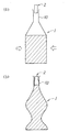
図1は、本発明の実施の形態における液体保存容器の構成例を示す図である。液体保存容器は、飲み残しのワインを保存するための容器であって、開口している首部(注ぎ口)10を有し、且つ首部10の下部が容積可変に変形可能な容器本体1と、その首部10に挿入されて、首部10を密閉する栓2とを備えて構成される。なお、図1(a)は、容器本体1が収縮されておらず、且つ栓2は首部10に挿入されていない状態を示し、図1(b)は容器本体1が収縮され、且つ栓2は首部10を密閉している状態を示す。
FIG. 1 is a diagram illustrating a configuration example of a liquid storage container according to an embodiment of the present invention. The liquid storage container is a container for storing wine left over, and has a neck portion (pour spout) 10 that is open, and the lower portion of the
容器本体1の形状は、図示されるように、フラスコ状であってもよいし、またワインボトルのような形状であってもよく、その形状は問わない。また、首部10は、円筒形状であり、好ましくは、所定長にわたって一定内径を有する。ただし、首部10の開口部分を末広がり形状とすることで、飲み残しのワインを容器内に移す作業を容易にし、容器内のワインを注ぎやすくすることができる。また、首部10は、容器本体1に対して取りはずし可能に取り付けられていてもよい(例えばネジ式)。もちろん、取り付けられている状態では、首部10は、容器本体1に密着している。
The shape of the
容器本体1は、ポリエチレン(PE)フィルム等を積層したオレフィン積層材料で形成され、好ましくは、容器本体1からの酸素透過を防止するために、非通気性プラスチック(例えばエチレン―ビニルアルコール共重合樹脂(EVOH))層を挟んでいる(例えば、市販のマヨネーズやケチャップの容器)。容器本体1は、その柔軟性(軟質性)により、手で押したり握る程度の外部からの力により、その形状を自在に変形させることができ、容器本体1を凹ませるように変形することで、容器本体1の容積は縮小される。なお、容器本体1は、変形可能な程度であるが且つ自立可能な程度の硬さを有し、特に、容器本体1における首部10の部分は、後述するように、栓2による密閉が可能な程度の剛性(硬質性)を有する。既知のブロー成形により、硬さが部位により異なる部材を一体的に成形することができる。また、容器本体1は、液面位置を視認可能とするために、透明であることが好ましいが、液面位置を視認可能な程度に色づけされていてもよい。
The
図1(b)に示すように、手で握るようにして容器本体1を変形させることで、容積を縮小させ、容器本体1内のワインの液面位置を自在に調整可能となり、その液面位置が首部10にまで達するように容器本体1を収縮させる。この状態で、栓2を首部10内の液面位置まで挿入し、栓2の底部が液面と接触する位置で首部10を密閉するように栓2は固定される。
As shown in FIG. 1B, by deforming the
栓2が液面に接触して首部10は密閉されるので、容器内の空気空間をなくすことができ、ワインは酸素に触れることなく保存することができる。
Since the
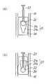
図2は、栓2の原理的な構成の断面図である。例えば、ワインボトルのコルク栓のように、ワインボトルの内径よりわずかに広くその弾力性及び復元性を利用してボトルの開口部に強制的に挿入して密閉する場合、容器内の空気を外部に排出できないため、液面位置に接するように、ワインボトルを密閉することができず、密閉状態において必ず容器内に空気空間が残る。
FIG. 2 is a cross-sectional view of the principle configuration of the
これに対して、本実施の形態における栓2は、挿入される際に、首部10に残る空気を排出させながら、ワインの液面位置まで達し、その位置で容器本体1を密閉することができる。その原理的な構成は、図2(a)に示すように、栓2の円筒部20は、例えばシリコンゴムのような圧力により変形する材質で形成され、内部に空洞部分21を有する。空洞部分には、上下方向に移動可能な球形部材22を収容し、球形部材22には、栓2の上面部から突出する棒状部材23が連結している。円筒部23と棒状部材23が係合する部分はそれぞれねじ切り加工されており、人の手により棒状部材23を回転させることで、球形部材22を空洞部分21内で上下方向に動かすことができる。空洞部分21は、その内径が上下方向(高さ方向)において異なるように形成され、球形部材22の径(幅方向長さ)より広い部分21aと球形部材の径より狭い部分21bが形成される。図2の例では、内径が連続的に変化する構造となっている。
On the other hand, when the
従って、図2(b)に示すように、棒状部材23を回転させて下方向に動かし、球形部材22を、内径が球形部材22の径より広い空洞部分21aから狭い空洞部分21bに移動させると、球形部材22は、空洞部分21bの内面を押圧し、それにより、栓2の径が外方向に広げられる。
Therefore, as shown in FIG. 2B, when the rod-
栓2の径は、球形部材22が空洞部分21aにあるときは、容器本体1の内径より小さく、首部10と栓2との隙間から空気を外部に排出しながら、栓2は首部10内に挿入され、栓2の底部(下面部)が液面位置に接した位置で、棒状部材23を押し下げることで、栓2の径を拡大させ、空洞部分21内部から圧力を首部10の内面に与えることで、栓2を首部10に密着する。こうして、栓2は、液面位置に接した位置で容器本体1を密閉することで、容器本体1内の空気空間をなくして、容器本体1内のワインを保存することが可能となる。
球形部材22及び棒状部材23は金属、プラスチック、ガラスなどで形成され、好ましくは一体的に成型される。また、球形部材22に変わって、別の形状の押圧部材であってもよく、径差により空洞部分21を内部から押圧できる形状であれば、その形状は問わない。さらに、空洞部分21の内径は、図2に例示するように、下に向かって狭くする場合に限らず、上方向に向かって狭くする構造であってもよい。その場合、棒状部材23を下から上に上げる(球形部材22を下から上に移動させる)操作により、栓2の径を拡大させる。円筒部材20の肉厚、球形部材22の径などの各種寸法は、首部10に密着して密閉するのに必要な数値を適宜選択する。
The diameter of the
The
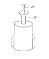
図3は、栓2の具体的な構成例を示す外観斜視図である。栓2の円筒部20の上面から棒状部材23が突出しており、円筒部20の上面には、持ち手24が取り付けられ、手で持ち手24を持って首部10内の円筒部20を液面位置に留めながら、棒状部材23を押し下げることで、円筒部20の径を拡大させ(点線部)、首部10に密着させる。
FIG. 3 is an external perspective view showing a specific configuration example of the
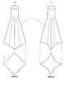
図4は、容器本体1の別の構成例を示す図である。図4には、容器本体1の外観形状と底面の形状が示される。容器本体1は、四角錐形状を基本形とし(図4(a))、その側面を内側に折り曲げるように凹ませることにより(図4(b))、底面積を小さくして容積を収縮させることで、ワインの液面位置を首部10まで押し上げることができる。
FIG. 4 is a diagram illustrating another configuration example of the
図5は、液体保存容器を支える支持具の例を示す図である。容器本体1の柔軟性により自立できない場合は、図5に示すように、支持具3の把持部30により、首部10のくびれ部分を把持し、吊り下げる。もちろん、容器本体1が自立可能に形成されている場合は、図5の支持具は必要ない。なお、図5では、栓2の記載を省略している。
FIG. 5 is a diagram illustrating an example of a support that supports the liquid storage container. If the
図6は、本発明の実施の形態における栓の別の構成例を示す図である。本例の栓5は、飲み残しのワインが入っている円筒形のワイン瓶40にそのまま適用するものであり、ワイン瓶40の首部41からその内部に挿入可能な棒状部材51の先端に、径が変化する径可変構造体52が固定されている。
FIG. 6 is a diagram showing another configuration example of the stopper according to the embodiment of the present invention. The
径可変構造体52は、棒状部材51のワイン瓶40内部の一端51aに固定され且つ径が変化する拡大収縮部521と、拡大収縮部521に接続して首部41から外部に延びるパイプ状の延長部522を備えて構成される。
The
延長部522は、例えばステンレスパイプで形成されるが、必要な強度が確保される他の素材でもかまわない。棒状部材51は延長部522内を通り、外部に突出している。
The
拡大収縮部521は、傘状の円錐形状を2つ合わせたような形状であり、傘の開閉動作のように上下動させることで、径が変化する。拡大収縮部521の径は首部41の内径より小さい径からワイン瓶40の少なくとも最大内径まで拡大可能であり、図示されるように、延長部522を固定したまま、棒状部材51を上に引き上げることで、拡大収縮部521は傘状に開き、その径が拡大し、その状態から下に押し下げることで、傘が閉じられるようにその径を収縮させることができる。拡大収縮部521は、例えば、ビニールやナイロンなどの水及び空気が浸透しない素材で形成され、拡大時にワイン瓶40の内面に密着する外縁部はシリコンゴムなどが取り付けられる。
The expansion /
好ましくは、栓5は、首部41に嵌合する円筒部53を有し、延長部522は円筒部53を貫通して外部に露出し、棒状部材の他端51bは、パイプ状の延長部522から外部に突出している。円筒部53は、延長部522を固定するのに有用である。また、円筒部53は、延長部522の長さ方向に対して移動可能であり、径可変構造体52をワイン瓶40内の所望の位置に位置決めすることができる。
Preferably, the
径可変構造体52の動作は以下の通りである。飲み残しのワインが残っているワイン瓶40内部に拡大収縮部521を閉じた状態で挿入し(図6(a))、外部に露出している棒状部材51の他端51b側を引き上げて、拡大収縮部522の径を拡大させ、その外縁522aをワイン瓶40の内面に密着させる。これにより、ワイン瓶40の断面が覆われ、ワインの液面付近を密閉することで、液面上の空気空間をほぼなくすことができ、ワインの酸化防止を抑制することができる。
The operation of the
また、図6に示した構造の栓5は、容積可変に変形可能な容器本体1(図1)の首部を密閉する栓としても適用可能である。すなわち、棒状部材51の一端が首部内に挿入され、径可変構造体52の拡大収縮部521は、首部の内径より小さい径から少なくとも首部の内径まで拡大可能とする。そして、延長部522を固定したまま、棒状部材51を上に引き上げることで、拡大収縮部521は傘状に開き、その径を拡大し、拡大収縮部521の外周部が首部の内周面に密着することで、首部の任意の位置を密閉することができる。
Moreover, the
棒状部材51と延長部材522とを螺合させ、棒状部材51を回転させることで、延長部材522に対して上下方向に移動させ、拡大収縮部521の径を変化させるようにしてもよい。また、ワイン瓶に限らず、他の液体保存用容器にも適用可能である。
上述の実施の形態例では、ワインの保存容器として説明したが、本実施の形態例の液体保存容器は、ワインに限らず、空気(酸素)との接触により劣化する他の液体の保存にも適用される。
The rod-shaped
In the above-described embodiment, the wine storage container has been described. However, the liquid storage container according to the present embodiment is not limited to wine, and can store other liquids that deteriorate due to contact with air (oxygen). Applied.
1:容器本体、2:栓、3:支持具、10:首部、20:円筒部、21:空洞部分、22:球形部材、23:棒状部材、24:持ち手、30:把持部、40:ワイン瓶、41:首部、51:棒状部材、52:径可変構造体、521:拡大収縮部、522:延長部材、53:円筒部 1: container body, 2: stopper, 3: support, 10: neck, 20: cylindrical part, 21: hollow part, 22: spherical member, 23: rod-like member, 24: handle, 30: gripping part, 40: Wine bottle, 41: neck, 51: rod-like member, 52: variable diameter structure, 521: expansion / contraction part, 522: extension member, 53: cylindrical part
Claims (7)
前記首部の内径よりも小さい口径から前記首部の内径より大きい口径まで径を拡大させることができる栓とを備え、
前記栓が前記首部の内径よりも小さい口径の状態で前記首部の開口部分から前記首部に挿入され、前記栓を前記首部の内面に密着させるように前記首部内で前記栓の径を拡大させることで、前記首部の任意の位置で前記首部を密閉することを特徴とする液体保存容器。 A container body having a neck of a predetermined length that is open and deformable in a variable volume;
A stopper capable of expanding the diameter from a smaller diameter than the inner diameter of the neck to a larger diameter than the inner diameter of the neck,
The plug is inserted into the neck from the opening of the neck in a state where the diameter is smaller than the inner diameter of the neck, and the diameter of the plug is enlarged in the neck so that the plug is in close contact with the inner surface of the neck. The liquid storage container is characterized in that the neck is sealed at an arbitrary position of the neck.
前記栓は、内部の空洞に収容された押圧部材の移動により、前記栓の側面を空洞内から押圧することで、前記栓の径を拡大させることを特徴とする液体保存容器。 In claim 1,
The liquid storage container, wherein the stopper expands the diameter of the stopper by pressing a side surface of the stopper from the inside of the cavity by movement of a pressing member accommodated in the cavity.
前記首部の開口部分は末広がり形状であることを特徴とする液体保存容器。 In claim 1 or 2,
The liquid storage container, wherein the opening of the neck has a divergent shape.
前記空洞部分に移動可能に収容される押圧部材と、
前記押圧部材に連結し、前記円筒部材の上面から突出する棒状部材とを備え、
前記空洞部分には、前記押圧部材の幅方向長さより広い内径部分と前記押圧部材の幅方向長さより短い内径が形成されていることを特徴とする液体保存容器用栓。 A cylindrical member having a hollow portion therein;
A pressing member movably accommodated in the hollow portion;
A rod-shaped member connected to the pressing member and protruding from the upper surface of the cylindrical member;
A stopper for a liquid storage container, wherein an inner diameter portion wider than a width direction length of the pressing member and an inner diameter shorter than a width direction length of the pressing member are formed in the hollow portion.
前記容器よりも長く、前記首部から前記容器内部に挿入可能な棒状部材と、
前記棒状部材の前記容器内部側の一端に固定され、前記容器内部で前記首部の内径よりも小さい状態から少なくとも前記容器の最大内径まで変化し、前記容器の断面を覆う径可変構造体とを備えることを特徴とする栓。 In a closure for closing a cylindrical container with an open neck,
A rod-like member that is longer than the container and is insertable from the neck into the container;
A variable diameter structure that is fixed to one end of the rod-shaped member on the container inner side, changes from a state smaller than the inner diameter of the neck portion to at least the maximum inner diameter of the container, and covers a cross section of the container. A plug characterized by that.
前記首部に挿入可能な棒状部材と、
前記棒状部材の前記首部内側の一端に固定され、前記首部の内径よりも小さい状態から少なくとも前記首部の最大内径まで変化し、前記首部の断面を覆う径可変構造体とを備えることを特徴とする栓。 In a closure for closing a cylindrical container with an open neck,
A rod-like member insertable into the neck,
The rod-shaped member is fixed to one end inside the neck portion, and has a variable diameter structure that changes from a state smaller than the inner diameter of the neck portion to at least the maximum inner diameter of the neck portion and covers a cross section of the neck portion. plug.
前記径可変構造体に対して前記棒状部材をその長さ方向に相対的に移動させることで、前記可変構造体の径を変化させることを特徴とする栓。 In claim 5 or 6,
A plug, wherein the diameter of the variable structure is changed by moving the rod-shaped member relative to the variable diameter structure in the length direction.
Priority Applications (1)
| Application Number | Priority Date | Filing Date | Title |
|---|---|---|---|
| JP2008274380A JP4267060B1 (en) | 2008-10-24 | 2008-10-24 | Liquid storage container |
Applications Claiming Priority (1)
| Application Number | Priority Date | Filing Date | Title |
|---|---|---|---|
| JP2008274380A JP4267060B1 (en) | 2008-10-24 | 2008-10-24 | Liquid storage container |
Publications (2)
| Publication Number | Publication Date |
|---|---|
| JP4267060B1 JP4267060B1 (en) | 2009-05-27 |
| JP2010100320A true JP2010100320A (en) | 2010-05-06 |
Family
ID=40785237
Family Applications (1)
| Application Number | Title | Priority Date | Filing Date |
|---|---|---|---|
| JP2008274380A Active JP4267060B1 (en) | 2008-10-24 | 2008-10-24 | Liquid storage container |
Country Status (1)
| Country | Link |
|---|---|
| JP (1) | JP4267060B1 (en) |
Citations (11)
| Publication number | Priority date | Publication date | Assignee | Title |
|---|---|---|---|---|
| JPS52152058U (en) * | 1976-05-11 | 1977-11-17 | ||
| JPS5746758A (en) * | 1980-08-25 | 1982-03-17 | Zaibun Boku | Plug body |
| JPS58171852U (en) * | 1982-05-11 | 1983-11-16 | 本谷 富夫 | bottle stopper |
| JPH01141243U (en) * | 1988-03-24 | 1989-09-27 | ||
| JPH0257567A (en) * | 1988-08-10 | 1990-02-27 | Taiun Hojo | Stable liquid discharger |
| JP3023855U (en) * | 1995-10-17 | 1996-04-30 | 直記 安村 | Jar stopper |
| JPH08151060A (en) * | 1994-11-24 | 1996-06-11 | Yamamura Glass Co Ltd | Cock of bottle |
| JP3043027U (en) * | 1997-05-01 | 1997-11-11 | エーディープラント株式会社 | Air shutoff container |
| JPH10297634A (en) * | 1997-04-25 | 1998-11-10 | Ee D Plant Kk | Air blocking container |
| JP2002053138A (en) * | 2001-07-02 | 2002-02-19 | Tadashi Hagiwara | Self-supporting container |
| JP2006036277A (en) * | 2004-07-27 | 2006-02-09 | Tomomi Sekihara | Device for preventing degradation of liquid remaining in bottle and method of using it |
-
2008
- 2008-10-24 JP JP2008274380A patent/JP4267060B1/en active Active
Patent Citations (11)
| Publication number | Priority date | Publication date | Assignee | Title |
|---|---|---|---|---|
| JPS52152058U (en) * | 1976-05-11 | 1977-11-17 | ||
| JPS5746758A (en) * | 1980-08-25 | 1982-03-17 | Zaibun Boku | Plug body |
| JPS58171852U (en) * | 1982-05-11 | 1983-11-16 | 本谷 富夫 | bottle stopper |
| JPH01141243U (en) * | 1988-03-24 | 1989-09-27 | ||
| JPH0257567A (en) * | 1988-08-10 | 1990-02-27 | Taiun Hojo | Stable liquid discharger |
| JPH08151060A (en) * | 1994-11-24 | 1996-06-11 | Yamamura Glass Co Ltd | Cock of bottle |
| JP3023855U (en) * | 1995-10-17 | 1996-04-30 | 直記 安村 | Jar stopper |
| JPH10297634A (en) * | 1997-04-25 | 1998-11-10 | Ee D Plant Kk | Air blocking container |
| JP3043027U (en) * | 1997-05-01 | 1997-11-11 | エーディープラント株式会社 | Air shutoff container |
| JP2002053138A (en) * | 2001-07-02 | 2002-02-19 | Tadashi Hagiwara | Self-supporting container |
| JP2006036277A (en) * | 2004-07-27 | 2006-02-09 | Tomomi Sekihara | Device for preventing degradation of liquid remaining in bottle and method of using it |
Also Published As
| Publication number | Publication date |
|---|---|
| JP4267060B1 (en) | 2009-05-27 |
Similar Documents
| Publication | Publication Date | Title |
|---|---|---|
| JP4452475B2 (en) | Plastic bottle | |
| US20080023434A1 (en) | Method and Apparatus for a Removable Handle for a Bottle | |
| JP5356216B2 (en) | Storage and drinking containers | |
| JP2006518694A (en) | Beverage squeeze bottle | |
| CN104159477A (en) | A container for drinking drinks. | |
| US20110220606A1 (en) | Container stoppers | |
| JP2011098780A (en) | Container bottle structure responsive to vacuum related force | |
| US9290295B2 (en) | Resealable decanter with evacuation system | |
| US20070272698A1 (en) | An Improved Container | |
| AU2011226826B2 (en) | A resealable decanter with evacuation system | |
| JP2013147284A (en) | Variable capacity container | |
| AU2008323322B2 (en) | Dispensing device | |
| CA2854401C (en) | Bottle including a hollow removable closure | |
| JP4267060B1 (en) | Liquid storage container | |
| JP5463645B2 (en) | Pouch container | |
| US20110163094A1 (en) | Fluid preservation system and method for use | |
| JP6739877B2 (en) | Container with cap | |
| WO2017014638A1 (en) | Liquid preservation device and method | |
| EP2128039B1 (en) | Beverage container equipped with straw | |
| JP6547267B2 (en) | Mouthpiece | |
| JP2006103794A (en) | Cap and beverage-container closure | |
| JP5014505B1 (en) | Method of storing liquid using container storage lid | |
| JP5723506B2 (en) | container | |
| KR102546106B1 (en) | bottle with dropper | |
| US20100270321A1 (en) | Beverage container equipped with with straw |
Legal Events
| Date | Code | Title | Description |
|---|---|---|---|
| TRDD | Decision of grant or rejection written | ||
| A01 | Written decision to grant a patent or to grant a registration (utility model) |
Free format text: JAPANESE INTERMEDIATE CODE: A01 Effective date: 20090217 |
|
| A01 | Written decision to grant a patent or to grant a registration (utility model) |
Free format text: JAPANESE INTERMEDIATE CODE: A01 |
|
| A61 | First payment of annual fees (during grant procedure) |
Free format text: JAPANESE INTERMEDIATE CODE: A61 Effective date: 20090217 |
|
| R150 | Certificate of patent or registration of utility model |
Ref document number: 4267060 Country of ref document: JP Free format text: JAPANESE INTERMEDIATE CODE: R150 Free format text: JAPANESE INTERMEDIATE CODE: R150 |
|
| FPAY | Renewal fee payment (event date is renewal date of database) |
Free format text: PAYMENT UNTIL: 20120227 Year of fee payment: 3 |
|
| FPAY | Renewal fee payment (event date is renewal date of database) |
Free format text: PAYMENT UNTIL: 20150227 Year of fee payment: 6 |
|
| R250 | Receipt of annual fees |
Free format text: JAPANESE INTERMEDIATE CODE: R250 |
|
| R250 | Receipt of annual fees |
Free format text: JAPANESE INTERMEDIATE CODE: R250 |
|
| R250 | Receipt of annual fees |
Free format text: JAPANESE INTERMEDIATE CODE: R250 |
|
| R250 | Receipt of annual fees |
Free format text: JAPANESE INTERMEDIATE CODE: R250 |
|
| R250 | Receipt of annual fees |
Free format text: JAPANESE INTERMEDIATE CODE: R250 |
|
| R250 | Receipt of annual fees |
Free format text: JAPANESE INTERMEDIATE CODE: R250 |
|
| R250 | Receipt of annual fees |
Free format text: JAPANESE INTERMEDIATE CODE: R250 |
|
| R250 | Receipt of annual fees |
Free format text: JAPANESE INTERMEDIATE CODE: R250 |
|
| R250 | Receipt of annual fees |
Free format text: JAPANESE INTERMEDIATE CODE: R250 |
|
| R250 | Receipt of annual fees |
Free format text: JAPANESE INTERMEDIATE CODE: R250 |