JP2010100216A - Drive unit of vehicle - Google Patents
Drive unit of vehicle Download PDFInfo
- Publication number
- JP2010100216A JP2010100216A JP2008274586A JP2008274586A JP2010100216A JP 2010100216 A JP2010100216 A JP 2010100216A JP 2008274586 A JP2008274586 A JP 2008274586A JP 2008274586 A JP2008274586 A JP 2008274586A JP 2010100216 A JP2010100216 A JP 2010100216A
- Authority
- JP
- Japan
- Prior art keywords
- gear
- support wall
- brake
- clutch
- electric motor
- Prior art date
- Legal status (The legal status is an assumption and is not a legal conclusion. Google has not performed a legal analysis and makes no representation as to the accuracy of the status listed.)
- Granted
Links
Images


Classifications
-
- B—PERFORMING OPERATIONS; TRANSPORTING
- B60—VEHICLES IN GENERAL
- B60K—ARRANGEMENT OR MOUNTING OF PROPULSION UNITS OR OF TRANSMISSIONS IN VEHICLES; ARRANGEMENT OR MOUNTING OF PLURAL DIVERSE PRIME-MOVERS IN VEHICLES; AUXILIARY DRIVES FOR VEHICLES; INSTRUMENTATION OR DASHBOARDS FOR VEHICLES; ARRANGEMENTS IN CONNECTION WITH COOLING, AIR INTAKE, GAS EXHAUST OR FUEL SUPPLY OF PROPULSION UNITS IN VEHICLES
- B60K6/00—Arrangement or mounting of plural diverse prime-movers for mutual or common propulsion, e.g. hybrid propulsion systems comprising electric motors and internal combustion engines ; Control systems therefor, i.e. systems controlling two or more prime movers, or controlling one of these prime movers and any of the transmission, drive or drive units Informative references: mechanical gearings with secondary electric drive F16H3/72; arrangements for handling mechanical energy structurally associated with the dynamo-electric machine H02K7/00; machines comprising structurally interrelated motor and generator parts H02K51/00; dynamo-electric machines not otherwise provided for in H02K see H02K99/00
- B60K6/20—Arrangement or mounting of plural diverse prime-movers for mutual or common propulsion, e.g. hybrid propulsion systems comprising electric motors and internal combustion engines ; Control systems therefor, i.e. systems controlling two or more prime movers, or controlling one of these prime movers and any of the transmission, drive or drive units Informative references: mechanical gearings with secondary electric drive F16H3/72; arrangements for handling mechanical energy structurally associated with the dynamo-electric machine H02K7/00; machines comprising structurally interrelated motor and generator parts H02K51/00; dynamo-electric machines not otherwise provided for in H02K see H02K99/00 the prime-movers consisting of electric motors and internal combustion engines, e.g. HEVs
- B60K6/22—Arrangement or mounting of plural diverse prime-movers for mutual or common propulsion, e.g. hybrid propulsion systems comprising electric motors and internal combustion engines ; Control systems therefor, i.e. systems controlling two or more prime movers, or controlling one of these prime movers and any of the transmission, drive or drive units Informative references: mechanical gearings with secondary electric drive F16H3/72; arrangements for handling mechanical energy structurally associated with the dynamo-electric machine H02K7/00; machines comprising structurally interrelated motor and generator parts H02K51/00; dynamo-electric machines not otherwise provided for in H02K see H02K99/00 the prime-movers consisting of electric motors and internal combustion engines, e.g. HEVs characterised by apparatus, components or means specially adapted for HEVs
- B60K6/40—Arrangement or mounting of plural diverse prime-movers for mutual or common propulsion, e.g. hybrid propulsion systems comprising electric motors and internal combustion engines ; Control systems therefor, i.e. systems controlling two or more prime movers, or controlling one of these prime movers and any of the transmission, drive or drive units Informative references: mechanical gearings with secondary electric drive F16H3/72; arrangements for handling mechanical energy structurally associated with the dynamo-electric machine H02K7/00; machines comprising structurally interrelated motor and generator parts H02K51/00; dynamo-electric machines not otherwise provided for in H02K see H02K99/00 the prime-movers consisting of electric motors and internal combustion engines, e.g. HEVs characterised by apparatus, components or means specially adapted for HEVs characterised by the assembly or relative disposition of components
- B60K6/405—Housings
-
- B—PERFORMING OPERATIONS; TRANSPORTING
- B60—VEHICLES IN GENERAL
- B60K—ARRANGEMENT OR MOUNTING OF PROPULSION UNITS OR OF TRANSMISSIONS IN VEHICLES; ARRANGEMENT OR MOUNTING OF PLURAL DIVERSE PRIME-MOVERS IN VEHICLES; AUXILIARY DRIVES FOR VEHICLES; INSTRUMENTATION OR DASHBOARDS FOR VEHICLES; ARRANGEMENTS IN CONNECTION WITH COOLING, AIR INTAKE, GAS EXHAUST OR FUEL SUPPLY OF PROPULSION UNITS IN VEHICLES
- B60K6/00—Arrangement or mounting of plural diverse prime-movers for mutual or common propulsion, e.g. hybrid propulsion systems comprising electric motors and internal combustion engines ; Control systems therefor, i.e. systems controlling two or more prime movers, or controlling one of these prime movers and any of the transmission, drive or drive units Informative references: mechanical gearings with secondary electric drive F16H3/72; arrangements for handling mechanical energy structurally associated with the dynamo-electric machine H02K7/00; machines comprising structurally interrelated motor and generator parts H02K51/00; dynamo-electric machines not otherwise provided for in H02K see H02K99/00
- B60K6/20—Arrangement or mounting of plural diverse prime-movers for mutual or common propulsion, e.g. hybrid propulsion systems comprising electric motors and internal combustion engines ; Control systems therefor, i.e. systems controlling two or more prime movers, or controlling one of these prime movers and any of the transmission, drive or drive units Informative references: mechanical gearings with secondary electric drive F16H3/72; arrangements for handling mechanical energy structurally associated with the dynamo-electric machine H02K7/00; machines comprising structurally interrelated motor and generator parts H02K51/00; dynamo-electric machines not otherwise provided for in H02K see H02K99/00 the prime-movers consisting of electric motors and internal combustion engines, e.g. HEVs
- B60K6/42—Arrangement or mounting of plural diverse prime-movers for mutual or common propulsion, e.g. hybrid propulsion systems comprising electric motors and internal combustion engines ; Control systems therefor, i.e. systems controlling two or more prime movers, or controlling one of these prime movers and any of the transmission, drive or drive units Informative references: mechanical gearings with secondary electric drive F16H3/72; arrangements for handling mechanical energy structurally associated with the dynamo-electric machine H02K7/00; machines comprising structurally interrelated motor and generator parts H02K51/00; dynamo-electric machines not otherwise provided for in H02K see H02K99/00 the prime-movers consisting of electric motors and internal combustion engines, e.g. HEVs characterised by the architecture of the hybrid electric vehicle
- B60K6/44—Series-parallel type
- B60K6/445—Differential gearing distribution type
-
- B—PERFORMING OPERATIONS; TRANSPORTING
- B60—VEHICLES IN GENERAL
- B60L—PROPULSION OF ELECTRICALLY-PROPELLED VEHICLES; SUPPLYING ELECTRIC POWER FOR AUXILIARY EQUIPMENT OF ELECTRICALLY-PROPELLED VEHICLES; ELECTRODYNAMIC BRAKE SYSTEMS FOR VEHICLES IN GENERAL; MAGNETIC SUSPENSION OR LEVITATION FOR VEHICLES; MONITORING OPERATING VARIABLES OF ELECTRICALLY-PROPELLED VEHICLES; ELECTRIC SAFETY DEVICES FOR ELECTRICALLY-PROPELLED VEHICLES
- B60L15/00—Methods, circuits, or devices for controlling the traction-motor speed of electrically-propelled vehicles
- B60L15/20—Methods, circuits, or devices for controlling the traction-motor speed of electrically-propelled vehicles for control of the vehicle or its driving motor to achieve a desired performance, e.g. speed, torque, programmed variation of speed
- B60L15/2054—Methods, circuits, or devices for controlling the traction-motor speed of electrically-propelled vehicles for control of the vehicle or its driving motor to achieve a desired performance, e.g. speed, torque, programmed variation of speed by controlling transmissions or clutches
-
- B—PERFORMING OPERATIONS; TRANSPORTING
- B60—VEHICLES IN GENERAL
- B60L—PROPULSION OF ELECTRICALLY-PROPELLED VEHICLES; SUPPLYING ELECTRIC POWER FOR AUXILIARY EQUIPMENT OF ELECTRICALLY-PROPELLED VEHICLES; ELECTRODYNAMIC BRAKE SYSTEMS FOR VEHICLES IN GENERAL; MAGNETIC SUSPENSION OR LEVITATION FOR VEHICLES; MONITORING OPERATING VARIABLES OF ELECTRICALLY-PROPELLED VEHICLES; ELECTRIC SAFETY DEVICES FOR ELECTRICALLY-PROPELLED VEHICLES
- B60L3/00—Electric devices on electrically-propelled vehicles for safety purposes; Monitoring operating variables, e.g. speed, deceleration or energy consumption
- B60L3/0023—Detecting, eliminating, remedying or compensating for drive train abnormalities, e.g. failures within the drive train
- B60L3/0061—Detecting, eliminating, remedying or compensating for drive train abnormalities, e.g. failures within the drive train relating to electrical machines
-
- B—PERFORMING OPERATIONS; TRANSPORTING
- B60—VEHICLES IN GENERAL
- B60L—PROPULSION OF ELECTRICALLY-PROPELLED VEHICLES; SUPPLYING ELECTRIC POWER FOR AUXILIARY EQUIPMENT OF ELECTRICALLY-PROPELLED VEHICLES; ELECTRODYNAMIC BRAKE SYSTEMS FOR VEHICLES IN GENERAL; MAGNETIC SUSPENSION OR LEVITATION FOR VEHICLES; MONITORING OPERATING VARIABLES OF ELECTRICALLY-PROPELLED VEHICLES; ELECTRIC SAFETY DEVICES FOR ELECTRICALLY-PROPELLED VEHICLES
- B60L50/00—Electric propulsion with power supplied within the vehicle
- B60L50/10—Electric propulsion with power supplied within the vehicle using propulsion power supplied by engine-driven generators, e.g. generators driven by combustion engines
- B60L50/16—Electric propulsion with power supplied within the vehicle using propulsion power supplied by engine-driven generators, e.g. generators driven by combustion engines with provision for separate direct mechanical propulsion
-
- B—PERFORMING OPERATIONS; TRANSPORTING
- B60—VEHICLES IN GENERAL
- B60L—PROPULSION OF ELECTRICALLY-PROPELLED VEHICLES; SUPPLYING ELECTRIC POWER FOR AUXILIARY EQUIPMENT OF ELECTRICALLY-PROPELLED VEHICLES; ELECTRODYNAMIC BRAKE SYSTEMS FOR VEHICLES IN GENERAL; MAGNETIC SUSPENSION OR LEVITATION FOR VEHICLES; MONITORING OPERATING VARIABLES OF ELECTRICALLY-PROPELLED VEHICLES; ELECTRIC SAFETY DEVICES FOR ELECTRICALLY-PROPELLED VEHICLES
- B60L50/00—Electric propulsion with power supplied within the vehicle
- B60L50/50—Electric propulsion with power supplied within the vehicle using propulsion power supplied by batteries or fuel cells
- B60L50/60—Electric propulsion with power supplied within the vehicle using propulsion power supplied by batteries or fuel cells using power supplied by batteries
- B60L50/61—Electric propulsion with power supplied within the vehicle using propulsion power supplied by batteries or fuel cells using power supplied by batteries by batteries charged by engine-driven generators, e.g. series hybrid electric vehicles
-
- F—MECHANICAL ENGINEERING; LIGHTING; HEATING; WEAPONS; BLASTING
- F16—ENGINEERING ELEMENTS AND UNITS; GENERAL MEASURES FOR PRODUCING AND MAINTAINING EFFECTIVE FUNCTIONING OF MACHINES OR INSTALLATIONS; THERMAL INSULATION IN GENERAL
- F16H—GEARING
- F16H3/00—Toothed gearings for conveying rotary motion with variable gear ratio or for reversing rotary motion
- F16H3/44—Toothed gearings for conveying rotary motion with variable gear ratio or for reversing rotary motion using gears having orbital motion
- F16H3/72—Toothed gearings for conveying rotary motion with variable gear ratio or for reversing rotary motion using gears having orbital motion with a secondary drive, e.g. regulating motor, in order to vary speed continuously
- F16H3/727—Toothed gearings for conveying rotary motion with variable gear ratio or for reversing rotary motion using gears having orbital motion with a secondary drive, e.g. regulating motor, in order to vary speed continuously with at least two dynamo electric machines for creating an electric power path inside the gearing, e.g. using generator and motor for a variable power torque path
- F16H3/728—Toothed gearings for conveying rotary motion with variable gear ratio or for reversing rotary motion using gears having orbital motion with a secondary drive, e.g. regulating motor, in order to vary speed continuously with at least two dynamo electric machines for creating an electric power path inside the gearing, e.g. using generator and motor for a variable power torque path with means to change ratio in the mechanical gearing
-
- B—PERFORMING OPERATIONS; TRANSPORTING
- B60—VEHICLES IN GENERAL
- B60L—PROPULSION OF ELECTRICALLY-PROPELLED VEHICLES; SUPPLYING ELECTRIC POWER FOR AUXILIARY EQUIPMENT OF ELECTRICALLY-PROPELLED VEHICLES; ELECTRODYNAMIC BRAKE SYSTEMS FOR VEHICLES IN GENERAL; MAGNETIC SUSPENSION OR LEVITATION FOR VEHICLES; MONITORING OPERATING VARIABLES OF ELECTRICALLY-PROPELLED VEHICLES; ELECTRIC SAFETY DEVICES FOR ELECTRICALLY-PROPELLED VEHICLES
- B60L2240/00—Control parameters of input or output; Target parameters
- B60L2240/40—Drive Train control parameters
- B60L2240/42—Drive Train control parameters related to electric machines
- B60L2240/421—Speed
-
- B—PERFORMING OPERATIONS; TRANSPORTING
- B60—VEHICLES IN GENERAL
- B60L—PROPULSION OF ELECTRICALLY-PROPELLED VEHICLES; SUPPLYING ELECTRIC POWER FOR AUXILIARY EQUIPMENT OF ELECTRICALLY-PROPELLED VEHICLES; ELECTRODYNAMIC BRAKE SYSTEMS FOR VEHICLES IN GENERAL; MAGNETIC SUSPENSION OR LEVITATION FOR VEHICLES; MONITORING OPERATING VARIABLES OF ELECTRICALLY-PROPELLED VEHICLES; ELECTRIC SAFETY DEVICES FOR ELECTRICALLY-PROPELLED VEHICLES
- B60L2240/00—Control parameters of input or output; Target parameters
- B60L2240/40—Drive Train control parameters
- B60L2240/42—Drive Train control parameters related to electric machines
- B60L2240/425—Temperature
-
- B—PERFORMING OPERATIONS; TRANSPORTING
- B60—VEHICLES IN GENERAL
- B60L—PROPULSION OF ELECTRICALLY-PROPELLED VEHICLES; SUPPLYING ELECTRIC POWER FOR AUXILIARY EQUIPMENT OF ELECTRICALLY-PROPELLED VEHICLES; ELECTRODYNAMIC BRAKE SYSTEMS FOR VEHICLES IN GENERAL; MAGNETIC SUSPENSION OR LEVITATION FOR VEHICLES; MONITORING OPERATING VARIABLES OF ELECTRICALLY-PROPELLED VEHICLES; ELECTRIC SAFETY DEVICES FOR ELECTRICALLY-PROPELLED VEHICLES
- B60L2240/00—Control parameters of input or output; Target parameters
- B60L2240/40—Drive Train control parameters
- B60L2240/44—Drive Train control parameters related to combustion engines
- B60L2240/441—Speed
-
- B—PERFORMING OPERATIONS; TRANSPORTING
- B60—VEHICLES IN GENERAL
- B60L—PROPULSION OF ELECTRICALLY-PROPELLED VEHICLES; SUPPLYING ELECTRIC POWER FOR AUXILIARY EQUIPMENT OF ELECTRICALLY-PROPELLED VEHICLES; ELECTRODYNAMIC BRAKE SYSTEMS FOR VEHICLES IN GENERAL; MAGNETIC SUSPENSION OR LEVITATION FOR VEHICLES; MONITORING OPERATING VARIABLES OF ELECTRICALLY-PROPELLED VEHICLES; ELECTRIC SAFETY DEVICES FOR ELECTRICALLY-PROPELLED VEHICLES
- B60L2240/00—Control parameters of input or output; Target parameters
- B60L2240/40—Drive Train control parameters
- B60L2240/48—Drive Train control parameters related to transmissions
- B60L2240/486—Operating parameters
-
- B—PERFORMING OPERATIONS; TRANSPORTING
- B60—VEHICLES IN GENERAL
- B60L—PROPULSION OF ELECTRICALLY-PROPELLED VEHICLES; SUPPLYING ELECTRIC POWER FOR AUXILIARY EQUIPMENT OF ELECTRICALLY-PROPELLED VEHICLES; ELECTRODYNAMIC BRAKE SYSTEMS FOR VEHICLES IN GENERAL; MAGNETIC SUSPENSION OR LEVITATION FOR VEHICLES; MONITORING OPERATING VARIABLES OF ELECTRICALLY-PROPELLED VEHICLES; ELECTRIC SAFETY DEVICES FOR ELECTRICALLY-PROPELLED VEHICLES
- B60L2240/00—Control parameters of input or output; Target parameters
- B60L2240/40—Drive Train control parameters
- B60L2240/50—Drive Train control parameters related to clutches
- B60L2240/507—Operating parameters
-
- F—MECHANICAL ENGINEERING; LIGHTING; HEATING; WEAPONS; BLASTING
- F16—ENGINEERING ELEMENTS AND UNITS; GENERAL MEASURES FOR PRODUCING AND MAINTAINING EFFECTIVE FUNCTIONING OF MACHINES OR INSTALLATIONS; THERMAL INSULATION IN GENERAL
- F16H—GEARING
- F16H37/00—Combinations of mechanical gearings, not provided for in groups F16H1/00 - F16H35/00
- F16H37/02—Combinations of mechanical gearings, not provided for in groups F16H1/00 - F16H35/00 comprising essentially only toothed or friction gearings
- F16H37/06—Combinations of mechanical gearings, not provided for in groups F16H1/00 - F16H35/00 comprising essentially only toothed or friction gearings with a plurality of driving or driven shafts; with arrangements for dividing torque between two or more intermediate shafts
- F16H37/08—Combinations of mechanical gearings, not provided for in groups F16H1/00 - F16H35/00 comprising essentially only toothed or friction gearings with a plurality of driving or driven shafts; with arrangements for dividing torque between two or more intermediate shafts with differential gearing
- F16H37/0833—Combinations of mechanical gearings, not provided for in groups F16H1/00 - F16H35/00 comprising essentially only toothed or friction gearings with a plurality of driving or driven shafts; with arrangements for dividing torque between two or more intermediate shafts with differential gearing with arrangements for dividing torque between two or more intermediate shafts, i.e. with two or more internal power paths
- F16H37/084—Combinations of mechanical gearings, not provided for in groups F16H1/00 - F16H35/00 comprising essentially only toothed or friction gearings with a plurality of driving or driven shafts; with arrangements for dividing torque between two or more intermediate shafts with differential gearing with arrangements for dividing torque between two or more intermediate shafts, i.e. with two or more internal power paths at least one power path being a continuously variable transmission, i.e. CVT
- F16H2037/0866—Power split variators with distributing differentials, with the output of the CVT connected or connectable to the output shaft
- F16H2037/0873—Power split variators with distributing differentials, with the output of the CVT connected or connectable to the output shaft with switching, e.g. to change ranges
-
- F—MECHANICAL ENGINEERING; LIGHTING; HEATING; WEAPONS; BLASTING
- F16—ENGINEERING ELEMENTS AND UNITS; GENERAL MEASURES FOR PRODUCING AND MAINTAINING EFFECTIVE FUNCTIONING OF MACHINES OR INSTALLATIONS; THERMAL INSULATION IN GENERAL
- F16H—GEARING
- F16H2200/00—Transmissions for multiple ratios
- F16H2200/20—Transmissions using gears with orbital motion
- F16H2200/2002—Transmissions using gears with orbital motion characterised by the number of sets of orbital gears
- F16H2200/2007—Transmissions using gears with orbital motion characterised by the number of sets of orbital gears with two sets of orbital gears
-
- F—MECHANICAL ENGINEERING; LIGHTING; HEATING; WEAPONS; BLASTING
- F16—ENGINEERING ELEMENTS AND UNITS; GENERAL MEASURES FOR PRODUCING AND MAINTAINING EFFECTIVE FUNCTIONING OF MACHINES OR INSTALLATIONS; THERMAL INSULATION IN GENERAL
- F16H—GEARING
- F16H2200/00—Transmissions for multiple ratios
- F16H2200/20—Transmissions using gears with orbital motion
- F16H2200/203—Transmissions using gears with orbital motion characterised by the engaging friction means not of the freewheel type, e.g. friction clutches or brakes
- F16H2200/2035—Transmissions using gears with orbital motion characterised by the engaging friction means not of the freewheel type, e.g. friction clutches or brakes with two engaging means
-
- F—MECHANICAL ENGINEERING; LIGHTING; HEATING; WEAPONS; BLASTING
- F16—ENGINEERING ELEMENTS AND UNITS; GENERAL MEASURES FOR PRODUCING AND MAINTAINING EFFECTIVE FUNCTIONING OF MACHINES OR INSTALLATIONS; THERMAL INSULATION IN GENERAL
- F16H—GEARING
- F16H2200/00—Transmissions for multiple ratios
- F16H2200/20—Transmissions using gears with orbital motion
- F16H2200/2097—Transmissions using gears with orbital motion comprising an orbital gear set member permanently connected to the housing, e.g. a sun wheel permanently connected to the housing
-
- F—MECHANICAL ENGINEERING; LIGHTING; HEATING; WEAPONS; BLASTING
- F16—ENGINEERING ELEMENTS AND UNITS; GENERAL MEASURES FOR PRODUCING AND MAINTAINING EFFECTIVE FUNCTIONING OF MACHINES OR INSTALLATIONS; THERMAL INSULATION IN GENERAL
- F16H—GEARING
- F16H57/00—General details of gearing
- F16H57/02—Gearboxes; Mounting gearing therein
- F16H57/021—Shaft support structures, e.g. partition walls, bearing eyes, casing walls or covers with bearings
-
- Y—GENERAL TAGGING OF NEW TECHNOLOGICAL DEVELOPMENTS; GENERAL TAGGING OF CROSS-SECTIONAL TECHNOLOGIES SPANNING OVER SEVERAL SECTIONS OF THE IPC; TECHNICAL SUBJECTS COVERED BY FORMER USPC CROSS-REFERENCE ART COLLECTIONS [XRACs] AND DIGESTS
- Y02—TECHNOLOGIES OR APPLICATIONS FOR MITIGATION OR ADAPTATION AGAINST CLIMATE CHANGE
- Y02T—CLIMATE CHANGE MITIGATION TECHNOLOGIES RELATED TO TRANSPORTATION
- Y02T10/00—Road transport of goods or passengers
- Y02T10/60—Other road transportation technologies with climate change mitigation effect
- Y02T10/62—Hybrid vehicles
-
- Y—GENERAL TAGGING OF NEW TECHNOLOGICAL DEVELOPMENTS; GENERAL TAGGING OF CROSS-SECTIONAL TECHNOLOGIES SPANNING OVER SEVERAL SECTIONS OF THE IPC; TECHNICAL SUBJECTS COVERED BY FORMER USPC CROSS-REFERENCE ART COLLECTIONS [XRACs] AND DIGESTS
- Y02—TECHNOLOGIES OR APPLICATIONS FOR MITIGATION OR ADAPTATION AGAINST CLIMATE CHANGE
- Y02T—CLIMATE CHANGE MITIGATION TECHNOLOGIES RELATED TO TRANSPORTATION
- Y02T10/00—Road transport of goods or passengers
- Y02T10/60—Other road transportation technologies with climate change mitigation effect
- Y02T10/64—Electric machine technologies in electromobility
-
- Y—GENERAL TAGGING OF NEW TECHNOLOGICAL DEVELOPMENTS; GENERAL TAGGING OF CROSS-SECTIONAL TECHNOLOGIES SPANNING OVER SEVERAL SECTIONS OF THE IPC; TECHNICAL SUBJECTS COVERED BY FORMER USPC CROSS-REFERENCE ART COLLECTIONS [XRACs] AND DIGESTS
- Y02—TECHNOLOGIES OR APPLICATIONS FOR MITIGATION OR ADAPTATION AGAINST CLIMATE CHANGE
- Y02T—CLIMATE CHANGE MITIGATION TECHNOLOGIES RELATED TO TRANSPORTATION
- Y02T10/00—Road transport of goods or passengers
- Y02T10/60—Other road transportation technologies with climate change mitigation effect
- Y02T10/70—Energy storage systems for electromobility, e.g. batteries
-
- Y—GENERAL TAGGING OF NEW TECHNOLOGICAL DEVELOPMENTS; GENERAL TAGGING OF CROSS-SECTIONAL TECHNOLOGIES SPANNING OVER SEVERAL SECTIONS OF THE IPC; TECHNICAL SUBJECTS COVERED BY FORMER USPC CROSS-REFERENCE ART COLLECTIONS [XRACs] AND DIGESTS
- Y02—TECHNOLOGIES OR APPLICATIONS FOR MITIGATION OR ADAPTATION AGAINST CLIMATE CHANGE
- Y02T—CLIMATE CHANGE MITIGATION TECHNOLOGIES RELATED TO TRANSPORTATION
- Y02T10/00—Road transport of goods or passengers
- Y02T10/60—Other road transportation technologies with climate change mitigation effect
- Y02T10/7072—Electromobility specific charging systems or methods for batteries, ultracapacitors, supercapacitors or double-layer capacitors
-
- Y—GENERAL TAGGING OF NEW TECHNOLOGICAL DEVELOPMENTS; GENERAL TAGGING OF CROSS-SECTIONAL TECHNOLOGIES SPANNING OVER SEVERAL SECTIONS OF THE IPC; TECHNICAL SUBJECTS COVERED BY FORMER USPC CROSS-REFERENCE ART COLLECTIONS [XRACs] AND DIGESTS
- Y02—TECHNOLOGIES OR APPLICATIONS FOR MITIGATION OR ADAPTATION AGAINST CLIMATE CHANGE
- Y02T—CLIMATE CHANGE MITIGATION TECHNOLOGIES RELATED TO TRANSPORTATION
- Y02T10/00—Road transport of goods or passengers
- Y02T10/60—Other road transportation technologies with climate change mitigation effect
- Y02T10/72—Electric energy management in electromobility
Abstract
Description
本発明は、電動機が設けられた車両の駆動装置に関する。 The present invention relates to a vehicle drive apparatus provided with an electric motor.
車両の駆動装置として、内燃機関の出力軸と同軸的に配置されたジェネレータ及びモータを備え、ジェネレータとモータとの間に自動変速機の出力ギア及びクラッチが配置されたものが知られている(特許文献1)。その他、本発明に関連する先行技術文献として、特許文献2及び3が存在する。
2. Description of the Related Art A vehicle drive device is known that includes a generator and a motor that are arranged coaxially with an output shaft of an internal combustion engine, and in which an output gear and a clutch of an automatic transmission are arranged between the generator and the motor ( Patent Document 1). In addition,
特許文献1の駆動装置は、モータを支持する支持壁と自動変速機のクラッチが配置される支持壁とが別体であるので、軸線方向の寸法が大きくなりがちである。また、軸線方向の寸法増大を抑制するためには、モータのロータ内周に自動変速機の構成要素を配置するなどの工夫が必要になるため構造が複雑化するおそれもある。
In the drive device of
そこで、本発明は、軸線方向の寸法の増大を抑制できる車両の駆動装置を提供することを目的とする。 Therefore, an object of the present invention is to provide a vehicle drive device that can suppress an increase in the dimension in the axial direction.
本発明の駆動装置は、第1電動機と、内燃機関に連結された第1回転要素、前記第1電動機に連結された第2回転要素及び動力を出力する第3回転要素を有する第1差動機構と、前記第1差動機構の前記第3回転要素から出力された動力を伝達する中間回転部材と、第2電動機と、前記第2電動機のステータが固定されるケースと、前記第2電動機に連結された第4回転要素、前記ケースに連結された第5回転要素及び前記中間回転部材に連結された第6回転要素を有する第2差動機構と、動力を駆動輪に伝達するための出力部と、前記出力部に至る動力伝達状態を切り替える変速切替部を持ち前記中間回転部材の回転を変速して前記出力部に伝達する変速機構と、を備え、前記第1電動機、前記第1差動機構、前記変速機構及び前記第2電動機が同軸的に配置された車両の駆動装置であって、前記ケースには、前記第2電動機に隣接して前記第2電動機のロータの一端を支持する第1支持壁と、前記第2電動機の前記ロータの他端を支持する第2支持壁とが設けられており、前記第1支持壁に前記変速機構の前記変速切替部が配置されているものである(請求項1)。 A driving apparatus according to the present invention includes a first electric motor, a first rotating element connected to an internal combustion engine, a second rotating element connected to the first electric motor, and a third rotating element that outputs power. A mechanism, an intermediate rotating member for transmitting power output from the third rotating element of the first differential mechanism, a second electric motor, a case to which a stator of the second electric motor is fixed, and the second electric motor A second differential mechanism having a fourth rotational element coupled to the case, a fifth rotational element coupled to the case, and a sixth rotational element coupled to the intermediate rotational member, and for transmitting power to the drive wheels An output unit; and a speed change mechanism that has a shift switching unit that switches a power transmission state leading to the output unit, and that transmits the rotation of the intermediate rotation member to the output unit, and includes the first motor, the first The differential mechanism, the speed change mechanism, and the second electric power A drive device for a vehicle in which a machine is arranged coaxially, wherein the case includes a first support wall that supports one end of a rotor of the second motor adjacent to the second motor, and the second motor. And a second support wall that supports the other end of the rotor, and the shift switching portion of the transmission mechanism is disposed on the first support wall.
この駆動装置によれば、第2電動機のロータの一端を支持する第1支持壁に変速機構の変速切替部が配置されている。つまり、第2電動機のロータの支持と変速切替部の支持とを共通の第1支持壁にて行うことができるため、これらの支持を別々の支持壁で行う態様と比較して軸線方向の寸法を短くできる。 According to this drive device, the speed change switching portion of the speed change mechanism is arranged on the first support wall that supports one end of the rotor of the second electric motor. That is, since the support of the rotor of the second electric motor and the support of the shift switching unit can be performed by a common first support wall, the dimension in the axial direction is compared with an aspect in which these supports are performed by separate support walls. Can be shortened.
本発明の駆動装置の一態様においては、前記第2差動機構が、前記第2支持壁を挟んで前記第1支持壁の反対側に配置され、前記第2差動機構の前記第6回転要素に連結された前記中間回転部材が、前記第1支持壁と、前記第2差動機構を挟んで前記第2支持壁の反対側に設けられた第3支持壁とによって支持されてもよい(請求項2)。この態様によれば、中間回転部材の一端の支持を第1支持壁にて行うことができるので、その一端の支持を第1支持壁とは別の支持壁で行う場合と比べて中間回転部材の軸線方向の寸法増大を抑えることができる。これにより、軸線方向の寸法増大を効果的に抑制することができる。 In one aspect of the driving apparatus of the present invention, the second differential mechanism is disposed on the opposite side of the first support wall across the second support wall, and the sixth rotation of the second differential mechanism is performed. The intermediate rotation member connected to the element may be supported by the first support wall and a third support wall provided on the opposite side of the second support wall with the second differential mechanism interposed therebetween. (Claim 2). According to this aspect, since one end of the intermediate rotation member can be supported by the first support wall, the intermediate rotation member can be compared with the case where the one end is supported by a support wall different from the first support wall. The increase in dimension in the axial direction can be suppressed. Thereby, the increase in dimension in the axial direction can be effectively suppressed.
本発明の駆動装置の一態様においては、前記内燃機関側から、前記第1電動機、前記第1差動機構、前記変速機構、前記第2電動機及び前記第2差動機構の順番でこれらが同一軸線方向に配置されており、前記第1差動機構及び前記変速機構のそれぞれの外周側に前記出力部が配置されてもよい(請求項3)。この場合には、出力部が第1差動機構及び変速機構のそれぞれの外周側に配置されるため、出力部を第1差動機構又は変速機構に隣接するように配置する場合に比べて軸線方向の小型化を容易に達成できる。 In one aspect of the drive device of the present invention, from the internal combustion engine side, the first electric motor, the first differential mechanism, the speed change mechanism, the second electric motor, and the second differential mechanism are in the same order. It is arrange | positioned at the axial direction, The said output part may be arrange | positioned at each outer peripheral side of the said 1st differential mechanism and the said transmission mechanism (Claim 3). In this case, since the output unit is disposed on the outer peripheral side of each of the first differential mechanism and the speed change mechanism, the axis line is larger than when the output unit is disposed adjacent to the first differential mechanism or the speed change mechanism. Direction miniaturization can be easily achieved.
本発明の駆動装置の一態様において、前記出力部は、前記第3回転要素と一体回転するカウンタドライブギアと、前記カウンタドライブギアと噛み合うカウンタドリブンギアと、前記カウンタドリブンギアを経由した動力を前記駆動輪に伝達する差動装置とを有し、前記カウンタドライブギア、前記カウンタドリブンギア及び前記差動装置が共通の前記ケースにて支持されてもよい(請求項4)。この態様によれば、カウンタドライブギア、カウンタドリブンギア及び差動装置が同じケースにて支持されるため、組み付け誤差が小さくかつ支持剛性が高い駆動装置を提供できる。 In one aspect of the driving apparatus of the present invention, the output unit includes a counter drive gear that rotates integrally with the third rotating element, a counter driven gear that meshes with the counter drive gear, and power that has passed through the counter driven gear. The counter drive gear, the counter driven gear, and the differential gear may be supported by the common case. According to this aspect, since the counter drive gear, the counter driven gear, and the differential device are supported in the same case, it is possible to provide a drive device with small assembly error and high support rigidity.
出力部が第1差動機構及び変速機構のそれぞれの外周側に配置される場合には、前記変速機構は、相互に差動回転するサンギア、リングギア及びキャリアを有するダブルピニオン型の遊星歯車機構として構成された第3差動機構を有し、かつ前記変速切替部として、前記サンギアと前記キャリアとを結合又は解放するクラッチと、前記サンギアと前記ケースとを結合又は解放するブレーキとが設けられており、前記リングギアが前記出力部に、前記キャリアが前記中間回転部材にそれぞれ連結されていてもよい(請求項5)。この態様によれば、リングギアから動力が出力されるため、変速機構の外周側の出力部へサンギアやキャリア等の他の要素から動力を出力する場合と比べて、軸線方向の寸法を増加させることなく変速機構の外周から出力部へ容易に出力できる。 When the output unit is disposed on the outer peripheral side of each of the first differential mechanism and the transmission mechanism, the transmission mechanism is a double pinion type planetary gear mechanism having a sun gear, a ring gear, and a carrier that are differentially rotated with respect to each other. A clutch for coupling or releasing the sun gear and the carrier and a brake for coupling or releasing the sun gear and the case are provided as the shift switching unit. The ring gear may be connected to the output portion, and the carrier may be connected to the intermediate rotating member. According to this aspect, since power is output from the ring gear, the dimension in the axial direction is increased as compared with the case where power is output from other elements such as a sun gear and a carrier to the output portion on the outer peripheral side of the speed change mechanism. Without any problem, it is possible to easily output from the outer periphery of the speed change mechanism to the output unit.
この態様においては、前記クラッチは、前記キャリアに一体回転可能に設けられた複数の第1クラッチ板と、前記第1クラッチ板の間に配置され、前記サンギアと一体回転できる複数の第2クラッチ板と、前記第1クラッチ板と前記第2クラッチ板とを接近させるためのクラッチピストンとを持つ多板クラッチして構成され、前記ブレーキは、前記ケースに一体回転可能に設けられた複数の第1ブレーキ板と、前記第1ブレーキ板の間に配置され、前記サンギアと一体回転できる複数の第2ブレーキ板と、前記第1ブレーキ板と前記第2ブレーキ板とを接近させるためのブレーキピストンとを持つ多板ブレーキとして構成され、前記クラッチの前記第2クラッチ板と前記ブレーキの前記第2ブレーキ板とが、前記サンギアと一体回転できる共通の回転部材に軸線方向に関してオーバーラップした状態でそれぞれ設けられていてもよい(請求項6)。この場合には、第2クラッチ板と第2ブレーキ板とが軸線方向にオーバーラップした状態で、ブレーキとクラッチとをまとめて配置できるため、ブレーキとクラッチとを軸線方向に並べた場合と比べて軸線方向の寸法を短縮できる。また、第2クラッチ板と第2ブレーキ板とが共通の回転部材に設けられているので、部品点数を削減できるため体格の低減、軽量化及び低コスト化が可能になる。 In this aspect, the clutch includes a plurality of first clutch plates provided on the carrier so as to be integrally rotatable, and a plurality of second clutch plates that are disposed between the first clutch plates and can rotate integrally with the sun gear. A plurality of first brake plates configured as a multi-plate clutch having a clutch piston for causing the first clutch plate and the second clutch plate to approach each other, wherein the brake is provided to be integrally rotatable with the case. And a plurality of second brake plates disposed between the first brake plates and capable of rotating integrally with the sun gear, and a brake piston for bringing the first brake plate and the second brake plate closer to each other And the second clutch plate of the clutch and the second brake plate of the brake can rotate together with the sun gear. It may be provided respectively in a state where the rotating member of the overlapping with respect the axial direction (claim 6). In this case, since the brake and the clutch can be arranged together with the second clutch plate and the second brake plate overlapping in the axial direction, compared with the case where the brake and the clutch are arranged in the axial direction. The axial dimension can be shortened. Further, since the second clutch plate and the second brake plate are provided on a common rotating member, the number of parts can be reduced, so that the physique can be reduced, the weight can be reduced, and the cost can be reduced.
本発明の一態様において、前記第2差動機構は、前記第5回転要素として設けられかつ前記第2支持壁に固定された固定キャリアを有するシングルピニオン型の遊星歯車機構として構成されており、前記第2支持壁には、前記第2電動機を冷却したオイルを前記固定キャリアにて支持されるピニオンへ導く潤滑油路が設けられていてもよい(請求項7)。この態様によれば、第2支持壁を利用して潤滑油路を形成できるため、第2支持壁と独立して潤滑油路を形成する場合と比べて潤滑油路の構成を簡略化できる。 In one aspect of the present invention, the second differential mechanism is configured as a single pinion type planetary gear mechanism that is provided as the fifth rotation element and has a fixed carrier fixed to the second support wall, The second support wall may be provided with a lubricating oil passage that guides oil that has cooled the second electric motor to a pinion supported by the fixed carrier. According to this aspect, since the lubricating oil passage can be formed using the second support wall, the configuration of the lubricating oil passage can be simplified as compared with the case where the lubricating oil passage is formed independently of the second support wall.
以上説明したように、本発明の駆動装置によれば、第2電動機のロータの支持と変速切替部の支持とを共通の第1支持壁にて行うことができるため、これらの支持を別々の支持壁で行う態様と比較して軸線方向の寸法を短くできる。 As described above, according to the driving device of the present invention, the support of the rotor of the second electric motor and the support of the speed change switching unit can be performed by the common first support wall. The dimension in the axial direction can be shortened as compared with the mode performed by the support wall.
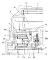
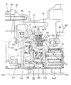
図1は本発明の一形態に係る駆動装置が組み込まれた車両の全体構成を概略的に示しており、図2は図1に示された駆動装置を詳細に示している。車両1はいわゆるハイブリッド車両として構成されている。周知のようにハイブリッド車両は、内燃機関を走行用の駆動力源として備えるとともに、電動機を他の走行用の駆動力源として備えた車両である。車両1は駆動輪と内燃機関とが車両前部に位置するFFレイアウトの車両として構成されている。
FIG. 1 schematically shows the overall configuration of a vehicle in which a driving apparatus according to an embodiment of the present invention is incorporated, and FIG. 2 shows the driving apparatus shown in FIG. 1 in detail. The
駆動装置2は、内燃機関3と、第1モータ・ジェネレータ4と、内燃機関3及び第1モータ・ジェネレータ4がそれぞれ連結された第1差動機構としての動力分配機構5と、動力分配機構5からの動力が伝達される中間回転部材としての中間軸6とを備えている。また、駆動装置2には第2差動機構としての減速機構8を介して中間軸6に連結された第2モータ・ジェネレータ9が設けられている。中間軸6の動力は変速機構10を介して出力部11に伝達され、出力部11を経由した動力は左右の駆動輪12に伝達される。第1モータ・ジェネレータ4、動力分配機構5、変速機構10、第2モータ・ジェネレータ9及び減速機構8は内燃機関3側から当該順序で図示の通りに同軸的に配置されている。
The
内燃機関3は、火花点火型の多気筒内燃機関として構成されており、その動力は入力軸15を介して動力分配機構5に伝達される。入力軸15は中間軸6と同軸に配置されていて、入力軸15及び中間軸6は共通の軸線Ax1(図2)の回りに回転する。入力軸15と内燃機関3との間にはダンパ16が介在しており、内燃機関3のトルク変動はダンパ16にて吸収される。
The
第1モータ・ジェネレータ4と第2モータ・ジェネレータ9とは同様の構成を持っていて、電動機としての機能と発電機としての機能とを兼ね備えている。第1モータ・ジェネレータ4は、ケース17に固定されたステータ18と、そのステータ18の内周側に同軸に配置されたロータ19とを備えている。第2モータ・ジェネレータ9も同様に、ケース17に固定されたステータ20と、そのステータ20の内周側に同軸に配置されたロータ21とを備えている。第1モータ・ジェネレータ4は本発明に係る第1電動機に、第2モータ・ジェネレータ9は本発明に係る第2電動機にそれぞれ相当する。図2に示すように、第2モータ・ジェネレータ9のロータ21は、電磁鋼板が積層されたロータコアを支持する支持部21aを有しており、その支持部21aは中間軸6の外周に相対回転可能な状態で同軸上に配置されている。第2モータ・ジェネレータ9のロータ21は、その右側の一端が第1支持壁25に軸受27を介して回転自在に支持されるとともに、左側の他端が第2支持壁26に軸受28を介して回転自在に支持されている。第1支持壁25及び第2支持壁26はケース17に固定されていてケース17に対して静止している。
The first motor / generator 4 and the second motor /
動力分配機構5は、相互に差動回転可能な3つの回転要素を持つシングルピニオン型の遊星歯車機構として構成されており、外歯歯車であるサンギアSu1と、そのサンギアSu1に対して同軸的に配置された内歯歯車であるリングギアRi1と、これらのギアSu1、Ri1に噛み合うピニオン30を自転かつ公転自在に保持するキャリアCr1とを備えている。この形態では、入力軸15がキャリアCr1に、第1モータ・ジェネレータ4がサンギアSu1に、中間軸6がリングギアRi1にそれぞれ連結されている。従って、本形態においては、キャリアCr1が本発明に係る第1回転要素に、サンギアSu1が本発明に係る第2回転要素に、リングギアRi1が本発明に係る第3回転要素にそれぞれ相当する。
The
減速機構8は、相互に差動回転可能な3つの回転要素を持つシングルピニオン型の遊星歯車機構として構成されている。減速機構8は第2支持壁26を挟んで第1支持壁25の反対側に配置されていて、外歯歯車であるサンギアSu2と、そのサンギアSu2に対して同軸的に配置された内歯歯車であるリングギアRi2と、これらのギアSu2、Ri2に噛み合うピニオン31を自転かつ公転自在に保持するキャリアCr2とを備えている。この形態では、第2モータ・ジェネレータ9がサンギアSu2に、ケース17(第2支持壁22)がキャリアCr2に、中間軸6がリングギアRi2にそれぞれ連結されている。従って、本形態においては、サンギアSu2が本発明に係る第4回転要素に、キャリアCr2が本発明に係る第5回転要素に、リングギアRi2が本発明に係る第6回転要素にそれぞれ相当する。また、キャリアCr2は本発明に係る固定キャリアに相当する。
The
図3は図2に示された減速機構8及びその周辺を拡大した拡大図である。この図に示すように、減速機構8のキャリアCr2にはピニオン31を回転自在に支持する支持軸34が設けられており、その支持軸34にはその外周面に開口しかつ第2支持壁26側の端部に開口する油供給路34aが形成されている。油供給路34aには第2支持壁26に形成された潤滑油路26aの一端が接続されている。その潤滑油路26aの他端は第2モータ・ジェネレータ9側に開口している。これにより、図3の矢印で示すように第2モータ・ジェネレータ9を冷却したオイルを、第2支持壁26に形成された潤滑油路26aと支持軸34に形成された油供給路34aとを通じてピニオン26へ導くことができる。このように、第2支持壁26を利用して潤滑油路26aを形成できるため、第2支持壁26と独立した潤滑油路を形成する場合と比べて潤滑油路の構成を簡略化できる。
FIG. 3 is an enlarged view of the
図1〜図3に示すように、中間軸6の左側の端部にはリングギアRi2がスプライン嵌合にて相対回転不能に装着されている(図3参照)。中間軸6は、第2モータ・ジェネレータ9のロータ21と減速機構8とが外周に配置された状態で、第1支持壁25と、第2支持壁26と、減速機構8を挟んで第2支持壁22の反対側に設けられた第3支持壁35とによって支持されている。第3支持壁35はケース17に固定されている。図2及び図3に示すように、第3支持壁35と中間軸6との間には軸受36が介在しており、その軸受36を介して中間軸6は第3支持壁35に回転自在に支持されている。
As shown in FIGS. 1 to 3, a ring gear Ri <b> 2 is attached to the left end portion of the
変速機構10は、相互に差動回転可能な3つの回転要素を持つダブルピニオン型の遊星歯車機構として構成された差動機構40と、出力部11に至る動力伝達状態を切り替える変速切替部41とを備えている。差動機構40は本発明に係る第3差動機構に相当する。差動機構40は、外歯歯車であるサンギアSu3と、そのサンギアSu3に対して同軸的に配置された内歯歯車であるリングギアRi3と、サンギアSu3に噛み合う第1ピニオン42及びリングギアRi3に噛み合う第2ピニオン43を相互に噛み合わせた状態で、これらのピニオン42、43を自転かつ公転自在に保持するキャリアCr3とを有している。変速切替部41はサンギアSu3とキャリアCr3とを結合又は解放するクラッチCLと、サンギアSu3とケース17とを結合又は解放するブレーキBとを有している。
The
変速機構10は、変速切替部41のクラッチCL及びブレーキBの各作動状態を変更することにより、ギア比が高い第1速とギア比が低い第2速とを選択的に成立させる。第1速はクラッチCLにてサンギアSu3とキャリアCr3とを解放した状態で、ブレーキBにてサンギアSu3とケース17とを結合することにより成立する。他方、第2速はクラッチCLにてサンギアSu3とキャリアCr3とを結合した状態で、ブレーキBにてサンギアSu3とケース17とを解放することにより成立する。変速機構10に対する変速制御は周知のように車速とアクセル操作量とに基づいて行われる。
The
図4は、図2に示された変速切替部41及びその周辺を拡大した拡大図である。この図にも示すように、変速切替部41は第2モータ・ジェネレータ9に隣接する第1支持壁25に配置されていて、クラッチCLとブレーキBとが軸線方向にオーバーラップした状態で集約されている。クラッチCLは、差動機構40のキャリアCr3に一体回転可能に設けられた複数の(図では4枚の)第1クラッチ板45と、第1クラッチ板45の間に配置され、サンギアSu3と一体回転できる複数の(図では4枚の)第2クラッチ板46と、第1クラッチ板45と第2クラッチ板46とを接近させるためのクラッチピストン48とを持つ多板クラッチして構成されている。他方、ブレーキBはケース17に一体回転可能に設けられた複数の(図では4枚の)第1ブレーキ板49と、第1ブレーキ板49の間に配置され、サンギアSu3と一体回転できる複数の(図では4枚の)第2ブレーキ板50と、第1ブレーキ板49と第2ブレーキ板50とを接近させるためのブレーキピストン51とを持つ多板ブレーキとして構成されている。そして、クラッチCLの第2クラッチ板46とブレーキBの第2ブレーキ板50とは軸線方向にオーバーラップした状態でサンギアSu3と一体回転できる共通の回転部材52に設けられている。第2クラッチ板46は回転部材52の回転半径方向外側に装着されており、第2ブレーキ板50は回転部材42の回転半径方向内側に装着されている。
FIG. 4 is an enlarged view in which the
クラッチCLのクラッチピストン48は回転部材52に隣接するピストン室55に収容されており、そのピストン室55にはクラッチピストン48をクラッチ板45、46から離す方向に付勢するリターンスプリング56が設けられている。ピストン室55への油圧の供給を不図示のコントロールバルブにて制御することにより、サンギアSu3とキャリアCr3とを結合する係合状態と、サンギアSu3とキャリアCr3とを解放する解放状態とを切り替えることができる。他方、ブレーキBのブレーキピストン51は第1支持壁25に形成されたピストン室57に収容されており、そのピストン室57にはブレーキピストン51をブレーキ板49、50から離す方向に付勢するリターンスプリング58が設けられている。ブレーキBもクラッチCLと同様に、ピストン室57への油圧の供給を不図示のコントロールバルブにて制御することにより、サンギアSu3とケース17とを結合する係合状態と、サンギアSu3とケース17とを解放する解放状態とを切り替えることができる。
The
変速切替部41は、第2クラッチ板46と第2ブレーキ板50とが軸線方向にオーバーラップした状態でブレーキBとクラッチCLとがまとめられているため、ブレーキBとクラッチCLとを軸線方向に並べた場合と比べて軸線方向の寸法を短縮できる。また、第2クラッチ板46と第2ブレーキ板50とが共通の回転部材52に設けられているので、部品点数を削減できるため体格の低減、軽量化及び低コスト化が可能になる。
The
図1及び図2に示すように、出力部11は、動力分配機構5及び変速機構10のそれぞれの外周側に配置されている。このため、出力部11を動力分配機構5又は変速機構10に隣接するように配置する場合に比べて軸線方向の小型化を容易に達成できる。また、出力部11は、動力分配機構5のリングギアRi1と一体回転するカウンタドライブギア60と、カウンタドライブギア60と噛み合うカウンタドリブンギア61と、カウンタドリブンギア61を経由した動力を駆動輪12(図1)に伝達する差動装置62とを有している。カウンタドリブンギア61と作動装置62との間にはカウンタドリブンギア61と同軸かつ一体回転する中間ギア63が介在しており、この中間ギア63は差動装置62のケースに設けられたドリブンギア64と噛み合っている。図2に示すように、カウンタドライブギア60、カウンタドリブンギア61及び差動装置62は、共通のケース17にて支持されている。そのため、出力部11の構成要素がケース17と別体のハウジングにて支持される形態と比較して、組み付け誤差を小さくすることができかつ支持剛性を容易に高めることができる。
As shown in FIGS. 1 and 2, the
以上の駆動装置2によれば、第2モータ・ジェネレータ9のロータ21の支持と変速切替部41の支持とを共通の第1支持壁25にて行うことができるため、これらの支持を別々の支持壁で行う形態と比較して軸線方向の寸法を短くできる。また、中間軸6が第1支持壁25と、第3支持壁35とによって支持されている。このため、中間軸6の一端の支持を第1支持壁25とは別の支持壁で行う場合と比べて中間軸6の軸線方向の寸法増大を抑えることができる。
According to the
本発明は上記の形態に限定されず、本発明の要旨の範囲内において種々の形態にて実施できる。駆動装置2の各構成要素の配置は一例であり、第1モータ・ジェネレータ4、動力分配機構5、変速機構10、第2モータ・ジェネレータ9及び減速機構8が同軸的に配置されていれば十分であり、変速機構10と第2モータ・ジェネレータ9とが隣り合う限りにおいてこれらの並び順は任意であってよい。また、上述した各形態の差動機構は一例にすぎず、これらを機構学上等価な別形態に変更することも可能である。また差動機構を遊星歯車機構により実現することは一例にすぎない。例えば、上述した各形態の遊星歯車機構の全部又は一部を、歯車ではない摩擦車(ローラ)を回転要素として持つ遊星ローラ機構に置き換えて実施することも可能である。
The present invention is not limited to the above embodiment, and can be implemented in various forms within the scope of the gist of the present invention. The arrangement of each component of the
1 車両
3 内燃機関
4 第1モータ・ジェネレータ(第1電動機)
5 動力分配機構(第1差動機構)
6 中間軸(中間回転部材)
8 減速機構(第2差動機構)
9 第2モータ・ジェネレータ(第2電動機)
10 変速機構
11 出力部
17 ケース
19 ロータ
25 第1支持壁
26 第2支持壁
26a 潤滑油路
31 ピニオン
35 第3支持壁
40 差動機構(第3差動機構)
41 変速切替部
45 第1クラッチ板
46 第2クラッチ板
49 第1ブレーキ板
50 第2ブレーキ板
52 回転部材
60 カウンタドライブギア
61 カウンタドリブンギア
62 差動装置
B ブレーキ
CL クラッチ
DESCRIPTION OF
5 Power distribution mechanism (first differential mechanism)
6 Intermediate shaft (intermediate rotating member)
8 Deceleration mechanism (second differential mechanism)
9 Second motor / generator (second electric motor)
DESCRIPTION OF
41
Claims (7)
前記ケースには、前記第2電動機に隣接して前記第2電動機のロータの一端を支持する第1支持壁と、前記第2電動機の前記ロータの他端を支持する第2支持壁とが設けられており、
前記第1支持壁に前記変速機構の前記変速切替部が配置されていることを特徴とする車両の駆動装置。 A first differential mechanism having a first electric motor, a first rotating element connected to an internal combustion engine, a second rotating element connected to the first electric motor, and a third rotating element for outputting power; and the first difference An intermediate rotating member for transmitting power output from the third rotating element of the moving mechanism, a second electric motor, a case to which a stator of the second electric motor is fixed, and a fourth rotation connected to the second electric motor A second differential mechanism having an element, a fifth rotating element coupled to the case, and a sixth rotating element coupled to the intermediate rotating member, an output unit for transmitting power to a drive wheel, and the output unit A first gear, a first gear mechanism, a gear shift mechanism that has a gear shift switching unit that switches a power transmission state up to the first gear, and that transmits the rotation of the intermediate rotation member to the output unit. And the second electric motor is coaxially arranged. And a driving device for a vehicle,
The case is provided with a first support wall that supports one end of the rotor of the second motor adjacent to the second motor, and a second support wall that supports the other end of the rotor of the second motor. And
The vehicle drive device, wherein the shift switching portion of the transmission mechanism is disposed on the first support wall.
前記第2差動機構の前記第6回転要素に連結された前記中間回転部材が、前記第1支持壁と、前記第2差動機構を挟んで前記第2支持壁の反対側に設けられた第3支持壁とによって支持されている請求項1に記載の駆動装置。 The second differential mechanism is disposed on the opposite side of the first support wall across the second support wall;
The intermediate rotation member coupled to the sixth rotation element of the second differential mechanism is provided on the opposite side of the second support wall with the first support wall and the second differential mechanism interposed therebetween. The drive device according to claim 1, wherein the drive device is supported by a third support wall.
前記第1差動機構及び前記変速機構のそれぞれの外周側に前記出力部が配置されている請求項1又は2に記載の駆動装置。 From the internal combustion engine side, the first electric motor, the first differential mechanism, the speed change mechanism, the second electric motor, and the second differential mechanism are arranged in the same axial direction in this order.
3. The drive device according to claim 1, wherein the output unit is disposed on an outer peripheral side of each of the first differential mechanism and the speed change mechanism.
前記リングギアが前記出力部に、前記キャリアが前記中間回転部材にそれぞれ連結されている請求項3に記載の駆動装置。 The transmission mechanism includes a third differential mechanism configured as a double planetary planetary gear mechanism having a sun gear, a ring gear, and a carrier that perform differential rotation with respect to each other, and the sun gear and the A clutch for coupling or releasing the carrier, and a brake for coupling or releasing the sun gear and the case;
The drive device according to claim 3, wherein the ring gear is connected to the output unit, and the carrier is connected to the intermediate rotation member.
前記ブレーキは、前記ケースに一体回転可能に設けられた複数の第1ブレーキ板と、前記第1ブレーキ板の間に配置され、前記サンギアと一体回転できる複数の第2ブレーキ板と、前記第1ブレーキ板と前記第2ブレーキ板とを接近させるためのブレーキピストンとを持つ多板ブレーキとして構成され、
前記クラッチの前記第2クラッチ板と前記ブレーキの前記第2ブレーキ板とが、前記サンギアと一体回転できる共通の回転部材に軸線方向に関してオーバーラップした状態でそれぞれ設けられている請求項5に記載の駆動装置。 The clutch includes a plurality of first clutch plates provided on the carrier so as to be integrally rotatable, a plurality of second clutch plates disposed between the first clutch plates and capable of rotating integrally with the sun gear, and the first clutch plates. And a multi-plate clutch having a clutch piston for making the second clutch plate approach,
The brake includes a plurality of first brake plates provided on the case so as to be integrally rotatable, a plurality of second brake plates disposed between the first brake plates and capable of rotating integrally with the sun gear, and the first brake plates. And a multi-plate brake having a brake piston for making the second brake plate approach,
The said 2nd clutch board of the said clutch and the said 2nd brake board of the said brake are each provided in the state which overlapped with respect to the axial direction at the common rotating member which can rotate integrally with the said sun gear. Drive device.
前記第2支持壁には、前記第2電動機を冷却したオイルを前記固定キャリアにて支持されるピニオンへ導く潤滑油路が設けられている請求項1〜6のいずれか一項に記載の駆動装置。 The second differential mechanism is configured as a single pinion type planetary gear mechanism provided as the fifth rotating element and having a fixed carrier fixed to the second support wall,
The drive according to any one of claims 1 to 6, wherein the second support wall is provided with a lubricating oil path that guides oil that has cooled the second electric motor to a pinion supported by the fixed carrier. apparatus.
Priority Applications (5)
| Application Number | Priority Date | Filing Date | Title |
|---|---|---|---|
| JP2008274586A JP4708467B2 (en) | 2008-10-24 | 2008-10-24 | Vehicle drive device |
| PCT/IB2009/007203 WO2010046765A1 (en) | 2008-10-24 | 2009-10-22 | Vehicular drive apparatus |
| EP09764025A EP2349769B1 (en) | 2008-10-24 | 2009-10-22 | Vehicular drive apparatus |
| CN2009801275225A CN102089171B (en) | 2008-10-24 | 2009-10-22 | Vehicular drive apparatus |
| US13/057,074 US8469848B2 (en) | 2008-10-24 | 2009-10-22 | Vehicular drive apparatus |
Applications Claiming Priority (1)
| Application Number | Priority Date | Filing Date | Title |
|---|---|---|---|
| JP2008274586A JP4708467B2 (en) | 2008-10-24 | 2008-10-24 | Vehicle drive device |
Publications (2)
| Publication Number | Publication Date |
|---|---|
| JP2010100216A true JP2010100216A (en) | 2010-05-06 |
| JP4708467B2 JP4708467B2 (en) | 2011-06-22 |
Family
ID=41600458
Family Applications (1)
| Application Number | Title | Priority Date | Filing Date |
|---|---|---|---|
| JP2008274586A Expired - Fee Related JP4708467B2 (en) | 2008-10-24 | 2008-10-24 | Vehicle drive device |
Country Status (5)
| Country | Link |
|---|---|
| US (1) | US8469848B2 (en) |
| EP (1) | EP2349769B1 (en) |
| JP (1) | JP4708467B2 (en) |
| CN (1) | CN102089171B (en) |
| WO (1) | WO2010046765A1 (en) |
Cited By (5)
| Publication number | Priority date | Publication date | Assignee | Title |
|---|---|---|---|---|
| JP2015020726A (en) * | 2013-07-23 | 2015-02-02 | トヨタ自動車株式会社 | Driving device for hybrid vehicle |
| JP2015027850A (en) * | 2013-07-30 | 2015-02-12 | トヨタ自動車株式会社 | Hybrid system |
| JP2015027851A (en) * | 2013-07-30 | 2015-02-12 | トヨタ自動車株式会社 | Hybrid system |
| JPWO2013094043A1 (en) * | 2011-12-21 | 2015-04-27 | トヨタ自動車株式会社 | Vehicle control device |
| JP2018515721A (en) * | 2015-03-20 | 2018-06-14 | ドクター エンジニール ハー ツェー エフ ポルシェ アクチエンゲゼルシャフトDr. Ing. h.c. F. Porsche Aktiengesellschaft | Electric axle drive for automobile |
Families Citing this family (22)
| Publication number | Priority date | Publication date | Assignee | Title |
|---|---|---|---|---|
| US8337352B2 (en) * | 2010-06-22 | 2012-12-25 | Oshkosh Corporation | Electromechanical variable transmission |
| BR112013006687A2 (en) * | 2010-09-30 | 2016-06-07 | Honda Motor Co Ltd | vehicle drive system |
| US8968133B2 (en) * | 2011-05-26 | 2015-03-03 | Miva Engineering Ltd. | Dynamic ratio speed increaser for windmills and similar applications |
| CN103814237B (en) * | 2011-09-26 | 2016-05-18 | 日本精工株式会社 | Electric automobile-use drive unit |
| CA2822275C (en) * | 2012-07-30 | 2020-07-14 | Mcmaster University | Electro-mechanical double-rotor compound hybrid transmission |
| CN104070986B (en) * | 2013-03-28 | 2017-02-08 | 比亚迪股份有限公司 | Hybrid power assembly machine body and automobile using same |
| US9303696B2 (en) | 2013-08-23 | 2016-04-05 | American Axle & Manufacturing, Inc. | Optimized outer clutch housing for reduced spin loss, improved oil flow and improved clutch durability |
| US9109674B2 (en) * | 2013-10-14 | 2015-08-18 | Fca Us Llc | Enhanced electrically variable drive unit |
| US9261186B2 (en) * | 2014-03-04 | 2016-02-16 | Gm Global Technology Operations, Llc | Rotating clutch pack assembly |
| US9453572B2 (en) * | 2014-04-16 | 2016-09-27 | GM Global Technology Operations LLC | Electro-mechanical drive system |
| DE102014209056A1 (en) * | 2014-05-14 | 2015-11-19 | Zf Friedrichshafen Ag | Hybrid drive arrangement of a motor vehicle |
| US10578195B2 (en) | 2015-02-17 | 2020-03-03 | Oshkosh Corporation | Inline electromechanical variable transmission system |
| US10421350B2 (en) | 2015-10-20 | 2019-09-24 | Oshkosh Corporation | Inline electromechanical variable transmission system |
| US11701959B2 (en) | 2015-02-17 | 2023-07-18 | Oshkosh Corporation | Inline electromechanical variable transmission system |
| US9651120B2 (en) | 2015-02-17 | 2017-05-16 | Oshkosh Corporation | Multi-mode electromechanical variable transmission |
| US10982736B2 (en) | 2015-02-17 | 2021-04-20 | Oshkosh Corporation | Multi-mode electromechanical variable transmission |
| US9650032B2 (en) | 2015-02-17 | 2017-05-16 | Oshkosh Corporation | Multi-mode electromechanical variable transmission |
| US10584775B2 (en) | 2015-02-17 | 2020-03-10 | Oshkosh Corporation | Inline electromechanical variable transmission system |
| US9656659B2 (en) | 2015-02-17 | 2017-05-23 | Oshkosh Corporation | Multi-mode electromechanical variable transmission |
| US11137053B2 (en) * | 2019-07-15 | 2021-10-05 | Oshkosh Corporation | Three planetary inline emivt |
| DE102020115666B4 (en) | 2020-06-15 | 2023-06-29 | Iav Gmbh Ingenieurgesellschaft Auto Und Verkehr | Electric vehicle drive with multi-speed gearbox |
| DE102020115664B4 (en) | 2020-06-15 | 2023-06-15 | Iav Gmbh Ingenieurgesellschaft Auto Und Verkehr | Electric vehicle drive with multi-speed gearbox |
Citations (6)
| Publication number | Priority date | Publication date | Assignee | Title |
|---|---|---|---|---|
| JP2005170159A (en) * | 2003-12-09 | 2005-06-30 | Aisin Aw Co Ltd | Hybrid driving device |
| JP2006175951A (en) * | 2004-12-21 | 2006-07-06 | Toyota Motor Corp | Vehicle driving device |
| JP2006322520A (en) * | 2005-05-18 | 2006-11-30 | Toyota Motor Corp | Power output system, automobile having the same, and controlling method thereof |
| JP2007131235A (en) * | 2005-11-11 | 2007-05-31 | Toyota Motor Corp | Drive device for hybrid vehicle |
| WO2008075760A1 (en) * | 2006-12-18 | 2008-06-26 | Toyota Jidosha Kabushiki Kaisha | Hybrid drive device |
| JP2008195196A (en) * | 2007-02-13 | 2008-08-28 | Toyota Motor Corp | Driving device for hybrid vehicle |
Family Cites Families (13)
| Publication number | Priority date | Publication date | Assignee | Title |
|---|---|---|---|---|
| JP2967103B2 (en) | 1993-05-24 | 1999-10-25 | 株式会社エクォス・リサーチ | Hybrid vehicle |
| US6743135B2 (en) * | 2001-09-28 | 2004-06-01 | General Motors Corporation | Modularly-constructed vehicular transmissions |
| JP3536837B2 (en) | 2001-12-26 | 2004-06-14 | トヨタ自動車株式会社 | Drive unit for hybrid vehicle |
| JP3945470B2 (en) | 2003-10-23 | 2007-07-18 | 日産自動車株式会社 | Mode change control device for hybrid transmission |
| US7822524B2 (en) * | 2003-12-26 | 2010-10-26 | Toyota Jidosha Kabushiki Kaisha | Vehicular drive system |
| US7247112B2 (en) * | 2004-03-22 | 2007-07-24 | Gm Global Technology Operations, Inc. | Method and apparatus for cooling and lubricating a hybrid transmission |
| US7002267B2 (en) | 2004-03-22 | 2006-02-21 | General Motors Corporation | Method and apparatus for cooling a hybrid transmission electric motor |
| US7766778B2 (en) * | 2004-09-14 | 2010-08-03 | Toyota Jidosha Kabushiki Kaisha | Drive device for vehicle |
| JP4059876B2 (en) * | 2004-10-14 | 2008-03-12 | トヨタ自動車株式会社 | Hybrid drive device |
| JP4258496B2 (en) * | 2005-06-24 | 2009-04-30 | トヨタ自動車株式会社 | Vehicle drive device |
| US7645206B2 (en) * | 2007-02-26 | 2010-01-12 | Gm Global Technology Operations, Inc. | Three mode electrically-variable transmission |
| US8224544B2 (en) * | 2007-11-07 | 2012-07-17 | GM Global Technology Operations LLC | Method and apparatus to control launch of a vehicle having an electro-mechanical transmission |
| US8221279B2 (en) * | 2008-04-04 | 2012-07-17 | GM Global Technology Operations LLC | Dual apply clutch apparatus for compact electro-mechanical transmission |
-
2008
- 2008-10-24 JP JP2008274586A patent/JP4708467B2/en not_active Expired - Fee Related
-
2009
- 2009-10-22 WO PCT/IB2009/007203 patent/WO2010046765A1/en active Application Filing
- 2009-10-22 US US13/057,074 patent/US8469848B2/en not_active Expired - Fee Related
- 2009-10-22 EP EP09764025A patent/EP2349769B1/en not_active Not-in-force
- 2009-10-22 CN CN2009801275225A patent/CN102089171B/en not_active Expired - Fee Related
Patent Citations (6)
| Publication number | Priority date | Publication date | Assignee | Title |
|---|---|---|---|---|
| JP2005170159A (en) * | 2003-12-09 | 2005-06-30 | Aisin Aw Co Ltd | Hybrid driving device |
| JP2006175951A (en) * | 2004-12-21 | 2006-07-06 | Toyota Motor Corp | Vehicle driving device |
| JP2006322520A (en) * | 2005-05-18 | 2006-11-30 | Toyota Motor Corp | Power output system, automobile having the same, and controlling method thereof |
| JP2007131235A (en) * | 2005-11-11 | 2007-05-31 | Toyota Motor Corp | Drive device for hybrid vehicle |
| WO2008075760A1 (en) * | 2006-12-18 | 2008-06-26 | Toyota Jidosha Kabushiki Kaisha | Hybrid drive device |
| JP2008195196A (en) * | 2007-02-13 | 2008-08-28 | Toyota Motor Corp | Driving device for hybrid vehicle |
Cited By (6)
| Publication number | Priority date | Publication date | Assignee | Title |
|---|---|---|---|---|
| JPWO2013094043A1 (en) * | 2011-12-21 | 2015-04-27 | トヨタ自動車株式会社 | Vehicle control device |
| US9463789B2 (en) | 2011-12-21 | 2016-10-11 | Toyota Jidosha Kabushiki Kaisha | Control device for vehicle |
| JP2015020726A (en) * | 2013-07-23 | 2015-02-02 | トヨタ自動車株式会社 | Driving device for hybrid vehicle |
| JP2015027850A (en) * | 2013-07-30 | 2015-02-12 | トヨタ自動車株式会社 | Hybrid system |
| JP2015027851A (en) * | 2013-07-30 | 2015-02-12 | トヨタ自動車株式会社 | Hybrid system |
| JP2018515721A (en) * | 2015-03-20 | 2018-06-14 | ドクター エンジニール ハー ツェー エフ ポルシェ アクチエンゲゼルシャフトDr. Ing. h.c. F. Porsche Aktiengesellschaft | Electric axle drive for automobile |
Also Published As
| Publication number | Publication date |
|---|---|
| CN102089171B (en) | 2013-11-13 |
| JP4708467B2 (en) | 2011-06-22 |
| CN102089171A (en) | 2011-06-08 |
| US8469848B2 (en) | 2013-06-25 |
| EP2349769B1 (en) | 2012-09-05 |
| US20110143875A1 (en) | 2011-06-16 |
| WO2010046765A1 (en) | 2010-04-29 |
| EP2349769A1 (en) | 2011-08-03 |
Similar Documents
| Publication | Publication Date | Title |
|---|---|---|
| JP4708467B2 (en) | Vehicle drive device | |
| CN101405161B (en) | Power transmission device and method of assembling the same | |
| JP5855843B2 (en) | Drive device | |
| JP6052435B2 (en) | Hybrid drive unit | |
| WO2011034191A9 (en) | Hybrid drive device | |
| WO2015099075A1 (en) | Drive device | |
| JP2009101729A (en) | Hybrid drive device | |
| JP5218031B2 (en) | Vehicle drive device | |
| JP5821620B2 (en) | Hybrid drive unit | |
| WO2012141056A1 (en) | Transmission device | |
| CN103328855B (en) | Automatic transmission | |
| JP2010223298A (en) | Electric motor driving device | |
| JP5062122B2 (en) | Vehicle drive device | |
| WO2012141060A1 (en) | Transmission apparatus | |
| JP2010052518A (en) | Driving device of hybrid vehicle | |
| JP2018118616A (en) | Vehicle drive device | |
| WO2018181557A1 (en) | Vehicle drive device | |
| JP2005132365A (en) | Hybrid driving device and automobile mounted with the same device | |
| JP2008002550A (en) | Power transmission device | |
| JP2010159022A (en) | Drive unit for vehicle | |
| JP2008149839A (en) | Belt type continuously variable transmission | |
| JP6146320B2 (en) | Power transmission device | |
| JP2014162373A (en) | Driving force distribution device | |
| JP2019049320A (en) | Drive device for vehicle | |
| JP2007239773A (en) | Automatic transmission |
Legal Events
| Date | Code | Title | Description |
|---|---|---|---|
| A521 | Written amendment |
Free format text: JAPANESE INTERMEDIATE CODE: A821 Effective date: 20100603 |
|
| A711 | Notification of change in applicant |
Free format text: JAPANESE INTERMEDIATE CODE: A711 Effective date: 20100603 |
|
| RD02 | Notification of acceptance of power of attorney |
Free format text: JAPANESE INTERMEDIATE CODE: A7422 Effective date: 20100603 |
|
| A521 | Written amendment |
Free format text: JAPANESE INTERMEDIATE CODE: A821 Effective date: 20100603 |
|
| A131 | Notification of reasons for refusal |
Free format text: JAPANESE INTERMEDIATE CODE: A131 Effective date: 20100727 |
|
| A521 | Written amendment |
Free format text: JAPANESE INTERMEDIATE CODE: A523 Effective date: 20100924 |
|
| A01 | Written decision to grant a patent or to grant a registration (utility model) |
Free format text: JAPANESE INTERMEDIATE CODE: A01 Effective date: 20110222 |
|
| A61 | First payment of annual fees (during grant procedure) |
Free format text: JAPANESE INTERMEDIATE CODE: A61 Effective date: 20110316 |
|
| R250 | Receipt of annual fees |
Free format text: JAPANESE INTERMEDIATE CODE: R250 |
|
| R250 | Receipt of annual fees |
Free format text: JAPANESE INTERMEDIATE CODE: R250 |
|
| R250 | Receipt of annual fees |
Free format text: JAPANESE INTERMEDIATE CODE: R250 |
|
| R250 | Receipt of annual fees |
Free format text: JAPANESE INTERMEDIATE CODE: R250 |
|
| LAPS | Cancellation because of no payment of annual fees |