JP2010099768A - Cutting device - Google Patents
Cutting device Download PDFInfo
- Publication number
- JP2010099768A JP2010099768A JP2008272599A JP2008272599A JP2010099768A JP 2010099768 A JP2010099768 A JP 2010099768A JP 2008272599 A JP2008272599 A JP 2008272599A JP 2008272599 A JP2008272599 A JP 2008272599A JP 2010099768 A JP2010099768 A JP 2010099768A
- Authority
- JP
- Japan
- Prior art keywords
- guide
- cutting device
- lower drum
- drum
- cutting
- Prior art date
- Legal status (The legal status is an assumption and is not a legal conclusion. Google has not performed a legal analysis and makes no representation as to the accuracy of the status listed.)
- Granted
Links
Images

Classifications
-
- B—PERFORMING OPERATIONS; TRANSPORTING
- B23—MACHINE TOOLS; METAL-WORKING NOT OTHERWISE PROVIDED FOR
- B23D—PLANING; SLOTTING; SHEARING; BROACHING; SAWING; FILING; SCRAPING; LIKE OPERATIONS FOR WORKING METAL BY REMOVING MATERIAL, NOT OTHERWISE PROVIDED FOR
- B23D25/00—Machines or arrangements for shearing stock while the latter is travelling otherwise than in the direction of the cut
- B23D25/12—Shearing machines with blades on coacting rotating drums
-
- B—PERFORMING OPERATIONS; TRANSPORTING
- B21—MECHANICAL METAL-WORKING WITHOUT ESSENTIALLY REMOVING MATERIAL; PUNCHING METAL
- B21B—ROLLING OF METAL
- B21B39/00—Arrangements for moving, supporting, or positioning work, or controlling its movement, combined with or arranged in, or specially adapted for use in connection with, metal-rolling mills
- B21B39/02—Feeding or supporting work; Braking or tensioning arrangements, e.g. threading arrangements
-
- B—PERFORMING OPERATIONS; TRANSPORTING
- B23—MACHINE TOOLS; METAL-WORKING NOT OTHERWISE PROVIDED FOR
- B23D—PLANING; SLOTTING; SHEARING; BROACHING; SAWING; FILING; SCRAPING; LIKE OPERATIONS FOR WORKING METAL BY REMOVING MATERIAL, NOT OTHERWISE PROVIDED FOR
- B23D19/00—Shearing machines or shearing devices cutting by rotary discs
- B23D19/04—Shearing machines or shearing devices cutting by rotary discs having rotary shearing discs arranged in co-operating pairs
Landscapes
- Engineering & Computer Science (AREA)
- Mechanical Engineering (AREA)
- Metal Rolling (AREA)
- Shearing Machines (AREA)
- Milling Processes (AREA)
Abstract
Description
本発明は、切断装置に関する。 The present invention relates to a cutting device.
金属素材(スラブなど)を粗圧延機により粗圧延してなる金属板の先端と後端とを複数の仕上圧延機からなる仕上圧延機群の前に配置される切断装置(以下、仕上前CSと称す)により切断し、複数の仕上圧延機により所望の板厚まで圧延する(仕上げ圧延する)工程を一つのスラブ毎に行う熱間圧延設備が知られている。 A cutting device (hereinafter referred to as CS before finishing) in which a metal plate (such as a slab) is roughly rolled by a roughing mill, and the front and rear ends of a metal plate are arranged in front of a finishing mill group consisting of a plurality of finishing rolling mills. And hot rolling equipment that performs a process of rolling to a desired sheet thickness (finish rolling) for each slab by a plurality of finish rolling mills.
また、上述した熱間圧延設備において、粗圧延機と仕上前CSとの間に接合機を設置することで、この接合機により複数の金属板を先行の金属板の後端と後行の金属板の先端とを接合し連続して仕上げ圧延する熱間圧延設備も知られている。このような熱間圧延設備では、接合機の入側(粗圧延機と接合機との間)に切断装置(以下、接合前CSと称す)が配置されており、先行材の金属板の後端と後行材の金属板の先端、いわゆる接合面のクロップが切り落とされている。 Moreover, in the hot rolling facility described above, a joining machine is installed between the rough rolling mill and the pre-finishing CS so that a plurality of metal plates can be connected to the rear end of the preceding metal plate and the following metal by this joining machine. There is also known a hot rolling facility that joins the front end of a plate and continuously performs finish rolling. In such a hot rolling facility, a cutting device (hereinafter referred to as CS before joining) is arranged on the entry side of the joining machine (between the roughing mill and the joining machine), and after the metal plate of the preceding material The end and the tip of the metal plate of the succeeding material, so-called joint surface crops, are cut off.
さらに、上述した、接合機を有する熱間圧延設備においても、一つのスラブ毎に仕上げ圧延するバッチ処理が行う場合には、上記接合前CSを使用せず、上記仕上前CSのみを使用している。 Furthermore, even in the above-described hot rolling equipment having a joining machine, when performing batch processing for finish rolling for each slab, the pre-joining CS is not used, and only the pre-finishing CS is used. Yes.
上述した接合前CSは、切断したクロップをそのまま下方に落とすための空間を入側および出側にそれぞれ具備している。このような接合前CSにおいて、バッチ処理する際の金属板の通板性を向上させるため種々の技術が開発されている。例えば、特許文献1には、クロップシャ本体出側に配置された出側エプロンを具備した接合用クロップシャが記載され、特許文献2には、クロップシャーをオフラインに移動させる移動手段とこのクロップシャーの移動に合わせてオンラインに移動可能な鋼片搬送用テーブルローラを具備した鋼片の連続熱間圧延設備列が記載され、特許文献3には、シャーフレームの入側および出側にローラテーブルユニットを配置したクロップシャーが記載されている。 The above-mentioned pre-joining CS includes spaces for dropping the cut crop as it is on the entry side and the exit side. In such a pre-joining CS, various techniques have been developed in order to improve the plate-through property of the metal plate during batch processing. For example, Patent Document 1 describes a joining cropper having an output apron disposed on the cropping body main body output side, and Patent Document 2 discloses a moving means for moving the crop shear offline and the crop shear. A steel strip continuous hot rolling equipment line having a steel piece transporting table roller that can be moved online in accordance with the movement of the steel frame is described. Patent Document 3 discloses a roller table unit on the inlet side and the outlet side of the shear frame. A crop shear in which is arranged is described.
しかしながら、上述した特許文献1に記載の接合用クロップシャでは、出側エプロンにより鋼片を下方から支持して前記鋼片の通板性を向上させることができるものの、このクロップシャの入側に配置されるテーブルローラと前記出側エプロンとの間の距離が長く、鋼片の先端が上反ったり下反ったり、また鋼片自体が撓んだりして、この鋼片の先端または後端と下ドラムとの接触により傷が付与されてしまう可能性があった。 However, in the cropping joint described in Patent Document 1 described above, although the steel piece can be supported from below by the output apron to improve the plate-through property of the steel piece, The distance between the table roller to be arranged and the outlet apron is long, the tip of the steel piece is warped up or down, or the steel piece itself is bent, There was a possibility that scratches were imparted by contact with the lower drum.
また、上述した特許文献2に記載の鋼片の連続熱間圧延設備列では、鋼片搬送用テーブルローラにより鋼片の通板性を向上させることができるものの、移動手段によりクロップシャーおよび鋼片搬送用テーブルローラを移動させてオンラインとオフラインとを切替えるため、この切り替えに時間を要し、生産性を低下させてしまう。 Moreover, in the continuous hot-rolling equipment row | line | column of the steel slab described in patent document 2 mentioned above, although the plate | board property of a steel slab can be improved with the table roller for steel slab conveyance, a crop shear and a steel slab by a moving means Since the transfer table roller is moved to switch between online and offline, this switching takes time and reduces productivity.
上述した特許文献3に記載のクロップシャーでは、ローラテーブルユニットにより帯状材の通板性は向上するものの、ローラテーブルユニットが帯状材の通板経路に配置されるため、帯状材のクロップを切断した場合に、前記ローラテーブルユニットにより、切断されたクロップの通板経路からの除去を妨げてしまう可能性があった。 In the crop shear described in Patent Document 3 described above, the roller table unit improves the sheet-passing property of the belt-shaped material, but the roller table unit is arranged in the belt-shaped material threading plate path, so the crop of the belt-shaped material is cut. In some cases, the roller table unit may prevent the cut crop from being removed from the passage plate path.
そこで、本発明は、前述した問題に鑑み提案されたもので、切断されたクロップの除去のためのスペースを確保しつつ、金属板の通板性を向上させ、生産性の低下を抑制した切断装置を提供することを目的とする。 Accordingly, the present invention has been proposed in view of the above-described problems, and while ensuring a space for removing the cut crop, the cutting performance of the metal plate is improved and the productivity is suppressed from being lowered. An object is to provide an apparatus.
上述した課題を解決する第1の発明に係る切断装置は、
金属板の通板経路の上方および下方にそれぞれ配置され、切断刃が組み付けられた上ドラムおよび下ドラムを備え、前記上ドラムと前記下ドラムとを回転駆動して前記金属板を切断する切断装置であって、
前記金属板の通板経路の入側またはその出側またはこれら両方に配置され、前記金属板を通板するガイドローラを有し、前記金属板を前記上ドラムと前記下ドラムとの間へ案内するガイド機構と、
前記ガイド機構を、前記金属板を前記上ドラムと前記下ドラムとの間へ案内する案内位置と、前記案内位置から離間した退避位置との間で移動させる移動手段とを具備した
ことを特徴とする。
The cutting device according to the first invention for solving the above-described problem is as follows.
A cutting apparatus that includes an upper drum and a lower drum, which are respectively disposed above and below the plate passage of the metal plate, and in which cutting blades are assembled, and which cuts the metal plate by rotationally driving the upper drum and the lower drum. Because
A guide roller that passes through the metal plate, and guides the metal plate between the upper drum and the lower drum. A guide mechanism to
And a moving means for moving the guide mechanism between a guide position for guiding the metal plate between the upper drum and the lower drum and a retracted position spaced apart from the guide position. To do.
上述した課題を解決する第2の発明に係る切断装置は、第1の発明に係る切断装置であって、
前記移動手段が前記ガイド機構を前記案内位置に位置付けたときに、前記ガイドローラと前記下ドラムとの間に配置される遮蔽部材を具備する
ことを特徴とする。
The cutting device according to the second invention for solving the above-described problem is the cutting device according to the first invention,
The moving unit includes a shielding member disposed between the guide roller and the lower drum when the guide mechanism is positioned at the guide position.
上述した課題を解決する第3の発明に係る切断装置は、第2の発明に係る切断装置であって、
前記下ドラムの外周に突起部が設けられ、
前記移動手段が前記ガイド機構を前記案内位置に位置付けたときに、前記下ドラムを制御して前記突起部を前記遮蔽部材に近接して配置する下ドラム制御手段を具備する
ことを特徴とする。
A cutting device according to a third invention for solving the above-described problem is a cutting device according to the second invention,
Protrusions are provided on the outer periphery of the lower drum,
When the moving means positions the guide mechanism at the guide position, the lower drum is controlled to dispose the protrusion close to the shielding member by controlling the lower drum.
第1の発明に係る切断装置によれば、移動手段がガイド機構を案内位置に位置付けたときに、切断装置における金属板の入側および出側に配置され、金属板を通板するテーブルローラの間にガイドローラが配置される。よって、このガイドローラが金属板を支持でき、前記テーブルローラと前記ガイドローラとの間の距離を、従来の切断装置の入側および出側に配置されるテーブルローラ間の距離よりも短くすることができ、金属板の上反りおよび下反りならびに金属板自体の撓みによる切断装置の入側および出側に設けられる、切断されたクロップの除去スペースへの入り込みを抑制でき、切断装置内の金属板の通板性が向上する。また、移動手段がガイド機構を退避位置に位置付けることで、切断されたクロップの除去のためのスペースを確保することができる。また、前記移動手段による前記ガイド機構の位置調整も容易であり、生産性の低下を抑制できる。 According to the cutting device of the first invention, when the moving means positions the guide mechanism at the guide position, the table roller is disposed on the entry side and the exit side of the metal plate in the cutting device and passes the metal plate. A guide roller is disposed therebetween. Therefore, this guide roller can support the metal plate, and the distance between the table roller and the guide roller is made shorter than the distance between the table rollers arranged on the entry side and the exit side of the conventional cutting device. The metal plate in the cutting device can be prevented from entering the removal space of the cut crop provided on the entry side and the exit side of the cutting device due to the upper and lower warpage of the metal plate and the bending of the metal plate itself. Improves the threadability. Further, since the moving means positions the guide mechanism at the retracted position, a space for removing the cut crop can be secured. Further, the position of the guide mechanism can be easily adjusted by the moving means, and a reduction in productivity can be suppressed.
第2の発明に係る切断装置によれば、第1の発明に係る切断装置と同様な作用効果を奏する他、移動手段がガイド機構を案内位置に位置付けたときに、ガイドローラと下ドラムとの間に配置される遮蔽部材を具備することにより、金属板の下反りによるガイドローラと下ドラムとの間への当該金属板の入り込みが防止され、金属板の通板性がさらに向上する。 According to the cutting device according to the second invention, in addition to the same operational effects as the cutting device according to the first invention, when the moving means positions the guide mechanism at the guide position, the guide roller and the lower drum By providing the shielding member disposed between them, the metal plate is prevented from entering between the guide roller and the lower drum due to the downward warping of the metal plate, and the plate passing property of the metal plate is further improved.
第3の発明に係る切断装置によれば、第2の発明に係る切断装置と同様な作用効果を奏する他、下ドラムの外周に突起部が設けられ、移動手段がガイド機構を案内位置に位置付けたときに、下ドラムを制御して突起部を遮蔽部材に近接して配置する下ドラム制御手段を具備することにより、下ドラムとガイド機構との間への金属板の入り込みが防止され、金属板の通板性がさらに向上する。 According to the cutting device according to the third invention, the same effect as the cutting device according to the second invention is obtained, and a protrusion is provided on the outer periphery of the lower drum, and the moving means positions the guide mechanism at the guide position. The lower drum is controlled to dispose the metal plate between the lower drum and the guide mechanism. The plate-through property of the plate is further improved.
以下に、本発明に係る切断装置を実施するための最良の形態を実施例に基づき具体的に説明する。 Hereinafter, the best mode for carrying out the cutting device according to the present invention will be specifically described based on examples.
本発明の第1の実施例に係る切断装置について、図1〜図3を参照して説明する。
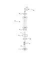
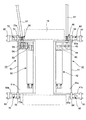
図1は、本発明の第1の実施例に係る切断装置を具備する熱間圧延設備の概略図である。図2は切断装置の側面図であり、図3は切断装置が具備するガイド機構の平面図である。図2にて、切断装置が具備するガイド機構を案内位置に位置付けた場合を実線にて示し、前記ガイド機構を退避位置に位置付けた場合を二点鎖線にて示す。
A cutting apparatus according to a first embodiment of the present invention will be described with reference to FIGS.
FIG. 1 is a schematic view of a hot rolling facility equipped with a cutting device according to a first embodiment of the present invention. FIG. 2 is a side view of the cutting device, and FIG. 3 is a plan view of a guide mechanism provided in the cutting device. In FIG. 2, the case where the guide mechanism included in the cutting device is positioned at the guide position is indicated by a solid line, and the case where the guide mechanism is positioned at the retracted position is indicated by a two-dot chain line.
本発明の第1の実施例に係る切断装置を具備する熱間圧延設備は、図1に示すように、上流側から粗圧延機(以下、粗ミルと称す)1、コイルボックス2、接合機3、複数段の圧延機により構成される仕上圧延機(以下、仕上ミルと称す)4およびダウンコイラー5を備える。
As shown in FIG. 1, a hot rolling facility equipped with a cutting device according to a first embodiment of the present invention includes a rough rolling mill (hereinafter referred to as a rough mill) 1, a coil box 2, and a joining machine as shown in FIG. 3. A finishing mill (hereinafter referred to as a finishing mill) 4 and a
粗ミル1でスラブが圧延されてなる金属板6,7はコイルボックス2のコイラーに巻き取られる。コイルボックス2のコイラーから巻き出された後行金属板6は後行金属板6の先端を接合前切断装置10により切断された後、接合機3で必要に応じて接合前切断装置10により端部が切断された先行金属板7の後端と接合機3で接合される。
The
接合機3で接合されて連続状態となった金属板(連続帯鋼)および接合機3で接合しなかった金属板は、仕上ミル4に送られる。
The metal plate (continuous strip steel) joined by the joining machine 3 and made into a continuous state and the metal plate not joined by the joining machine 3 are sent to the
仕上ミル4に送られた金属板7は複数段の圧延機により順次熱間圧延されて所望の板厚に圧延され、所望の板厚に圧延された金属板7はダウンコイラー5に巻き取られる。ダウンコイラー5の入側(仕上ミル4の出側)には切断手段8が配置され、この切断手段8により所定の部位が切断されて製品コイルとなる。
The metal plate 7 sent to the finishing
図1中の符号で、9は仕上ミルの入側に設けられた仕上前切断装置であり、この仕上前切断装置9により金属板の先端および後端が切断される。
なお、仕上前切断装置9の配置は、熱間圧延設備の状況などにより適宜選択して配置されるものであり、配置位置や配置の有無などは図示例に限定されるものではない。
In FIG. 1,
In addition, arrangement | positioning of the
ここで、以下に接合前切断装置10について、図2および図3を参照して詳細に説明する。
接合前切断装置10は、図2に示すように、ハウジング18内における、金属板6,7の通板経路の上方に配置され、2つの切断刃11a,11bが組み付けられた上ドラム13と、金属板6,7の通板経路の下方に配置され、2つの切断刃12a,12bが組み付けられた下ドラム14とを有し、上ドラム13と下ドラム14とを回転駆動して金属板6,7を切断する切断装置である。
Here, the
As shown in FIG. 2, the
上述した接合前切断装置10では、金属板6,7を通板するガイドローラ42,52を有し、金属板6,7を上ドラム13と下ドラム14との間へ案内するガイド機構40,50が設けられている。さらに、接合前切断装置10では、ガイド機構40,50を、金属板6,7を上ドラム13と下ドラム14との間へ案内する案内位置と、この案内位置から離間し、金属板の通板経路の外側である退避位置との間で移動させる移動機構60,70(移動手段)が設けられている。接合前切断装置10の金属板6,7の入側および出側には、テーブルローラ19が複数配置されており、これにより金属板6,7が通板される。
In the
上ドラム13は、回転方向に沿う断面にて長径と短径を有する略楕円状に形成されている。切断刃11aと切断刃11bとは、上ドラム13の長径をなす円弧状の周面に対向して配置される。すなわち、切断刃11aと切断刃11bとは、上ドラム13の長径をなす円弧状の周面にて同一平面上に配置される。金属板6,7を切断しない場合には、上ドラム13の長径(切断刃11aと切断刃11b)が水平となる位置に配置されて、上ドラム13が停止される。
The
他方、下ドラム14は、回転方向に沿う断面にて略円状に形成されている。切断刃12aと切断刃12bとは、下ドラム14の周面に対向して配置される。すなわち、切断刃12aと切断刃12bとは、下ドラム14の周面にて同一平面上に配置される。また、この下ドラム14の外周には、外側へ向けて突出する突起部14aが複数設けられる。金属板6,7を切断しない場合には、切断刃12aと切断刃12bが水平となる位置に配置されて、下ドラム14が停止される。
On the other hand, the
なお、上述した上ドラム13および下ドラム14は、図示しない駆動源により同期して回転駆動される。
The
上述したガイド機構40,50は、図2および図3に示すように、接合前切断装置10の金属板6,7の入側および出側にそれぞれ配置される。接合前切断装置10の金属板6,7の入側および出側に配置されたガイド機構40,50は、ガイドローラ42,52を回転可能に支持し、上方が開放した箱状の取付部41a,51aと、この取付部41a,51aに連続し、軸体81,82を介して回動可能に支持する支持部41b,51bとからなるガイド機構本体41,51を有する。ガイドローラ42,52の端部にはギヤ43,53がそれぞれ設けられる。このギヤ43,53は、それぞれ第1のギヤ44,54、第2のギヤ45,55、軸継手46,56、およびシャフト47,57を介して、図示しないモータに連結される。このモータを駆動することで、ガイドローラ42,52が回転し、この回転により金属板6,7が通板される。
The
上述したガイド機構本体41,51の取付部41a,51aは、下ドラム14側に位置すると共に、金属板6,7の通板経路の下方に位置し、下ドラム14の外周に沿って延在する側壁48,58と、この側壁48,58近傍の上方のみを遮蔽する遮蔽部材49,59を具備する。すなわち、移動機構60,70がガイド機構40,50を案内位置に位置付けたときに、ガイドローラ42,52と下ドラム14との間に配置される遮蔽部材49,59を具備することで、金属板6,7の下反りによるガイドローラ42,52と下ドラム14との間への当該金属板6,7の入り込みが防止され、金属板6,7の通板性がさらに向上する。
The mounting
上述した移動機構60,70は、一端部側が軸体61,71を介し回転可能に固定されたシリンダ62,72と、シリンダ62,72内への油圧などの給排により伸縮するロッド63,73とを有する。ロッドの先端部63a,73aは、軸体64,74を介してガイド機構本体41,51にそれぞれ支持される。
The above-described moving
上述した接合前切断装置10では、移動機構60,70がガイド機構40,50を案内位置に位置付けたときに、下ドラム14を制御して下ドラム14の突起部14aをガイド機構40,50の遮蔽部材49,59に近接して配置する図示しない下ドラム制御装置(下ドラム制御手段)が設けられている。
In the
すなわち、上述した接合前切断装置10では、複数の金属板を接合してなる連続帯鋼を処理するなど、ガイド機構40,50を使用しない場合には、シリンダ62,72への油圧の給排によりロッド63,73が収縮し、これに伴い軸体64,74を支点としガイド機構40,50が回動して引き上げられ、金属板6,7の通板経路の外側である退避位置に配置される。他方、単一の金属板を処理するなど、ガイド機構40,50を使用する場合には、シリンダ62,72への油圧の給排によりロッド63,73が伸張し、これに伴い軸体64,74を支点としガイド機構40,50が回動して引き下げられ、前記案内位置に配置される。よって、ガイド機構40,50を案内位置に位置付けた場合には、金属板6,7の通板経路にガイドローラ42,52が配置され、これらガイドローラ42,52が金属板6,7を支持するため、テーブルローラ19とガイドローラ42,52との間の距離が、従来の切断装置の入側および出側に配置されるテーブルローラ間の距離よりも短くなり、金属板6,7の上反りおよび下反りならびに金属板6,7自体の撓みによる接合前切断装置10の入側および出側に設けられる、切断されたクロップの除去スペースへの入り込みを抑制でき、接合前切断装置10内の金属板6,7の通板性が向上する。さらに、遮蔽部材49,59が下ドラム14の突起部14aに近接して配置されるため、下ドラム14とガイド機構40,50との間への金属板6,7の入り込みが防止され、金属板6,7の通板性がさらに向上する。
That is, in the cutting
したがって、本発明の第1の実施例に係る切断装置10によれば、移動機構60,70がガイド機構40,50を案内位置に位置付けたときに、接合前切断装置10における金属板6,7の入側および出側に配置され、金属板6,7を通板するテーブルローラ19の間にガイドローラ42,52が配置される。よって、これらガイドロール42,52が金属板6,7を支持でき、テーブルローラ19とガイドローラ42,52との間の距離を、従来の切断装置の入側および出側に配置されるテーブルローラ間の距離よりも短くすることができ、金属板6,7の上反りおよび下反りならびに金属板6,7自体の撓みによる接合前切断装置10の入側および出側に設けられる、切断されたクロップの除去スペースへの入り込みを抑制でき、接合前切断装置10内の金属板6,7の通板性が向上する。また、移動機構60,70がガイド機構40,50を退避位置に位置付けることで、切断されたクロップの除去のためのスペースを確保することができる。また、移動機構60,70によるガイド機構40,50の位置調整も容易であり、生産性の低下を抑制できる。
Therefore, according to the
なお、上記では、金属板6,7の入側およびその出側の両方にガイド機構40,50をそれぞれ設けた接合前切断装置10を用いて説明したが、このようなガイド機構を金属板の入側またはこの出側の一方にだけ設けた接合前切断装置とすることも可能である。このような接合前切断装置であっても、上述した接合前切断装置10と同様な作用効果を奏する。
In the above description, the
上記では、収縮して上方へ回動することで前記案内位置から前記退避位置に移動させる移動機構60,70を具備する接合前切断装置10を用いて説明したが、このような移動機構の代わりに、収縮や伸張により下方へ回動することで前記案内位置から離反した退避位置に移動させる移動機構を具備する接合前切断装置とすることも可能である。このような接合前切断装置であっても、上述した接合前切断装置10と同様な作用効果を奏する。
In the above description, the
本発明は、切断装置に利用することが可能である。 The present invention can be used in a cutting device.
1 粗圧延機
2 コイルボックス
3 接合機
4 仕上圧延機
5 ダウンコイラー
6 金属板(後行金属板)
7 先行金属板
9 仕上前切断装置
10 接合前切断装置
11,12 切断刃
13 上ドラム
14 下ドラム
18 ハウジング
40,50 ガイド機構
42,52 ガイドローラ
60,70 移動機構
DESCRIPTION OF SYMBOLS 1 Coarse rolling mill 2 Coil box 3
7
Claims (3)
前記金属板の通板経路の入側またはその出側またはこれら両方に配置され、前記金属板を通板するガイドローラを有し、前記金属板を前記上ドラムと前記下ドラムとの間へ案内するガイド機構と、
前記ガイド機構を、前記金属板を前記上ドラムと前記下ドラムとの間へ案内する案内位置と、前記案内位置から離間した退避位置との間で移動させる移動手段とを具備した
ことを特徴とする切断装置。 A cutting apparatus that includes an upper drum and a lower drum, which are respectively disposed above and below the plate passage of the metal plate, and in which cutting blades are assembled, and which cuts the metal plate by rotationally driving the upper drum and the lower drum. Because
A guide roller that passes through the metal plate, and guides the metal plate between the upper drum and the lower drum. A guide mechanism to
And a moving means for moving the guide mechanism between a guide position for guiding the metal plate between the upper drum and the lower drum and a retracted position spaced apart from the guide position. Cutting device to do.
前記移動手段が前記ガイド機構を前記案内位置に位置付けたときに、前記ガイドローラと前記下ドラムとの間に配置される遮蔽部材を具備する
ことを特徴とする切断装置。 The cutting device according to claim 1,
A cutting apparatus comprising: a shielding member disposed between the guide roller and the lower drum when the moving means positions the guide mechanism at the guide position.
前記下ドラムの外周に突起部が設けられ、
前記移動手段が前記ガイド機構を前記案内位置に位置付けたときに、前記下ドラムを制御して前記突起部を前記遮蔽部材に近接して配置する下ドラム制御手段を具備する
ことを特徴とする切断装置。 The cutting device according to claim 2,
Protrusions are provided on the outer periphery of the lower drum,
Cutting comprising: a lower drum control means for controlling the lower drum when the moving means positions the guide mechanism at the guide position to dispose the protrusion close to the shielding member. apparatus.
Priority Applications (2)
| Application Number | Priority Date | Filing Date | Title |
|---|---|---|---|
| JP2008272599A JP5411482B2 (en) | 2008-10-23 | 2008-10-23 | Cutting device |
| KR1020090099642A KR20100045382A (en) | 2008-10-23 | 2009-10-20 | Cutting device |
Applications Claiming Priority (1)
| Application Number | Priority Date | Filing Date | Title |
|---|---|---|---|
| JP2008272599A JP5411482B2 (en) | 2008-10-23 | 2008-10-23 | Cutting device |
Publications (2)
| Publication Number | Publication Date |
|---|---|
| JP2010099768A true JP2010099768A (en) | 2010-05-06 |
| JP5411482B2 JP5411482B2 (en) | 2014-02-12 |
Family
ID=42273126
Family Applications (1)
| Application Number | Title | Priority Date | Filing Date |
|---|---|---|---|
| JP2008272599A Active JP5411482B2 (en) | 2008-10-23 | 2008-10-23 | Cutting device |
Country Status (2)
| Country | Link |
|---|---|
| JP (1) | JP5411482B2 (en) |
| KR (1) | KR20100045382A (en) |
Cited By (1)
| Publication number | Priority date | Publication date | Assignee | Title |
|---|---|---|---|---|
| KR101746929B1 (en) * | 2015-07-01 | 2017-06-14 | 주식회사 포스코 | Strip shearing apparatus |
Citations (4)
| Publication number | Priority date | Publication date | Assignee | Title |
|---|---|---|---|---|
| JPS54127686U (en) * | 1978-02-27 | 1979-09-05 | ||
| JPS58188117U (en) * | 1982-06-09 | 1983-12-14 | 株式会社日立製作所 | Sorama “Sen” |
| JPH05123919A (en) * | 1991-11-05 | 1993-05-21 | Ishikawajima Harima Heavy Ind Co Ltd | Drum type running shearing machine |
| JP2000084726A (en) * | 1998-09-17 | 2000-03-28 | Ishikawajima Harima Heavy Ind Co Ltd | Drum-type flying cutter |
-
2008
- 2008-10-23 JP JP2008272599A patent/JP5411482B2/en active Active
-
2009
- 2009-10-20 KR KR1020090099642A patent/KR20100045382A/en not_active Application Discontinuation
Patent Citations (4)
| Publication number | Priority date | Publication date | Assignee | Title |
|---|---|---|---|---|
| JPS54127686U (en) * | 1978-02-27 | 1979-09-05 | ||
| JPS58188117U (en) * | 1982-06-09 | 1983-12-14 | 株式会社日立製作所 | Sorama “Sen” |
| JPH05123919A (en) * | 1991-11-05 | 1993-05-21 | Ishikawajima Harima Heavy Ind Co Ltd | Drum type running shearing machine |
| JP2000084726A (en) * | 1998-09-17 | 2000-03-28 | Ishikawajima Harima Heavy Ind Co Ltd | Drum-type flying cutter |
Cited By (1)
| Publication number | Priority date | Publication date | Assignee | Title |
|---|---|---|---|---|
| KR101746929B1 (en) * | 2015-07-01 | 2017-06-14 | 주식회사 포스코 | Strip shearing apparatus |
Also Published As
| Publication number | Publication date |
|---|---|
| JP5411482B2 (en) | 2014-02-12 |
| KR20100045382A (en) | 2010-05-03 |
Similar Documents
| Publication | Publication Date | Title |
|---|---|---|
| JP5449192B2 (en) | Drum shearing equipment | |
| CN102413955A (en) | Method for producing rolling stock rolled in a rolling train of a rolling mill, control and/or regulation device for a rolling mill for producing rolled rolling stock, rolling mill for producing rolled rolling stock, machine-readable program code and storage medium | |
| JP2011088206A (en) | Hot-rolling apparatus for magnesium alloy thin sheet | |
| RU2443487C2 (en) | Unit for rerolling sheets of magnesium alloy | |
| KR101322090B1 (en) | Scrap treatment apparatus and continuously casting and rolling apparatus having the same and method of it | |
| JP5411482B2 (en) | Cutting device | |
| JP2012206154A (en) | Interval pitch control method, hot rolling apparatus and hot rolling method | |
| JP5276946B2 (en) | Cutting device | |
| JP5740945B2 (en) | Looper movable roll position control method | |
| JP4334539B2 (en) | Method and equipment for hot-rolling strips with one stickel rolling stand | |
| JP2009248177A (en) | Method of rolling steel sheet and apparatus thereof | |
| CN1726099A (en) | Method and installation for hot-rolling strips using a steckel rolling frame | |
| JP4366825B2 (en) | Crop shear for joining, hot rolling equipment line and hot rolling method | |
| JP2020516466A (en) | Plant and method for multimodal production of metal strips and plates | |
| JP4846620B2 (en) | Trim waste fragmentation device and control method thereof | |
| JP4980742B2 (en) | Bar conveyor | |
| JP2009195925A (en) | Hot rolling method, hot-rolled metal band and electric resistance welded tube | |
| KR101536458B1 (en) | Apparatus and Method for manufacturing of strip | |
| JP4751133B2 (en) | Hot rolling method for steel and hot rolling equipment for steel | |
| KR101726759B1 (en) | Mandrel coil box for easily replacing and fixing unit | |
| JP5839181B2 (en) | Method for cooling hot steel sheet and its cooling equipment | |
| JP4757708B2 (en) | Steel plate manufacturing equipment | |
| JP2009274113A (en) | Method of manufacturing rolled stock | |
| JP2009125787A (en) | Cutting device | |
| JPH11207402A (en) | Hot steel strip rolling apparatus and rolling method |
Legal Events
| Date | Code | Title | Description |
|---|---|---|---|
| A621 | Written request for application examination |
Free format text: JAPANESE INTERMEDIATE CODE: A621 Effective date: 20110804 |
|
| A131 | Notification of reasons for refusal |
Free format text: JAPANESE INTERMEDIATE CODE: A131 Effective date: 20130212 |
|
| A977 | Report on retrieval |
Free format text: JAPANESE INTERMEDIATE CODE: A971007 Effective date: 20130214 |
|
| A521 | Request for written amendment filed |
Free format text: JAPANESE INTERMEDIATE CODE: A523 Effective date: 20130415 |
|
| TRDD | Decision of grant or rejection written | ||
| A01 | Written decision to grant a patent or to grant a registration (utility model) |
Free format text: JAPANESE INTERMEDIATE CODE: A01 Effective date: 20131029 |
|
| A61 | First payment of annual fees (during grant procedure) |
Free format text: JAPANESE INTERMEDIATE CODE: A61 Effective date: 20131108 |
|
| R150 | Certificate of patent or registration of utility model |
Ref document number: 5411482 Country of ref document: JP Free format text: JAPANESE INTERMEDIATE CODE: R150 |
|
| R250 | Receipt of annual fees |
Free format text: JAPANESE INTERMEDIATE CODE: R250 |
|
| R250 | Receipt of annual fees |
Free format text: JAPANESE INTERMEDIATE CODE: R250 |
|
| R250 | Receipt of annual fees |
Free format text: JAPANESE INTERMEDIATE CODE: R250 |
|
| R250 | Receipt of annual fees |
Free format text: JAPANESE INTERMEDIATE CODE: R250 |
|
| S111 | Request for change of ownership or part of ownership |
Free format text: JAPANESE INTERMEDIATE CODE: R313111 |
|
| R350 | Written notification of registration of transfer |
Free format text: JAPANESE INTERMEDIATE CODE: R350 |
|
| R250 | Receipt of annual fees |
Free format text: JAPANESE INTERMEDIATE CODE: R250 |
|
| R250 | Receipt of annual fees |
Free format text: JAPANESE INTERMEDIATE CODE: R250 |
|
| R250 | Receipt of annual fees |
Free format text: JAPANESE INTERMEDIATE CODE: R250 |
|
| R250 | Receipt of annual fees |
Free format text: JAPANESE INTERMEDIATE CODE: R250 |