JP2010097721A - Hydrogen generator, hydrogen generation method, and power feeding device - Google Patents
Hydrogen generator, hydrogen generation method, and power feeding device Download PDFInfo
- Publication number
- JP2010097721A JP2010097721A JP2008265423A JP2008265423A JP2010097721A JP 2010097721 A JP2010097721 A JP 2010097721A JP 2008265423 A JP2008265423 A JP 2008265423A JP 2008265423 A JP2008265423 A JP 2008265423A JP 2010097721 A JP2010097721 A JP 2010097721A
- Authority
- JP
- Japan
- Prior art keywords
- hydrogen
- water
- water vapor
- resin
- amount
- Prior art date
- Legal status (The legal status is an assumption and is not a legal conclusion. Google has not performed a legal analysis and makes no representation as to the accuracy of the status listed.)
- Withdrawn
Links
Images


Classifications
-
- Y—GENERAL TAGGING OF NEW TECHNOLOGICAL DEVELOPMENTS; GENERAL TAGGING OF CROSS-SECTIONAL TECHNOLOGIES SPANNING OVER SEVERAL SECTIONS OF THE IPC; TECHNICAL SUBJECTS COVERED BY FORMER USPC CROSS-REFERENCE ART COLLECTIONS [XRACs] AND DIGESTS
- Y02—TECHNOLOGIES OR APPLICATIONS FOR MITIGATION OR ADAPTATION AGAINST CLIMATE CHANGE
- Y02E—REDUCTION OF GREENHOUSE GAS [GHG] EMISSIONS, RELATED TO ENERGY GENERATION, TRANSMISSION OR DISTRIBUTION
- Y02E60/00—Enabling technologies; Technologies with a potential or indirect contribution to GHG emissions mitigation
- Y02E60/30—Hydrogen technology
- Y02E60/36—Hydrogen production from non-carbon containing sources, e.g. by water electrolysis
-
- Y—GENERAL TAGGING OF NEW TECHNOLOGICAL DEVELOPMENTS; GENERAL TAGGING OF CROSS-SECTIONAL TECHNOLOGIES SPANNING OVER SEVERAL SECTIONS OF THE IPC; TECHNICAL SUBJECTS COVERED BY FORMER USPC CROSS-REFERENCE ART COLLECTIONS [XRACs] AND DIGESTS
- Y02—TECHNOLOGIES OR APPLICATIONS FOR MITIGATION OR ADAPTATION AGAINST CLIMATE CHANGE
- Y02E—REDUCTION OF GREENHOUSE GAS [GHG] EMISSIONS, RELATED TO ENERGY GENERATION, TRANSMISSION OR DISTRIBUTION
- Y02E60/00—Enabling technologies; Technologies with a potential or indirect contribution to GHG emissions mitigation
- Y02E60/30—Hydrogen technology
- Y02E60/50—Fuel cells
Abstract
Description
本発明は、燃料電池に供給するための水素を発生する水素発生装置、水素発生方法、及び水素発生装置を備える給電装置に関する。 The present invention relates to a hydrogen generator that generates hydrogen to be supplied to a fuel cell, a hydrogen generation method, and a power supply apparatus including the hydrogen generator.
従来、水を供給して水素を発生させる水素発生剤としては、鉄、アルミニウム等の金属を主成分とするものや、水素化マグネシウムや水素化カルシウム等の水素化金属を主成分とするものが知られている(例えば、特許文献1参照)。なかでも、水素化カルシウムを主成分とする水素発生剤を用いる場合、水分との反応速度が急峻であるため、水分を液体(水)で供給すると水素が初期に爆発的に発生するという問題があった。 Conventionally, hydrogen generators that generate water by supplying water include those mainly composed of metals such as iron and aluminum, and those mainly composed of metal hydrides such as magnesium hydride and calcium hydride. It is known (see, for example, Patent Document 1). In particular, when a hydrogen generator mainly composed of calcium hydride is used, the reaction rate with water is steep, so there is a problem that hydrogen is generated explosively in the initial stage when water is supplied in liquid (water). there were.
例えば1gの水素化カルシウムと水とを完全に反応させると、1.16L(理論量)の水素が発生し、0.89g(理論量)の水が必要になり、1L/hの水発生速度の場合、1mL/h(0.28μL/秒)程度で水を供給する必要がある。しかし、シリンジポンプ等を用いて、このような微量の流量で水を供給しようとしても、供給量の制御が精密に行なえないため流量が不均一になり、また、液滴の大きさの影響を受けるなど、特に水が最初に供給される際に供給量が多くなる。これが水素化カルシウムと急激に反応し、水素が初期に爆発的に発生していた。 For example, when 1 g of calcium hydride is completely reacted with water, 1.16 L (theoretical amount) of hydrogen is generated, 0.89 g (theoretical amount) of water is required, and a water generation rate of 1 L / h. In this case, it is necessary to supply water at about 1 mL / h (0.28 μL / second). However, even if it is attempted to supply water at such a small flow rate using a syringe pump, the flow rate becomes uneven because the supply amount cannot be precisely controlled, and the influence of the size of the droplets is also affected. The amount of supply increases, especially when water is first supplied. This reacted rapidly with calcium hydride, and hydrogen was explosively generated at an early stage.
そこで、特許文献1〜2には、水素化カルシウムと水分との反応速度を適度にコントロールする目的で、発生した水蒸気を疎水性の多孔体を介して水素化カルシウムに供給する水素発生方法が開示されている。
Therefore,
特許文献1〜2に開示された方法では、水蒸気の水素発生剤への供給量は、疎水性多孔体の平均孔径、気孔率、表面積などにより制御されている。さらに、特許文献1に開示された方法では、疎水性多孔体と水との接触面積や疎水性の多孔体に作用する水圧等を調整することにより、疎水性多孔体を透過してくる水蒸気の量を制御している。
In the methods disclosed in
しかしながら、特許文献1〜2の方法では、水蒸気の発生自体は、自然な蒸発により行なっているため、水蒸気の発生量は、温度に依存する飽和水蒸気量によって主に決定され、水蒸気の発生量を能動的に制御することが困難であった。
However, in the methods of
そこで、本発明の目的は、水素発生剤に水蒸気を供給して水素を発生させる場合に、水蒸気の発生を促進することで発生量を制御することができる水素発生装置、水素発生方法、及び水素発生装置を備える給電装置を提供することである。 Accordingly, an object of the present invention is to provide a hydrogen generation apparatus, a hydrogen generation method, and a hydrogen generation apparatus capable of controlling the generation amount by promoting the generation of water vapor when supplying water vapor to the hydrogen generating agent to generate hydrogen. It is providing the electric power feeder provided with a generator.
上記課題を解決するため本発明に係る水素発生装置は、燃料電池に供給するための水素を発生する水素発生装置であって、水を収容する水収容部と、この水が気化した水蒸気と反応して水素を発生する水素発生剤と、前記水蒸気を流動させる送風手段と、を備えることを特徴とする。 In order to solve the above problems, a hydrogen generator according to the present invention is a hydrogen generator that generates hydrogen to be supplied to a fuel cell, and includes a water storage section that stores water, and a reaction between the water vaporized and water vapor. And a hydrogen generating agent for generating hydrogen and a blowing means for causing the water vapor to flow.
本発明の水素発生装置によれば、水収容部に収容された水が気化した水蒸気を、送風手段によって流動させることができる。水蒸気を流動させることで、水収容部の水の蒸発を促進させ、水蒸気の発生量を制御することができる。すなわち、通常、水蒸気の発生量は飽和水蒸気量によって決まるが、気化した水蒸気を流動させることで、水収容部の近傍(特に、水の表面近傍)の水蒸気量が減少し、さらなる水の蒸発を促すことができる。 According to the hydrogen generator of the present invention, the water vapor vaporized from the water accommodated in the water accommodating part can be caused to flow by the blowing means. By causing the water vapor to flow, the evaporation of water in the water storage portion can be promoted, and the amount of water vapor generated can be controlled. That is, normally, the amount of water vapor generated is determined by the amount of saturated water vapor, but by flowing the vaporized water vapor, the amount of water vapor in the vicinity of the water containing part (especially near the surface of the water) is reduced, and further water evaporation occurs. Can be urged.
本発明の水素発生装置において、前記送風手段は、送風量によって前記水蒸気の発生量を制御する蒸発量制御機能を有することが好ましい。 In the hydrogen generator of the present invention, it is preferable that the blowing means has an evaporation amount control function for controlling the amount of water vapor generated by the amount of blowing.
自然な蒸発により水蒸気を発生させる場合に比べ、本発明の水素発生装置によれば、送風手段に設けた蒸発量制御機能が、送風量を変化させることで水蒸気の発生量を制御することができる。送風量を大きくすることで、水蒸気の発生量を多くすることも、送風量を小さくすることで、水蒸気の発生量を少なくすることもできる。水蒸気の発生量を制御することにより、水素発生剤への水蒸気の供給量も制御することができ、結果として水素発生剤からの水素の発生量も制御することができる。 Compared to the case where water vapor is generated by natural evaporation, according to the hydrogen generator of the present invention, the evaporation amount control function provided in the air blowing means can control the amount of water vapor generated by changing the air flow. . It is possible to increase the amount of water vapor generated by increasing the amount of air flow, or to reduce the amount of water vapor generated by reducing the amount of air flow. By controlling the amount of water vapor generated, the amount of water vapor supplied to the hydrogen generating agent can also be controlled. As a result, the amount of hydrogen generated from the hydrogen generating agent can also be controlled.
本発明の水素発生装置において、前記水収容部には、収容された水に一部が接する吸水性のシート状部材が設けられ、前記送風手段は、前記シート状部材に送風することが好ましい。 In the hydrogen generator according to the present invention, it is preferable that the water accommodating portion is provided with a water-absorbing sheet-like member that is partially in contact with the accommodated water, and the blowing unit blows air to the sheet-like member.
吸水性のシート状部材を、水収容部に収容された水に一部が接するように設け、送風手段によってシート状部材に送風する。この構成によれば、シート状部材は、吸水性を有するので、その一部が水収容部の水に接することで毛細管現象により吸水し、全面に水が浸透する。このシート状部材に送風手段で送風することで、シート状部材からの水の蒸発が促進される。また、送風手段の電源をオンオフしたり、オンオフの時間を調節したりすることにより、水の蒸発量、すなわち水蒸気の発生量を容易かつ確実に制御することができる。 A water-absorbing sheet-like member is provided so that a part contacts the water accommodated in the water accommodating portion, and the sheet-like member is blown by the blowing means. According to this structure, since the sheet-like member has water absorption, a part of the sheet-like member absorbs water by capillary action when it comes into contact with the water in the water storage portion, and water penetrates the entire surface. Evaporation of water from the sheet-like member is promoted by blowing air to the sheet-like member by the blowing means. In addition, the amount of water evaporation, that is, the amount of water vapor generated can be easily and reliably controlled by turning on / off the power supply of the blowing means and adjusting the on / off time.
本発明の水素発生装置において、前記シート状部材は、筒状部を有し、前記送風手段は、前記筒状部内に送風することが好ましい。 In the hydrogen generator of the present invention, it is preferable that the sheet-like member has a cylindrical portion, and the blowing unit blows air into the cylindrical portion.
筒状部を有することでシート状部材の表面積が増えるので、この筒状部内に送風手段で送風することで、シート状部材からの水の蒸発がより一層促進される。 Since the surface area of the sheet-like member is increased by having the cylindrical portion, evaporation of water from the sheet-like member is further promoted by blowing air into the cylindrical portion with the blowing means.
本発明の水素発生装置において、前記水素発生剤に前記水蒸気を供給する水蒸気供給路に逆止弁を設けていることが好ましい。 In the hydrogen generator of the present invention, it is preferable that a check valve is provided in a water vapor supply path for supplying the water vapor to the hydrogen generating agent.
上記のように、水素発生剤に供給される水蒸気の量を制御することで、水素発生剤からの水素の発生量を制御することができる。この際、水蒸気は水蒸気供給路を介して水素発生剤に供給されるが、水蒸気が水蒸気供給路を逆流して水収容部に戻ると水素の発生量を正確に制御できなくなってしまう。水蒸気供給路に逆止弁を設けることで、水蒸気の逆流を防止することができ、水素発生剤に供給される水蒸気の量を制御し、水素の発生量を正確に制御することができる。 As described above, the amount of hydrogen generated from the hydrogen generating agent can be controlled by controlling the amount of water vapor supplied to the hydrogen generating agent. At this time, the water vapor is supplied to the hydrogen generating agent via the water vapor supply path. However, when the water vapor flows back through the water vapor supply path and returns to the water storage unit, the amount of hydrogen generated cannot be accurately controlled. By providing a check valve in the water vapor supply path, the back flow of water vapor can be prevented, the amount of water vapor supplied to the hydrogen generating agent can be controlled, and the amount of hydrogen generated can be accurately controlled.
上記課題を解決するため本発明に係る給電装置は、本発明に係る水素発生装置と、この水素発生装置により発生した水素が供給されて発電を行なう燃料電池と、この燃料電池による発電初期に前記送風手段に電力を供給する補助電池と、を備えるものである。 In order to solve the above-described problems, a power supply device according to the present invention includes a hydrogen generator according to the present invention, a fuel cell that supplies power generated by the hydrogen generator, and generates power, and at the initial stage of power generation by the fuel cell. And an auxiliary battery that supplies power to the blowing means.
本発明に係る給電装置によれば、補助電池が、燃料電池による発電初期に送風手段に電力を供給するので、燃料電池による発電の開始時などの発電初期においても送風手段を作動させることができ、水素発生剤への水蒸気の供給を安定して行なうことができる。 According to the power supply device of the present invention, the auxiliary battery supplies power to the blower means at the initial stage of power generation by the fuel cell, so that the blower means can be operated even at the initial stage of power generation such as at the start of power generation by the fuel cell. In addition, it is possible to stably supply water vapor to the hydrogen generating agent.
上記課題を解決するため本発明に係る水素発生方法は、燃料電池に供給するための水素を発生させる水素発生方法であって、送風により水からの水蒸気の発生を促進しながら、水素発生剤と前記水蒸気とを反応させて水素を発生させることを特徴とする。 In order to solve the above problems, a hydrogen generation method according to the present invention is a hydrogen generation method for generating hydrogen to be supplied to a fuel cell, and promotes the generation of water vapor from air by blowing air, Hydrogen is generated by reacting with the water vapor.
かかる構成による水素発生方法の作用・効果については、すでに述べた通りであり、本発明の水素発生方法によれば、送風により水蒸気の発生を促進することで、水蒸気の発生量を制御することができる。 The action and effect of the hydrogen generation method with such a configuration is as described above. According to the hydrogen generation method of the present invention, the generation amount of water vapor can be controlled by accelerating the generation of water vapor by blowing air. it can.
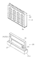
本発明に係る給電装置の好適な実施形態について、図面を用いて説明する。図1は、本発明の水素発生装置の一例を示す図であり、(a)平面図、(b)は(a)のI−I断面図である。 A preferred embodiment of a power feeding device according to the present invention will be described with reference to the drawings. 1A and 1B are diagrams showing an example of a hydrogen generator of the present invention, in which FIG. 1A is a plan view and FIG. 1B is a cross-sectional view taken along line II of FIG.
<水素発生装置>
本発明の水素発生装置30は、図1に示すように、水を収容する水収容部31と、水蒸気と反応して水素を発生する水素発生剤32と、水蒸気を流動させるファン(送風手段に相当)33と、を備える。
<Hydrogen generator>
As shown in FIG. 1, the
水収容部31には、水が収容される。水は、単に容器状の水収容ケース31aに収容されるように構成してもよいが、本発明では、使用する姿勢が変化しても一定の場所に水が留まるように、水収容ケース31a内に配置された保水材31bにより水を保持する構成であることが好ましい。
Water is stored in the
保水材としては、水が含浸可能なものであれば何れでもよいが、スポンジ、吸水性樹脂、脱脂綿、吸水性不織布、吸水紙などが好ましい。 Any water-retaining material can be used as long as it can be impregnated with water. Sponges, water-absorbing resins, absorbent cotton, water-absorbing nonwoven fabrics, water-absorbing paper, etc. are preferable.
水収容部31には、収容された水に端部34aが接し、筒状部34bを有する吸水シート(シート状部材に相当)34が設けられる。端部34aは、水収容部31に設けられたスリット31cを通って保水材31bの水に接する。吸水シート34は、吸水性を有しており、端部34aが保水材31bの水に接することで毛細管現象により吸水し、筒状部34bの全面に水が浸透する。吸水シート34の筒状部34bに浸透することで、水は蒸発しやすくなる。
The
吸水シート34としては、水を含浸可能なものであれば何れでもよいが、吸水性樹脂、脱脂綿、吸水性不織布、吸水紙などが好ましい。
The water
吸水シート34の周囲は、コの字状の断面をした整風カバー37で覆われている。整風カバー37は、水収容ケース31aに接合されている。また、整風カバー37は、ファン33と隣接する部分はファン33と接合され、ファン33と反対側の面は開放されており、ファン33から送られた風が整風カバー37の内部を通り抜ける構造となっている。
The periphery of the
ファン33は、整風カバー37とほぼ同じ幅となっており、図に破線で示す矢印のように、ファン33の羽根部から取り込んだ風を整風カバー37内に送り込むことができる。すなわち、ファン33は、整風カバー37内の吸水シート34(筒状部34b)に対して風を送ることができる。これにより、吸水シート34の表面から蒸発した水蒸気を流動させることができ、水の蒸発を促すことができる。
The
また、ファン33は、送風量を調節可能であることが好ましい。送風量を調節することで、整風カバー37内に送る風の量を調節することができる。すなわち、ファン33は、整風カバー37内の吸水シート34への送風量を調節可能であることが好ましい。吸水シート34への送風量を大きくすることで、水蒸気の発生量を多くすることができ、反対に送風量を小さくすることで、水蒸気の発生量を少なくすることもできる。
Moreover, it is preferable that the
吸水シート34から発生した水蒸気は、整風カバー37の端部37aから放出され、水蒸気供給路38を介して水素発生剤32へ供給される。水素発生剤32は、内部空間形成部36によって形成された内部空間S内に配置される。
The water vapor generated from the
<水素発生剤>
本発明における水素発生剤32は、水蒸気と反応して水素(以下、水素ガスと称することもある)を発生するものであれば何れでもよく、金属、水素化金属化合物、両者の混合物などが挙げられる。これらの水素発生剤32は、その単独粒子で使用してもよく、必要に応じて、触媒成分、アルカリ性無機化合物、凝集抑制粒子を更に含有したものを使用することができる。本発明では、水素化金属化合物を樹脂で包埋したシート状物や粉砕物が好ましい。樹脂で包埋する場合、水蒸気との反応性の観点から、多孔質体であることが好ましい。
<Hydrogen generator>
The
なお、金属としては、アルミニウム粒子、鉄粒子、マグネシウム粒子などが挙げられる。また、金属触媒としては、ニッケル、バナジウム、マンガン、チタン、銅、銀、亜鉛、ジルコニウム、コバルト、クロム、カルシウム、これらの合金等が挙げられる。 Examples of the metal include aluminum particles, iron particles, and magnesium particles. Examples of the metal catalyst include nickel, vanadium, manganese, titanium, copper, silver, zinc, zirconium, cobalt, chromium, calcium, and alloys thereof.
水素化金属化合物としては、水素化カルシウム、水素化リチウム、水素化カリウム、水素化ホウ素ナトリウム、水素化ホウ素カリウム、水素化リチウムアルミニウム、水素化アルミニウムナトリウム、又は水素化マグネシウムなどが挙げられる。これらの化合物等は、いずれも水と急激に又は爆発的に反応して水素ガスを発生することが知られており、いずれも水素化マグネシウム以上の水との反応性を示す。 Examples of the metal hydride compound include calcium hydride, lithium hydride, potassium hydride, sodium borohydride, potassium borohydride, lithium aluminum hydride, sodium aluminum hydride, and magnesium hydride. All of these compounds are known to react rapidly or explosively with water to generate hydrogen gas, and all show reactivity with water higher than magnesium hydride.
また、上記化合物以外の水素発生剤として、アルミニウム、鉄、マグネシウム、カルシウム等の金属、上記以外の金属水素錯化合物などを含有してもよい。水素化金属化合物、金属、金属水素錯化合物は、何れかを複数組み合わせて使用することもでき、また、それぞれを組み合わせて使用することも可能である。化合物を併用する場合、気泡による多孔質化を促進し易い化合物を含むことが好ましい。このような化合物としては、水素化カルシウムが特に好ましい。 Moreover, you may contain metals, such as aluminum, iron, magnesium, and calcium, metal hydrogen complex compounds other than the above, as hydrogen generating agents other than the said compound. A plurality of metal hydride compounds, metals, and metal hydride complex compounds can be used in combination, or they can be used in combination. When a compound is used in combination, it is preferable to include a compound that facilitates the formation of pores by bubbles. As such a compound, calcium hydride is particularly preferable.
粒状の水素発生剤の平均粒径は、多孔体中への分散性や反応性を制御する観点から、1〜100μmが好ましく、6〜30μmがより好ましく、8〜10μmが更に好ましい。 The average particle size of the granular hydrogen generator is preferably 1 to 100 μm, more preferably 6 to 30 μm, and still more preferably 8 to 10 μm from the viewpoint of controlling dispersibility and reactivity in the porous body.
樹脂で包埋する場合の水素発生剤の含有量は、適度な反応性とある程度の水素発生量を確保する観点から、多孔体中、10〜60重量%が好ましく、30〜50重量%が好ましい。 In the case of embedding with a resin, the content of the hydrogen generating agent is preferably 10 to 60% by weight, more preferably 30 to 50% by weight in the porous body, from the viewpoint of ensuring appropriate reactivity and a certain amount of hydrogen generation. .
用いられる樹脂としては、熱硬化性樹脂、熱可塑性樹脂、耐熱性樹脂などが挙げられるが、熱硬化性樹脂が好ましい。なお、熱可塑性樹脂としては、ポリエチレン、ポリプロピレン、ポリスチレン、アクリル樹脂、フッ素樹脂、ポリエステル、ポリアミドなどが挙げられる。また、耐熱性樹脂としては、芳香族系のポリイミド、ポリアミド、ポリエステルなどが挙げられる。 Examples of the resin used include a thermosetting resin, a thermoplastic resin, and a heat resistant resin, and a thermosetting resin is preferable. Examples of the thermoplastic resin include polyethylene, polypropylene, polystyrene, acrylic resin, fluororesin, polyester, and polyamide. Examples of the heat resistant resin include aromatic polyimide, polyamide, and polyester.
熱硬化性樹脂としては、エポキシ樹脂、不飽和ポリエステル樹脂、フェノール樹脂、アミノ樹脂、ポリウレタン樹脂、シリコーン樹脂、または熱硬化性ポリイミド樹脂等が挙げられる。なかでも、水素発生反応中に多孔質構造を適度に維持できる観点から、エポキシ樹脂が好ましい。 Examples of the thermosetting resin include epoxy resins, unsaturated polyester resins, phenol resins, amino resins, polyurethane resins, silicone resins, and thermosetting polyimide resins. Especially, an epoxy resin is preferable from a viewpoint which can maintain a porous structure moderately during hydrogen generating reaction.
樹脂が非多孔質又は開孔率の小さい多孔質である場合、水溶性樹脂や吸水性樹脂を主に使用するのが好ましい。水溶性樹脂としては、メチルセルロース、カルボキシメチルセルロース、ポリビニルアルコール、ポリエチレンオキシド等が挙げられる。吸水性樹脂としては、アクリル酸塩重合体の架橋物、ビニルアルコール−アクリル酸塩共重合体の架橋物、無水マレイン酸グラフトポリビニルアルコールの架橋物、アクリル酸塩−メタアクリル酸塩共重合体の架橋物、アクリル酸メチル−酢酸ビニル重合体のケン化物の架橋物、デンプン−アクリル酸塩グラフト共重合体の架橋物、デンプン−アクリロニトリル共重合体の加水分解物の架橋物、デンプン−アクリル酸エチルグラフト共重合体のケン化物の架橋物、カルボキシメチルセルロース架橋物等を挙げることができる。 When the resin is non-porous or porous with a low porosity, it is preferable to mainly use a water-soluble resin or a water-absorbing resin. Examples of the water-soluble resin include methyl cellulose, carboxymethyl cellulose, polyvinyl alcohol, and polyethylene oxide. Examples of water-absorbing resins include cross-linked acrylate polymers, cross-linked vinyl alcohol-acrylate copolymers, cross-linked maleic anhydride grafted polyvinyl alcohol, and acrylate-methacrylate copolymers. Cross-linked product, cross-linked product of saponified product of methyl acrylate-vinyl acetate polymer, cross-linked product of starch-acrylate graft copolymer, cross-linked product of hydrolyzate of starch-acrylonitrile copolymer, starch-ethyl acrylate Examples include a cross-linked product of a saponified graft copolymer, a cross-linked product of carboxymethyl cellulose, and the like.
樹脂の含有量は、適度な保形性とある程度の水素発生量を確保する観点から、多孔体中、30〜90重量%が好ましく、50〜70重量%が好ましい。 The content of the resin is preferably 30 to 90% by weight, more preferably 50 to 70% by weight in the porous body, from the viewpoint of securing an appropriate shape retention and a certain amount of hydrogen generation.
樹脂中には、上記の成分以外の任意成分として、触媒、充填材、発泡剤などのその他の成分を含有してもよい。触媒としては、水素発生剤用の金属触媒の他、水酸化ナトリウム、水酸化カリウム、水酸化カルシウムなどのアルカリ化合物も有効である。 The resin may contain other components such as a catalyst, a filler, and a foaming agent as optional components other than the above components. As the catalyst, an alkali compound such as sodium hydroxide, potassium hydroxide and calcium hydroxide is also effective in addition to the metal catalyst for the hydrogen generator.
発泡剤としては、未硬化の熱硬化性樹脂に相分離・分散して、熱硬化性樹脂の反応温度で気化する液体が挙げられる。また、水素発生剤と反応して水素ガスを発生させる反応液を、未硬化の熱硬化性樹脂に微量添加しておくことも可能である。このような反応液としては、水、酸水溶液、アルカリ水溶液などが挙げられる。 Examples of the foaming agent include a liquid that is phase-separated and dispersed in an uncured thermosetting resin and vaporizes at the reaction temperature of the thermosetting resin. It is also possible to add a small amount of a reaction solution that reacts with the hydrogen generator to generate hydrogen gas to the uncured thermosetting resin. Examples of such a reaction solution include water, an aqueous acid solution, and an alkaline aqueous solution.
本発明では気泡により多孔質化された構造を有する場合が好ましい。多孔質化のための気泡は、発泡剤により生成するものでもよいが、水素発生剤から発生した水素ガスであることが好ましい。 In this invention, the case where it has the structure made porous by the bubble is preferable. The bubbles for making the pores may be generated by a foaming agent, but are preferably hydrogen gas generated from a hydrogen generating agent.
つまり、多孔質体は、粒状の水素発生剤と未硬化の熱硬化性樹脂とを混合した後、これを吸水性シートに塗布し、前記水素発生剤から水素ガスを発生させつつ熱硬化性樹脂を硬化させる工程を含む製法により製造されることが好ましい。 That is, the porous body is obtained by mixing a particulate hydrogen generator and an uncured thermosetting resin, and then applying the mixture to a water absorbent sheet to generate a hydrogen gas from the hydrogen generator. It is preferable to manufacture by the manufacturing method including the process of hardening | curing.
多孔質体は、密度が0.1〜1.2g/cm3であることが好ましく、0.2〜0.9g/cm3であることがより好ましく、0.3〜0.5g/cm3であることが更に好ましい。この範囲の密度を有することで、反応液の浸透性が適度になり、取扱い性もより良好になる。このような密度は、例えば、水素ガスの発生量でコントロールすることが可能である。 The porous body is preferably a density of 0.1~1.2g / cm 3, more preferably 0.2~0.9g / cm 3, 0.3~0.5g / cm 3 More preferably. By having a density in this range, the permeability of the reaction solution becomes appropriate, and the handleability becomes better. Such a density can be controlled by, for example, the amount of hydrogen gas generated.
また、水素発生用多孔体の気泡径は、反応液の浸透性を適度に制御する観点から、直径0.1〜2mmが好ましく、直径0.5〜1mmがより好ましい。このような気泡径は、例えば、水素ガスの発生量でコントロールすることが可能である。また、気泡径や密度をコントロールするために、加圧条件下で熱硬化性樹脂の硬化を行ってもよい。 The bubble diameter of the hydrogen generating porous body is preferably 0.1 to 2 mm, more preferably 0.5 to 1 mm, from the viewpoint of appropriately controlling the permeability of the reaction solution. Such a bubble diameter can be controlled by, for example, the amount of hydrogen gas generated. In order to control the bubble diameter and density, the thermosetting resin may be cured under pressure.
水素発生剤から水素ガスを発生させるには、予め未硬化の熱硬化性樹脂に反応液を微量添加しておく方法や、未硬化の熱硬化性樹脂に含まれる反応液を利用する方法も可能であるが、硬化反応のための加熱により、水素発生剤(水素化金属化合物の場合)から水素ガスを脱離させる方法が好ましい。 In order to generate hydrogen gas from the hydrogen generator, it is possible to add a small amount of reaction liquid to the uncured thermosetting resin in advance, or to use the reaction liquid contained in the uncured thermosetting resin. However, a method of desorbing hydrogen gas from the hydrogen generator (in the case of a metal hydride compound) by heating for the curing reaction is preferable.
水素発生剤から水素ガスを脱離させる際の温度は、水素化金属化合物の種類によっても異なるが、50〜250℃が好ましく、80〜200℃がより好ましい。つまり、未硬化の熱硬化性樹脂の硬化温度として、この範囲の温度を選択することが好ましい。なお、水素ガスの発生温度と硬化温度とを変えることも可能である。 The temperature at which hydrogen gas is desorbed from the hydrogen generator varies depending on the type of metal hydride compound, but is preferably 50 to 250 ° C, more preferably 80 to 200 ° C. That is, it is preferable to select a temperature within this range as the curing temperature of the uncured thermosetting resin. It is also possible to change the generation temperature of hydrogen gas and the curing temperature.
硬化して得られるシート状多孔質体の厚みは、水等を十分かつ均一に浸透させて均一な反応を行う観点から、0.1〜10mmが好ましく、0.5〜2mmがより好ましい。 The thickness of the sheet-like porous body obtained by curing is preferably from 0.1 to 10 mm, more preferably from 0.5 to 2 mm, from the viewpoint of allowing water and the like to permeate sufficiently and uniformly to perform a uniform reaction.
本発明における水素発生剤32は、少なくとも一部が疎水性多孔質膜35aで形成されている包装材35で包囲されている。この疎水性多孔質膜35aを介して水蒸気が流入することで、水素ガスが発生する。
The
包装材35(又は水素発生剤32)は、内部空間形成部36に固定しなくてもよいが、接着等によって内部空間形成部36に固定するのが好ましい。
The packaging material 35 (or the hydrogen generating agent 32) may not be fixed to the internal
疎水性多孔質膜35aは、水を透過させずに、水蒸気及び水素ガスを透過させることができる。従って、疎水性多孔質膜35aの孔径としては、0.1〜10μmが好ましい。0.5〜5μmがより好ましい。疎水性多孔質膜35aの厚みは、十分な通気性とある程度の強度を付与する観点から、10〜500μmが好ましく、50〜200μmがより好ましい。
The hydrophobic
疎水性多孔質膜35aの材質としては、フッ素系樹脂、ポリオレフィン系樹脂、ポリエーテルサルホン、ポリスルホンなどが挙げられる。なかでも、ポリテトラフルオロエチレン等のフッ素系樹脂や、ポリプロピレン等のポリオレフィン系樹脂が好ましい。
Examples of the material of the hydrophobic
包装材35のうち、疎水性多孔質膜35a以外の部分については、上記と同様の材料からなるフィルム、シート、ケース等が使用できる。但し、本発明では、包装材35の全体が疎水性多孔質膜35aで形成されているのが好ましい。
In the
包装材35(又は疎水性多孔質膜35a)は袋状に形成するのが好ましく、内部に水素発生剤32を導入した後、開口が封止される。封止の方法としては、熱融着、接着剤による接着などが挙げられる。図示した例では、2枚の疎水性多孔質膜35aの4辺が熱融着により封止されている。
The packaging material 35 (or the hydrophobic
<発電セルの構成>
本発明の水素発生装置により発生した水素が供給されて発電を行なう燃料電池について、図面を用いて説明する。図2は、燃料電池の一例を示す図であり、(a)は斜視図、(b)は平面図、(c)は金属板の構成を示す斜視図、図3(a)は図2(b)のI−I断面図、図3(b)は同じくII−II断面図である。
<Configuration of power generation cell>
A fuel cell that generates electricity by being supplied with hydrogen generated by the hydrogen generator of the present invention will be described with reference to the drawings. 2A and 2B are diagrams showing an example of a fuel cell, in which FIG. 2A is a perspective view, FIG. 2B is a plan view, FIG. 2C is a perspective view showing a configuration of a metal plate, and FIG. FIG. 3B is a sectional view taken along the line II-II, and FIG. 3B is a sectional view taken along the line II-II.
燃料電池は、図2に示すように、複数の単位セルC1〜C4(以下、各単位セルを区別する必要がない場合は、単位セルCと表記する。)を備え、いずれかの単位セルCと他の単位セルCの導電層同士を、接続部により電気的に接続している。本実施形態では、例えば、単位セルC1の第1導電層(第1金属層4)と、それに隣接する単位セルC2の第2導電層(第2金属層5)とを電気的に接続(直列接続)する例を示すが、何れかの単位セルCと他の単位セルCとを並列接続することも可能である。その場合、何れかの単位セルCと他の単位セルCの第1導電層同士及び第2導電層同士が電気的に接続される。もちろん、並列接続と直列接続とを組み合わせることも可能である。 As shown in FIG. 2, the fuel cell includes a plurality of unit cells C1 to C4 (hereinafter, each unit cell is referred to as a unit cell C when it is not necessary to distinguish each unit cell). And the conductive layers of the other unit cells C are electrically connected to each other by a connecting portion. In the present embodiment, for example, the first conductive layer (first metal layer 4) of the unit cell C1 and the second conductive layer (second metal layer 5) of the unit cell C2 adjacent thereto are electrically connected (in series). In this example, any one unit cell C and another unit cell C can be connected in parallel. In that case, the first conductive layers and the second conductive layers of any unit cell C and the other unit cell C are electrically connected. Of course, it is also possible to combine parallel connection and series connection.
なお、接続する単位セルCの数としては、要求される電圧又は電流に応じて、設定することが可能である。本実施形態では4つの単位セルC1〜C4を接続する例を示すが、単位セルCは1つでもよく、5つ以上であってもよい。例えば、8つの単位セルを用いて、2個ずつペアで並列接続して4つのペアを作り、各ペアを直列接続することができる。この場合、4つの単位セルを直列接続する構成に対して、電圧は同じであるが電流量を2倍にすることができる。 The number of unit cells C to be connected can be set according to the required voltage or current. In the present embodiment, an example in which four unit cells C1 to C4 are connected is shown, but the number of unit cells C may be one, or five or more. For example, using eight unit cells, two pairs can be connected in parallel to form four pairs, and each pair can be connected in series. In this case, with respect to the configuration in which four unit cells are connected in series, the voltage is the same, but the amount of current can be doubled.
本実施形態における各々の単位セルCは、固体高分子電解質層1と、この固体高分子電解質層1の両側に設けられた第1電極層2及び第2電極層3と、これら電極層2,3の更に外側に各々配置された第1導電層及び第2導電層とを有する。本実施形態では、第1導電層及び第2導電層が、第1電極層2及び第2電極層3を部分的に露出させる露出部を有する第1金属層4及び第2金属層5とからなる例を示す。
Each unit cell C in the present embodiment includes a solid
なお、導電層の材質としては、金属、導電性高分子、導電性ゴム、導電性繊維、導電性ペースト、導電性塗料などが挙げられる。 Examples of the material for the conductive layer include metals, conductive polymers, conductive rubbers, conductive fibers, conductive pastes, and conductive paints.
固体高分子電解質層1としては、従来の固体高分子膜型の燃料電池に用いられるものであれば何れでもよいが、化学的安定性及び導電性の点から、超強酸であるスルホン酸基を有するパーフルオロカーボン重合体からなる陽イオン交換膜が好適に用いられる。このような陽イオン交換膜としては、ナフィオン(登録商標)が好適に用いられる。その他、例えば、ポリテトラフルオロエチレン等のフッ素樹脂からなる多孔質膜に上記ナフィオンや他のイオン伝導性物質を含浸させたものや、ポリエチレンやポリプロピレン等のポリオレフィン樹脂からなる多孔質膜や不織布に上記ナフィオンや他のイオン伝導性物質を担持させたものでもよい。
The solid
固体高分子電解質層1の厚みは、薄くするほど全体の薄型化に有効であるが、イオン伝導機能、強度、ハンドリング性などを考慮すると、10〜300μmが使用可能であるが、25〜50μmが好ましい。
The thinner the solid
電極層2,3は、固体高分子電解質層1の表面付近でアノード側およびカソード側の電極反応を生じさせるものであれば何れでもよい。なかでも、ガス拡散層としての機能を発揮して、燃料ガス、燃料液、酸化ガス及び水蒸気の供給・排出を行なうと同時に、集電の機能を発揮するものが好適に使用できる。電極層2,3としては、同一又は異なるものが使用でき、その基材には電極触媒作用を有する触媒を担持させることが好ましい。触媒は、固体高分子電解質層1と接する内面側に少なくとも担持させるのが好ましい。
The electrode layers 2 and 3 may be any as long as they cause an electrode reaction on the anode side and the cathode side near the surface of the solid
電極層2,3の電極基材としては、例えば、カーボンペーパー、カーボン繊維不織布などの繊維質カーボン、導電性高分子繊維の集合体などの電導性多孔質材が使用できる。また、固体高分子電解質層1に触媒を直接付着させたり、カーボンブラックなどの導電性粒子に担持させて固体高分子電解質層1に付着させた電極層2,3を用いることも可能である。
As the electrode substrate of the electrode layers 2 and 3, for example, conductive carbon such as carbon paper, fibrous carbon such as carbon fiber nonwoven fabric, and an aggregate of conductive polymer fibers can be used. It is also possible to use the electrode layers 2 and 3 that are attached to the solid
一般に、電極層2,3は、このような電導性多孔質材にフッ素樹脂等の撥水性物質を添加して作製されるものであって、触媒を担持させる場合、白金微粒子などの触媒とフッ素樹脂等の撥水性物質とを混合し、これに溶媒を混合して、ペースト状或いはインク状とした後、これを固体高分子電解質膜と対向すべき電極基材の片面に塗布して形成される。 In general, the electrode layers 2 and 3 are prepared by adding a water-repellent substance such as a fluororesin to such a conductive porous material. When the catalyst is supported, a catalyst such as platinum fine particles and fluorine It is formed by mixing a water-repellent substance such as a resin, mixing it with a solvent to form a paste or ink, and then applying this to one side of an electrode substrate that should face the solid polymer electrolyte membrane. The
一般に、電極層2,3や固体高分子電解質層1は、燃料電池に供給される還元ガスと酸化ガスに応じた設計がなされる。本発明では、酸化ガスとして空気が用いられると共に、還元ガスとして水素ガスを用いるのが好ましい。なお、還元ガスの代わりにメタノール等の燃料液を使用することも可能である。
In general, the electrode layers 2 and 3 and the solid
例えば、水素ガスと空気を使用する場合、空気が自然供給される側のカソード側の第2電極層3(本明細書では、アノード側を第1電極層、カソード側を第2電極層と仮定する)では、酸素と水素イオンの反応が生じて水が生成するため、かかる電極反応に応じた設計をするのが好ましい。特に、低作動温度、高電流密度及び高ガス利用率の運転条件では、特に水が生成する空気極において水蒸気の凝縮による電極多孔体の閉塞(フラッディング)現象が起こりやすい。したがって、長期にわたって燃料電池の安定な特性を得るためには、フラッディング現象が起こらないように電極の撥水性を確保することが有効である。
For example, when hydrogen gas and air are used, the
触媒としては、白金、パラジウム、ルテニウム、ロジウム、銀、ニッケル、鉄、銅、コバルト及びモリブデンから選ばれる少なくとも1種の金属か、又はその酸化物が使用でき、これらの触媒をカーボンブラック等に予め担持させたものも使用できる。 As the catalyst, at least one metal selected from platinum, palladium, ruthenium, rhodium, silver, nickel, iron, copper, cobalt and molybdenum, or an oxide thereof can be used. A supported one can also be used.
電極層2,3の厚みは、薄くするほど全体の薄型化に有効であるが、電極反応、強度、ハンドリング性などを考慮すると、1〜500μmが好ましく、100〜300μmがより好ましい。電極層2,3と固体高分子電解質層1とは、予め接着、融着、又は塗布形成等を行って積層一体化しておいてもよいが、単に積層配置されているだけでもよい。このような積層体は、膜/電極接合体(Membrane Electrode Assembly:MEA)として入手することもでき、これを使用してもよい。
The thickness of the electrode layers 2 and 3 is more effective for reducing the overall thickness as the thickness is reduced. However, in consideration of electrode reaction, strength, handling property, etc., 1 to 500 μm is preferable, and 100 to 300 μm is more preferable. The electrode layers 2 and 3 and the solid
本発明では、第1電極層2及び第2電極層3の外形が固体高分子電解質層1の外形より小さいものでもよいが、第1電極層2及び第2電極層3の外形と固体高分子電解質層1の外形とが同じであることが好ましい。電極層の外形と固体高分子電解質層の外形とが同じであると、電極板と固体高分子電解質の積層体を打ち抜いて、固体高分子電解質・電極・接合体を製造することができ、量産効果により当該接合体のコストを低減することができる。また、電極層の外周より金属層の外周が内側に形成されていることで、電極層の外周及び固体高分子電解質層の外周をより確実に封止することができる。
In the present invention, the outer shape of the
アノード側電極層2の表面にはアノード側の第1金属層4が配置され、カソード側電極層3の表面にはカソード側の第2金属層5が配置される(本明細書では、アノード側を第1金属層、カソード側を第2金属層と仮定する)。第1金属層4は、第1電極層2を部分的に露出させる露出部を有するが、本実施形態では、アノード側金属層4には燃料ガス等を供給するための開孔4aが設けられている例を示す。
A
第1金属層4の露出部は、アノード側電極層2が露出可能であれば、その個数、形状、大きさ、形成位置などは何れでもよい。アノード側金属層4の開孔4aは、例えば、規則的又はランダムに複数の円孔やスリット等を設けたり、または金属メッシュによって開孔4aを設けたり、第1金属層4を櫛形電極のような形状にしてアノード側電極層2を露出させてもよい。開孔4a部分の面積が締める割合(開孔率)は、電極との接触面積とガスの供給面積のバランスなどの観点から、10〜50%が好ましく、15〜30%がより好ましい。
The exposed portion of the
また、カソード側の第2金属層5は、第2電極層3を部分的に露出させる露出部を有するが、本実施形態では、カソード側金属層5には、空気中の酸素を供給(自然吸気)するための多数の開孔5aが設けられている例を示す。開孔5aは、カソード側電極層3が露出可能であれば、その個数、形状、大きさ、形成位置などは何れでもよい。カソード側金属層5の開孔5aは、例えば、規則的又はランダムに複数の円孔やスリット等を設けたり、または金属メッシュによって開孔5aを設けたり、第2金属層5を櫛形電極のような形状にしてカソード側電極層3を露出させてもよい。開孔5a部分の面積が締める割合(開孔率)は、電極との接触面積とガスの供給面積のバランスなどの観点から、10〜50%が好ましく、15〜30%がより好ましい。
Further, the
金属層4,5としては、電極反応に悪影響がないものであれば何れの金属も使用でき、例えばステンレス板、ニッケル、銅、銅合金などが挙げられる。但し、導電性、コスト、形状付与性、加圧のための強度などの観点から、銅、銅合金、ステンレス板などが好ましい。また、上記の金属に金メッキなどの金属メッキを施したものでもよい。
As the
なお、金属層4,5の厚みは、薄くするほど全体の薄型化に有効であるが、導電性、コスト、重量、形状付与性、加圧のための強度などを考慮すると、10〜1000μmが好ましく、50〜200μmがより好ましい。
In addition, although the thickness of the
本発明では、電極層2,3と金属層4,5とを良好に樹脂で一体化する観点から、第1電極層2の外周より、第1金属層4の外周が内側に形成されていることが好ましく、第2電極層3の外周より、第2金属層5の外周が内側に形成されていることが好ましい。なお、第1電極層2の外周より、第1金属層4の外周が外側に形成されていてもよく、第2電極層3の外周より、第2金属層5の外周が外側に形成されていてもよい。
In the present invention, from the viewpoint of satisfactorily integrating the electrode layers 2 and 3 and the
金属層4及び金属層5は、少なくとも一部が樹脂から露出することにより、その部分を電極として電気を外部に取り出すことができる。このため、樹脂成形体6に対して、金属層4及び金属層5を一部露出させた端子部を設けてもよいが、本発明では、直列接続の場合には、その両端の単位セルCの金属層4又は金属層5が、単位セルCの電極となる突出部4b,5bを備え、これが樹脂成形体6から外部に出ていることが好ましい。この突出部4b,5bは、インサート成形を行う際に、金属層4,5等(積層物L)を成形型内に保持するためにも利用できる。
When at least a part of the
金属層4及び金属層5の形成や開孔5a、4aの形成は、プレス加工(プレス打ち抜き加工)を利用して行うことができる。また、金属層4及び金属層5の突出部4b,5bには、樹脂の流動や密着性を良好にする目的で、インサート成形される部分に貫通孔を設けてもよい。更に、接続や固定を良好に行うために、突出部4b,5bの露出した部分に貫通孔を設けてもよい。
The formation of the
本発明の燃料電池は、図2に示すように、何れかの単位セルCと他の単位セルCの導電層同士を電気的に接続する接続部Jを備えているが、直列接続の場合、何れかの単位セルCの第1導電層と他の単位セルCの第2導電層とが電気的に接続される。本実施形態では、隣り合う前記単位セルCの一方の第1導電層(金属層4)と、他方の第2導電層(金属層5)と、接続部Jとが、連続する金属板(一体化した単一の金属部品)からなる金属層で形成されている例を示す。 As shown in FIG. 2, the fuel cell according to the present invention includes a connection portion J that electrically connects conductive layers of any unit cell C and other unit cells C. The first conductive layer of any unit cell C and the second conductive layer of another unit cell C are electrically connected. In the present embodiment, one first conductive layer (metal layer 4) of the adjacent unit cell C, the other second conductive layer (metal layer 5), and the connection portion J are formed from a continuous metal plate (integrated). An example in which the metal layer is formed of a single metal part).
この実施形態では、各単位セルC1〜C4が直列に接続されているため、金属層の突出部4b,5bは、それぞれ単位セルC1と単位セルC4とにだけ設けられている。
In this embodiment, since the unit cells C1 to C4 are connected in series, the protruding
第1金属層4及び第2金属層5を接続部Jを介して一体化した金属板は、隣り合う単位セルC同士を直列に接続するための部材である。第1金属層4及び第2金属層5を独立して配置する代わりに、この一体化した金属板を用いることにより、これを成形型10内に配置するだけで、単位セルC1〜C4が直列に接続された燃料電池を製造することができる(図5参照)。
The metal plate in which the
金属板は、図2(c)に示すように、相互に平行な面内に隣接して配置された第1金属層4及び第2金属層5が、同じ面内で外側に各々延設された延出部4j,5jを有しており、延出部4j,5jを段差部4sによって連結一体化してある。このような段差部は、金属板を板金加工することで作製することができる。なお、並列接続を行う場合、例えば、同じ面内に隣接して配置された第1金属層4同士(又は第2金属層5同士)が、延設された延出部により連結一体化した金属板を使用することができる。また、接続部Jは、部分的に樹脂成形体6の外部に突出した形状となっている。
As shown in FIG. 2C, the metal plate includes a
突出部4b,5bは、不図示の回路部に接続されて出力電圧として取り出すことができる。また、接続部Jについては、上記回路部に接続することで、中間的な電位のモニターを行うことができる。
The protruding
この実施形態では、接続部Jが部分的に樹脂成形体6の外部に突出する形状となっているが、接続部Jが中央に段差部を有する長方形となっていてもよい。後述のように、インサート形成する際には、積層物を成形型内に位置固定する必要があり、位置固定の際には接続部Jが部分的に樹脂成形体6の外部に突出する形状であることが好ましい。
In this embodiment, the connecting portion J has a shape that partially protrudes to the outside of the resin molded
接続部Jは、隣り合う単位セルC同士を直列に接続するものであり、第1金属層4及び第2金属層5と一体化した金属板になっている。第1金属層4及び第2金属層5を独立して配置する代わりに、この金属板を用いることにより、これを成形型内に配置するだけで、単位セルCが直列に接続された燃料電池を製造することができる。
The connecting portion J connects adjacent unit cells C in series, and is a metal plate integrated with the
<樹脂成形体>
本発明の燃料電池は、図2に示すように、以上のような単位セルC及び接続部Jをインサート成形により一体化した樹脂成形体6を備えている。樹脂成形体6は、第1電極層2及び第2電極層3に気体又は液体を供給するための供給部を有することが好ましく、この供給部は、第1金属層4又は第2金属層5の露出部に対応する位置に設けられた開孔6aであることが好ましい。
<Resin molding>
As shown in FIG. 2, the fuel cell of the present invention includes a resin molded
本実施形態では、前記第1電極層2及び第2電極層3が開孔6aから露出するように、前記第1金属層4及び第2金属層5を両側から加圧した状態で、樹脂成形体6によりインサート成形して一体化してある例を示す。
In the present embodiment, resin molding is performed in a state where the
本発明では、金属層4,5の露出部に相当する開孔4a,5aの大きさが、樹脂成形体6の開孔6aの大きさより、大きくてもよく、同じ大きさでもよく、小さくてもよい。但し、第1金属層4及び/又は第2金属層5の露出部の大きさと、開孔6aの大きさとがほぼ等しくなるように、樹脂成形体6を成形してあることが好ましい。具体的には、各々の開孔6aの面積は、各々の露出部の面積の60〜150%が好ましく、80〜130%がより好ましい。
In the present invention, the size of the
本実施形態では、金属層4,5の露出部に相当する開孔4a,5aの大きさが、樹脂成形体6の開孔6aの大きさより小さい場合の例を示す。これにより金属層4,5の開孔4a,5aの周囲に対して、樹脂成形体6の開孔6aに相当する部分を利用して、成型時に加圧することができる(図5(c)参照)。
In the present embodiment, an example in which the size of the
樹脂成形体6の材質としては、熱硬化性樹脂、熱可塑性樹脂、耐熱性樹脂などが挙げられるが、熱可塑性樹脂、熱硬化性樹脂が好ましい。なお、熱可塑性樹脂としては、ポリカーボネート樹脂、ABS樹脂、液晶ポリマー、ポリプロピレン、ポリスチレン、アクリル樹脂、フッ素樹脂、ポリエステル、ポリアミドなどが挙げられる。熱硬化性樹脂としては、エポキシ樹脂、不飽和ポリエステル樹脂、フェノール樹脂、アミノ樹脂、ポリウレタン樹脂、シリコーン樹脂、または熱硬化性ポリイミド樹脂等が挙げられる。なかでも、成形型内での樹脂の流動性、強度、溶融温度などの観点から、ポリエステル、ポリプロピレン、アクリル樹脂が好ましく、これらはアプリケーションによって選択することが可能である。
Examples of the material of the resin molded
樹脂成形体6としては、熱可塑性エラストマーやゴム等の樹脂エラストマーを用いることも可能である。その場合、他の材料にも可とう性の有るものを使用することで、燃料電池全体を可とう性にすることが可能である。
As the resin molded
樹脂成形体6の全体の厚みとしては、樹脂による一体化の強度や、金属層を加圧する圧力、薄型化などの観点から、0.3〜4mmが好ましく0.5〜2mmがより好ましい。特に、金属層を覆う部分の樹脂成形体6の厚みとしては、金属層を加圧する圧力の観点から、0.2〜1.5mmが好ましく、0.3〜1.0mmがより好ましい。
The overall thickness of the resin molded
樹脂成形体6の外形の面積としては、樹脂による一体化の強度や、金属層を加圧する圧力の観点から、固体高分子電解質層1の外形の面積の101〜200%が好ましく、150〜180%がより好ましい。
The area of the outer shape of the resin molded
樹脂成形体6の形状の一例を図4に示す。樹脂成形体6は、図4に示すように、開孔6aが形成される正面壁6b、この正面壁6bの左右両側に一体形成される側壁6c、底壁6dにより構成される。側壁6cと底壁6dが形成される後側に樹脂平板60を連結することで、扁平な函体とすることができる。樹脂平板60の材質は樹脂成形体6と同じとすることができ、両者の連結は接着やねじ等による機械的連結により行うことができる。
An example of the shape of the resin molded
なお、扁平な函体を形成するための樹脂成形体6や樹脂平板60の形状については、単位セルの個数や大きさ等に応じて、適宜変更することができる。例えば、単位セルCがインサート成形される樹脂成形体6を平板形状とし、樹脂平板60の側を側壁および底壁付きの形状としてもよい。
In addition, about the shape of the
本発明の燃料電池は、次のようにして燃料等を供給して発電させることができる。例えばカソード側は、そのまま大気開放にしておき、アノード側に設けた空間内で水素ガス等の燃料を発生させることで発電を行うことができる。また、アノード側及び/又はカソード側に対して、流路を形成するための流路形成部材を取り付けて、その流路に酸素含有ガスや燃料を供給することも可能である。流路形成部材としては、例えば流路溝と供給口と排出口を設けた板状体や、スタック型燃料電池のセパレータと類似の構造のものが使用できる。後者を使用するとスタック型燃料電池を構成することができる。 The fuel cell of the present invention can generate power by supplying fuel or the like as follows. For example, power generation can be performed by leaving the cathode side open to the atmosphere as it is and generating fuel such as hydrogen gas in a space provided on the anode side. It is also possible to attach a flow path forming member for forming a flow path to the anode side and / or the cathode side and supply an oxygen-containing gas or fuel to the flow path. As the flow path forming member, for example, a plate-like body provided with a flow path groove, a supply port, and a discharge port, or a structure similar to a separator of a stack type fuel cell can be used. When the latter is used, a stack type fuel cell can be constructed.
<燃料電池の製造方法(インサート成形)>
以上のような燃料電池は、例えば以下に示す製造方法により製造することができる。即ち、本実施形態の燃料電池の製造方法は、図5(a)〜(d)に示すように、固体高分子電解質層1、その両側に配される第1電極層2及び第2電極層3、並びにそれらの外側に配される第1導電層及び第2導電層を含む積層物Lの複数を、何れかの積層物Lと他の積層物Lの導電層同士を接続部Jにより電気的に接続した状態で成形型10内に配置する工程を含む。直列接続の場合、隣り合う積層物Lの一方の第1導電層と他方の第2導電層とが接続され、並列接続の場合、隣り合う積層物Lの一方の第1導電層と他方の第1導電層とが接続されると共に、一方の第2導電層と他方の第2導電層とが接続される。
<Fuel cell manufacturing method (insert molding)>
The fuel cell as described above can be manufactured, for example, by the following manufacturing method. That is, as shown in FIGS. 5A to 5D, the fuel cell manufacturing method of the present embodiment includes a solid
本実施形態では、第1導電層及び第2導電層が第1電極層2及び第2電極層3を部分的に露出させる露出部(例えば開孔4a,5a)を有する第1金属層4及び第2金属層5であり、その露出部が成形型10の凸部11a,12aにより閉塞した状態で成形型10内に配置する例を示す。
In this embodiment, the
単位セルCを構成する積層物Lは、その複数を同じ面内に並設してもよく、またL字型の2辺、正方形又は長方形の2辺〜4辺、三角形の2辺〜3辺などの各辺に配置してもよい。本実施形態では、2つの積層物Lを同じ面内に並設する例を示す。 A plurality of the laminates L constituting the unit cell C may be arranged side by side in the same plane, L-shaped two sides, square or rectangular two to four sides, triangular two to three sides It may be arranged on each side. In the present embodiment, an example in which two laminates L are arranged in the same plane is shown.
また、本実施形態の燃料電池の製造方法は、上記の成形型10内に樹脂を注入することで、積層物L及び前記接続部Jを一体化する樹脂成形体6を成形する工程を含む。本実施形態では、第1金属層4及び第2金属層5を両側から加圧した状態で、その成形型10内に樹脂を注入することで、第1電極層2及び第2電極層3に気体又は液体を供給するための供給部を有し、積層物Lを一体化する樹脂成形体6を成形する工程を含む例を示す。つまり、前記供給部に相当する開孔6aを除いて、積層物Lのほぼ全体を樹脂成形体6で覆う例を示す。
In addition, the method of manufacturing the fuel cell according to the present embodiment includes a step of molding the resin molded
まず、例えば、図5(a)に示すように、各々の単位セルCの形成領域の底面に、凸部11aを有する下金型11を準備する。本実施形態では、成形型10を分割構造にして分割した型部材の内面に凸部11a,12aを設け、その凸部11a,12aを第1金属層4及び第2金属層5圧接させる場合の例を示す。凸部11aは、積層物Lの下側の第1金属層4の開孔4aを閉塞させる大きさの上面を有し、各々の開孔4aに対向する位置に設けている。下金型11は、底面の周囲に側壁を有しており、側壁の内面に沿って上金型12が挿入できる。
First, as shown in FIG. 5A, for example, a
下金型11(又は上金型12)には、樹脂の注入口11bが設けられているが、注入口11bは複数設けてもよい。また、成型時の樹脂の流れを良好にするために、樹脂の小排出口を1箇所以上に設けてもよい。
The lower mold 11 (or the upper mold 12) is provided with a
更に、第1金属層4及び第2金属層5の突出部4b,5bを、成形後に樹脂成形体6から露出させるために、下金型11の側壁は分割構造になっている(図示省略)。積層物Lを成形型10内に配置する際に、下金型11の側壁に設けた矩形の切欠き部に、第1金属層4及び第2金属層5の突出部4b,5bが位置決めされ、その突出部4b,5bを型部材が押さえる構造になっている。これにより、突出部4b,5bを樹脂成形体6から露出させることができる。
Further, in order to expose the protruding
次に、例えば、図5(b)に示すように、積層物Lの複数を下金型11の底面に配置する。その際、各々の単位セルCの形成領域の底面に形成された凸部11aの上面が、各々の積層物Lの第1金属層4の開孔4aを閉塞可能な位置に配置する。
Next, for example, as shown in FIG. 5B, a plurality of laminates L are arranged on the bottom surface of the
本実施形態では、隣り合う積層物Lの一方の第1導電層と他方の第2導電層とを接続部Jにより電気的に接続した状態で成形型10内に配置する。本実施形態では、隣り合う積層物Lの一方の第1導電層(金属層4)と、他方の第2導電層(金属層5)と、接続部Jとが、連続する金属板からなる金属層で形成されている例を示す。
In the present embodiment, one first conductive layer and the other second conductive layer of the adjacent laminate L are arranged in the
積層物Lを配置する際には、各層の一部又は全部が一体化されていてもよく、一体化されていなくてもよい。また、一部が一体化されていない場合、各層を別々に配置しても、同時に配置してもよい。配置する積層物Lの構成は、前述の通りであるが、配置を行う際に、最終的な樹脂成形体6の形状の一部を予め成形した予備成形体を用いて、この予備成形体を積層物Lと共に成形型10内に配置することも可能である。
When arranging the laminate L, some or all of each layer may be integrated or may not be integrated. Moreover, when a part is not integrated, each layer may be arrange | positioned separately or may be arrange | positioned simultaneously. The configuration of the laminate L to be arranged is as described above. When the arrangement is performed, this preformed body is used by using a preformed body in which a part of the shape of the final resin molded
次に、例えば、図5(c)に示すように、下金型11の側壁の内面に沿って上金型12を挿入するが、上金型12の各々の単位セルCを形成する領域の下面には、凸部12aが設けてある。この凸部12aは、積層物Lの上側の第2金属層5の開孔5aを閉塞させる大きさの上面を有し、各々の開孔5aに対向する位置に設けている。そして、下金型11の凸部11aと上金型12凸部12aとで、金属層4,5を加圧した状態で、積層物Lを成形型10内に配置する。その際、第1金属層4及び第2金属層5の突出部4b,5bが成形型10の内部空間から外側に配置されるようにしてもよい。
Next, for example, as shown in FIG. 5 (c), the
その状態で、成形型10内に樹脂(「樹脂」には樹脂の原料液や未硬化物を含む)を注入するが、露出部(例えば開孔4a,5a)が凸部11aと凸部12aによって閉塞されているため、図5(d)に示すように、得られた成形体では第1電極層2及び第2電極層3が開孔6aから露出する。また、樹脂の注入により、固体高分子電解質層1、電極層2,3、第1金属層4及び第2金属層5を含む積層物Lの複数を、インサート成形により一体化することができる。
In this state, a resin (“resin” contains a resin raw material liquid and an uncured product) is injected into the
<燃料電池の全体構成例>
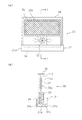
図6は、燃料電池の全体構成を示す斜視図である。単位セルC1〜C4の数は4つであり、その構成は図2で説明したものと同じである。樹脂成形体6と樹脂平板60により扁平な函体であるセル保持体Aが構成される。単位セルC1〜C4は、インサート成形により、樹脂成形体6に保持されている。このセル保持体Aの下部には水素発生装置30の水収容ケース31aが着脱自在に取り付けられる。
<Example of overall configuration of fuel cell>
FIG. 6 is a perspective view showing the overall configuration of the fuel cell. The number of unit cells C1 to C4 is four, and the configuration is the same as that described in FIG. The resin molded
図7は、燃料電池の主要な構成要素を示す分解斜視図である。セル保持体Aを構成する樹脂成形体6及び樹脂平板60には、溝6eが形成される。すなわち、セル保持体Aと水収容ケース31aの装着部分に、溝6eが形成される。溝6eは、装着部分の全周にわたって形成される。この溝6eには、防水シールが設けられる。この防水シールとしては、例えば、液体状のゴムを塗布して乾燥させるなどの構成が例として挙げられる。
FIG. 7 is an exploded perspective view showing main components of the fuel cell. A
なお、図7に示す実施形態では、水収容ケース31aの方をセル保持体Aの外周面にはめ込むような構成を採用しているが、これに限定されるものではない。すなわち、水収容ケース31aをセル保持体Aの内周面側にはめ込むような構成を採用してもよい。この場合も、同様に防水シールを用いたシール構造を採用することが好ましい。
In addition, in embodiment shown in FIG. 7, although the structure which fits the
セル保持体Aに水素発生装置30を装着した状態において、セル保持体Aの内部空間には、水素発生装置30のうち水収容ケース31a以外の部分、すなわち、包装材35(又は水素発生剤32)、ファン33、整風カバー37等が配置される。
In a state where the
<燃料電池の作用>
水素発生装置30により水素を発生させて単位セルCに供給する場合、水素発生装置30をセル保持体Aの下側から装着する。装着完了したときの断面図は図8に示される。
<Operation of fuel cell>
When hydrogen is generated by the
図8に示すように、水素発生装置30をセル保持体Aに装着した状態では、セル保持体Aに保持された単位セルCと、水素発生装置30の水素発生剤32とが対向する。水素発生剤32は、内部空間形成部36及びセル保持体A(樹脂成形体6)によって形成された内部空間S内に配置されている。内部空間Sは密閉されていてもよいが、過剰に発生した水素をリークさせるための開孔や隙間等を有していてもよい。
As shown in FIG. 8, in a state where the
保水材31bに保持された水は、吸水シート34に吸水され、吸水シート34の全面に浸透する。吸水シート34から水が蒸発して発生した水蒸気は、水蒸気供給路38を介して内部空間Sの全体に拡散して行き、疎水性多孔質膜35aを介して水素発生剤32に水蒸気が供給される。
The water held by the
本発明の水素発生装置30は、ファン33を備えており、吸水シート34から発生した水蒸気を流動させることができる。水蒸気を流動させることで、吸水シート34からの水の蒸発を促進させることができる。また、このファン33は、送風量を調節することで、水蒸気の発生量を多くしたり少なくしたりすることができる。水蒸気の発生量を制御することにより、水素発生剤32への水蒸気の供給量も制御することができる。なお、水蒸気の発生量は、吸水シート34の材質、サイズ、厚みなどによっても変化するので、これらも適宜設定する必要がある。
The
水素発生剤32は、供給された水蒸気との反応により水素を発生し、その水素が疎水性多孔質膜35aを介して内部空間Sに放出される。この水素が、単位セルCの一方の表面から供給され、他方の表面から空気中の酸素が供給されるため、各々の電極で電極反応が生じて発電を行うことができる。発電は、水蒸気の発生が終了するか、水素発生剤が消費されるまで継続して終了する。
The
なお、ファン33は、燃料電池で発電された電力によって作動するが、燃料電池による発電の開始時には、電力が供給されず作動することができない。ファン33が作動されないと、吸水シート34から発生した水蒸気は、内部空間Sの全体に徐々に拡散して行き、水素発生剤32に供給される。この構成であれば、燃料電池による発電はゆっくりと開始され、立ち上がりが良くない。
The
そこで、本発明に係る給電装置は、燃料電池による発電初期にファン33に電力を供給する補助電池(不図示)を備えることが好ましい。補助電池の電力によってファン33を作動させることで、燃料電池による発電の開始時に強制的に水蒸気を水素発生剤32に供給し、速やかに発電を開始することができる。ただし、補助電池は、必ずしも必要ではない。
Therefore, the power supply device according to the present invention preferably includes an auxiliary battery (not shown) that supplies power to the
また、本発明の水素発生装置30において、水蒸気供給路38に逆止弁(不図示)を設けていることが好ましい。水蒸気供給路38に逆止弁を設けることで、水蒸気が水蒸気供給路38を逆流して水収容部31に戻ることを防止することができる。水蒸気の逆流を防止することで、水素発生剤32に供給される水蒸気の量を制御し、水素の発生量を正確に制御することができる。
In the
<水素発生装置の別実施形態>
前述の実施形態では、ファン33が吸水シート34に対して直接送風し、水蒸気を流動させる例を示したが、ファン33は、吸水シート34に対して直接送風しなくてもよい。具体的には、図9のようにファン33を配置してもよい。この例では、ファン33は、吸水シート34から自然に発生した水蒸気を空間内で流動させるのみで、吸水シート34に直接風を当てることはない。このような構成であっても、水蒸気を流動させることで、吸水シート34からの水の蒸発を促進させ、水蒸気の発生量を制御することができる。
<Another embodiment of the hydrogen generator>
In the above-described embodiment, the example in which the
また、前述の実施形態では、吸水シート34が筒状部34bを有する例を示したが、給水シート34はこの形状に限定されるものではない。すなわち、給水シート34の形状およびファン33の配置を図10に示すようにしてもよい。図10は水素発生装置の別実施形態を示しており、(a)は斜視図、(b)は(a)のI−I断面図である。なお、図10では、水素発生剤32は省略しており、図示していない。この例では、ファン33は水収容部31内の中央に配置され、その周囲を取り囲むように保水材31bが配置される。図10に示すように、メッシュ状をした吸水シート34は、ファン33の上部を覆い、その4辺の端部34aが保水材31bに接するように構成される。吸水シート34は、吸水性を有しており、端部34aが保水材31bの水に接することで吸水し、メッシュ状の吸水シート34の全面に水が浸透する。この構成によれば、ファン33は、メッシュ状の吸水シート34の下方から送風するので、吸水シート34からの水の蒸発を促進することができる。
Moreover, although the
また、前述の実施形態では、吸水シート34から発生した水蒸気をファン33で流動させることで水蒸気の発生量を制御する構成する例を示したが、本発明では、例えば、超音波発振子などを利用して水収容部31から発生した霧をファンで流動させ、霧が気化した水蒸気の量を制御する構成でもよい。
In the above-described embodiment, an example is shown in which the amount of water vapor generated is controlled by causing the water vapor generated from the water
<発電セルの別実施形態>
(1)前述の実施形態では、直列接続した複数の単位セルにより発電セルを構成する例を示したが、本発明では、単数の単位セルにより発電セルを構成してもよい。また、複数の単位セルを並列に接続してもよい。
<Another embodiment of the power generation cell>
(1) In the above-described embodiment, an example in which a power generation cell is configured by a plurality of unit cells connected in series has been described. However, in the present invention, a power generation cell may be configured by a single unit cell. A plurality of unit cells may be connected in parallel.
(2)前述の実施形態では、固体高分子電解質層1、電極層2,3、第1金属層4及び第2金属層5をインサート形成により一体化して単位セルCを形成する例を示したが、第1金属層4と第2金属層5とをより面積の広いものにして、絶縁材を介在させつつ両者の周囲部分をカシメにより封止した構造の単位セルCを用いてもよい。このようなカシメ構造の単位セルCについては、例えば、国際公開公報WO2005/050766号公報に開示されており、カシメ封止を行うための製造方法及び製造設備については、例えば、特開2006−86041号公報に開示される技術を用いることができる。
(2) In the above-described embodiment, an example in which the unit cell C is formed by integrating the solid
このようなカシメ構造の単位セルCは、必要によりその複数を電気的に接続した後に、インサート形成等により、セル保持体と一体化されて、板状の発電セルを形成することができる。板状の発電セルは、図2に示すものと同様にして本発明に使用することができる。 The unit cells C having such a caulking structure can be integrated with a cell holder by insert formation or the like after electrically connecting a plurality of the unit cells C as necessary to form a plate-shaped power generation cell. The plate-shaped power generation cell can be used in the present invention in the same manner as shown in FIG.
<アンモニア除去剤について>
本発明では、水素発生剤32より発生した水素から、不純物であるアンモニアを除去するために、内部空間Sにアンモニア除去剤を設けてもよい。具体的には、シート状のアンモニア除去剤を包装された水素発生剤32と重ねて配置することができる。このようなアンモニア除去剤は、シート状に形成されたものが市販されているが、粒状の吸着剤等を通気性の袋に収容したものを使用することも可能である。
<About ammonia remover>
In the present invention, an ammonia removing agent may be provided in the internal space S in order to remove ammonia as an impurity from hydrogen generated from the
アンモニア除去剤としては、例えば、水素中のアンモニアを吸着除去する吸着剤(吸着・分解や反応吸着などの化学吸着を含む)、アンモニアを溶解除去する吸収剤、アンモニアを反応により除去する反応剤、アンモニアを分解(加熱分解・触媒反応分解等)により除去する分解手段、などが挙げられるが、アンモニアを物理吸着又は化学吸着により除去する吸着剤を備えることが好ましい。 As the ammonia removing agent, for example, an adsorbent that adsorbs and removes ammonia in hydrogen (including chemical adsorption such as adsorption / decomposition and reaction adsorption), an absorbent that dissolves and removes ammonia, a reactant that removes ammonia by reaction, Examples include decomposition means for removing ammonia by decomposition (thermal decomposition, catalytic reaction decomposition, etc.), and it is preferable to provide an adsorbent that removes ammonia by physical adsorption or chemical adsorption.
<回路構成など>
本発明の燃料電池は、更に昇圧や電流制御のための電子回路を設けてもよい。例えば、各単位セルCによる出力電圧は、DC−DCコンバータ(昇圧回路に相当)により所定の電圧にまで昇圧するのが好ましい。回路部には、安定化回路などが備えられており、適切な出力電圧や出力電流を供給できるように制御がなされる。更に、コンバータの下流側に付加される回路部を介して、電源供給端子から外部機器、携帯電話などに電源供給がされる。
<Circuit configuration>
The fuel cell of the present invention may further include an electronic circuit for boosting and current control. For example, the output voltage of each unit cell C is preferably boosted to a predetermined voltage by a DC-DC converter (corresponding to a booster circuit). The circuit unit is provided with a stabilization circuit and the like, and is controlled so that an appropriate output voltage and output current can be supplied. Further, power is supplied from the power supply terminal to an external device, a mobile phone, or the like via a circuit unit added on the downstream side of the converter.
以下、本発明の水素発生装置の構成と効果を具体的に示す実施例等について説明する。 Hereinafter, examples and the like specifically showing the configuration and effects of the hydrogen generator of the present invention will be described.
(実施例1)
上記の実施形態で説明した、吸水シート34の筒状部34bに送風することのできるファン33を備える水素発生装置30を用いて、水蒸気の発生量(蒸発量)を調べた。また、発生した水蒸気を水素発生剤32に供給し、水素の発生量を調べた。
Example 1
Using the
水素発生剤32としては、水素化カルシウムを樹脂で包埋した粉砕物1.2gを用いた。なお、以下の比較例においても、同様の水素発生剤32を用いた。
As the
(比較例1)
比較例1では、上記の実施例1と同様の水素発生装置30を用いて、水蒸気の発生量を調べた。ただし、比較例1では、ファン33を作動させず、吸水シート34から自然に水蒸気を発生させた。
(Comparative Example 1)
In Comparative Example 1, the amount of water vapor generated was examined using the
(実施例2)
実施例2の水素発生装置は、実施例1と同様のファン33を備えるが、ファン33の配置を変化させた。具体的には、図9で示した水素発生装置を用い、ファン33は、吸水シート34に対して直接送風することなく、吸水シート34から自然に発生した水蒸気を空間内で流動させる役割のみを果たすようにした。このときの水素の発生量を調べた。
(Example 2)
The hydrogen generator of Example 2 includes the
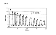
実施例1と比較例1における時間経過に伴う水蒸気発生量の結果を図11に示す。図11(a)は、縦軸が蒸発量(cc)、横軸が時間(分)であり、図11(b)では、縦軸が総蒸発量(cc)、横軸が時間(分)である。実施例1では、ファンを連続的に作動させ、比較例1では、ファンを停止させたままとした。この結果から、ファンを作動させることで水蒸気の発生量は大きく増加し、ファンは水の蒸発を促進させる効果があることが分かる。 The results of the amount of water vapor generated with the passage of time in Example 1 and Comparative Example 1 are shown in FIG. In FIG. 11A, the vertical axis is the evaporation amount (cc), the horizontal axis is the time (minute), and in FIG. 11B, the vertical axis is the total evaporation amount (cc), and the horizontal axis is the time (minute). It is. In Example 1, the fan was operated continuously, and in Comparative Example 1, the fan was kept stopped. From this result, it can be seen that the amount of water vapor generated is greatly increased by operating the fan, and the fan has the effect of promoting the evaporation of water.
実施例1における水素発生量の結果を図12に示す。実施例2における水素発生量の結果を図13に示す。なお、図12,図13では、水素発生量を流速(cc/min)として表しており、縦軸が流速、横軸が時間(分)である。実施例1および実施例2では、図12および図13に示すように、ファンのオンオフを繰り返し行なった。これらの結果から、実施例1、実施例2ともに、ファンをオンにすることで水素発生量が増加することが分かる。すなわち、ファンで水蒸気を流動させることで、水の蒸発を促進させ、水蒸気の発生量を制御し、その結果、水素発生量を制御することができることが分かる。また、実施例1の水素発生装置は、実施例2の水素発生装置に比べ、水素発生量が多いことが分かる。 The result of the hydrogen generation amount in Example 1 is shown in FIG. The result of the hydrogen generation amount in Example 2 is shown in FIG. 12 and 13, the amount of hydrogen generation is expressed as a flow rate (cc / min), the vertical axis is the flow rate, and the horizontal axis is the time (minutes). In Example 1 and Example 2, as shown in FIGS. 12 and 13, the fan was repeatedly turned on and off. From these results, it can be seen that in both Example 1 and Example 2, the amount of hydrogen generated increases by turning on the fan. That is, it is understood that by causing the steam to flow with the fan, the evaporation of water is promoted and the amount of water vapor generated is controlled, and as a result, the amount of hydrogen generated can be controlled. It can also be seen that the hydrogen generator of Example 1 has a larger amount of hydrogen generation than the hydrogen generator of Example 2.
1 固体高分子電解質層
2 アノード側電極層
3 カソード側電極層
4 アノード側金属層
5 カソード側金属層
6 樹脂成形体
30 水素発生装置
31 水収容部
31a 水収容ケース
31b 保水材
32 水素発生剤
33 ファン
34 吸水シート
34a 端部
34b 筒状部
37 整風カバー
38 水蒸気供給路
60 樹脂平板
C 単位セル
DESCRIPTION OF
Claims (7)
水を収容する水収容部と、
この水が気化した水蒸気と反応して水素を発生する水素発生剤と、
前記水蒸気を流動させる送風手段と、を備える水素発生装置。 A hydrogen generator for generating hydrogen to be supplied to a fuel cell,
A water storage section for storing water;
A hydrogen generating agent that reacts with vaporized water vapor to generate hydrogen;
A hydrogen generator comprising: a blowing means for causing the water vapor to flow.
前記送風手段は、前記シート状部材に送風する請求項1又は2に記載の水素発生装置。 The water storage portion is provided with a water-absorbing sheet-like member that is partially in contact with the stored water,
The hydrogen generator according to claim 1, wherein the blowing unit blows air to the sheet-like member.
前記送風手段は、前記筒状部内に送風する請求項3に記載の水素発生装置。 The sheet-like member has a cylindrical portion,
The hydrogen generating apparatus according to claim 3, wherein the blowing unit blows air into the cylindrical portion.
この水素発生装置により発生した水素が供給されて発電を行なう燃料電池と、
この燃料電池による発電初期に前記送風手段に電力を供給する補助電池と、を備える給電装置。 A hydrogen generator according to any one of claims 1 to 5;
A fuel cell that is supplied with hydrogen generated by the hydrogen generator and generates power;
An auxiliary battery that supplies power to the blowing means at the initial stage of power generation by the fuel cell.
送風により水からの水蒸気の発生を促進しながら、水素発生剤と前記水蒸気とを反応させて水素を発生させる水素発生方法。
A hydrogen generation method for generating hydrogen to be supplied to a fuel cell,
A hydrogen generation method for generating hydrogen by reacting a hydrogen generating agent with the water vapor while promoting generation of water vapor from water by blowing air.
Priority Applications (1)
| Application Number | Priority Date | Filing Date | Title |
|---|---|---|---|
| JP2008265423A JP2010097721A (en) | 2008-10-14 | 2008-10-14 | Hydrogen generator, hydrogen generation method, and power feeding device |
Applications Claiming Priority (1)
| Application Number | Priority Date | Filing Date | Title |
|---|---|---|---|
| JP2008265423A JP2010097721A (en) | 2008-10-14 | 2008-10-14 | Hydrogen generator, hydrogen generation method, and power feeding device |
Publications (1)
| Publication Number | Publication Date |
|---|---|
| JP2010097721A true JP2010097721A (en) | 2010-04-30 |
Family
ID=42259269
Family Applications (1)
| Application Number | Title | Priority Date | Filing Date |
|---|---|---|---|
| JP2008265423A Withdrawn JP2010097721A (en) | 2008-10-14 | 2008-10-14 | Hydrogen generator, hydrogen generation method, and power feeding device |
Country Status (1)
| Country | Link |
|---|---|
| JP (1) | JP2010097721A (en) |
Cited By (4)
| Publication number | Priority date | Publication date | Assignee | Title |
|---|---|---|---|---|
| JP2013120639A (en) * | 2011-12-06 | 2013-06-17 | Konica Minolta Inc | Fuel cell system |
| JP2013254744A (en) * | 2009-12-14 | 2013-12-19 | Industrial Technology Research Institute | Power supply device |
| JP2015086129A (en) * | 2013-10-30 | 2015-05-07 | 中強光電股▲ふん▼有限公司 | Fuel treatment apparatus and device for high purification of hydrogen gas |
| JP2021512836A (en) * | 2018-02-13 | 2021-05-20 | “アポロン ソラー” | Portable equipment for producing hydrogen and its use |
-
2008
- 2008-10-14 JP JP2008265423A patent/JP2010097721A/en not_active Withdrawn
Cited By (4)
| Publication number | Priority date | Publication date | Assignee | Title |
|---|---|---|---|---|
| JP2013254744A (en) * | 2009-12-14 | 2013-12-19 | Industrial Technology Research Institute | Power supply device |
| JP2013120639A (en) * | 2011-12-06 | 2013-06-17 | Konica Minolta Inc | Fuel cell system |
| JP2015086129A (en) * | 2013-10-30 | 2015-05-07 | 中強光電股▲ふん▼有限公司 | Fuel treatment apparatus and device for high purification of hydrogen gas |
| JP2021512836A (en) * | 2018-02-13 | 2021-05-20 | “アポロン ソラー” | Portable equipment for producing hydrogen and its use |
Similar Documents
| Publication | Publication Date | Title |
|---|---|---|
| JP5218945B2 (en) | Fuel cell and manufacturing method thereof | |
| JP2004536419A (en) | System with fuel cell membrane and integrated gas separation | |
| WO2006101132A1 (en) | Fuel cell | |
| US7297430B2 (en) | Anode diffusion layer for a direct oxidation fuel cell | |
| JP5201398B2 (en) | Fuel cell | |
| JP2010097721A (en) | Hydrogen generator, hydrogen generation method, and power feeding device | |
| WO2007080763A1 (en) | Solid polymer fuel cell | |
| JP6019300B2 (en) | Power generator | |
| JPWO2008023632A1 (en) | Membrane electrode assembly, method for producing the same, and fuel cell | |
| WO2007110941A1 (en) | Fuel cell | |
| JP6040389B2 (en) | Fuel cell system | |
| JP4945914B2 (en) | Fuel cell | |
| WO2007034756A1 (en) | Fuel cell | |
| JP5990798B2 (en) | Power generator | |
| JP2009231195A (en) | Fuel cell and electronic device | |
| US20090263688A1 (en) | Fuel cell | |
| JP5631806B2 (en) | Power generation apparatus and power generation method | |
| JP2009120441A (en) | Power generating apparatus and power generation method | |
| JP2009110904A (en) | Fuel cell | |
| JP2010027594A (en) | Fuel cell | |
| JP4843906B2 (en) | Fuel cell system and equipment | |
| JP6085759B2 (en) | Power generator | |
| KR101093709B1 (en) | Fuel cell system | |
| JP2009004170A (en) | Fuel cell | |
| KR20070079529A (en) | Cell pack of direct methanol fuel cell |
Legal Events
| Date | Code | Title | Description |
|---|---|---|---|
| A300 | Withdrawal of application because of no request for examination |
Free format text: JAPANESE INTERMEDIATE CODE: A300 Effective date: 20120110 |