JP2010096352A - Assembly for operating shift fork of transmission - Google Patents
Assembly for operating shift fork of transmission Download PDFInfo
- Publication number
- JP2010096352A JP2010096352A JP2009241288A JP2009241288A JP2010096352A JP 2010096352 A JP2010096352 A JP 2010096352A JP 2009241288 A JP2009241288 A JP 2009241288A JP 2009241288 A JP2009241288 A JP 2009241288A JP 2010096352 A JP2010096352 A JP 2010096352A
- Authority
- JP
- Japan
- Prior art keywords
- spring
- shift fork
- shift
- assembly
- assembly according
- Prior art date
- Legal status (The legal status is an assumption and is not a legal conclusion. Google has not performed a legal analysis and makes no representation as to the accuracy of the status listed.)
- Granted
Links
Images


Classifications
-
- F—MECHANICAL ENGINEERING; LIGHTING; HEATING; WEAPONS; BLASTING
- F16—ENGINEERING ELEMENTS AND UNITS; GENERAL MEASURES FOR PRODUCING AND MAINTAINING EFFECTIVE FUNCTIONING OF MACHINES OR INSTALLATIONS; THERMAL INSULATION IN GENERAL
- F16H—GEARING
- F16H63/00—Control outputs from the control unit to change-speed- or reversing-gearings for conveying rotary motion or to other devices than the final output mechanism
- F16H63/02—Final output mechanisms therefor; Actuating means for the final output mechanisms
- F16H63/30—Constructional features of the final output mechanisms
- F16H63/32—Gear shift yokes, e.g. shift forks
-
- F—MECHANICAL ENGINEERING; LIGHTING; HEATING; WEAPONS; BLASTING
- F16—ENGINEERING ELEMENTS AND UNITS; GENERAL MEASURES FOR PRODUCING AND MAINTAINING EFFECTIVE FUNCTIONING OF MACHINES OR INSTALLATIONS; THERMAL INSULATION IN GENERAL
- F16H—GEARING
- F16H63/00—Control outputs from the control unit to change-speed- or reversing-gearings for conveying rotary motion or to other devices than the final output mechanism
- F16H63/02—Final output mechanisms therefor; Actuating means for the final output mechanisms
- F16H63/30—Constructional features of the final output mechanisms
- F16H2063/3089—Spring assisted shift, e.g. springs for accumulating energy of shift movement and release it when clutch teeth are aligned
-
- F—MECHANICAL ENGINEERING; LIGHTING; HEATING; WEAPONS; BLASTING
- F16—ENGINEERING ELEMENTS AND UNITS; GENERAL MEASURES FOR PRODUCING AND MAINTAINING EFFECTIVE FUNCTIONING OF MACHINES OR INSTALLATIONS; THERMAL INSULATION IN GENERAL
- F16H—GEARING
- F16H63/00—Control outputs from the control unit to change-speed- or reversing-gearings for conveying rotary motion or to other devices than the final output mechanism
- F16H63/02—Final output mechanisms therefor; Actuating means for the final output mechanisms
- F16H63/30—Constructional features of the final output mechanisms
- F16H63/32—Gear shift yokes, e.g. shift forks
- F16H2063/321—Gear shift yokes, e.g. shift forks characterised by the interface between fork body and shift rod, e.g. fixing means, bushes, cams or pins
-
- F—MECHANICAL ENGINEERING; LIGHTING; HEATING; WEAPONS; BLASTING
- F16—ENGINEERING ELEMENTS AND UNITS; GENERAL MEASURES FOR PRODUCING AND MAINTAINING EFFECTIVE FUNCTIONING OF MACHINES OR INSTALLATIONS; THERMAL INSULATION IN GENERAL
- F16H—GEARING
- F16H63/00—Control outputs from the control unit to change-speed- or reversing-gearings for conveying rotary motion or to other devices than the final output mechanism
- F16H63/02—Final output mechanisms therefor; Actuating means for the final output mechanisms
- F16H63/08—Multiple final output mechanisms being moved by a single common final actuating mechanism
- F16H63/16—Multiple final output mechanisms being moved by a single common final actuating mechanism the final output mechanisms being successively actuated by progressive movement of the final actuating mechanism
- F16H63/18—Multiple final output mechanisms being moved by a single common final actuating mechanism the final output mechanisms being successively actuated by progressive movement of the final actuating mechanism the final actuating mechanism comprising cams
-
- Y—GENERAL TAGGING OF NEW TECHNOLOGICAL DEVELOPMENTS; GENERAL TAGGING OF CROSS-SECTIONAL TECHNOLOGIES SPANNING OVER SEVERAL SECTIONS OF THE IPC; TECHNICAL SUBJECTS COVERED BY FORMER USPC CROSS-REFERENCE ART COLLECTIONS [XRACs] AND DIGESTS
- Y10—TECHNICAL SUBJECTS COVERED BY FORMER USPC
- Y10T—TECHNICAL SUBJECTS COVERED BY FORMER US CLASSIFICATION
- Y10T74/00—Machine element or mechanism
- Y10T74/20—Control lever and linkage systems
- Y10T74/20012—Multiple controlled elements
- Y10T74/20018—Transmission control
- Y10T74/20177—Particular element [e.g., shift fork, template, etc.]
Abstract
Description
本発明は請求項1の上位概念(「おいて」書き)で詳しく定義された種類の、車両のトランスミッションの少なくとも1個のシフトフォークの操作のためのアセンブリに関する。
The invention relates to an assembly for the operation of at least one shift fork of a transmission of a vehicle of the kind defined in detail in the superordinate concept of
トランスミッションで種々の速度レンジを切換えるためのばね付きシフトフォークアセンブリを備えたシフトシステムが、例えば、刊行物米国特許公報US6619153B2により公知である。そのためにシフトレールに軸方向移動可能に取り付けられたシフトフォークが操作ユニットによって操作される。トランスミッションで所望の速度レンジをセットするためにシフトフォークと連動するスリーブが、シフトフォークの軸方向移動によって移動させられる。シフトフォークは圧縮ばねとして形成されたコイルばねを介してシフトレールに取り付けられる。こうしてシフトフォークのシフト運動の双方向に対してばねの介在が実現される。 A shift system with a spring-loaded shift fork assembly for switching various speed ranges in a transmission is known, for example, from the publication US Pat. No. 6,619,153 B2. For this purpose, a shift fork attached to the shift rail so as to be movable in the axial direction is operated by the operation unit. A sleeve associated with the shift fork is moved by the axial movement of the shift fork to set the desired speed range in the transmission. The shift fork is attached to the shift rail via a coil spring formed as a compression spring. In this way, the spring is interposed in both directions of the shift movement of the shift fork.
また車両のドライブトレインのためのシフトフォークを操作する同様のアセンブリが、刊行物、米国特許公報US4529080により公知である。このアセンブリでもシフトフォークは圧縮ばねを介してシフトレールに取り付けられている。こうして同じくシフトフォークのシフト運動の双方向に対してばねの介在が実現される。 A similar assembly for operating a shift fork for a vehicle drive train is also known from the publication US Pat. No. 4,529,080. In this assembly as well, the shift fork is attached to the shift rail via a compression spring. In this way, the spring is also provided for both shift movements of the shift fork.
2つの公知のアセンブリの根底には、圧縮ばねとりわけコイルスプリングを使用しているため、双方向についてばねの介在のあるばねマウント(取付)構造を実現するために大きな軸方向取付けスペースが必要であるという欠点がある。このため、不利なことに、アセンブリが取り付けられるトランスミッションの取付けスペースも増加してしまう。 Since the two known assemblies use compression springs, especially coil springs, a large axial mounting space is required to realize a spring-mounted structure with a spring interposed in both directions. There is a drawback. This disadvantageously increases the mounting space for the transmission to which the assembly is mounted.
そこで本発明の根底にあるのは、車両トランスミッションの少なくとも1個のシフトフォークの操作のための冒頭に述べた類別のアセンブリにおいて、シフトフォークに対するばねの作用はかわらず、しかも、ごく僅かな軸方向取付けスペースしか必要としないアセンブリを提案するという課題である。 The basis of the present invention is therefore that in the class of assemblies described at the outset for the operation of at least one shift fork of a vehicle transmission, the spring does not act on the shift fork, but with very little axial direction. The problem is to propose an assembly that requires only mounting space.
この課題は本発明に基づき請求項1の特徴によって解決される。その他の有利な実施態様が従属請求項及び図面で明かである。
This problem is solved according to the invention by the features of
そこで、少なくとも軸方向に向けられたシフト運動の遂行のために、シフトレールに取り付けられたシフトフォークを操作する少なくとも1個の操作ユニットを有し、シフトフォークの双方向又は単方向の運動に対してばねが介在するばねマウント(取付)構造(spring mounting)が設けられた、車両のトランスミッションの少なくとも1個のシフトフォークの操作のためのアセンブリが提案される。本発明によれば、少なくとも1個の撓みばね(flexible spring)を用いたシフトフォークの双方向又は単方向運動のためのばねマウント構造が設けられる。ここでいう「撓みばね」は、典型的には、実質的に曲げ応力のみを受け、実質的に捻り応力を受けないようなものである。 Therefore, at least one operation unit for operating the shift fork attached to the shift rail is required for performing the shift motion directed at least in the axial direction. An assembly is proposed for the operation of at least one shift fork of a vehicle transmission, provided with a spring mounting with a spring interposed. According to the present invention, a spring mount structure is provided for bidirectional or unidirectional movement of a shift fork using at least one flexible spring. The “flexure spring” here is typically such that it is substantially only subjected to bending stress and not substantially torsional stress.
使用される撓みばねは、例えば、レッグスプリング(leg spring、脚付きばね)、ばねクランプ(spring clamp)等として形成することができ、先行技術で使用される圧縮ばねとりわけコイルスプリングに比して、シフト運動を操作ユニットからシフトフォークへ弾力的に伝達するために、シフトフォークに余計な軸方向取付けスペースが必要でないという大きな利点を有する。この軸方向取付けスペースの利点を実現する他のばね部材等を使用することもできる。 The deflection spring used can be formed, for example, as a leg spring, a spring clamp or the like, compared to compression springs, especially coil springs, used in the prior art, In order to elastically transmit the shift movement from the operating unit to the shift fork, the shift fork has the great advantage that no extra axial mounting space is required. Other spring members or the like that realize the advantages of this axial mounting space can also be used.
発明の有利な実施形態に関連して、シフトレールをほぼ横切って整列された(或いはシフトレール軸線方向に対してほぼ垂直方向に延びる)支持ピンの周りに回転しうるように、レバープレート等をシフトフォークに取り付け、その際レバープレートは撓みばねによってシフトフォークに予圧(プリロード)されており、操作ユニットからレバープレートに伝達されるシフト運動が撓みばねを介してシフトフォークに伝達されるようにすることができる。操作ユニットからシフトフォークへのシフト運動の同様な伝達を実現する別の構成も可能である。 In connection with an advantageous embodiment of the invention, a lever plate or the like may be rotated so as to be able to rotate around a support pin that is aligned substantially across the shift rail (or extends substantially perpendicular to the shift rail axis). At this time, the lever plate is preloaded on the shift fork by a deflection spring, so that the shift motion transmitted from the operation unit to the lever plate is transmitted to the shift fork via the deflection spring. be able to. Other configurations are also possible which realize a similar transmission of the shift movement from the operating unit to the shift fork.
発明の実施態様によれば、撓みばね等によるレバープレートからシフトフォークへの力の伝達を実現するために、撓みばねの脚部がそれぞれレバープレートの駆動ピン等に接するようにすることができる。撓みばねとレバープレートの間の他の連動機構を使用することもできる。 According to the embodiment of the invention, in order to realize the transmission of force from the lever plate to the shift fork by the bending spring or the like, the leg portions of the bending spring can be in contact with the driving pin or the like of the lever plate, respectively. Other interlocking mechanisms between the flexure spring and the lever plate can also be used.
発明の好ましい改良によれば、操作ユニットがシフトシャフトに固定されたガイドプレート等を備え、ガイドプレートは少なくとも1個のスロットを介してレバープレートの少なくとも1個の操作ピンと連動する。この操作方式によって操作ユニットからシフトフォークへの力の伝達がなるべく取付けスペースをとらずに実現されるから、本発明に基づくアセンブリを設けることによって、トランスミッションを短くコンパクトに構成することもできる。 According to a preferred improvement of the invention, the operating unit comprises a guide plate or the like fixed to the shift shaft, and the guide plate is interlocked with at least one operating pin of the lever plate via at least one slot. Since transmission of force from the operation unit to the shift fork can be realized with as little space as possible by this operation method, the transmission can be configured to be short and compact by providing the assembly according to the present invention.
例えば複数のスロットを設けることによって、操作ユニットのガイドプレートで複数のシフトフォークを操作することがとりわけ考えられる。各スロットは、ガイドプレートの回転運動からシフトフォークの軸方向運動が生じるように形成することができる。これは例えばスロットの折れ曲がった形によって可能になる。しかしスロットの別の形も考えられる。2個のシフトフォークが操作ユニットのガイドプレートにより操作される場合は、例えば2つのシフトフォークの一方を双方向又は単方向に有効な(ばねが関与する)ばねマウント構造を備えたシフトフォークとして、2つのシフトフォークの他方をばねマウント構造を有しないシフトフォークとして形成することが可能である。ばねマウント構造を備えたシフトフォークを用いることにより、とりわけシフトスリーブ又はかみ合いクラッチがシンクロナイザなしで操作され、一方で、ばねマウント構造を有しないシフトフォークによってとりわけシンクロナイザ及び/又はロック式シンクロナイザを有するシフトスリーブ又はかみ合いクラッチが操作されるようにすることができる。操作される2つのシフトフォークを双方向又は単方向に有効なばねマウント構造を備えたシフトフォークとして形成するか、もしくは、2つのシフトフォークの一方を双方向に有効なばねマウント構造を備えたシフトフォークとするとともに2つのシフトフォークの他方を単方向に有効なばねマウント構造を備えたシフトフォークとして形成することももちろん可能である。 It is especially conceivable to operate a plurality of shift forks with a guide plate of the operating unit, for example by providing a plurality of slots. Each slot can be formed such that the axial movement of the shift fork results from the rotational movement of the guide plate. This is possible, for example, by the bent shape of the slot. However, other forms of slots are possible. When two shift forks are operated by the guide plate of the operation unit, for example, one of the two shift forks is a shift fork having a spring mount structure that is effective in both directions or in one direction (with a spring involved) It is possible to form the other of the two shift forks as a shift fork without a spring mount structure. By using a shift fork with a spring mounting structure, in particular the shift sleeve or the meshing clutch can be operated without a synchronizer, while a shift fork without a spring mounting structure has a synchronizer and / or a locking synchronizer in particular. Alternatively, the meshing clutch can be operated. Two shift forks to be operated are formed as a shift fork with a spring mount structure effective in both directions or in one direction, or one of the two shift forks is shifted with a spring mount structure effective in both directions Of course, it is possible to form a fork and a shift fork having a spring mount structure effective in one direction in the other of the two shift forks.
本発明に基づき提案されたアセンブリは任意のトランスミッションで使用することができる。例えばトランスファギヤで超低速ギヤの連結又は切断のために、シフトフォークを使用して当該のシフトスリーブ等を操作することができる。 The assembly proposed according to the invention can be used in any transmission. For example, a shift fork can be used to operate the shift sleeve or the like in order to connect or disconnect an ultra-low speed gear with a transfer gear.
次に図面に基づき発明を詳述する。 Next, the invention will be described in detail with reference to the drawings.
図1にシフトフォーク1、2の操作のためのアセンブリの可能な実施形態が例示されている。その場合シフトフォークはシフトレール8に少なくとも軸方向に移動しうるように取り付けられている。1つのシフトフォークだけ又はその他のシフトフォークも操作することが可能である。
FIG. 1 illustrates a possible embodiment of an assembly for the operation of the
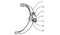
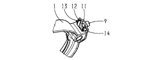
本発明に基づくアセンブリは、シフトシャフト4に固定したガイドプレート5を有する操作ユニット3を備えている。図示の実施形態ではガイドプレート5は2つのスロット6、7備えており、これらのスロット6、7は操作されるシフトフォーク1、2にそれぞれ割り当てられている。各スロット6、7に当該のシフトフォーク1、2の操作ピン9、10が通されている。シフトフォーク1はこの場合、双方向の運動に関してばねが介在するようにマウントされたシフトフォークとして形成され、シフトフォーク2にはこの場合ばねの介在はない。ガイドプレート5の旋回運動はスロット7に通された操作ピン10を介してシフトフォーク2に伝達される。そのために操作ピン10をシフトフォーク2に直接固定することができる。図2ないし図4で明かなように、操作ピン9はシフトフォーク1に旋回可能又は回転可能に取り付けられたレバープレート11に固定されている。レバープレート11はシフトレール8をほぼ横切って整列された支持ピン15によりシフトフォーク1に取り付けられている。こうしてガイドプレート5の旋回運動がスロット6に通された操作ピン9によりレバープレート11に伝達される。
The assembly according to the invention comprises an
撓みばね12はこの場合シフトフォーク1の双方向の運動に対して関与するように、或いはシフトフォークの双方向運動における動力伝達経路に介在するように設けられている。撓みばね12は、ばねクランプ、掛け金、レッグスプリング等の形態で形成することができる。撓みばね12の脚部はレバープレート11の、特に図4で明かな駆動ピン13、14に支えられる。こうしてレバープレート11の旋回運動は撓みばね12を介してシフトフォークに弾力的に伝達されるから、シフトフォーク1はシフトスリーブ等の操作のために軸方向に移動させられる。レバープレート11の旋回運動を図4に二重矢印で示唆した。
In this case, the
本発明に基づき提案されるアセンブリでシフトフォーク1の軸方向運動を行うために撓みばね12及びこれと結合された伝動機構を使用することによって、最小の軸方向取付けスペースでシフトフォークの双方向の運動に対してばねの介在が実現される。
By using the
1 シフトフォーク
2 シフトフォーク
3 操作ユニット
4 シフトシャフト
5 ガイドプレート
6 スロット
7 スロット
8 シフトレール
9 操作ピン
10 操作ピン
11 レバープレート
12 撓みばね
13 駆動ピン
14 駆動ピン
15 支持ピン
DESCRIPTION OF
Claims (6)
少なくとも1個の撓みばね(12)を用いたばねマウント構造が設けられていることを特徴とするアセンブリ。 The shift fork (1) mounted on the shift rail (8) has at least one operation unit (3) for operating at least an axially directed shift movement, and the shift fork (1) In an assembly for operation of at least one shift fork (1) of a vehicle transmission, provided with a spring mount structure with a spring interposed for bidirectional or unidirectional movement,
An assembly, characterized in that a spring mounting structure using at least one deflection spring (12) is provided.
Applications Claiming Priority (2)
| Application Number | Priority Date | Filing Date | Title |
|---|---|---|---|
| DE102008042960.0 | 2008-10-20 | ||
| DE102008042960.0A DE102008042960B4 (en) | 2008-10-20 | 2008-10-20 | Arrangement for actuating at least one shift fork in a transmission |
Publications (2)
| Publication Number | Publication Date |
|---|---|
| JP2010096352A true JP2010096352A (en) | 2010-04-30 |
| JP5592633B2 JP5592633B2 (en) | 2014-09-17 |
Family
ID=42034715
Family Applications (1)
| Application Number | Title | Priority Date | Filing Date |
|---|---|---|---|
| JP2009241288A Expired - Fee Related JP5592633B2 (en) | 2008-10-20 | 2009-10-20 | Assembly for operation of transmission shift forks |
Country Status (3)
| Country | Link |
|---|---|
| US (1) | US8015896B2 (en) |
| JP (1) | JP5592633B2 (en) |
| DE (1) | DE102008042960B4 (en) |
Families Citing this family (2)
| Publication number | Priority date | Publication date | Assignee | Title |
|---|---|---|---|---|
| KR101543169B1 (en) * | 2014-08-01 | 2015-08-13 | 현대자동차주식회사 | Structure of dual shift fork |
| FR3056667A1 (en) * | 2016-09-29 | 2018-03-30 | Peugeot Citroen Automobiles Sa | SYSTEM FOR THE INTERNAL CONTROL OF A GEARBOX OF A VEHICLE, IN PARTICULAR A MOTOR VEHICLE |
Citations (4)
| Publication number | Priority date | Publication date | Assignee | Title |
|---|---|---|---|---|
| JPH0532620B2 (en) * | 1983-10-25 | 1993-05-17 | Fuji Heavy Ind Ltd | |
| JP2522793B2 (en) * | 1987-05-08 | 1996-08-07 | 日産自動車株式会社 | Gear shifting operation mechanism of transmission |
| JP2000170887A (en) * | 1993-12-01 | 2000-06-23 | Deere & Co | Shift lever assembly of transmission |
| US6942435B2 (en) * | 2000-02-19 | 2005-09-13 | Robert Bosch Gmbh | Machine tool |
Family Cites Families (17)
| Publication number | Priority date | Publication date | Assignee | Title |
|---|---|---|---|---|
| DE1005385B (en) * | 1953-10-03 | 1957-03-28 | Opel Adam Ag | Switching device of transfer cases for vehicles with four-wheel drive |
| DE1155354B (en) * | 1961-08-08 | 1963-10-03 | Fichtel & Sachs Ag | Foot switch for motorcycles and mopeds |
| US4098380A (en) * | 1977-04-07 | 1978-07-04 | Thomas Dalton A | Gear selector mechanism |
| US4228693A (en) * | 1978-12-11 | 1980-10-21 | Borg-Warner Corporation | Transmission shift control apparatus |
| US4498350A (en) | 1982-09-20 | 1985-02-12 | Eaton Corporation | Shifting mechanism |
| US4529080A (en) | 1983-08-19 | 1985-07-16 | Chrysler Corporation | Bi-directional spring loaded shift fork assembly |
| US4770280A (en) * | 1987-06-05 | 1988-09-13 | Chrysler Motors Corporation | Snap-action arrangement for transfer case synchronizer |
| GB2236152B (en) | 1989-09-23 | 1993-11-24 | Massey Ferguson Mfg | Gear change mechanism |
| US5159847A (en) * | 1991-09-12 | 1992-11-03 | New Venture Gear, Inc. | Sector plate for transfer case |
| US5517876A (en) * | 1994-08-04 | 1996-05-21 | Eaton Corporation | Transmission spring loaded shift device |
| US6082514A (en) * | 1999-01-05 | 2000-07-04 | Warn Industries, Inc. | Actuator for clutch ring |
| US6619153B2 (en) | 2001-03-30 | 2003-09-16 | New Venture Gear, Inc. | Spring-loaded fork assembly for shift system |
| US6619159B2 (en) * | 2001-05-07 | 2003-09-16 | Donald E. Galat | Nutrunner safety sleeve |
| DE10128318A1 (en) * | 2001-06-01 | 2002-12-19 | Gif Gmbh | Gear change mechanism for use in road vehicle includes framework and pattern plate with rotating and reciprocating shaft and forks engaging gear assemblies |
| DE10316163A1 (en) * | 2003-04-09 | 2004-11-11 | Dr.Ing.H.C. F. Porsche Ag | Multi-stage manual transmission for an internal combustion engine |
| US20050223833A1 (en) * | 2004-03-31 | 2005-10-13 | Herzog Contracting Corp. | Transmission with top mounted shift mechanism |
| US20060090584A1 (en) * | 2004-11-04 | 2006-05-04 | Kwang Yang Motor Co., Ltd. | Gear shift assembly for all-terrain vehicles |
-
2008
- 2008-10-20 DE DE102008042960.0A patent/DE102008042960B4/en not_active Expired - Fee Related
-
2009
- 2009-09-24 US US12/566,027 patent/US8015896B2/en not_active Expired - Fee Related
- 2009-10-20 JP JP2009241288A patent/JP5592633B2/en not_active Expired - Fee Related
Patent Citations (4)
| Publication number | Priority date | Publication date | Assignee | Title |
|---|---|---|---|---|
| JPH0532620B2 (en) * | 1983-10-25 | 1993-05-17 | Fuji Heavy Ind Ltd | |
| JP2522793B2 (en) * | 1987-05-08 | 1996-08-07 | 日産自動車株式会社 | Gear shifting operation mechanism of transmission |
| JP2000170887A (en) * | 1993-12-01 | 2000-06-23 | Deere & Co | Shift lever assembly of transmission |
| US6942435B2 (en) * | 2000-02-19 | 2005-09-13 | Robert Bosch Gmbh | Machine tool |
Also Published As
| Publication number | Publication date |
|---|---|
| JP5592633B2 (en) | 2014-09-17 |
| DE102008042960B4 (en) | 2018-06-07 |
| DE102008042960A1 (en) | 2010-04-22 |
| US20100095797A1 (en) | 2010-04-22 |
| US8015896B2 (en) | 2011-09-13 |
Similar Documents
| Publication | Publication Date | Title |
|---|---|---|
| JP5887199B2 (en) | Parking lock device for automatic transmission | |
| KR20150048770A (en) | Force accumulator for an on-load tap changer | |
| JP4784363B2 (en) | Parking lock device for transmission | |
| JP5592633B2 (en) | Assembly for operation of transmission shift forks | |
| JP2006220303A (en) | Two way friction clutch or braking device for transmission | |
| CN211969570U (en) | Vehicle steering system and vehicle | |
| JP2010266044A (en) | Operation device for transmission | |
| KR101656959B1 (en) | Shift control apparatus for manual transmission | |
| JP2009079653A (en) | Electric actuator | |
| JP5145518B2 (en) | Rocker lever actuator specifically for operating vehicle clutches | |
| JP5109943B2 (en) | Clutch device and seat device | |
| JP2012096719A (en) | Driving force distributing apparatus | |
| JP4973604B2 (en) | Parking device structure | |
| JP2009208756A (en) | Lock mechanism for vehicle | |
| JP5934841B2 (en) | Multi-disc transmission | |
| JP2009243516A (en) | Range switching device | |
| RU2526866C2 (en) | Mechanical latch for main drive assembly | |
| JP2022505716A (en) | Operating mechanisms, clutch actuators and transmission actuators with improved vibration characteristics | |
| WO2014208214A1 (en) | Shifting mechanism for multidisc transmission | |
| JP2016102552A (en) | Engagement/disengagement mechanism of dual clutch | |
| JP2013185608A (en) | Shift device of transmission for vehicle | |
| WO2011007791A1 (en) | Clutch device | |
| JP2008128465A (en) | Operating device of transmission | |
| JP2010266025A (en) | Shift mechanism | |
| WO2020211039A1 (en) | Parking mechanism for realizing parking function by shift fork shaft driving, and dual-clutch transmission |
Legal Events
| Date | Code | Title | Description |
|---|---|---|---|
| RD03 | Notification of appointment of power of attorney |
Free format text: JAPANESE INTERMEDIATE CODE: A7423 Effective date: 20111111 |
|
| RD04 | Notification of resignation of power of attorney |
Free format text: JAPANESE INTERMEDIATE CODE: A7424 Effective date: 20120411 |
|
| A621 | Written request for application examination |
Free format text: JAPANESE INTERMEDIATE CODE: A621 Effective date: 20120925 |
|
| A521 | Request for written amendment filed |
Free format text: JAPANESE INTERMEDIATE CODE: A523 Effective date: 20140219 |
|
| TRDD | Decision of grant or rejection written | ||
| A01 | Written decision to grant a patent or to grant a registration (utility model) |
Free format text: JAPANESE INTERMEDIATE CODE: A01 Effective date: 20140729 |
|
| A61 | First payment of annual fees (during grant procedure) |
Free format text: JAPANESE INTERMEDIATE CODE: A61 Effective date: 20140801 |
|
| R150 | Certificate of patent or registration of utility model |
Ref document number: 5592633 Country of ref document: JP Free format text: JAPANESE INTERMEDIATE CODE: R150 |
|
| R250 | Receipt of annual fees |
Free format text: JAPANESE INTERMEDIATE CODE: R250 |
|
| R250 | Receipt of annual fees |
Free format text: JAPANESE INTERMEDIATE CODE: R250 |
|
| R250 | Receipt of annual fees |
Free format text: JAPANESE INTERMEDIATE CODE: R250 |
|
| R250 | Receipt of annual fees |
Free format text: JAPANESE INTERMEDIATE CODE: R250 |
|
| LAPS | Cancellation because of no payment of annual fees |