JP2010096259A - Roller type one-way clutch - Google Patents
Roller type one-way clutch Download PDFInfo
- Publication number
- JP2010096259A JP2010096259A JP2008267227A JP2008267227A JP2010096259A JP 2010096259 A JP2010096259 A JP 2010096259A JP 2008267227 A JP2008267227 A JP 2008267227A JP 2008267227 A JP2008267227 A JP 2008267227A JP 2010096259 A JP2010096259 A JP 2010096259A
- Authority
- JP
- Japan
- Prior art keywords
- outer ring
- roller
- way clutch
- end surface
- Prior art date
- Legal status (The legal status is an assumption and is not a legal conclusion. Google has not performed a legal analysis and makes no representation as to the accuracy of the status listed.)
- Granted
Links
Images


Classifications
-
- F—MECHANICAL ENGINEERING; LIGHTING; HEATING; WEAPONS; BLASTING
- F16—ENGINEERING ELEMENTS AND UNITS; GENERAL MEASURES FOR PRODUCING AND MAINTAINING EFFECTIVE FUNCTIONING OF MACHINES OR INSTALLATIONS; THERMAL INSULATION IN GENERAL
- F16D—COUPLINGS FOR TRANSMITTING ROTATION; CLUTCHES; BRAKES
- F16D41/00—Freewheels or freewheel clutches
- F16D41/06—Freewheels or freewheel clutches with intermediate wedging coupling members between an inner and an outer surface
- F16D41/064—Freewheels or freewheel clutches with intermediate wedging coupling members between an inner and an outer surface the intermediate members wedging by rolling and having a circular cross-section, e.g. balls
- F16D41/066—Freewheels or freewheel clutches with intermediate wedging coupling members between an inner and an outer surface the intermediate members wedging by rolling and having a circular cross-section, e.g. balls all members having the same size and only one of the two surfaces being cylindrical
- F16D41/067—Freewheels or freewheel clutches with intermediate wedging coupling members between an inner and an outer surface the intermediate members wedging by rolling and having a circular cross-section, e.g. balls all members having the same size and only one of the two surfaces being cylindrical and the members being distributed by a separate cage encircling the axis of rotation
Landscapes
- Engineering & Computer Science (AREA)
- General Engineering & Computer Science (AREA)
- Mechanical Engineering (AREA)
- Pulleys (AREA)
- Rolling Contact Bearings (AREA)
Abstract
Description
本発明は、例えば自動車や産業機械などの駆動装置内でトルク伝達、バックストップ等の部品として使用されるローラ型ワンウェイクラッチに関するものである。 The present invention relates to a roller type one-way clutch used as a component for torque transmission, backstop, etc. in a drive device such as an automobile or an industrial machine.
一般に、ローラ型ワンウェイクラッチは、内周にカム面を有する少なくとも一つのポケットが形成された外輪と、外輪と同心に配置されており外周軌道面を有する内輪と、ポケット内に配置されて内輪の外周軌道面と外輪の内周カム面との間でトルクを伝達するローラと、ローラの空転側に接するスプリングなどから成っている。 In general, a roller type one-way clutch is composed of an outer ring having at least one pocket having a cam surface on the inner periphery, an inner ring arranged concentrically with the outer ring and having an outer raceway surface, and an inner ring arranged in the pocket. It consists of a roller that transmits torque between the outer raceway surface and the inner circumferential cam surface of the outer ring, a spring that contacts the idling side of the roller, and the like.
このような構成において、ローラ型ワンウェイクラッチはローラとカム面とで構成されるカム機構により、外輪に対して内輪を一方向のみに回転するようにしている。すなわち内輪は外輪に対して一方向で空転し、その逆方向でのみカム機構を介して外輪に回転トルクを与える構成になっている。 In such a configuration, the roller-type one-way clutch rotates the inner ring in only one direction with respect to the outer ring by a cam mechanism including a roller and a cam surface. That is, the inner ring is configured to idle in one direction with respect to the outer ring, and to apply rotational torque to the outer ring via the cam mechanism only in the opposite direction.
ローラ型ワンウェイクラッチでは、確実な噛み合わせを得るため、トルク伝達部材であるローラや、それを付勢するスプリングなどがポケットから軸方向及び径方向に脱落しないようにする必要がある。 In the roller type one-way clutch, in order to obtain a reliable engagement, it is necessary to prevent a roller serving as a torque transmission member, a spring for urging the roller, and the like from dropping from the pocket in the axial direction and the radial direction.
従来の、例えば二輪車用のスタータに使用されているワンウェイクラッチでは、例えば特許文献1に開示のように、ローラ及びスプリングが脱落するのを防止するために、外輪の両側に側板を設けることが提案されている。
In a conventional one-way clutch used for a starter for a motorcycle, for example, as disclosed in
この出願の発明に関連する先行技術文献情報としては次のものがある。
特許文献1に開示されているように、ローラやスプリングの脱落防止のために外輪の軸方向の両側に側板を設けることが必要であった。また、ワンウェイクラッチが内輪に装着される前の状態では、ローラやスプリングの径方向への脱落防止手段を別に設けることが必要であった。いずれの場合でも、コスト低減の支障となっていた。
As disclosed in
従って、ワンウェイクラッチの噛み合い及び空転において従来同様の信頼性を確保でき、従来に比べてコストが低減した、ローラ及びスプリングの脱落防止手段が設けられたローラ型ワンウェイクラッチが望まれている。 Accordingly, there is a demand for a roller type one-way clutch provided with means for preventing the rollers and springs from dropping, which can ensure the same reliability as in the prior art in meshing and idling of the one-way clutch, and has a reduced cost compared to the conventional one.
そこで本発明は、ローラ型ワンウェイクラッチにおいて、外輪の軸方向端面に、ポケットの少なくとも一部を覆うカバー部を設けることにより、ローラ及びスプリングが脱落することを防止し、噛み合い及び空転において、信頼性が向上したローラ型ワンウェイクラッチを提供することを目的としている。 Therefore, in the roller type one-way clutch, by providing a cover portion that covers at least a part of the pocket on the axial end surface of the outer ring, the roller and the spring are prevented from falling off, and the engagement and idling are reliable. An object of the present invention is to provide a roller type one-way clutch with improved performance.
上記目的を達成するため、本発明のローラ型ワンウェイクラッチは、
カム面を有する凹部として形成された少なくとも一つのポケットを内周に備え、軸方向一端面の内径側に段部が設けられている環状の外輪と、
外輪に対して半径方向内径側に離間され、相対回転自在に同心状に配置され、環状の外周軌道面を有する内輪と、
ポケット内に配置されて内輪の外周軌道面と外輪の内周カム面との間でトルクを伝達するローラと、
円筒部と、外輪の段部に嵌合し円筒部から外径方向へ延在するフランジ部を備え、ローラ径よりも小さい円周方向の窓幅を有すると共に、径方向には貫通しているが、軸方向では両端部とも閉じられている、すなわちローラが着座するように四辺の囲まれたほぼ矩形の窓が円筒部に設けられている、外輪に対して相対回動自在である保持器と、
ポケットに配置され、ローラをカム面との係合方向に付勢するスプリングとから成り、
外輪の軸方向端面に、ポケットの少なくとも一部を覆うカバー部が設けられていることを特徴としている。
In order to achieve the above object, the roller type one-way clutch of the present invention comprises:
An annular outer ring provided with at least one pocket formed as a recess having a cam surface on the inner periphery, and a stepped portion provided on the inner diameter side of one axial end surface;
An inner ring that is spaced radially outward from the outer ring and is concentrically disposed so as to be relatively rotatable, and has an annular outer raceway surface;
A roller disposed in the pocket for transmitting torque between the outer raceway surface of the inner ring and the inner cam surface of the outer ring;
A cylindrical portion and a flange portion that fits into a step portion of the outer ring and extends from the cylindrical portion in the outer diameter direction, has a circumferential window width smaller than the roller diameter, and penetrates in the radial direction. However, in the axial direction, both ends are closed, that is, a substantially rectangular window surrounded by four sides is provided in the cylindrical portion so that the roller is seated, and the cage is rotatable relative to the outer ring. When,
Consisting of a spring arranged in the pocket and biasing the roller in the direction of engagement with the cam surface,
The axial direction end surface of the outer ring is provided with a cover portion that covers at least a part of the pocket.
また、本発明のローラ型ワンウェイクラッチは、外輪の段部が設けられている軸方向一端面の反対側の端面にカバー部が設けられていることを特徴としている。 The roller type one-way clutch of the present invention is characterized in that a cover portion is provided on an end surface opposite to one end surface in the axial direction where the step portion of the outer ring is provided.
また、本発明のローラ型ワンウェイクラッチは、カバー部がポケット部の円周方向でスプリング装着側に設けられていることを特徴としている。 The roller type one-way clutch of the present invention is characterized in that the cover portion is provided on the spring mounting side in the circumferential direction of the pocket portion.
また、本発明のローラ型ワンウェイクラッチは、カバー部がミーリング加工により形成されることを特徴としている。 In the roller type one-way clutch of the present invention, the cover portion is formed by milling.
また、本発明のローラ型ワンウェイクラッチは、カバー部が外輪と一体で設けられていることを特徴としている。 The roller type one-way clutch of the present invention is characterized in that the cover part is provided integrally with the outer ring.
本発明のローラ型ワンウェイクラッチでは、外輪のローラ及びスプリングが配置されるポケットを覆うカバー部を外輪の軸方向端面に設けることにより、ワンウェイクラッチが出入力部材に装着されていない状態であっても、外輪の両側に側板を設けずにローラ及び/またはスプリングの軸方向への脱落を防止できる。またポケットの一部分をカバー部で覆うことにより、開放部よりポケット内のゴミなどの異物を排出することができる。 In the roller type one-way clutch of the present invention, even if the one-way clutch is not attached to the input / output member by providing a cover portion covering the pocket in which the rollers and springs of the outer ring are disposed on the axial end surface of the outer ring. The roller and / or spring can be prevented from falling off in the axial direction without providing side plates on both sides of the outer ring. Further, by covering a part of the pocket with the cover portion, foreign matter such as dust in the pocket can be discharged from the open portion.
従って、従来のローラ型ワンウェイクラッチに必要であった側板が廃止でき、部品数の削減によりコストが低減したローラ型ワンウェイクラッチが提供可能である。 Therefore, the side plate required for the conventional roller type one-way clutch can be eliminated, and a roller type one-way clutch with reduced cost can be provided by reducing the number of parts.
加えて、外輪と、ポケットの軸方向片側端部フランジと、円周方向ではローラ径より小さい円周方向の窓幅を持ち、径方向には貫通しているが、軸方向では両端部とも閉じられている、すなわちローラが着座するように四辺の囲まれたほぼ矩形の窓を持った保持器とによりローラの軸方向及び内径方向への保持器からの脱落を防止している。 In addition, it has an outer ring, a flange on one end in the axial direction of the pocket, and a circumferential window width smaller than the roller diameter in the circumferential direction and penetrates in the radial direction, but both ends are closed in the axial direction. In other words, the retainer having a substantially rectangular window surrounded by four sides so that the roller is seated prevents the roller from dropping from the retainer in the axial direction and the inner diameter direction.
また、保持器のフランジを外輪端面内径部に設けられた段部に嵌合し、このフランジ側外輪端面にジェネレータなどを固定することにより、保持器の脱落を防止している。 Further, the cage is prevented from falling off by fitting the flange of the cage to a step portion provided on the inner diameter portion of the outer ring end surface and fixing a generator or the like to the flange side outer ring end surface.
また、保持器が外輪に対して相対回転自在であることにより、径方向のローラの脱落を防止するために、保持器の円周方向の窓幅をローラ径より小さくしても、ワンウェイクラッチ作動の際の、噛み合い時のローラの移動、また空転時のローラの移動において保持器がローラの動きを妨害しないため、スムースな噛み合い及び空転が可能となり、また全てのローラの動きに対し、保持器が同期作用を及ぼし、より噛み合い信頼性が向上したローラ型ワンウェイクラッチが可能となる。 In addition, since the cage is rotatable relative to the outer ring, the one-way clutch is operated even if the circumferential window width of the cage is smaller than the roller diameter in order to prevent the roller in the radial direction from falling off. In this case, the cage does not interfere with the movement of the roller during meshing and the roller during idling, so that the meshing and idling of the roller can be performed smoothly. Exerts a synchronizing action, and a roller type one-way clutch with improved meshing reliability is possible.
以下、添付図面を参照して本発明の実施例を詳細に説明する。なお、各図面を通して同一符号は同一又は対応部分を示すものである。また、以下に説明する実施例は例示として本発明を示しているに過ぎず、その他の変更が可能なことは言うまでもない。 Hereinafter, embodiments of the present invention will be described in detail with reference to the accompanying drawings. Note that the same reference numerals denote the same or corresponding parts throughout the drawings. Further, the embodiments described below are merely examples of the present invention, and it goes without saying that other modifications are possible.
図1は、本発明の一実施例のローラ型ワンウェイクラッチを示すカバー部が設けられている側からの正面図であり、図3は図1の裏側より見た正面図である。また、図2は、図3のA−O−A線に沿った断面図である。 FIG. 1 is a front view showing a roller type one-way clutch according to an embodiment of the present invention from a side where a cover portion is provided, and FIG. 3 is a front view seen from the back side of FIG. 2 is a cross-sectional view taken along the line A-O-A in FIG.
図1乃至図3は、ローラがカム面に噛み合っている状態、すなわちワンウェイクラッチが高負荷の下で噛み合い、ロックしている状態を示している。 1 to 3 show a state where the roller is engaged with the cam surface, that is, a state where the one-way clutch is engaged and locked under a high load.
図1に示すように、ローラ型ワンウェイクラッチ30は、カム面12を有する凹部として形成された複数のポケット4を内周に備えた環状の外輪1と、外輪1に対して半径方向内径側に離間され、相対回転自在に同心状に配置され、環状の外周軌道面11を有する内輪2(図2において図示)と、ポケット4内に配置されて内輪2の外周軌道面11と外輪1の内周カム面12との間でトルクを伝達するローラ3と、ポケット4内に配置され、ローラ3をカム面12との係合方向に付勢するスプリング5と、ローラ3を保持する保持器6とから成っている。保持器6は、外輪1及び内輪2のいずれにも固定されておらず、外輪1及び内輪2に対して相対回動自在となっている。
As shown in FIG. 1, the roller type one-
本実施例においては、外輪1に設けられるポケット4は、円周方向等配に3箇所設けられている。また、外輪1を不図示の出入力部材などに固定するために用いられ、軸方向に貫通するボルト孔8も円周方向等分に3箇所設けられており、ポケット4とボルト孔8とは等間隔で交互に配置されている。もちろん、ポケット4の数は、トルクの大きさに応じて、例えば3乃至6個などの複数個の設定が可能であることは言うまでもない。
In this embodiment, the pockets 4 provided in the
図2及び図3に示すように、ローラ3を保持する保持器6は、円筒部10と、円筒部10の軸方向一端部から外径方向へ延在する環状のフランジ部17を備えている。尚、図3では、フランジ部17は、ポケット4が見えるように一部破断して示している。
As shown in FIGS. 2 and 3, the
また、保持器6は、ローラ3の数に対応して、窓18を有する。窓18は、径方向には貫通しているが、軸方向では、フランジ部17側も、フランジ部17と対向する端部19側でも閉じられている。円周方向では、ローラ径よりも小さな窓幅となっている。すなわち、ローラ3は、四辺の囲まれたほぼ矩形の窓18内に着座しており、ローラ3の内径方向への脱落を防止できると同時にローラ3の軸方向への脱落を防止できる。窓18とローラ3との関係を示すため、図1においては、図中一番上の窓18は、端部19を破断して示している。
The
図2及び図3に示すように、外輪1の軸方向端面21に環状の段部13が設けられ、段部13に保持器6のフランジ部17が係合している。段部13の軸方向深さは、フランジ部17の厚さよりわずかに大きくしてあり、フランジ部17が段部13に係合すると、外輪1の軸方向端面とフランジ部17の軸方向端面との間にはクリアランスが生じる。
As shown in FIGS. 2 and 3, an
このため、保持器6が外輪1に対して相対回動自在となり、保持器6の軸方向への抜け止めが可能となる。
For this reason, the
図1に示すように、外輪1の軸方向端面22に、ポケット4の数に対応して、ポケット4の少なくとも一部を覆うカバー部25が外輪1と一体に設けられている。カバー部25は、ポケット4の円周方向でスプリング5の装着側に設けられている。
As shown in FIG. 1, a
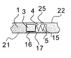
図4は、本発明の一実施例のローラ型ワンウェイクラッチを拡大した図3のB−B線に沿った断面図であり、カバー部25の詳細を示している。
4 is an enlarged cross-sectional view taken along the line BB of FIG. 3 showing the roller type one-way clutch according to the embodiment of the present invention, and shows details of the
図4に示すように、カバー部25は外輪1のポケット4内のスプリング5の端部15を覆うようにポケット4の一部分に設けられており、外輪1の軸方向端面22側へのスプリング5の脱落を防止している。
As shown in FIG. 4, the
スプリング5のタブ16は、ローラ3の軸方向の端面と保持器6のフランジ部17との間に挟持されている。このように構成したため、外輪1の軸方向端面21側へのスプリング5の脱落を防止できる。
The
本実施例では、スプリング5はアコーデオンスプリングであるが、コイルスプリングなど、その他の形状のスプリングを用いることも可能である。
In this embodiment, the
カバー部25は、保持器6のフランジ部17が設けられている外輪1の軸方向端面21側とは反対側の軸方向端面22側に設ける。これは、スプリング5のタブ16、ローラ3が着座している保持器6の窓18、フランジ部17及びカバー部25によって、スプリング5の軸方向への脱落を防止できるからである。
The
カバー部25は、ミーリング加工などにより形成する。ポケット4のカバー部25を設ける位置においてカバー部25の厚さ分を残し、ミーリング加工により、外輪1のポケット4を切削加工することによりカバー部25を形成することができる。
The
また、上記実施例ではカバー部25は外輪1と一体に形成したが、外輪1とは別体で形成し、外輪1に固定することも可能である。
In the above embodiment, the
1 外輪
2 内輪
3 ローラ
4 ポケット
5 スプリング
6 保持器
8 ボルト孔
10 保持器の円筒部
11 内輪の外周軌道面
12 カム面
13 段部
15 スプリングの一端
16 スプリングのタブ
17 保持器のフランジ部
18 保持器の窓
19 保持器の端部
21 外輪の端面
22 外輪の端面
25 カバー部
30 ローラ型ワンウェイクラッチ
DESCRIPTION OF
Claims (5)
前記外輪に対して半径方向内径側に離間され、相対回転自在に同心状に配置された内輪と、
前記ポケットに配置され、前記カム面に係合し、前記外輪と前記内輪との間でトルクを伝達するローラと、
円筒部と、前記円筒部から外径方向へ延在し、前記外輪の前記段部に嵌合するフランジ部を備え、前記ローラの径よりも小さい円周方向の窓幅を有し、前記ローラを保持する窓が前記円筒部に設けられている、前記外輪に対して相対回動自在である保持器と、
前記ポケットに配置され、前記ローラを前記カム面との係合方向に付勢するスプリングとを備えるワンウェイクラッチにおいて、
前記外輪の軸方向端面に、前記ポケットの少なくとも一部を覆うカバー部が設けられていることを特徴とするワンウェイクラッチ。 An outer ring in which at least one pocket having a cam surface is formed on the inner periphery, and a step portion is provided on the inner diameter side of the one axial end surface;
An inner ring that is spaced apart radially inward from the outer ring and is concentrically disposed so as to be relatively rotatable;
A roller disposed in the pocket, engaging the cam surface, and transmitting torque between the outer ring and the inner ring;
A cylindrical portion, a flange portion extending from the cylindrical portion in the outer diameter direction, and fitted to the step portion of the outer ring, having a circumferential window width smaller than the diameter of the roller, and the roller A cage that is provided in the cylindrical portion and is rotatable relative to the outer ring;
In the one-way clutch provided with a spring disposed in the pocket and biasing the roller in the direction of engagement with the cam surface,
The one-way clutch, wherein a cover portion that covers at least a part of the pocket is provided on an end surface in the axial direction of the outer ring.
Priority Applications (2)
| Application Number | Priority Date | Filing Date | Title |
|---|---|---|---|
| JP2008267227A JP5205207B2 (en) | 2008-10-16 | 2008-10-16 | Roller type one-way clutch |
| US12/580,096 US8393453B2 (en) | 2008-10-16 | 2009-10-15 | One-way clutch of roller type |
Applications Claiming Priority (1)
| Application Number | Priority Date | Filing Date | Title |
|---|---|---|---|
| JP2008267227A JP5205207B2 (en) | 2008-10-16 | 2008-10-16 | Roller type one-way clutch |
Publications (2)
| Publication Number | Publication Date |
|---|---|
| JP2010096259A true JP2010096259A (en) | 2010-04-30 |
| JP5205207B2 JP5205207B2 (en) | 2013-06-05 |
Family
ID=42107768
Family Applications (1)
| Application Number | Title | Priority Date | Filing Date |
|---|---|---|---|
| JP2008267227A Active JP5205207B2 (en) | 2008-10-16 | 2008-10-16 | Roller type one-way clutch |
Country Status (2)
| Country | Link |
|---|---|
| US (1) | US8393453B2 (en) |
| JP (1) | JP5205207B2 (en) |
Families Citing this family (9)
| Publication number | Priority date | Publication date | Assignee | Title |
|---|---|---|---|---|
| JP5274050B2 (en) * | 2008-02-27 | 2013-08-28 | Nskワーナー株式会社 | Roller type one-way clutch |
| JP5175139B2 (en) * | 2008-06-06 | 2013-04-03 | Nskワーナー株式会社 | Roller type one-way clutch for motorcycle starters |
| JP5133191B2 (en) * | 2008-10-03 | 2013-01-30 | Nskワーナー株式会社 | Roller type one-way clutch |
| JP5133201B2 (en) * | 2008-10-28 | 2013-01-30 | Nskワーナー株式会社 | Roller type one-way clutch |
| JP2010106956A (en) * | 2008-10-30 | 2010-05-13 | Nsk Warner Kk | One-way clutch of roller type |
| JP2011085245A (en) * | 2009-10-19 | 2011-04-28 | Nsk Warner Kk | One-way clutch |
| JP6246732B2 (en) * | 2012-11-26 | 2017-12-13 | Nskワーナー株式会社 | Roller type one-way clutch |
| JP6070300B2 (en) * | 2013-03-12 | 2017-02-01 | 株式会社ジェイテクト | Power generation device and one-way clutch structure |
| DE102014226889A1 (en) | 2014-01-10 | 2015-07-16 | Borgwarner Inc. | Anti-kick clutch for a starter gear |
Citations (6)
| Publication number | Priority date | Publication date | Assignee | Title |
|---|---|---|---|---|
| JP2005172181A (en) * | 2003-12-15 | 2005-06-30 | Koyo Seiko Co Ltd | Pulley unit with one-way clutch |
| JP2007064475A (en) * | 2005-08-05 | 2007-03-15 | Exedy Corp | One-way clutch |
| JP2007278426A (en) * | 2006-04-10 | 2007-10-25 | Nsk Warner Kk | Roller type one-way clutch |
| WO2008047457A1 (en) * | 2006-10-16 | 2008-04-24 | Nsk-Warner K.K. | Roller-type one-way clutch |
| JP2008138723A (en) * | 2006-11-30 | 2008-06-19 | Ntn Corp | One-way clutch |
| JP2008138712A (en) * | 2006-11-30 | 2008-06-19 | Ntn Corp | One-way clutch |
Family Cites Families (53)
| Publication number | Priority date | Publication date | Assignee | Title |
|---|---|---|---|---|
| US1708215A (en) | 1925-08-27 | 1929-04-09 | Delco Remy Corp | Clutch |
| US2902125A (en) | 1955-08-11 | 1959-09-01 | Gen Motors Corp | Engine starting apparatus |
| US2843238A (en) | 1955-11-23 | 1958-07-15 | Parkersburg Aetna Corp | One-way clutch |
| US3011606A (en) | 1957-07-26 | 1961-12-05 | Borg Warner | Roller clutch |
| US3166169A (en) | 1961-12-22 | 1965-01-19 | Borg Warner | One-way roller clutch with plural cage means |
| US3190417A (en) | 1963-04-05 | 1965-06-22 | Walter H Bacon | Over-running clutch |
| US3547238A (en) | 1969-01-24 | 1970-12-15 | Gen Motors Corp | Freewheel device |
| US3656591A (en) | 1970-09-04 | 1972-04-18 | Marland One Way Clutch Co Inc | One-way self-alining torque unit |
| US3718212A (en) | 1971-12-01 | 1973-02-27 | Borg Warner | Phased roller clutch |
| DE2928587C2 (en) | 1979-07-14 | 1984-11-29 | Volkswagenwerk Ag, 3180 Wolfsburg | Pinch roller overrunning clutch |
| EP0237243A1 (en) | 1986-03-13 | 1987-09-16 | Borg-Warner Automotive, Inc. | One-way roller clutch accordion spring with stabilizer |
| US4724940A (en) | 1986-04-07 | 1988-02-16 | General Motors Corporation | Overrunning clutch with improved roller retention |
| DE3620804A1 (en) | 1986-06-20 | 1987-12-23 | Schaeffler Waelzlager Kg | KAEFIG FOR A FREEWHEEL |
| JPH0735823B2 (en) | 1987-03-25 | 1995-04-19 | エヌエスケー・ワーナー株式会社 | Roller synchronous one-way clutch |
| US5271486A (en) * | 1989-03-13 | 1993-12-21 | Ntn Corporation | Torque limiter |
| JPH02309021A (en) * | 1989-05-19 | 1990-12-25 | Ntn Corp | Consolidated assembly of one-way clutch/bearing |
| US4932508A (en) | 1989-08-07 | 1990-06-12 | General Motors Corporation | Overrunning roller clutch with protected springs |
| JP2970096B2 (en) | 1991-08-13 | 1999-11-02 | スズキ株式会社 | Engine starter clutch mechanism lubrication device |
| CA2072444A1 (en) | 1991-08-27 | 1993-02-28 | James W. Warnke | Cross groove constant velocity joint having fixed center |
| DE4219154C2 (en) * | 1992-06-11 | 1995-04-20 | Ford Werke Ag | Roller or sprag freewheel with additional roller bearings on the side |
| US5279400A (en) | 1992-12-08 | 1994-01-18 | Borg-Warner Automotive Inc. | One-way roller clutch |
| US5328010A (en) | 1993-10-13 | 1994-07-12 | General Motors Corporation | Overrunning roller clutch with improved self protecting spring |
| DE9318556U1 (en) | 1993-12-06 | 1994-02-10 | Schaeffler Waelzlager Kg | Freewheel cage with reinforcement ring |
| JP3156516B2 (en) | 1994-08-24 | 2001-04-16 | スズキ株式会社 | Starting device for motorcycle engine |
| JP4064488B2 (en) | 1996-04-25 | 2008-03-19 | 株式会社ユニバンス | One-way clutch |
| US5842548A (en) | 1996-04-25 | 1998-12-01 | Fuji Univance Corporation | One-way clutch |
| JPH10227318A (en) | 1996-12-12 | 1998-08-25 | Mitsuba Corp | One-way clutch |
| JP3780371B2 (en) | 1996-12-25 | 2006-05-31 | 株式会社ジェイテクト | One-way clutch |
| KR200153576Y1 (en) | 1997-07-09 | 1999-08-02 | 정대인 | The antibacklash device in the fishing reel |
| JP4115606B2 (en) | 1998-11-06 | 2008-07-09 | Nskワーナー株式会社 | Roller clutch mechanism |
| JP2003148518A (en) | 2001-11-07 | 2003-05-21 | Musashi Seimitsu Ind Co Ltd | One-way clutch |
| JP2003172377A (en) | 2001-12-07 | 2003-06-20 | Honda Motor Co Ltd | Manufacturing method for one-way clutch |
| JP4188143B2 (en) | 2002-06-03 | 2008-11-26 | 株式会社ユタカ技研 | One-way clutch |
| JP2004308888A (en) | 2003-02-18 | 2004-11-04 | Nsk Warner Kk | One-way clutch device and manufacturing method |
| US6848552B2 (en) | 2003-04-16 | 2005-02-01 | Ntn Corporation | Starter pulley with integral clutch |
| JP2004346951A (en) | 2003-05-20 | 2004-12-09 | Toyoda Mach Works Ltd | One-way clutch |
| JP4260581B2 (en) | 2003-09-03 | 2009-04-30 | 本田技研工業株式会社 | One-way clutch |
| JP2006275219A (en) | 2005-03-30 | 2006-10-12 | Origin Electric Co Ltd | One-way roller clutch |
| DE112006000987T5 (en) | 2005-04-20 | 2008-03-06 | Ntn Corp. | Lubricating grease composition, bearing with enclosed grease and rotation transfer device with built-in one-way clutch |
| JP4749917B2 (en) * | 2006-04-10 | 2011-08-17 | Nskワーナー株式会社 | Roller type one-way clutch |
| TW200801364A (en) | 2006-06-22 | 2008-01-01 | Sanyang Industry Co Ltd | Unidirectional clutch |
| WO2008114468A1 (en) | 2007-03-20 | 2008-09-25 | Nsk-Warner K.K. | Roller-type one-way clutch |
| JP5274050B2 (en) | 2008-02-27 | 2013-08-28 | Nskワーナー株式会社 | Roller type one-way clutch |
| JP5160269B2 (en) | 2008-03-06 | 2013-03-13 | Nskワーナー株式会社 | Roller type one-way clutch |
| JP5037399B2 (en) | 2008-03-25 | 2012-09-26 | Nskワーナー株式会社 | Roller type one-way clutch |
| JP5118550B2 (en) | 2008-05-09 | 2013-01-16 | Nskワーナー株式会社 | Roller type one-way clutch for motorcycle starters |
| JP5175139B2 (en) | 2008-06-06 | 2013-04-03 | Nskワーナー株式会社 | Roller type one-way clutch for motorcycle starters |
| USD586832S1 (en) | 2008-06-13 | 2009-02-17 | Nsk-Warner K.K. | One-way clutch |
| JP5133191B2 (en) | 2008-10-03 | 2013-01-30 | Nskワーナー株式会社 | Roller type one-way clutch |
| JP5205211B2 (en) | 2008-10-20 | 2013-06-05 | Nskワーナー株式会社 | Roller type one-way clutch |
| JP5133201B2 (en) | 2008-10-28 | 2013-01-30 | Nskワーナー株式会社 | Roller type one-way clutch |
| JP2010106956A (en) | 2008-10-30 | 2010-05-13 | Nsk Warner Kk | One-way clutch of roller type |
| JP5133213B2 (en) | 2008-11-13 | 2013-01-30 | Nskワーナー株式会社 | Roller type one-way clutch |
-
2008
- 2008-10-16 JP JP2008267227A patent/JP5205207B2/en active Active
-
2009
- 2009-10-15 US US12/580,096 patent/US8393453B2/en active Active
Patent Citations (6)
| Publication number | Priority date | Publication date | Assignee | Title |
|---|---|---|---|---|
| JP2005172181A (en) * | 2003-12-15 | 2005-06-30 | Koyo Seiko Co Ltd | Pulley unit with one-way clutch |
| JP2007064475A (en) * | 2005-08-05 | 2007-03-15 | Exedy Corp | One-way clutch |
| JP2007278426A (en) * | 2006-04-10 | 2007-10-25 | Nsk Warner Kk | Roller type one-way clutch |
| WO2008047457A1 (en) * | 2006-10-16 | 2008-04-24 | Nsk-Warner K.K. | Roller-type one-way clutch |
| JP2008138723A (en) * | 2006-11-30 | 2008-06-19 | Ntn Corp | One-way clutch |
| JP2008138712A (en) * | 2006-11-30 | 2008-06-19 | Ntn Corp | One-way clutch |
Also Published As
| Publication number | Publication date |
|---|---|
| US20100096235A1 (en) | 2010-04-22 |
| JP5205207B2 (en) | 2013-06-05 |
| US8393453B2 (en) | 2013-03-12 |
Similar Documents
| Publication | Publication Date | Title |
|---|---|---|
| JP5205207B2 (en) | Roller type one-way clutch | |
| JP5379295B2 (en) | Roller type one-way clutch | |
| JP5133191B2 (en) | Roller type one-way clutch | |
| JP5160269B2 (en) | Roller type one-way clutch | |
| JP5133213B2 (en) | Roller type one-way clutch | |
| JP5037399B2 (en) | Roller type one-way clutch | |
| JP5274050B2 (en) | Roller type one-way clutch | |
| US8397888B2 (en) | One-way clutch of roller type | |
| US7861836B2 (en) | Roller-type one-way clutch | |
| JP2010096327A (en) | Roller type one-way clutch | |
| US8413778B2 (en) | One-way clutch of roller type | |
| JP5133201B2 (en) | Roller type one-way clutch | |
| WO2015068318A1 (en) | Roller-type one-way clutch and side plate | |
| JP2010127349A (en) | Reverse input preventing clutch | |
| WO2008123166A1 (en) | Roller-type one-way clutch | |
| WO2014156506A1 (en) | One-way clutch | |
| JP2012163125A (en) | One-way clutch |
Legal Events
| Date | Code | Title | Description |
|---|---|---|---|
| A621 | Written request for application examination |
Free format text: JAPANESE INTERMEDIATE CODE: A621 Effective date: 20110816 |
|
| A977 | Report on retrieval |
Free format text: JAPANESE INTERMEDIATE CODE: A971007 Effective date: 20120517 |
|
| A131 | Notification of reasons for refusal |
Free format text: JAPANESE INTERMEDIATE CODE: A131 Effective date: 20120521 |
|
| A521 | Request for written amendment filed |
Free format text: JAPANESE INTERMEDIATE CODE: A523 Effective date: 20120718 |
|
| A131 | Notification of reasons for refusal |
Free format text: JAPANESE INTERMEDIATE CODE: A131 Effective date: 20121025 |
|
| A521 | Request for written amendment filed |
Free format text: JAPANESE INTERMEDIATE CODE: A523 Effective date: 20121221 |
|
| TRDD | Decision of grant or rejection written | ||
| A01 | Written decision to grant a patent or to grant a registration (utility model) |
Free format text: JAPANESE INTERMEDIATE CODE: A01 Effective date: 20130205 |
|
| A61 | First payment of annual fees (during grant procedure) |
Free format text: JAPANESE INTERMEDIATE CODE: A61 Effective date: 20130218 |
|
| R150 | Certificate of patent or registration of utility model |
Ref document number: 5205207 Country of ref document: JP Free format text: JAPANESE INTERMEDIATE CODE: R150 Free format text: JAPANESE INTERMEDIATE CODE: R150 |
|
| FPAY | Renewal fee payment (event date is renewal date of database) |
Free format text: PAYMENT UNTIL: 20160222 Year of fee payment: 3 |
|
| R250 | Receipt of annual fees |
Free format text: JAPANESE INTERMEDIATE CODE: R250 |
|
| R250 | Receipt of annual fees |
Free format text: JAPANESE INTERMEDIATE CODE: R250 |
|
| R250 | Receipt of annual fees |
Free format text: JAPANESE INTERMEDIATE CODE: R250 |
|
| R250 | Receipt of annual fees |
Free format text: JAPANESE INTERMEDIATE CODE: R250 |
|
| R250 | Receipt of annual fees |
Free format text: JAPANESE INTERMEDIATE CODE: R250 |
|
| R250 | Receipt of annual fees |
Free format text: JAPANESE INTERMEDIATE CODE: R250 |
|
| R250 | Receipt of annual fees |
Free format text: JAPANESE INTERMEDIATE CODE: R250 |
|
| R250 | Receipt of annual fees |
Free format text: JAPANESE INTERMEDIATE CODE: R250 |