JP2010096014A - Cooling device for working machine - Google Patents
Cooling device for working machine Download PDFInfo
- Publication number
- JP2010096014A JP2010096014A JP2008265192A JP2008265192A JP2010096014A JP 2010096014 A JP2010096014 A JP 2010096014A JP 2008265192 A JP2008265192 A JP 2008265192A JP 2008265192 A JP2008265192 A JP 2008265192A JP 2010096014 A JP2010096014 A JP 2010096014A
- Authority
- JP
- Japan
- Prior art keywords
- cooling
- aftercooler
- engine
- engine room
- air
- Prior art date
- Legal status (The legal status is an assumption and is not a legal conclusion. Google has not performed a legal analysis and makes no representation as to the accuracy of the status listed.)
- Granted
Links
Images


Classifications
-
- Y—GENERAL TAGGING OF NEW TECHNOLOGICAL DEVELOPMENTS; GENERAL TAGGING OF CROSS-SECTIONAL TECHNOLOGIES SPANNING OVER SEVERAL SECTIONS OF THE IPC; TECHNICAL SUBJECTS COVERED BY FORMER USPC CROSS-REFERENCE ART COLLECTIONS [XRACs] AND DIGESTS
- Y02—TECHNOLOGIES OR APPLICATIONS FOR MITIGATION OR ADAPTATION AGAINST CLIMATE CHANGE
- Y02T—CLIMATE CHANGE MITIGATION TECHNOLOGIES RELATED TO TRANSPORTATION
- Y02T10/00—Road transport of goods or passengers
- Y02T10/10—Internal combustion engine [ICE] based vehicles
- Y02T10/12—Improving ICE efficiencies
Landscapes
- Component Parts Of Construction Machinery (AREA)
Abstract
Description
本発明は、作業機械の冷却装置に関するものであり、特に、作業機械に用いられるラジエータ、エンジン、アフタークーラ及び排ガス後処理装置の配置構成に関する。
尚、本発明では、作業機械の側面視において前後進方向を前後方向とし、作業機械の正面視において左右方向を車幅方向としている。
The present invention relates to a cooling device for a work machine, and more particularly to an arrangement configuration of a radiator, an engine, an aftercooler, and an exhaust gas aftertreatment device used in the work machine.
In the present invention, the forward / backward direction in the side view of the work machine is the front / rear direction, and the left / right direction in the front view of the work machine is the vehicle width direction.
作業機械として、例えば、ダンプトラックにおいては、ラジエータやアフタークーラ等の冷却装置を配設する際には、走行時の風を冷風として積極的に利用するため、これらの冷却装置を車体前面に配設することが、一般的な配置構成となっている。 As a work machine, for example, in a dump truck, when installing a cooling device such as a radiator or an aftercooler, the cooling device is actively used as a cold air. It is a general arrangement configuration.
しかも、これらの冷却装置を冷却する冷却ファンは、エンジンに直結されている構成が多用されているため、これらの冷却装置は、エンジンの前面側における限られたスペースに配設されている。そのため、ラジエータやアフタークーラ等におけるそれぞれの冷却部材を重ね合わせた配置構成が採用されている。 Moreover, since the cooling fan that cools these cooling devices is often connected directly to the engine, these cooling devices are arranged in a limited space on the front side of the engine. Therefore, an arrangement configuration in which the respective cooling members in the radiator, the aftercooler, and the like are overlapped is adopted.
この様に冷却部材を重ね合わせた配置構成とした場合には、重ね合わせた冷却部材において後方側に配されている冷却部材は、その前方側に配されている冷却部材によってプリヒートされた廃熱風が当たることになる。そのため、後方側に配されている冷却部材の冷却効率としては、悪化してしまうことになる。 In the case of the arrangement configuration in which the cooling members are overlapped in this way, the cooling member disposed on the rear side in the overlapped cooling member is the waste hot air preheated by the cooling member disposed on the front side. Will win. For this reason, the cooling efficiency of the cooling member disposed on the rear side is deteriorated.
この問題は、後方側に配する冷却装置において、廃熱風が当たる冷却部材の受圧面積を大きく構成しておくことや前方に配する冷却装置の冷却ファンの風量を増大させることで、解決することができる。しかし、冷却部材の受圧面積を大きく構成したり、冷却ファンの風量を大きく構成しておくことは、後方側に配される冷却装置自体の大きさを大きく構成したり、冷却ファンを大きく構成しておくことになる。 This problem can be solved by configuring the pressure receiving area of the cooling member to which the waste hot air hits in the cooling device arranged on the rear side or by increasing the air volume of the cooling fan of the cooling device arranged on the front side. Can do. However, if the pressure receiving area of the cooling member is increased or the air volume of the cooling fan is increased, the size of the cooling device itself arranged on the rear side is increased, or the cooling fan is increased. I will keep it.
そして、大きく構成した冷却装置や冷却ファンを配設するために必要となる設置スペースが不足したり、他の機器との干渉が発生したりして、新たな問題が発生することになる。特に、エンジンのヒートリジェクションがアップした場合には、上述したレイアウト構成では対応することが難しくなってきている。 In addition, a new problem arises due to a lack of installation space necessary for disposing a large-sized cooling device or cooling fan or interference with other devices. In particular, when the heat rejection of the engine is improved, it is difficult to cope with the layout configuration described above.
そこで、このような問題を解決するため、ラジエータを配設しているエンジンルームとは異なる部位に、冷却アフタークーラを配設した油圧ショベルの冷却装置(特許文献1参照)が、本願出願人によって提案されている。 Therefore, in order to solve such a problem, a cooling device for a hydraulic excavator (see Patent Document 1) in which a cooling aftercooler is provided in a portion different from an engine room in which a radiator is provided is disclosed by the present applicant. Proposed.
特許文献1における冷却装置を、本願発明における従来技術として図4にはその平面図を示している。図4に示すように、大型油圧ショベルの上部旋回体50には、大型油圧ショベルの進行方向に対して横向きに配したエンジンルーム51が構成されている。このエンジンルーム51内には、エンジン52が横置に配設されている。
FIG. 4 shows a plan view of the cooling device in
エンジン52に直結した冷却ファン53の前方には、ラジエータ55及び作動油クーラ54が直列に配設されており、エンジン52の上部には、エアークリーナ57が配設されている。エアークリーナ57は、エアー配管60を介してターボチャージャ56と接続しており、ターボチャージャ56は、エアー配管59を介して空冷アフタークーラ58と接続している。また、空冷アフタークーラ58は、エアー配管61を介してエンジン52に接続している。
A
また、空冷アフタークーラ58は、エンジンルーム51外に別置にて配設されており、大型油圧ショベルの側壁部側に近接するように、ラジエータ55の横に略並んだ位置に配設されている。
特許文献1に記載されている冷却装置では、空冷アフタークーラ58に対して外気を導入し易くするため、空冷アフタークーラ58は、大型油圧ショベルの側壁部側に近接している部位に配設されている。そのため、空冷アフタークーラ58は、大型油圧ショベルの車幅方向において、エンジンの配設部位から離れた側方側の部位に配設されている。
In the cooling device described in
このように構成されているので、空冷アフタークーラ58とターボチャージャ56とを接続するエアー配管59の長さ及び空冷アフタークーラ58とエンジン52とを接続するエアー配管61の長さは、それぞれ長く構成されている。しかも、エンジンルーム51内においては、エアー配管59及びエアー配管61が長く配された構成となっている。
Since it is configured in this manner, the length of the
特に、空冷アフタークーラ58において冷却された冷風を流すエアー配管61が、エンジンルーム51内において長く配管されているので、エアー配管61内を流れる冷風がエンジンルーム51内の暖気によって暖められてしまうことになる。このため、空冷アフタークーラ58において冷却を行っても、その後のエアー配管61において冷却効果が低下してしまうことになる。
In particular, since the
しかも、大型油圧ショベルの前後方向において、空冷アフタークーラ58の配設部位とエンジン52の配設部位とは、前後方向に離れた部位となっている。そのため、油圧ショベルの稼動に伴う衝撃や振動による影響によって、車体フレーム等に捩れ力や揺れが発生した場合には、エンジン52の配設部位での捩れや揺れと空冷アフタークーラ58の配設部位での捩れや揺れとは、異なった捩れ状態や揺れ状態となる。
In addition, in the front-rear direction of the large-sized hydraulic excavator, the air-
そして、油圧ショベルの稼動に伴う衝撃や振動による影響によって、空冷アフタークーラ58とエンジン52とは異なる運動を行うことになる。このため、エアー配管59及びエアー配管61における接合部に無理な力が加わり、接合部での連結状態に狂いが生じてしまう恐れがある。この恐れを解消するためには、空冷アフタークーラ58とエンジン52とにおける異なる運動を吸収することができるように、エアー配管59及びエアー配管61を特別な支持手段を用いて支持した構成にしておかなければならなくなる。
The air-cooled
更に、ダンプトラックのように走行を主な用途とする作業機械においては、様々な路盤状況下のなかで走行を行うことが必要となる。走行中に左右輪のうちで一方の車輪のみが障害物を乗り越えるような場合には、油圧ショベルでは起こり得ないような捩れ力や揺れ力が発生することになる。そして、エンジン52の配設部位と冷却アフタークーラ58の配設部位の関係によっては、エアー配管59及びエアー配管61における接合部に加わる力も大きくなる。
Furthermore, in a work machine that mainly travels like a dump truck, it is necessary to travel under various roadbed conditions. When only one of the left and right wheels gets over an obstacle during traveling, a torsional force or a shaking force that cannot occur with a hydraulic excavator is generated. Further, depending on the relationship between the location where the
本発明は上述した不具合を解決するためになされたものであり、アフタークーラで冷却した冷媒の冷却効率が低下するのを防止することができ、しかも、作業機械の稼動に伴う衝撃や振動による影響を受けた場合であっても、アフタークーラに接続する配管の接続状態が不良となるのを防止することができ、更に、アフタークーラを冷却した後の廃熱風を効率よく利用して、排ガス後処理装置の冷却を行うことができる作業機械の冷却装置を提供することにある。 The present invention has been made to solve the above-described problems, and can prevent the cooling efficiency of the refrigerant cooled by the aftercooler from being lowered, and can also be influenced by the impact and vibration associated with the operation of the work machine. Even if it is received, it is possible to prevent the connection state of the pipe connected to the aftercooler from being deteriorated, and furthermore, the waste hot air after cooling the aftercooler can be used efficiently, An object of the present invention is to provide a work machine cooling apparatus capable of cooling a processing apparatus.
前述の目的を達成すべく本発明は、エンジン冷却水を冷却するラジエータと、過給機で過給状態となった空気を冷却するアフタークーラと、を備えた作業機械の冷却装置において、
エンジンを格納するエンジンルームが、前記作業機械の前後方向に構成され、前記エンジンルーム内において、前記ラジエータ及び同ラジエータを冷却する冷却ファンと、前記エンジンとが、この順序で前記作業機械の前後方向に沿って配設され、
前記作業機械の前後方向に構成されて、前記エンジンルームと並列に配設された冷却通路が、隔壁を隔てて前記エンジンルームと画成され、
前記冷却通路内において、前記アフタークーラ及び同アフタークーラを冷却するアフタークーラ用冷却ファンと、排ガス後処理装置とが、この順序で前記作業機械の前後方向に沿って配設され、前記アフタークーラが、前記エンジンの配設位置の横に並んで配設されてなることを最も主要な特徴となしている。
In order to achieve the above-mentioned object, the present invention provides a cooling device for a work machine comprising a radiator that cools engine cooling water and an aftercooler that cools air that has been supercharged by a supercharger.
An engine room for storing the engine is configured in the front-rear direction of the work machine. In the engine room, the radiator, a cooling fan for cooling the radiator, and the engine are arranged in this order in the front-rear direction of the work machine. Arranged along the
A cooling passage configured in the front-rear direction of the work machine and arranged in parallel with the engine room is defined as the engine room with a partition wall therebetween,
In the cooling passage, an aftercooler, an aftercooler cooling fan that cools the aftercooler, and an exhaust gas aftertreatment device are arranged in this order along the front-rear direction of the work machine, and the aftercooler The most important feature is that the engine is arranged side by side next to the installation position of the engine.
また、本発明では、前記アフタークーラに接続した一対の配管がそれぞれ接続される、前記エンジンルーム内に配設された前記過給機及び前記エンジンにおける各接続口が、前記隔壁から近い部位に配されてなることを主要な特徴となしている。 In the present invention, the supercharger disposed in the engine room and the connection ports in the engine to which a pair of pipes connected to the aftercooler are respectively connected are arranged near the partition wall. The main feature is being made.
本発明では、隔壁を隔ててエンジンルームと画成された冷却通路を、エンジンルームと並列に構成している。そして、冷却通路内に、アフタークーラ及び同アフタークーラを冷却するアフタークーラ用冷却ファンと、排ガス後処理装置とを、この順序で前記作業機械の前後方向に沿って配設した構成となっている。 In the present invention, the cooling passage defined by the engine room with the partition wall therebetween is configured in parallel with the engine room. In the cooling passage, the aftercooler, the aftercooler cooling fan for cooling the aftercooler, and the exhaust gas aftertreatment device are arranged in this order along the front-rear direction of the work machine. .
このように構成することで、ラジエータとアフタークーラとを分割して、しかも、隔壁で画成された別々の室に配設しておくことができる。しかも、走行風をエンジンルームと冷却通路にそれぞれ別々に導入することができ、ラジエータ及びアフタークーラに対する冷却を効率的に行うことができる。 By comprising in this way, a radiator and an aftercooler can be divided | segmented and it can arrange | position in the separate chamber defined by the partition. In addition, the traveling wind can be separately introduced into the engine room and the cooling passage, so that the radiator and the aftercooler can be efficiently cooled.
しかも、ラジエータを冷却した廃熱風で、そのままエンジンを冷却することができ、アフタークーラを冷却した廃熱風で、排ガス後処理装置の外周面を冷却することができる。特に、排ガス後処理装置の一つであるPMフィルタ装置(排気ガスに含まれる粒子状物質(パーティキュレート・マター)をフィルタで捕捉する装置)では、捕捉してフィルタに堆積した粒子状物質を燃焼させることで、フィルタの目詰まりを解消してフィルタの再生処理を行う必要がある。しかし、燃焼時には、排ガス後処理装置の外周面は高温状態となる。 Moreover, the engine can be cooled as it is with the waste hot air that has cooled the radiator, and the outer peripheral surface of the exhaust gas aftertreatment device can be cooled with the waste hot air that has cooled the aftercooler. In particular, PM filter devices (devices that capture particulate matter (particulate matter) contained in exhaust gas) with an exhaust gas aftertreatment device capture and burn the particulate matter deposited on the filter. Therefore, it is necessary to eliminate the clogging of the filter and perform the filter regeneration process. However, during combustion, the outer peripheral surface of the exhaust gas aftertreatment device is in a high temperature state.
このPMフィルタ装置の外周面を冷却しておくことで、高温となるPMフィルタ装置からの熱が、PMフィルタ装置の周辺に配設した機器に対して影響を与えてしまうのを防止しておくことができる。 By cooling the outer peripheral surface of the PM filter device, it is possible to prevent heat from the high temperature PM filter device from affecting the devices arranged around the PM filter device. be able to.
そして、隔壁によって冷却通路内では、エンジンルーム内での暖気を受けにくい構成にしておくことができる。エンジンルーム内における暖気の影響を受け難くした冷却通路内に、アフタークーラを配設しておくことができるので、アフタークーラにおける冷却効果、及びアフタークーラを冷却した後の廃熱風でPMフィルタ装置の外周面を冷却するときの冷却効果を高めることができる。 And it can be set as the structure which is hard to receive the warm air in an engine room in a cooling channel | path by a partition. Since the aftercooler can be disposed in the cooling passage that is hardly affected by the warm air in the engine room, the cooling effect of the aftercooler and the waste hot air after cooling the aftercooler of the PM filter device The cooling effect when cooling the outer peripheral surface can be enhanced.
また、隔壁によって、エンジンルーム内を流れるラジエータからの廃熱風と冷却通路内を流れるアフタークーラからの廃熱風とが衝突して、乱流が発生するのを防止しておくことができるので、それぞれの廃熱風における風量が減少してしまうのを防止することができる。しかも、エンジンルーム内を流れるラジエータからの廃熱風は、エンジンルーム内で整流として流すことができ、冷却通路内を流れるアフタークーラからの廃熱風は、冷却通路内で整流として流すことができる。これによって、エンジンルーム内と冷却通路内とにおけるそれぞれの風量に好影響を与えることができる。 Moreover, because the partition wall can prevent the waste heat air from the radiator flowing in the engine room and the waste heat air from the after cooler flowing in the cooling passage from colliding with each other, turbulence can be prevented. It is possible to prevent the air volume in the waste hot air from decreasing. Moreover, the waste hot air from the radiator flowing in the engine room can flow as rectification in the engine room, and the waste hot air from the aftercooler flowing in the cooling passage can flow as rectification in the cooling passage. As a result, it is possible to positively influence the respective air volumes in the engine room and the cooling passage.
ところで、ラジエータを冷却する冷却ファンの径は大きく構成されているため、このラジエータ用の冷却ファンから発生する騒音は大きくなる。しかし、隔壁によって冷却通路はエンジンルームと画成されているので、ラジエータ用の冷却ファンから発生する騒音やエンジンからの騒音が、冷却通路を通って外部に漏れ出てしまうのを防止しておくことができる。 By the way, since the diameter of the cooling fan for cooling the radiator is large, noise generated from the cooling fan for the radiator is increased. However, since the cooling passage is defined as an engine room by the partition wall, the noise generated from the cooling fan for the radiator and the noise from the engine are prevented from leaking outside through the cooling passage. be able to.
エンジンルームと冷却通路とを画成する隔壁の構成としては、文字通り壁にて構成しておくことも、壁の一部としてアフタークーラの側面部を利用して構成しておくこともできる。エンジンルーム内における暖気が、アフタークーラに影響を及ぼさないようにしておくためには、隔壁がアフタークーラの側面部との間にも介在した構成としておくことが望ましい。 As a structure of the partition wall that defines the engine room and the cooling passage, it can be configured literally as a wall, or it can be configured using the side surface portion of the aftercooler as a part of the wall. In order to prevent the warm air in the engine room from affecting the aftercooler, it is desirable that the partition wall is also interposed between the side surfaces of the aftercooler.
本願発明では、エンジンの配設位置の横に並んで、アフタークーラを配設した構成となっている。この構成によって、アフタークーラとエンジンとを接続する配管の長さ、及びアフタークーラと過給機とを接続する配管の長さを、それぞれ短く構成することができる。従って、アフタークーラに接続している一対の配管が、エンジンルーム内で配される長さを短く構成しておくことができ、エンジンルーム内での暖気の影響を受け難い構成にしておくことができる。 In this invention, it has the structure which arrange | positioned the aftercooler alongside the arrangement | positioning position of an engine. With this configuration, the length of the pipe connecting the aftercooler and the engine and the length of the pipe connecting the aftercooler and the supercharger can be reduced. Therefore, the pair of pipes connected to the aftercooler can be configured to have a short length arranged in the engine room, and to be configured to be hardly affected by warm air in the engine room. it can.
また、作業機械の稼動に伴う衝撃や振動による影響によって、車体フレーム等に捩れ力や揺れが発生した場合であっても、エンジンの配設部位に並んで配設されているアフタークーラは、エンジンと略同じ位相で捩れや揺れが発生することになる。 In addition, even if a torsional force or vibration occurs in the body frame or the like due to the impact or vibration associated with the operation of the work machine, the aftercooler arranged side by side on the engine installation site And twisting and shaking occur at substantially the same phase.
このため、アフタークーラに接合している一対の配管の各接合部が、弛んでしまったり破損してしまったりすることを防止しておくことができる。従って、特別な支持手段を用いることなくアフタークーラに接合している一対の配管の支持を行っておくことができる。 For this reason, it can prevent that each junction part of a pair of piping joined to the aftercooler loosens or breaks. Therefore, it is possible to support the pair of pipes joined to the aftercooler without using any special support means.
また、本願発明では、アフタークーラに接続した一対の配管が接続される過給機及びエンジンにおける各接続口を、エンジンルームと冷却通路とを画成する隔壁から近い部位におけるエンジンルーム内に配設しておくことができる。 Further, in the present invention, each connection port in the supercharger and the engine to which a pair of pipes connected to the aftercooler are connected is disposed in the engine room in a portion near the partition wall that defines the engine room and the cooling passage. Can be kept.
このように構成しておくことにより、アフタークーラに接続した一対の配管におけるエンジンルーム内での配管長を更に短く構成しておくことができ、アフタークーラに接続した一対の配管における冷却効率が低下するのを防止しておくことができる。 By configuring in this way, the pipe length in the engine room in the pair of pipes connected to the after cooler can be further shortened, and the cooling efficiency in the pair of pipes connected to the after cooler is reduced. Can be prevented.
以下、本発明に係る作業機械の冷却装置の代表的な実施形態について、図面を参照しながら具体的に説明する。尚、作業機械の例示として、ダンプトラックを用いている。 Hereinafter, typical embodiments of a cooling device for a work machine according to the present invention will be specifically described with reference to the drawings. A dump truck is used as an example of the work machine.
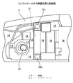
図1は、本発明に係る作業機械の冷却装置の配置状態を示す平面図であり、フードやカバーの図示を省略している。図2は、エンジンルームと冷却通路との間に構成した隔壁をエンジンルーム側から見た側面図であり、図3は、本発明に係る作業機械の冷却装置の概略的な配置関係を示す概略平面図である。 FIG. 1 is a plan view showing an arrangement state of a cooling device for a work machine according to the present invention, and illustration of a hood and a cover is omitted. FIG. 2 is a side view of a partition wall formed between the engine room and the cooling passage as viewed from the engine room side, and FIG. 3 is a schematic diagram illustrating a schematic arrangement relationship of the cooling device for the work machine according to the present invention. It is a top view.
エンジンルーム11は、作業機械10の前後方向に沿って配設されており、エンジンルーム11内には、エンジン12と、エンジン12の前方に配した冷却ファン14と、冷却ファン14の前方に配したラジエータ13及び作動油クーラ19等を、直列に配設している。また、エンジン12の上部部位におけるエンジンルーム11内には、過給機である排気ターボ過給機15が配設されている。
The
そして、エンジンルーム11の上方は、エンジンフード17(図2参照)により覆われている。エンジンフード17によって、エンジンフード17の上部における外気とエンジンフード17の内部におけるエンジンルーム11とを分けている。そして、エンジンフード17と、後述する隔壁18と、エンジンルーム11の下面板と、によって囲まれたエンジンルーム11は、作業機械10の前後方向に沿って空気が流通するように構成されている。
The upper portion of the
また、作業機械10は、エンジンルーム11の後方上部にキャブ23(図1参照)が搭載されており、エンジンルーム11の後方であって、キャブ23の下方の領域には、図示しない左右の前輪、トランスミッション、アクスル装置などが配置されている。
Further, the
エンジンルーム11と並列に並んで冷却通路20が、作業機械10の前後方向に沿って配設されている。エンジンルーム11と冷却通路20との間には、両室を画成する隔壁18が配設されている。冷却通路20は、図示しないアフタークーラカバーと隔壁18及び図示しない下面板とによって囲まれた構成となっており、アフタークーラカバー前方に設けた外気導入口から取り入れた空気が、後方に流通するように構成されている。そして、図2に示すように、隔壁18は、エンジンルーム11と冷却通路20との間で空気の流通が行われないように構成されている。
A
尚、アフタークーラカバーの構成としては、前述したエンジンルーム11の上方を覆うエンジンフード17と一体に構成されていても良い。逆に、後述する排ガス後処理装置としてのPMフィルタ装置までを一体的に覆った構成とする代わりに、空気の流通を阻害しない構造で、分割されている構成としておくこともできる。
The aftercooler cover may be configured integrally with the
また、隔壁18を構成する壁の一部としては、後述する冷却通路20内に配設したアフタークーラ21の側壁面を利用することもできる。アフタークーラ21の側壁面を利用せずに、壁だけでエンジンルーム11と冷却通路20との間を画成する隔壁18を構成としておくこともできる。隔壁18としては、完全にエンジンルーム11と冷却通路20との間を遮断する構成としておくことも、エンジンルーム11と冷却通路20との間を完全に遮断した構成とはせずに、エンジンルーム11と冷却通路20との間で多少の空気の出入りが行える隙間を有した構成としておくこともできる。
Further, as a part of the wall constituting the
隙間を有した構成とした場合であっても、エンジンルーム11内を流れる空気や冷却通路20内を流れる空気が、隙間から流入してきた空気によってかき乱されない程度の隙間として構成しておくことが望ましい。
Even in the case of a configuration having a gap, the air flowing in the
冷却通路20内には、エアークリーナ16、アフタークーラ21、アフタークーラ21を冷却する冷却ファン22、及び冷却ファン22からの廃熱風によってその周囲が冷却される排ガス後処理装置としてのPMフィルタ装置25が、直列に配設している。PMフィルタ装置25は、図示せぬ前輪の上方で、かつ、キャブ23の側方に配置されている。
In the
PMフィルタ装置25は、ディーゼルエンジンの排気ガスに含まれる粒子状物質を減少させる装置(フィルタ)であり、基本的な構成としては、粒子状物質をフィルタによって捕捉する装置となっている。図示例で示したPMフィルタ装置25には、フィルタが目詰まりしたときにフィルタ機能が低下するのを防止するため、フィルタに堆積した粒子状物質を燃焼させて、フィルタを再生させることのできるセルフ・クリーニング機能が設けられている。
The
エンジン12の前方に配した冷却ファン14としては、エンジン12に直結した構成としておくことも、アフタークーラ21の冷却ファン22と同様に、エンジン12駆動の図示せぬ油圧ポンプからの吐出圧によって駆動される油圧モータを用いて、同油圧モータによって駆動される構成としておくこともできる。あるいは、電動モータで駆動される構成としておくこともできる。
The cooling
冷却ファン14及び冷却ファン22を油圧モータで駆動する構成としておくことにより、ラジエータ13や作動油クーラ19等、アフタークーラ21の配置位置に対する自由度を高めることができる。また、冷却ファン14、冷却ファン22による冷却空気の流れとしては、図1に示すようにラジエータ13やアフタークーラ21に対しての吸込側の流れとして構成しておくことも、冷却ファン14、冷却ファン22をラジエータ13やアフタークーラ21の前面側に配して、吐出側の流れとして構成しておくこともできる。
By setting the cooling
ラジエータ13には、一対の配管29(図1では、一方の配管29のみを図示)が接続されており、エンジン12を冷却する冷却水の冷却を行うことができる。排気ターボ過給機15には、管路28を介して冷却通路20内に配したエアークリーナ16が接続されている。管路28は、図2に示すように隔壁18に形成して開口32を通って、エアークリーナ16に接続されるとともに、エンジンルーム11内において排気ターボ過給機15に接続している。
A pair of pipes 29 (only one
エアークリーナ16を介して吸い込まれた外気は、管路28を介して排気ターボ過給機15に供給され、排気ターボ過給機15では図示せぬコンプレッサによって過給状態にされる。過給状態となった後に、吸気管26aを介してアフタークーラ21に供給される構成となっている。図示せぬコンプレッサは、エンジン12から排出される排気ガスによって、回転駆動される。
The outside air sucked through the
アフタークーラ21で冷却された過給状態の空気(過給気ともいう。)は、吸気管26bを通り図示せぬ吸気マニホールドを介してエンジン12に吸入される。そして、燃料と混合されてエンジン12内での燃焼に用いられる。エンジン12から排出された排気ガスは、図示せぬ排気管を介して排気ターボ過給機15に導入される。排気ターボ過給機15に導入された排気ガスは、エアークリーナ16を介して吸い込まれた空気を過給状態にするコンプレッサを駆動するタービンの回転に用いられた後、排気管27を通ってPMフィルタ装置25に導入される。PMフィルタ装置25に導入された排気ガスは、フィルタによって粒子状物質であるPMを取り除いてから、外気に放出される。
The supercharged air (also referred to as supercharged air) cooled by the
アフタークーラ21に接続した吸気管26aが接続する排気ターボ過給機15の接続口及びアフタークーラ21に接続した吸気管26bが接続するエンジン12の吸気マニホールドの配設位置としては、隔壁18の近くに構成している。また、図2に示すように隔壁18には、開口33aと開口33bとが形成されている。開口33aは、排気ターボ過給機15に接続した吸気管26aをアフタークーラ21に接続するための開口として構成されており、開口33bは、アフタークーラ21で冷却された空気をエンジン12に供給する吸気管26bが通る開口として構成されている。
The
図1及び図3に示すように、アフタークーラ21の配設位置としては、エンジン12の配設位置の横に並んだ位置となっている。尚、図3では、冷却装置の概略的な配置関係を示している。
As shown in FIGS. 1 and 3, the position where the
このように構成しているので、エンジンルーム11内における吸気管26a、26bの配管長さをそれぞれ短く構成しておくことができる。また、この構成により、エンジンルーム11内における吸気管26a、26bの長さを短く構成しておくことができるようになるので、エンジンルーム11内の暖気によって吸気管26a、26b内を流れる空気が暖められてしまうのを防止しておくことができる。
With this configuration, the pipe lengths of the
しかも、エンジン12の配設位置の横にアフタークーラ21を配設した構成によって、作業機械10の稼動、例えば、悪路走行(片輪のみ乗り越しを行う走行)時に発生する衝撃や振動等の影響によって、車体フレームが振動したとしても、エンジン12とアフタークーラ21とは、同位相で捩れ運動を行ったり、同じように揺れることができる。
In addition, the configuration in which the
ところで、エンジン12は、出力を取り出す回転軸方向に細長く構成され、左右方向には短く構成されている(単気筒エンジンや星型エンジンを除く)。また、車体フレームの捩れや揺れによる影響は、重量物であるエンジン12がその影響を受け易くなっている。エンジン12の長手方向をエンジンルーム11の前後方向に配置し、その前後方向の中間位置の側方にアフタークーラ21を配する構成を採ることができると、アフタークーラ21の取付位置をよりエンジン12の重心位置に近づけて配置することができる。
By the way, the
このように、アフタークーラ21を配置することで、車体フレームの捩れや揺れによる影響が、アフタークーラ21に対して少なくすることができる。本発明では、エンジン12の配設位置の横にアフタークーラ21を配置することができるので、アフタークーラ21をエンジン12の前後方向の中間位置に配置することが可能となる。
Thus, by arranging the
このように、アフタークーラ21に接合している一対の吸気管26a、26bとの各接合部が、弛んでしまったり破損してしまったりすることを防止しておくことができる。従って、特別な支持手段を用いることなくアフタークーラに接合している一対の吸気管26a、26bの支持を行っておくことができる。
In this way, it is possible to prevent the joints between the pair of
エンジンルーム11と冷却通路20とは、隔壁18を介して画成された構成となっているので、エンジンルーム11内での空気の流れと、冷却通路20内での空気の流れとは、それぞれ独立した流れとして構成しておくことができる。しかも、作業機械の走行時には、作業機械10の走行を利用した走行風をエンジンルーム11内と冷却通路20内へ、それぞれ個別に導入することができる。
Since the
この構成により、冷却通路20内ではエンジンルーム11内での暖気の影響を受け難くなっており、アフタークーラ21に対する冷却効果、PMフィルタ装置25の外周面に対する冷却効果を高めておくことができる。
With this configuration, the
特に、冷却通路20を一種のダクトとして利用することができるので、冷却通路20内に導入される走行風、アフタークーラ21用の冷却ファン22で引き起こされる風量を、アフタークーラ21に対する冷却風、PMフィルタ装置25の外周面に対する冷却風として、有効に作用させることができる。
In particular, since the
これにより、PMフィルタ装置25の外周面を冷却しておくことで、PMフィルタ装置25の周辺に配設した図示せぬ機器に対する熱の影響を防止しておくことができ、また、PMフィルタ装置25に隣接して配したキャブ23内での温度上昇を抑えておくことができる。
Thus, by cooling the outer peripheral surface of the
しかも、エンジンルーム11内で発生した騒音は、隔壁18によって遮音しておくことができるので、エンジンルーム11内で発生した騒音が、冷却通路20を介して外部に漏れ出るのを防止しておくことができる。
In addition, since noise generated in the
本発明に係る冷却装置は、PMフィルタ装置を備えた作業機械に対して好適に適用することが可能である。 The cooling device according to the present invention can be suitably applied to a work machine provided with a PM filter device.
10・・・作業機械、11・・・エンジンルーム、12・・・エンジン、13・・・ラジエータ、15・・・排気ターボ過給機、18・・・隔壁、20・・・冷却通路、21・・・アフタークーラ、25・・・PMフィルタ装置、51・・・エンジンルーム、52・・・エンジン、53・・・冷却ファン、55・・・ラジエ−タ、56・・・ターボチャージャ、58・・・空冷アフタークーラ。
DESCRIPTION OF
Claims (2)
エンジンを格納するエンジンルームが、前記作業機械の前後方向に構成され、前記エンジンルーム内において、前記ラジエータ及び同ラジエータを冷却する冷却ファンと、前記エンジンとが、この順序で前記作業機械の前後方向に沿って配設され、
前記作業機械の前後方向に構成されて、前記エンジンルームと並列に配設された冷却通路が、隔壁を隔てて前記エンジンルームと画成され、
前記冷却通路内において、前記アフタークーラ及び同アフタークーラを冷却するアフタークーラ用冷却ファンと、排ガス後処理装置とが、この順序で前記作業機械の前後方向に沿って配設され、
前記アフタークーラが、前記エンジンの配設位置の横に並んで配設されてなることを特徴とする作業機械の冷却装置。 In a cooling device for a work machine comprising a radiator that cools engine cooling water and an aftercooler that cools air that has been supercharged by a supercharger,
An engine room for storing the engine is configured in the front-rear direction of the work machine. In the engine room, the radiator, a cooling fan for cooling the radiator, and the engine are arranged in this order in the front-rear direction of the work machine. Arranged along the
A cooling passage configured in the front-rear direction of the work machine and arranged in parallel with the engine room is defined as the engine room with a partition wall therebetween,
In the cooling passage, the aftercooler and an aftercooler cooling fan for cooling the aftercooler and the exhaust gas aftertreatment device are arranged in this order along the front-rear direction of the work machine,
A cooling device for a working machine, wherein the aftercooler is arranged side by side next to a position where the engine is arranged.
Priority Applications (1)
| Application Number | Priority Date | Filing Date | Title |
|---|---|---|---|
| JP2008265192A JP5066051B2 (en) | 2008-10-14 | 2008-10-14 | Work machine cooling system |
Applications Claiming Priority (1)
| Application Number | Priority Date | Filing Date | Title |
|---|---|---|---|
| JP2008265192A JP5066051B2 (en) | 2008-10-14 | 2008-10-14 | Work machine cooling system |
Publications (2)
| Publication Number | Publication Date |
|---|---|
| JP2010096014A true JP2010096014A (en) | 2010-04-30 |
| JP5066051B2 JP5066051B2 (en) | 2012-11-07 |
Family
ID=42257880
Family Applications (1)
| Application Number | Title | Priority Date | Filing Date |
|---|---|---|---|
| JP2008265192A Expired - Fee Related JP5066051B2 (en) | 2008-10-14 | 2008-10-14 | Work machine cooling system |
Country Status (1)
| Country | Link |
|---|---|
| JP (1) | JP5066051B2 (en) |
Cited By (4)
| Publication number | Priority date | Publication date | Assignee | Title |
|---|---|---|---|---|
| JP2012137002A (en) * | 2010-12-27 | 2012-07-19 | Suzuki Motor Corp | Cooling device for intercooler of vehicle |
| WO2014069026A1 (en) | 2012-10-30 | 2014-05-08 | 株式会社小松製作所 | Construction vehicle equipped with exhaust-gas post-processing device |
| US8985262B2 (en) | 2012-10-30 | 2015-03-24 | Komatsu Ltd. | Construction vehicle equipped with exhaust aftertreatment device |
| US10006646B2 (en) | 2015-04-30 | 2018-06-26 | Samsung Electronics Co., Ltd. | Outdoor unit of air conditioner and control device for the outdoor unit |
Citations (4)
| Publication number | Priority date | Publication date | Assignee | Title |
|---|---|---|---|---|
| JPH09125972A (en) * | 1995-11-08 | 1997-05-13 | Komatsu Ltd | Cooling device for hydraulic shovel |
| JPH11269918A (en) * | 1998-03-20 | 1999-10-05 | Shin Caterpillar Mitsubishi Ltd | Cooling device for construction machine |
| WO2007055644A1 (en) * | 2005-09-20 | 2007-05-18 | Scania Cv Ab (Publ) | Arrangement for recirculation of exhaust gases of a supercharged internal combustion engine |
| JP2007138872A (en) * | 2005-11-21 | 2007-06-07 | Mitsubishi Motors Corp | Cooling fan control system |
-
2008
- 2008-10-14 JP JP2008265192A patent/JP5066051B2/en not_active Expired - Fee Related
Patent Citations (4)
| Publication number | Priority date | Publication date | Assignee | Title |
|---|---|---|---|---|
| JPH09125972A (en) * | 1995-11-08 | 1997-05-13 | Komatsu Ltd | Cooling device for hydraulic shovel |
| JPH11269918A (en) * | 1998-03-20 | 1999-10-05 | Shin Caterpillar Mitsubishi Ltd | Cooling device for construction machine |
| WO2007055644A1 (en) * | 2005-09-20 | 2007-05-18 | Scania Cv Ab (Publ) | Arrangement for recirculation of exhaust gases of a supercharged internal combustion engine |
| JP2007138872A (en) * | 2005-11-21 | 2007-06-07 | Mitsubishi Motors Corp | Cooling fan control system |
Cited By (6)
| Publication number | Priority date | Publication date | Assignee | Title |
|---|---|---|---|---|
| JP2012137002A (en) * | 2010-12-27 | 2012-07-19 | Suzuki Motor Corp | Cooling device for intercooler of vehicle |
| WO2014069026A1 (en) | 2012-10-30 | 2014-05-08 | 株式会社小松製作所 | Construction vehicle equipped with exhaust-gas post-processing device |
| WO2014069038A1 (en) | 2012-10-30 | 2014-05-08 | 株式会社小松製作所 | Dumptruck |
| US8820468B2 (en) | 2012-10-30 | 2014-09-02 | Komatsu Ltd. | Dump truck |
| US8985262B2 (en) | 2012-10-30 | 2015-03-24 | Komatsu Ltd. | Construction vehicle equipped with exhaust aftertreatment device |
| US10006646B2 (en) | 2015-04-30 | 2018-06-26 | Samsung Electronics Co., Ltd. | Outdoor unit of air conditioner and control device for the outdoor unit |
Also Published As
| Publication number | Publication date |
|---|---|
| JP5066051B2 (en) | 2012-11-07 |
Similar Documents
| Publication | Publication Date | Title |
|---|---|---|
| CN102666174B (en) | Work vehicle | |
| KR101913981B1 (en) | Work vehicle | |
| US9394817B2 (en) | Cooling structure for urea aqueous solution conduit | |
| WO2014069038A1 (en) | Dumptruck | |
| EP3208125A1 (en) | Work vehicle | |
| US8827029B1 (en) | Bulldozer | |
| JP5328023B2 (en) | engine | |
| US20150068470A1 (en) | Ventilation structure for engine compartment | |
| JP2010106716A (en) | Heat-retaining/cooling control apparatus for pm filter device | |
| JP6295195B2 (en) | Work machine | |
| JP6137739B2 (en) | Work vehicle | |
| JP5066051B2 (en) | Work machine cooling system | |
| JP6275552B2 (en) | Work vehicle | |
| US9290907B2 (en) | Work vehicle | |
| JP6965601B2 (en) | Saddle-type vehicle | |
| JP6884833B2 (en) | Work machine | |
| JP6679676B2 (en) | Work machine | |
| JP6400520B2 (en) | Working machine | |
| JP2009150243A (en) | Turbocharged engine | |
| JP6742800B2 (en) | Excavator | |
| JPWO2014069038A1 (en) | Dump truck | |
| JP6613809B2 (en) | Saddle riding vehicle | |
| JP6295143B2 (en) | Tractor | |
| JP7173919B2 (en) | work vehicle | |
| JP2003193509A (en) | Cooling device in construction equipment |
Legal Events
| Date | Code | Title | Description |
|---|---|---|---|
| A621 | Written request for application examination |
Free format text: JAPANESE INTERMEDIATE CODE: A621 Effective date: 20110829 |
|
| A131 | Notification of reasons for refusal |
Free format text: JAPANESE INTERMEDIATE CODE: A131 Effective date: 20120515 |
|
| A977 | Report on retrieval |
Free format text: JAPANESE INTERMEDIATE CODE: A971007 Effective date: 20120517 |
|
| A521 | Written amendment |
Free format text: JAPANESE INTERMEDIATE CODE: A523 Effective date: 20120627 |
|
| TRDD | Decision of grant or rejection written | ||
| A01 | Written decision to grant a patent or to grant a registration (utility model) |
Free format text: JAPANESE INTERMEDIATE CODE: A01 Effective date: 20120807 |
|
| A01 | Written decision to grant a patent or to grant a registration (utility model) |
Free format text: JAPANESE INTERMEDIATE CODE: A01 |
|
| A61 | First payment of annual fees (during grant procedure) |
Free format text: JAPANESE INTERMEDIATE CODE: A61 Effective date: 20120810 |
|
| R150 | Certificate of patent or registration of utility model |
Ref document number: 5066051 Country of ref document: JP Free format text: JAPANESE INTERMEDIATE CODE: R150 Free format text: JAPANESE INTERMEDIATE CODE: R150 |
|
| FPAY | Renewal fee payment (event date is renewal date of database) |
Free format text: PAYMENT UNTIL: 20150817 Year of fee payment: 3 |
|
| LAPS | Cancellation because of no payment of annual fees |