JP2010095045A - Vehicle undercover and its fixing structure - Google Patents
Vehicle undercover and its fixing structure Download PDFInfo
- Publication number
- JP2010095045A JP2010095045A JP2008265506A JP2008265506A JP2010095045A JP 2010095045 A JP2010095045 A JP 2010095045A JP 2008265506 A JP2008265506 A JP 2008265506A JP 2008265506 A JP2008265506 A JP 2008265506A JP 2010095045 A JP2010095045 A JP 2010095045A
- Authority
- JP
- Japan
- Prior art keywords
- vehicle
- undercover
- under cover
- side wall
- under
- Prior art date
- Legal status (The legal status is an assumption and is not a legal conclusion. Google has not performed a legal analysis and makes no representation as to the accuracy of the status listed.)
- Granted
Links
Images


Abstract
Description
本発明は、車両用アンダーカバー及びその取付構造に係り、特に、車体下部での空気抵抗を低減させることを主な目的として、車体の床下を覆って配置される車両用アンダーカバーと、そのような車両用アンダーカバーを車両に対して有利に取り付けるための新規な構造とに関する。 The present invention relates to a vehicular undercover and its mounting structure, and more particularly to a vehicular undercover disposed so as to cover an under floor of a vehicle body, with the main purpose of reducing air resistance at the lower part of the vehicle body, and the like. The present invention relates to a novel structure for advantageously mounting a vehicle undercover on a vehicle.
よく知られているように、自動車等の車両では、車体表面に凹凸部が存在すると、走行時における車体表面での空気の円滑な流れが阻害されるようになり、それによって、空気抵抗が増大して、走行安定性が損なわれたり、或いは燃費が悪化する等の問題が惹起される。そこで、近年では、車体の側面や上面を、可及的に空気抵抗の小さな形状となるように設計するだけでなく、車体の床下をアンダーカバーにて覆うことによって、空気抵抗低減化の一層の促進が、図られている。 As is well known, in vehicles such as automobiles, if there are irregularities on the surface of the vehicle body, the smooth flow of air on the surface of the vehicle body during travel is inhibited, thereby increasing the air resistance. As a result, problems such as impaired running stability or worsened fuel efficiency are caused. Therefore, in recent years, not only designing the side and upper surface of the vehicle body to be as small as possible in the air resistance, but also covering the under floor of the vehicle body with an under cover further reduces the air resistance. Promotion is planned.
ところで、そのような車両用アンダーカバーを自動車等に取り付ける場合には、空力性能を更に向上させる上で、アンダーカバーの下面の位置がより低くされて、アンダーカバーの下面と地面との隙間が可及的に小さくされていることが、望ましい。 By the way, when such a vehicle under cover is attached to an automobile or the like, in order to further improve the aerodynamic performance, the position of the lower surface of the under cover is lowered to allow a gap between the lower surface of the under cover and the ground. It is desirable to make it as small as possible.
しかしながら、そうすると、例えば、駐車場に駐車する際、或いは路肩の縁石や段差に乗り上げた際等に、アンダーカバーが、タイヤ止めや縁石、段差に接触して、変形したり、破損したりして、アンダーカバーの空気抵抗低減機能が損なわれてしまう恐れがあった。また、アンダーカバーの形状が、自動車の床下に配置される様々な床下部材の下面に沿った形状とされている場合には、そのような床下部材も、アンダーカバーの変形によって、変形乃至は破損する事態が生ずる可能性があった。そして、かかる床下部材が、例えば、自動車の前部の下部部位に、前後方向に延びるように設置されて、前端部において、車両の前面に衝突した歩行者の脚部に接触することにより、かかる脚部を保護し得るように構成した歩行者保護装置であると、アンダーカバーの変形に伴う歩行者保護装置の変形乃至は損傷によって、歩行者の保護性能にまで支障を来すといった問題が惹起されるようになる。 However, if you do so, for example, when you park in a parking lot, or when you ride on a curb or step on the shoulder, the under cover may touch the tire stop, curb, or step and deform or break. The air resistance reducing function of the undercover may be impaired. In addition, when the shape of the undercover is a shape along the lower surface of various underfloor members arranged under the floor of the automobile, such underfloor member is also deformed or damaged by deformation of the undercover. There was a possibility that this would happen. And this underfloor member is installed, for example in the lower part of the front part of a car so that it may extend in the front-rear direction, and the front end part is brought into contact with the leg part of a pedestrian that has collided with the front of the vehicle. If the pedestrian protection device is configured to protect the legs, the pedestrian protection device may be deformed or damaged due to the deformation of the undercover, which may cause problems with the pedestrian protection performance. Will come to be.
そこで、下記特許文献1には、後側に向かって下傾する前面傾斜面部が設けられると共に、かかる前面傾斜面部の後側に、左右方向に延びる折れ線が形成された、弾性部材からなるアンダーカバーが、提案されている。このアンダーカバーでは、前面傾斜面部が、前方からの空気の流れを整流することで、空気抵抗の低減が図られている。また、そのような前面傾斜面部がタイヤ止め等の障害物に接触した際には、折れ線に沿って弾性変形し、タイヤ止め等との接触状態が解消したときに、復元し得るようになっており、それによって、アンダーカバーによる空気抵抗低減機能の損失が防止されるようになっている。 Therefore, in Patent Document 1 below, an under cover made of an elastic member is provided with a front inclined surface portion inclined downward toward the rear side, and a fold line extending in the left-right direction is formed on the rear side of the front inclined surface portion. Has been proposed. In this undercover, the front inclined surface portion rectifies the air flow from the front, thereby reducing air resistance. In addition, when such a front inclined surface portion comes into contact with an obstacle such as a tire stop, it is elastically deformed along the broken line, and can be restored when the contact state with the tire stop is eliminated. As a result, the loss of the air resistance reduction function due to the under cover is prevented.
ところが、そのような従来のアンダーカバーにおいては、その全体形状が、床下部材の下面に沿った形状とされているため、障害物との接触によるアンダーカバーの変形によって、床下部材が変形乃至は破損する事態が生ずる可能性が未だ否定出来なかった。しかも、かかるアンダーカバーでは、折れ線部に沿って確実に折れ曲がるように、折れ線部の周辺部分が、折れ線部を屈曲中心として、内側に「くの字」に屈曲した形状とされている。そのため、従来のアンダーカバーにあっては、樹脂材料を用いた金型成形によって成形される場合、折れ線部の周辺部分がアンダーカットとなって、成形性が低下するといった問題が内在していたのである。 However, since the overall shape of such a conventional undercover is a shape along the lower surface of the underfloor member, the underfloor member is deformed or damaged by deformation of the undercover due to contact with an obstacle. The possibility of a situation to occur still could not be denied. In addition, in such an undercover, the peripheral portion of the fold line portion is bent inwardly with the fold line portion as a bending center so as to be surely bent along the fold line portion. Therefore, in the case of the conventional under cover, when it is molded by molding using a resin material, there is an inherent problem that the peripheral portion of the broken line portion becomes an undercut and the moldability is lowered. is there.
ここにおいて、本発明は、上述せる如き事情を背景にして為されたものであって、その解決課題とするところは、車両の前部の床下に配置される床下部材を覆って車両に取り付けられる車両用アンダーカバーにおいて、車両への取付状態下での障害物との接触によるアンダーカバー自体の破損と、アンダーカバーによって覆われる床下部材の破損とが有利に防止されて、空気抵抗の低減機能が確実に且つ安定的に発揮され得ると共に、良好な成形性が確保され得るように改良された構造を提供することにある。また、本発明にあっては、そのような車両用アンダーカバーを車両に対して有利に取り付け得る新規な構造を提供することをも、その解決課題とするものである。 Here, the present invention has been made in the background as described above, and the problem to be solved is that the present invention covers the under-floor member disposed under the front floor of the vehicle and is attached to the vehicle. In the undercover for a vehicle, damage to the undercover itself due to contact with an obstacle when mounted on the vehicle and damage to the underfloor member covered by the undercover are advantageously prevented, and a function of reducing air resistance is provided. An object of the present invention is to provide an improved structure that can be reliably and stably exhibited and that good moldability can be secured. In addition, in the present invention, it is an object of the present invention to provide a novel structure in which such a vehicle under cover can be advantageously attached to a vehicle.
そして、本発明にあっては、上記した課題、又は本明細書全体の記載や図面から把握される課題を解決するために、以下に列挙せる如き各種の態様において、好適に実施され得るものである。また、以下に記載の各態様は、任意の組み合わせにおいても、採用可能である。なお、本発明の態様乃至は技術的特徴は、以下に記載のものに何等限定されることなく、明細書全体の記載並びに図面に開示の発明思想に基づいて、認識され得るものであることが、理解されるべきである。 And in the present invention, in order to solve the above-mentioned problems or the problems grasped from the entire description and drawings of the present specification, it can be suitably implemented in various modes as listed below. is there. Moreover, each aspect described below can be employed in any combination. It should be noted that aspects or technical features of the present invention are not limited to those described below, and can be recognized based on the description of the entire specification and the inventive concept disclosed in the drawings. Should be understood.
(1) 車両の前部の床下に配置される床下部材を覆って、車両の前後方向に延びるように位置せしめられた状態で、前部と後部とにおいて車両に取り付けられるアンダーカバーであって、下面を地面に近接位置させると共に、前記床下部材との間に空隙部を形成するための凹部を有し、且つ該凹部の前側側壁部の外面が、後方に向かって下傾する傾斜面とされ、更に、前端部と後端部のうちの少なくとも何れか一方に、前後方向に延びる、拡開可能な切込みが形成された、弾性部材にて構成したことを特徴とする車両用アンダーカバー。 (1) An undercover that is attached to a vehicle at a front portion and a rear portion in a state of covering an underfloor member disposed below the front floor of the vehicle and extending in the front-rear direction of the vehicle, The lower surface is positioned close to the ground and has a recess for forming a gap with the underfloor member, and the outer surface of the front side wall of the recess is an inclined surface inclined downward toward the rear. The vehicle undercover further comprises an elastic member in which at least one of the front end portion and the rear end portion is formed with an expandable cut extending in the front-rear direction.
(2) 前記切込みが、後端部のみに設けられている上記態様(1)に記載の車両用アンダーカバー。 (2) The vehicle under cover according to the aspect (1), wherein the cut is provided only in the rear end portion.
(3) 前記切込みが、前後方向の端縁から前記凹部の底壁部にまで達する長さを有している上記態様(1)又は(2)に記載の車両用アンダーカバー。 (3) The vehicle undercover according to the aspect (1) or (2), wherein the cut has a length that extends from an edge in the front-rear direction to a bottom wall portion of the recess.
(4) 前記凹部が後側側壁部を有し、且つ該後側側壁部の外面が、後部側に向かって上傾する傾斜面とされている上記態様(1)乃至(3)のうちの何れか一つに記載の車両用アンダーカバー。 (4) Of the above aspects (1) to (3), the concave portion has a rear side wall portion, and the outer surface of the rear side wall portion is an inclined surface inclined upward toward the rear side. The undercover for vehicles as described in any one.
(5) 車両の前部の床下に配置される床下部材を覆って車両の前後方向に延びるように位置せしめられた状態で、前部と後部とにおいて車両に取り付けられるアンダーカバーを車両に取り付けるための構造にして、上記態様(1)乃至(4)のうちの何れか一つに記載の車両用アンダーカバーを用い、該車両用アンダーカバーを、車両の前部の床下に、前記床下部材を覆い、且つ前記床下部材と前記凹部の底壁部との間に空隙部が形成されるように配置した状態で、前部と後部とにおいて、車両に取り付けることを特徴とする車両用アンダーカバーの取付構造。 (5) To attach an under cover attached to the vehicle at the front and the rear in a state where the vehicle is positioned so as to extend in the front-rear direction of the vehicle so as to cover an underfloor member disposed under the floor at the front of the vehicle The vehicle under cover according to any one of the above aspects (1) to (4) is used, the vehicle under cover is placed under the floor at the front of the vehicle, and the underfloor member is An undercover for a vehicle, wherein the vehicle undercover is attached to a vehicle at a front portion and a rear portion in a state where a space is formed between the underfloor member and the bottom wall portion of the recess. Mounting structure.
(6) 前記床下部材が、車両の前部の下部部位に、車両の前後方向に延びるように設置されて、前端部において、車両の前面に衝突した歩行者の脚部に接触することにより、該脚部を保護し得るように構成した車両用歩行者保護装置である上記態様(5)に記載の車両用アンダーカバーの取付構造。 (6) The underfloor member is installed at a lower part of the front portion of the vehicle so as to extend in the front-rear direction of the vehicle, and at the front end, by contacting the leg of the pedestrian that has collided with the front of the vehicle, The vehicle undercover attachment structure according to the above aspect (5), which is a vehicle pedestrian protection device configured to protect the leg portion.
すなわち、本発明に従う車両用アンダーカバーにあっては、その下面を地面に近接位置させるための凹部が設けられていることにより、下面の位置がより低くされて、下面と地面との間の隙間が可及的に小さくされている。そのため、アンダーカバーの下側を流れる空気の流速を増大させることが出来、それによって、かかるアンダーカバーが取り付けられる車両下部で生ずる空気抵抗を、より効果的に低減させることが可能となる。また、アンダーカバーに設けられた凹部の前側側壁部の外面が、後方に向かって下傾する傾斜面とされているところから、そのような傾斜面が、車両の床下を流れる気流を整流する機能を十分に発揮し、これによっても、車両下部での空力抵抗の低減を、更に有利に図ることが出来る。 That is, in the vehicle undercover according to the present invention, the recess is provided to position the lower surface of the vehicle under cover close to the ground, so that the position of the lower surface is lowered, and the gap between the lower surface and the ground is reduced. Is made as small as possible. Therefore, it is possible to increase the flow velocity of the air flowing under the under cover, thereby more effectively reducing the air resistance generated in the lower part of the vehicle to which the under cover is attached. Further, since the outer surface of the front side wall portion of the concave portion provided in the under cover is an inclined surface inclined downward toward the rear, such an inclined surface functions to rectify the airflow flowing under the floor of the vehicle. As a result, the aerodynamic resistance at the lower part of the vehicle can be reduced more advantageously.
また、本発明に係る車両用アンダーカバーは、弾性部材からなっている。そのため、例えば、かかるアンダーカバーが、車両への取付状態下で、タイヤ止め等の障害物と接触したときには、その接触部分が弾性変形せしめられ、そして、障害物との接触状態が解消されたときに、そのような弾性変形状態が復元される。これによって、接触部分での破損や破壊が有利に、回避され得る。しかも、本発明のアンダーカバーでは、それに設けられた凹部の内側の床下部材との間に空隙部が設けられている。それ故、アンダーカバーが、障害物との接触により弾性変形したときに、かかる変形部分の内面が、アンダーカバーによって覆われる床下部材に接触することが可及的に回避され得る。これにより、アンダーカバーの変形に伴って、床下部材が変形したり、破損したりすることが、効果的に防止され得る。 The vehicle under cover according to the present invention is made of an elastic member. Therefore, for example, when such an under cover comes into contact with an obstacle such as a tire stop under the state of being attached to the vehicle, the contact portion is elastically deformed, and the contact state with the obstacle is eliminated. Moreover, such an elastically deformed state is restored. This can advantageously avoid breakage or destruction at the contact portion. And in the undercover of this invention, the space | gap part is provided between the underfloor members inside the recessed part provided in it. Therefore, when the under cover is elastically deformed by contact with an obstacle, it can be avoided as much as possible that the inner surface of the deformed portion comes into contact with the underfloor member covered by the under cover. Thereby, it can prevent effectively that an underfloor member deform | transforms or breaks with a deformation | transformation of an undercover.
さらに、かかるアンダーカバーにおいては、前端部と後端部のうちの少なくとも何れか一方に、前後方向に延びる、拡開可能な切込みが設けられている。それ故、障害物との接触により弾性変形した際に、その変形量に応じた分だけ、切込みが拡開せしめられるようになる。それによって、かかる弾性変形時に、アンダーカバーの一部に応力集中が起きることが可及的に回避され、その結果、そのような応力集中の発生に起因して、耐久性が低下するようなことも、未然に防止され得る。そして、例えば、アンダーカバーが樹脂材料を用いた金型成形によって成形される場合にあっても、耐久性の向上に寄与する切込みを形成するために、アンダーカットの部分が生ずる等して、アンダーカバーの成形性が損なわれるようなことも、全くない。 Furthermore, in such an undercover, at least one of the front end portion and the rear end portion is provided with an expandable cut extending in the front-rear direction. Therefore, when elastically deforming due to contact with an obstacle, the incision can be expanded by an amount corresponding to the amount of deformation. As a result, stress concentration in a part of the undercover is avoided as much as possible during such elastic deformation, and as a result, durability is reduced due to the occurrence of such stress concentration. Can also be prevented in advance. For example, even when the undercover is formed by mold forming using a resin material, an undercut portion is formed to form a notch that contributes to improved durability. There is no possibility that the moldability of the cover is impaired.
従って、かくの如き本発明に従う車両用アンダーカバーにあっては、車両への取付状態下での障害物との接触によって破損を生ずることなく、十分な耐久性が有利に確保され得ると共に、かかる障害物との接触時における、アンダーカバーにて覆われる床下部材の破損も効果的に防止することが出来、以て、空気抵抗の低減機能が確実に且つ安定的に発揮され得るのであり、しかも、良好な成形性が十分に確保され得るのである。 Therefore, in the vehicle under cover according to the present invention as described above, sufficient durability can be advantageously ensured without causing damage due to contact with an obstacle in the mounted state on the vehicle. It is also possible to effectively prevent damage to the underfloor member covered with the undercover when in contact with an obstacle, and the function of reducing air resistance can be reliably and stably exerted. Good moldability can be sufficiently secured.
そして、本発明に従う車両用アンダーカバーの取付構造にあっても、上記せる車両用アンダーカバーにおいて奏される優れた作用・効果と実質的に同一の作用・効果が、極めて有利に享受され得るのである。 And, even with the vehicle undercover mounting structure according to the present invention, the substantially same operation and effect as the excellent operation and effect exhibited in the above vehicle undercover can be enjoyed extremely advantageously. is there.
以下、本発明を更に具体的に明らかにするために、本発明に係る車両用アンダーカバーの構成について、図面を参照しつつ、詳細に説明することとする。 Hereinafter, in order to clarify the present invention more specifically, the configuration of a vehicle undercover according to the present invention will be described in detail with reference to the drawings.
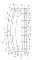
先ず図1及び図2には、本発明に従う構造を有する車両用アンダーカバーの一例として、自動車の前部の床下に配置される歩行者保護装置を覆って、取り付けられる自動車用アンダーカバーが、その上面形態と縦断面形態とにおいて、それぞれ概略的に示されている。それらの図から明らかなように、本実施形態のアンダーカバー10は、薄肉の板材からなっている。
First, in FIGS. 1 and 2, as an example of a vehicle undercover having a structure according to the present invention, an automobile undercover that covers and is attached to a pedestrian protection device disposed under a floor at the front of the automobile is shown. It is schematically shown in a top form and a longitudinal section form, respectively. As is clear from these drawings, the under
より具体的には、アンダーカバー10は、弾性体材料を用いて形成されている。このアンダーカバー10の形成に用いられる弾性体材料の種類としては、特に限定されるものではなく、例えば、ポリエチレン(PE)、ポリプロピレン(PP)等の弾性を有する公知の樹脂材料や、エチレン−プロピレン共重化合物(EPDM)等のゴム材料、或いは熱可塑性エラストマ等の弾性体材料が、挙げられる。また、それらの中でも、弾性を有する樹脂材料が軽量性の点から好適に用いられる。そして、一般には、それらの弾性体材料を用いた射出成形等を実施することによって、アンダーカバー10が、容易に成形される。
More specifically, the under
この射出成形品等からなるアンダーカバー10は、自動車の前部の下部部位への設置状態下で、図1の紙面左右方向(図2の紙面上下方向)に対応する横方向が、車体の前後方向となる一方、図1の紙面上下方向(図2中の紙面に垂直な方向)に対応する縦方向が、車体の幅方向となるように構成されている。そして、全体として、横長の矩形形状を呈している。また、このアンダーカバー10では、車体の前側に位置せしめられる前端面が、前方に向かって凸なる湾曲面形状とされている。なお、以下からは、原則として、アンダーカバー10の横方向(図1の紙面左右方向または車両前後方向)を前後方向と言い、また、アンダーカバー10の縦方向(図1の紙面上下方向または車両幅方向)を左右方向と言うこととする。
The under
かかるアンダーカバー10においては、その外周部を除く中央部に、凹部12が、比較的に深い深さを有して設けられている。そして、外周部には、周方向に連続して延びる外フランジ部14が、凹部12の側壁部の上端から外方に延び出すようにして、一体形成されている。
In such an undercover 10, a
このアンダーカバー10の中央部に設けられた凹部12は、左右方向に長い横長の矩形形状を呈する底壁部16と、かかる底壁部16の四つの辺縁部にそれぞれ立設された左側側壁部18と右側側壁部20と前側側壁部22と後側側壁部24の四つの側壁部とを有している。そして、それら底壁部16と四つの側壁部18〜24は、何れも薄肉の平板からなっており、また、上述の如く、それらの壁部を含むアンダーカバー10の全体が弾性体材料を用いて形成されている。これによって、底壁部16と四つの側壁部18〜24が、何れも、比較的に容易に弾性変形可能とされている。
The
また、凹部12の底壁部16は、その内面(上面)と外面(下面)とが、共に、水平に広がる、凹凸のない平坦面とされている。左側側壁部18と右側側壁部20も、共に、内面と外面とが上下方向に鉛直に延びる、凹凸のない平坦面とされている。これによって、アンダーカバー10の自動車への取付状態下で、自動車の下部を前方から後方に流れる気流に対する、アンダーカバー10の側面や下面での空気抵抗の低減が図られている。
In addition, the
そして、本実施形態では、凹部12の深さが比較的に深くされていることによって、つまり、左側及び右側側壁部18,20の高さが十分に高くされていることにより、アンダーカバー10の自動車への設置状態下で、アンダーカバー10の最下面を形成する底壁部16の外面の位置が、より低くされて、かかる底壁部16の外面と地面との隙間の大きさが可及的に小さくされている。なお、凹部16の具体的な深さは、特に限定されるものではないものの、ここでは、アンダーカバー10の自動車への取付状態下で、底壁部16の外面の地面からの高さが、140mm程度となるように設定されている。
And in this embodiment, when the depth of the recessed
また、凹部12が深い深さを有しているところから、アンダーカバー10の自動車への設置状態下で、凹部12の底壁部16が、自動車の床下に配置される床下部材(後述する図3に示されるように、本実施形態では、かかる床下部材が歩行者保護装置26からなる)と、単に非接触とされているだけでなく、凹部12の内側空間によって、凹部12の底壁部16と床下部材との間に、十分な大きさの空隙部28が形成されるようになっている(図3参照)。
In addition, since the
凹部12の後側側壁部24は、底壁部16の後側辺縁部から後方に向かって上傾する状態で、一体的に延び出した薄肉平板からなっている。このような後側側壁部24の外面(後面)が、後方に向かって上傾する傾斜面からなる摺動傾斜面30とされている。
The rear
前側側壁部22は、底壁部16の前側辺縁部から前方に向かって上傾する状態で、後側側壁部24よりも高い位置にまで一体的に延び出している。即ち、前側側壁部22は、後方に向かって下傾する傾斜面とされた外面部分を有しており、この外面部分が、アンダーカバー10の自動車への取付状態下で、アンダーカバー10の前側側壁部22の外面(前面)に衝突する空気をスムーズに後方を流すための整流面部32とされている。そして、この整流面部32は、前側側壁部22の上端部を除く大部分を占めて、後側側壁部24の外面よりも大きな面積を有しており、以て、より十分な整流作用を発揮し得るようになっている。また、前側側壁部22の整流面部32よりも上側の上端部には、凹部12の内側に屈曲する屈曲部34が設けられている。これによって、後側側壁部24よりも大きな前側側壁部22の強度の向上が図られている。
The front
一方、外フランジ部14は、前側側壁部22の上端から前方に向かって、水平に一体的に延び出す前側外フランジ部36と、後側側壁部24の上端から後方に向かって、水平に一体的に延び出す後側外フランジ部38と、左側側壁部18の上端から左側方に向かって、前側から後側に下傾した状態で、一体的に延び出しす左側外フランジ部40と、右側側壁部20の上端から右側方に向かって、前側から後側に下傾した状態で、一体的に延び出す右側外フランジ部42とからなっている。
On the other hand, the
それらのうち、前側外フランジ部36と後側外フランジ部38には、側板厚方向に貫通する、所定の固定ボルト等が挿通可能な挿通孔44が、左右方向に一定の間隔をおいて、それぞれ複数個(ここでは、前側外フランジ部36に5個、後側外フランジ部38に3個)設けられている。それら各挿通孔44は、前後方向に長く延びる長孔形状を有している。後述する如く、そのような各挿通孔18に挿通された固定ボルトによって、プレート部10が、自動車に取り付けられるようになっている。
Among them, the front
そして、本実施形態のアンダーカバー10においては、特に、後側外フランジ部38を含む後端部に対して、前後方向に真っ直ぐに延びる、切込みとしてのスリット46が、左右方向に一定の間隔をおいて複数(ここでは、6個)設けられている。それら各スリット46は、後側外フランジ部38の後端縁から、凹部12の後側側壁部24を経て、凹部12の底壁部16の後端部にまで達する長さと、狭い幅とを有して、後側外フランジ部38の複数の挿通孔44のうちの左右方向に互いに隣り合うもの同士の間に、それぞれ複数個(ここでは、3個)ずつ位置せしめられている。換言すれば、アンダーカバー10が、その後側部分の左右方向に一定の距離を隔てた複数の位置で、後端縁から凹部12の底壁部にまで達する長さにおいて切り込まれている。
And in the undercover 10 of this embodiment, the
かくして、かかるアンダーカバー10では、隣り合うスリット46同士の間に位置する後側部分のそれぞれが、各スリット46を、上下方向や左右方向、或いはそれらを組み合わせた様々な方向に拡開させつつ、比較的に容易に弾性変形する易変形部48とされている。具体的には、アンダーカバー10の自動車への取付状態下で、挿通孔44が設けられて自動車にボルト固定される易変形部48では、固定ボルトにて押さえ付けられる挿通孔44の周辺部分を除く部分が、また、挿通孔44を有しない易変形部48では、その全体が、それぞれ、スリット46を拡開させつつ、様々な方向に屈曲したり、湾曲したりして、弾性変形し得るようになっているのである。
Thus, in such an undercover 10, each of the rear portions located between the
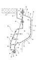
そして、かくの如き構造とされた本実施形態のアンダーカバー10は、例えば、図3に示されるような構造において、自動車の前部の下部部位に取り付けられる。
And the
すなわち、アンダーカバー10は、自動車の前部の下部部位に設置された歩行者保護装置26を下側から覆って位置せしめられた状態で、自動車に取り付けられる。より詳細には、歩行者保護装置26は、複数の補強リブ50が下方に向かって突出して、空気の流れを遮るような形態をもって一体形成されたプレート部52を有している。そして、このプレート部52が、その前端部を、図示しないフロントバンパのバンパカバー内に突入させた状態で、自動車の前後方向に延びるように配置されて、後端部において、ラジエータ54を支持するラジエータサポート56にボルト固定されており、以て、歩行者保護装置26が、自動車の前部の下部部位に取り付けられている。そうして、歩行者保護装置26にあっては、歩行者が自動車前面に接触乃至は衝突した際に、歩行者の脚部に対して、プレート部52の前面がバンパーカバーを介して接触し、そのときに、プレート部52で生ずる反力を歩行者の脚部に作用させることにより、歩行者をボンネット等の衝撃吸収可能な部材で(受け止めて)歩行者の保護及び安全が図られている。
That is, the under
そして、本実施形態のアンダーカバー10においては、前側外フランジ部36が、図示しないフロントバンパのバンパカバー内に突入して、歩行者保護装置26のプレート部52の前端部の下面と重なり合って、配置される一方、後側外フランジ部38が、歩行者保護装置26のプレート部52の後端部の下面と重なり合って、配置される。かくして、アンダーカバー10が、プレート部52と、プレート部52の下面に突設された、前方から後方への空気の流れを遮る各補強リブ50の全てを含む歩行者保護装置26の全体を、下側から覆って、位置せしめられる。また、それによって、アンダーカバー10の凹部12の底壁部16の内面(上面)と歩行者保護装置26の複数の補強リブ50の下端面(先端面)とが非接触とされた状態で、かかる歩行者保護装置26との間に、比較的に大きな容積を有する、凹部12の内側空間からなる空隙部28が、前後方向に延びるようにして、形成される。
In the
そして、そのような配置状態下で、前側外フランジ部36と後側外フランジ部38とにそれぞれ設けられた長孔からなる各挿通孔44の長さ方向の中央に、固定ボルト58がそれぞれ1個ずつ挿通され、更に、それら各固定ボルト58が、歩行者保護装置26のプレート部52の前端部と後端部とにそれぞれ設けられたボルト取付孔60に挿通されて、プレート部52に対して、ナット62により固定される。このとき、長孔からなる各挿通孔44の内周面の後端から固定ボルト58の脚部までの距離に応じた分と、各挿通孔44の内周面の前端から固定ボルト58の脚部までの距離に応じた分だけ、前側外フランジ部36や後側外フランジ部38の前方や後方への変位が許容され得る程度の締結力をもって、ナット62が固定ボルト58に締結される。これにより、アンダーカバー10が、歩行者保護装置26に固定され、この歩行者保護装置26を介して、自動車の前部の下部部位に対して、所定寸法だけ前後方向に変位可能な状態で取り付けられる。
And in such an arrangement | positioning state, the fixing
かくして、かくの如き取付構造において、自動車の前部の下部部位に取り付けられたアンダーカバー10にあっては、自動車の走行時に、自動車の下部を流れる空気が、凹部12の前側側壁部22に衝突するものの、図3に矢印:アにて示されるように、前側側壁部22の外面からなる整流面部32にて、空気を、整流面部32と凹部12の底壁部16の下面に沿って、スムーズに後方に流動させ得るようになっている。これによって、アンダーカバー10が取り付けられた自動車の前面での空気抵抗の低減が図られ、また、それが、凹部12の左側及び右側側壁部18,20の平坦面からなる外面と底壁部16の平坦面からなる下面とによる空気抵抗の低減作用と相俟って、自動車の前部の下部部位での空力性能が、極めて効果的に高められ得るのである。
Thus, in such an attachment structure, in the
また、かかるアンダーカバー10では、凹部12の深さが深くされていることで、凹部12の底壁部16の下面の位置が、より低くされて、かかる底壁部16の外面と地面との隙間の大きさが可及的に小さくされている。以て、アンダーカバー10が取り付けられた自動車の下側を流れる気流の速度が効果的に増大せしめられ、これによっても、自動車の前部の下部部位での空力性能が、より有利に高められ得る。
Further, in the
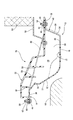
そして、本実施形態のアンダーカバー10にあっては、凹部12の底壁部16と四つの側壁部18〜24が、何れも容易に弾性変形可能とされている。それ故、アンダーカバー10が歩行者保護装置26を覆って前部の下部部位に取り付けられた自動車の前進時において、例えば、図4に示されるように、アンダーカバー10の前側側壁部22が、タイヤ止めや路肩の縁石、段差等の障害物64に接触した際に、図4に二点鎖線で示される如く、かかる前側側壁部22とそれに連続する底壁部16とが、凹部12の内側に凹まされるように弾性変形する。このとき、アンダーカバー10の障害物64との接触部位よりも後側部分が、衝突荷重により後方に押圧されて、長孔からなる各挿通孔44の内周面の前端から固定ボルト58の脚部までの距離に応じた分だけ、後方に変位する。そして、それと共に、図示されてはいないものの、アンダーカバー10の後側部分に設けられたスリット46の幾つかのものを拡開せしめつつ、易変形部48の幾つかのものが、様々な方向に屈曲又は湾曲するように弾性変形せしめられる。
And in the undercover 10 of this embodiment, the
このため、アンダーカバー10の前側側壁部22が障害物64と接触せしめられて、弾性変形した際に、アンダーカバー10のどこかの部分に応力集中が起きることが可及的に回避され、その結果、そのような応力集中の発生に起因して、アンダーカバー10が破損乃至は損傷するようなことが、有利に防止され得る。そして、そのようなアンダーカバー10の障害物64との接触状態から、自動車が後退すると、アンダーカバー10の弾性変形部分が復元されて、再び、アンダーカバー10の空気抵抗の低減機能が十分に発揮されるようになる。
For this reason, when the front
また、前側側壁部22の外面に設けられる整流面部32が、後方に向かって下傾する傾斜面にて構成されているため、自動車の前進時に前側側壁部22に接触した障害物に対して、前側側壁部22が、障害物64の表面に摺動しつつ、スムーズに弾性変形する。これによって、アンダーカバー10に生ずる応力の軽減が期待され得る。その上、アンダーカバー10の障害物64との接触状態から、自動車が後退するときに、弾性変形部分が、障害物64に引っ掛かってしまうようなことも、有利に回避され得る。
Moreover, since the rectification | straightening
さらに、アンダーカバー10が歩行者保護装置26を覆って前部の下部部位に取り付けられた自動車の後退時において、例えば、図5に示されるように、アンダーカバー10の後側側壁部24が、タイヤ止めや路肩の縁石、段差等の障害物64に接触した際には、図5に二点鎖線で示される如く、後側側壁部24とそれに連続する底壁部16とが、凹部12の内側に凹まされるように弾性変形する。そして、アンダーカバー10の前側側壁部22に障害物64が接触したときと同様に、アンダーカバー10の障害物64との接触部位よりも前側部分が、長孔からなる各挿通孔44の内周面の後端から固定ボルト58の脚部までの距離に応じた分だけ、前方に変位する。このとき、図示されてはいないものの、易変形部48の幾つかのものが、スリット46の幾つかのものを拡開させつつ、様々な方向に屈曲又は湾曲するように弾性変形せしめられる。かくして、アンダーカバー10の後側側壁部22の障害物64との接触に伴う弾性変形により、アンダーカバー10のどこかの部分に応力集中が起きることが可及的に回避され、以て、アンダーカバー10が破損乃至は損傷するようなことが、有利に防止され得る。そして、そのようなアンダーカバー10の障害物64との接触状態から、自動車が前進すると、アンダーカバー10の弾性変形部分が復元されて、再び、アンダーカバー10の空気抵抗の低減機能が十分に発揮されるようになる。
Furthermore, at the time of reversing of the automobile in which the undercover 10 covers the
また、後側側壁部24の外面が、後方に向かって上傾する摺動傾斜面部30とされているところから、自動車の後退時に後側側壁部24に接触した障害物に対して、後側側壁部24が、障害物64の表面に摺動しつつスムーズに弾性変形するようになり、それが、アンダーカバー10に生ずる応力の軽減の一助となる。更に、アンダーカバー10の障害物64との接触状態から、自動車が前進するときに、弾性変形部分が、障害物64に引っ掛かってしまうようなことも、有利に回避され得る。
Further, since the outer surface of the rear
しかも、アンダーカバー10とそれに覆われる歩行者保護装置26との間には、十分な大きさの空隙部28が設けられているため、アンダーカバー10の前側側壁部22の障害物64との接触時に、弾性変形せしめられた前側側壁部22部分や底壁部16部分が、歩行者保護装置26の下方に突出する補強リブ50等に接触して、かかる補強リブ50やそれが設けられるプレート部52等を変形させたり、破損させたりするようなことも、効果的に回避され得る。
In addition, since a sufficiently
従って、本実施形態のアンダーカバー10にあっては、十分な空気抵抗低減機能が、より有効に発揮され得ることに加えて、自動車への取付状態下での障害物64との衝突や接触によって破損を生ずることなく、十分な耐久性が有利に確保され得る。その結果、アンダーカバー10が取り付けられる自動車の下部の空力性能を、より長期に亘って、更に高いレベルで、安定的に維持させることが出来る。
Therefore, in the undercover 10 of the present embodiment, a sufficient air resistance reduction function can be exhibited more effectively, and in addition, due to a collision with or contact with an
また、かかるアンダーカバー10では、障害物64との接触による弾性変形に起因して、アンダーカバー10にて覆われる歩行者保護装置26を変形させたり破損させたりすることも効果的に防止出来、それによって、空力性能に加えて、歩行者保護性能も、安定的に維持することが出来る。
In addition, the undercover 10 can effectively prevent the
その上、本実施形態に係るアンダーカバー10においては、上記の如き空力性能の向上を図るために、単に、複数のスリット46が後側部分に設けられているだけであるため、例えば、アンダーカバー10を射出成形等の金型成形によって得る際にも、複数のスリット46を設けるために、アンダーカット部分が生ずるようなことがなく、それによって、良好な成形性が、有利に確保され得る。
Moreover, in the
また、かかるアンダーカバー10にあっては、歩行者保護装置26のプレート部52の下面から、空気の前方から後方への流れを遮るような形態で、一体的に突出形成された複数の補強リブ50の全てを下側から覆って配置されており、これによっても、自動車の下部での空力性能の向上が図られ得る。更に、複数の補強リブ50によって凹凸形態とされた歩行者保護装置26の下側部分を外部から目視出来ないように隠すことが出来るため、自動車の下部の見栄えを良好とするといった利点も得られる。
Further, in such an undercover 10, a plurality of reinforcing ribs integrally formed so as to block the flow of air from the front to the rear from the lower surface of the
さらに、本実施形態のアンダーカバー10では、複数のスリット46が、後端側部分に設けられているため、それら各スリット46が外部から容易に視認されることがない。それ故、スリット46の形成によるアンダーカバー10の見栄えの低下が惹起されることが、効果的に解消され得る。
Furthermore, in the
以上、本発明の具体的な構成について詳述してきたが、これはあくまでも例示に過ぎないのであって、本発明は、上記の記載によって、何等の制約をも受けるものではない。 The specific configuration of the present invention has been described in detail above. However, this is merely an example, and the present invention is not limited by the above description.
例えば、前記実施形態では、アンダーカバー10が、自動車の前部の床下に配置される床下部材たる歩行者保護装置26を覆って、自動車に取り付けられていたが、このアンダーカバー10にて覆われる床下部材は、歩行者保護装置26に、決して限られるものでないことは、勿論である。
For example, in the above-described embodiment, the under
また、アンダーカバー10の全体形状や、床下部材との間に形成される空隙部の形状等も、床下部材の形状等に応じて、適宜に変更され得るものである。 Further, the overall shape of the undercover 10 and the shape of the gap formed between the undercover member and the like can be changed as appropriate according to the shape of the underfloor member.
前記実施形態では、切込みが、アンダーカバー10の後側部分に設けられる狭幅のスリット46にて構成されていたが、かかる切込みは、アンダーカバーの弾性変形に伴って拡開されるものであれば、その形態が、特に限定されるものではない。従って、例えば、切込みを、幅の広いものとしたり、或いは実質的に幅を有しない、単なる線状の切込みによって構成することも出来る。
In the above-described embodiment, the incision is configured by the
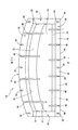
また、そのような切込みの形成位置も、例えば、図6に示されるように、アンダーカバー10の後端部に加えて、前端部に、スリット46として、左右方向に所定間隔を隔てて複数設けることも出来る。更に、図示されてはいないものの、後端部の切込みを省略して、前端部のみに設けることも、勿論可能である。なお、切込みは、図1や図6に示されるように、アンダーカバーを車両に取り付ける取付部(前記実施形態では、固定ボルトの挿通孔44)と、アンダーカバーの幅方向(アンダーカバーの車両への取付状態で車両の幅方向となる方向)に並んで配されるように設けられているか、若しくは、図示されていないものの、かかる取付部の形成位置よりも凹部12の底壁部16の前後方向中央部側に偏寄した位置に設けられていることが好ましい。それによって、アンダーカバーの障害物への接触時に、切込みが、より確実に拡開せしめられ得ることとなる。
Further, for example, as shown in FIG. 6, a plurality of such cut formation positions are provided as
切込みたる各スリット46の長さも、例えば、各スリット46が後側部分のみに設けられる場合において、後側外フランジ部38のみに止まる長さとしたり、後側外フランジ部38から後側側壁部24までの長さとしたりして、底壁部16までに達しない長さとされていても、何等差し支えない。
For example, when each slit 46 is provided only in the rear portion, the length of each slit 46 to be cut is a length that stops only at the rear
前側側壁部22の外面からなる整流面部32や後側側壁部24の外面からなる摺動傾斜面部30のそれぞれの傾斜角度、或いは凹部12の深さ等も、特に限定されるものでないことは、言うまでもないところである。
The inclination angle of each of the rectifying
加えて、本発明は、自動車の前部の床下に取り付けられるアンダーカバーと、かかるアンダーカバーの自動車への取付構造の他、自動車以外の車両の前部の床下に取り付けられる車両用アンダーカバーと、かかる車両用アンダーカバーの車両への取付構造の何れに対しても、有利に適用され得るものであることは、勿論である。 In addition, the present invention includes an under cover attached to the under floor of the front portion of the automobile, a vehicle under cover attached to the under floor of the front portion of a vehicle other than the automobile, in addition to a structure for attaching the under cover to the automobile, Of course, the present invention can be advantageously applied to any structure for mounting the vehicle undercover to the vehicle.
以上、本発明の具体的な構成について詳述してきたが、これはあくまでも例示に過ぎないのであって、本発明は、各種の形態において実施され得るものである。従って、当業者の知識に基づいて採用される本発明についての種々なる変更、修正、改良に係る各種の実施の形態が、何れも、本発明の趣旨を逸脱しない限りにおいて、本発明の範疇に属するものであることが、理解されるべきである。 The specific configuration of the present invention has been described in detail above. However, this is merely an example, and the present invention can be implemented in various forms. Accordingly, various embodiments relating to various changes, modifications, and improvements of the present invention adopted based on the knowledge of those skilled in the art are all within the scope of the present invention without departing from the spirit of the present invention. It should be understood that it belongs.
10 アンダーカバー 12 凹部
16 底壁部 22 前側側壁部
24 後側側壁部 26 歩行者保護装置
28 空隙部 30 摺動傾斜面部
32 整流面部 46 スリット
48 易変形部 64 障害物
DESCRIPTION OF
Claims (6)
下面を地面に近接位置させると共に、前記床下部材との間に空隙部を形成するための凹部を有し、且つ該凹部の前側側壁部の外面が、後方に向かって下傾する傾斜面とされ、更に、前端部と後端部のうちの少なくとも何れか一方に、前後方向に延びる、拡開可能な切込みが形成された、弾性部材にて構成したことを特徴とする車両用アンダーカバー。 An under cover that is attached to the vehicle at the front and rear portions in a state of covering the under-floor member disposed below the front floor of the vehicle and positioned to extend in the front-rear direction of the vehicle,
The lower surface is positioned close to the ground and has a recess for forming a gap with the underfloor member, and the outer surface of the front side wall of the recess is an inclined surface inclined downward toward the rear. The vehicle undercover further comprises an elastic member in which at least one of the front end portion and the rear end portion is formed with an expandable cut extending in the front-rear direction.
請求項1乃至請求項4のうちの何れか1項に記載の車両用アンダーカバーを用い、該車両用アンダーカバーを、車両の前部の床下に、前記床下部材を覆い、且つ前記床下部材と前記凹部の底壁部との間に空隙部が形成されるように配置した状態で、前部と後部とにおいて、車両に取り付けることを特徴とする車両用アンダーカバーの取付構造。 A structure for attaching an under cover attached to the vehicle at the front part and the rear part to the vehicle in a state of covering the under-floor member arranged under the floor at the front part of the vehicle and extending in the front-rear direction of the vehicle. And
A vehicle undercover according to any one of claims 1 to 4, wherein the vehicle undercover is covered under the floor of a front portion of the vehicle, covers the underfloor member, and the underfloor member. A mounting structure for an undercover for a vehicle, wherein the mounting structure is attached to a vehicle at a front portion and a rear portion in a state where a gap portion is formed between the bottom wall portion of the concave portion.
The underfloor member is installed at a lower portion of the front portion of the vehicle so as to extend in the front-rear direction of the vehicle, and comes into contact with the leg portion of the pedestrian that has collided with the front surface of the vehicle at the front end portion. The vehicle undercover mounting structure according to claim 5, which is a vehicle pedestrian protection device configured to protect the vehicle.
Priority Applications (1)
| Application Number | Priority Date | Filing Date | Title |
|---|---|---|---|
| JP2008265506A JP5244530B2 (en) | 2008-10-14 | 2008-10-14 | Undercover for vehicle and its mounting structure |
Applications Claiming Priority (1)
| Application Number | Priority Date | Filing Date | Title |
|---|---|---|---|
| JP2008265506A JP5244530B2 (en) | 2008-10-14 | 2008-10-14 | Undercover for vehicle and its mounting structure |
Publications (2)
| Publication Number | Publication Date |
|---|---|
| JP2010095045A true JP2010095045A (en) | 2010-04-30 |
| JP5244530B2 JP5244530B2 (en) | 2013-07-24 |
Family
ID=42257047
Family Applications (1)
| Application Number | Title | Priority Date | Filing Date |
|---|---|---|---|
| JP2008265506A Active JP5244530B2 (en) | 2008-10-14 | 2008-10-14 | Undercover for vehicle and its mounting structure |
Country Status (1)
| Country | Link |
|---|---|
| JP (1) | JP5244530B2 (en) |
Cited By (7)
| Publication number | Priority date | Publication date | Assignee | Title |
|---|---|---|---|---|
| JP2012081856A (en) * | 2010-10-12 | 2012-04-26 | Nissan Motor Co Ltd | Vehicle front structure |
| JP2012148655A (en) * | 2011-01-18 | 2012-08-09 | Nippon Plast Co Ltd | Under cover |
| CN103079900A (en) * | 2010-10-08 | 2013-05-01 | 日产自动车株式会社 | Bumper for vehicle |
| JP2015058779A (en) * | 2013-09-18 | 2015-03-30 | スズキ株式会社 | Undercover fitting structure |
| JP2016049877A (en) * | 2014-08-29 | 2016-04-11 | トヨタ自動車株式会社 | Underfloor cover for vehicle |
| JP2020111175A (en) * | 2019-01-11 | 2020-07-27 | トヨタ自動車株式会社 | Vehicular cover member |
| CN114044057A (en) * | 2021-11-30 | 2022-02-15 | 东风商用车有限公司 | Spoiler mounting structure |
Citations (5)
| Publication number | Priority date | Publication date | Assignee | Title |
|---|---|---|---|---|
| JPH04133990U (en) * | 1991-06-05 | 1992-12-14 | マツダ株式会社 | Vehicle undercover mounting structure |
| JP2001018852A (en) * | 1999-07-06 | 2001-01-23 | Honda Motor Co Ltd | Under cover |
| JP2005138690A (en) * | 2003-11-05 | 2005-06-02 | Kanto Auto Works Ltd | Front structure of automobile |
| JP3853111B2 (en) * | 1999-07-12 | 2006-12-06 | 本田技研工業株式会社 | Aerodynamic structure for front wheels |
| JP2008013013A (en) * | 2006-07-05 | 2008-01-24 | Mazda Motor Corp | Tire deflector of automobile |
-
2008
- 2008-10-14 JP JP2008265506A patent/JP5244530B2/en active Active
Patent Citations (5)
| Publication number | Priority date | Publication date | Assignee | Title |
|---|---|---|---|---|
| JPH04133990U (en) * | 1991-06-05 | 1992-12-14 | マツダ株式会社 | Vehicle undercover mounting structure |
| JP2001018852A (en) * | 1999-07-06 | 2001-01-23 | Honda Motor Co Ltd | Under cover |
| JP3853111B2 (en) * | 1999-07-12 | 2006-12-06 | 本田技研工業株式会社 | Aerodynamic structure for front wheels |
| JP2005138690A (en) * | 2003-11-05 | 2005-06-02 | Kanto Auto Works Ltd | Front structure of automobile |
| JP2008013013A (en) * | 2006-07-05 | 2008-01-24 | Mazda Motor Corp | Tire deflector of automobile |
Cited By (11)
| Publication number | Priority date | Publication date | Assignee | Title |
|---|---|---|---|---|
| CN103079900A (en) * | 2010-10-08 | 2013-05-01 | 日产自动车株式会社 | Bumper for vehicle |
| JP2012081856A (en) * | 2010-10-12 | 2012-04-26 | Nissan Motor Co Ltd | Vehicle front structure |
| JP2012148655A (en) * | 2011-01-18 | 2012-08-09 | Nippon Plast Co Ltd | Under cover |
| JP2015058779A (en) * | 2013-09-18 | 2015-03-30 | スズキ株式会社 | Undercover fitting structure |
| JP2016049877A (en) * | 2014-08-29 | 2016-04-11 | トヨタ自動車株式会社 | Underfloor cover for vehicle |
| JP2020111175A (en) * | 2019-01-11 | 2020-07-27 | トヨタ自動車株式会社 | Vehicular cover member |
| CN111483411A (en) * | 2019-01-11 | 2020-08-04 | 丰田自动车株式会社 | Cover member for vehicle |
| JP7139961B2 (en) | 2019-01-11 | 2022-09-21 | トヨタ自動車株式会社 | Vehicle cover member |
| CN111483411B (en) * | 2019-01-11 | 2023-09-22 | 丰田自动车株式会社 | Cover member for vehicle |
| CN114044057A (en) * | 2021-11-30 | 2022-02-15 | 东风商用车有限公司 | Spoiler mounting structure |
| CN114044057B (en) * | 2021-11-30 | 2022-10-14 | 东风商用车有限公司 | Spoiler mounting structure |
Also Published As
| Publication number | Publication date |
|---|---|
| JP5244530B2 (en) | 2013-07-24 |
Similar Documents
| Publication | Publication Date | Title |
|---|---|---|
| JP5244530B2 (en) | Undercover for vehicle and its mounting structure | |
| EP2237991B1 (en) | Tray energy absorber and bumper system | |
| US8449021B2 (en) | Vehicle lower-leg protection device and method of making and using the same | |
| US8998293B2 (en) | Airflow control device for an automotive vehicle | |
| JP6350482B2 (en) | Car deflector structure | |
| JP4890113B2 (en) | Pedestrian protection device for vehicles | |
| JP4908239B2 (en) | Pedestrian protection device for vehicles | |
| JP2004521813A (en) | Car front with bumper unit | |
| JP2007331455A (en) | Pedestrian protection device for vehicle | |
| JP2006506277A (en) | Integrated single bumper beam | |
| JP2009515773A (en) | Energy absorbing vehicle fender | |
| US8807629B2 (en) | Air dam | |
| JP5847502B2 (en) | Pedestrian protection device for vehicles | |
| JP6336884B2 (en) | Car wind guide parts, under cover and wind guide duct | |
| US20130015011A1 (en) | Pedestrian protection apparatus for vehicle | |
| WO2023207608A1 (en) | Bumper bracket, vehicle body front end assembly, and vehicle | |
| JP2008260401A (en) | Deflector fitting structure | |
| JP3508607B2 (en) | Shock absorbing bumper structure | |
| JP2012076536A (en) | Pedestrian protecting device for vehicle | |
| KR100820425B1 (en) | Energy absorber of bumper for vehicle | |
| JP2013023177A (en) | Cowl grille structure of vehicle | |
| JP5569338B2 (en) | Aerodynamic equipment for vehicles | |
| CN220594852U (en) | Front lower guard board and vehicle | |
| JP7322677B2 (en) | vehicle undercarriage | |
| JP2009286322A (en) | Cowl louver |
Legal Events
| Date | Code | Title | Description |
|---|---|---|---|
| A621 | Written request for application examination |
Free format text: JAPANESE INTERMEDIATE CODE: A621 Effective date: 20111004 |
|
| A977 | Report on retrieval |
Free format text: JAPANESE INTERMEDIATE CODE: A971007 Effective date: 20121220 |
|
| A131 | Notification of reasons for refusal |
Free format text: JAPANESE INTERMEDIATE CODE: A131 Effective date: 20121225 |
|
| A521 | Request for written amendment filed |
Free format text: JAPANESE INTERMEDIATE CODE: A523 Effective date: 20130225 |
|
| TRDD | Decision of grant or rejection written | ||
| A01 | Written decision to grant a patent or to grant a registration (utility model) |
Free format text: JAPANESE INTERMEDIATE CODE: A01 Effective date: 20130402 |
|
| A61 | First payment of annual fees (during grant procedure) |
Free format text: JAPANESE INTERMEDIATE CODE: A61 Effective date: 20130408 |
|
| FPAY | Renewal fee payment (event date is renewal date of database) |
Free format text: PAYMENT UNTIL: 20160412 Year of fee payment: 3 |
|
| R150 | Certificate of patent or registration of utility model |
Free format text: JAPANESE INTERMEDIATE CODE: R150 Ref document number: 5244530 Country of ref document: JP Free format text: JAPANESE INTERMEDIATE CODE: R150 |
|
| R250 | Receipt of annual fees |
Free format text: JAPANESE INTERMEDIATE CODE: R250 |
|
| R250 | Receipt of annual fees |
Free format text: JAPANESE INTERMEDIATE CODE: R250 |
|
| R250 | Receipt of annual fees |
Free format text: JAPANESE INTERMEDIATE CODE: R250 |
|
| R250 | Receipt of annual fees |
Free format text: JAPANESE INTERMEDIATE CODE: R250 |
|
| R250 | Receipt of annual fees |
Free format text: JAPANESE INTERMEDIATE CODE: R250 |
|
| R250 | Receipt of annual fees |
Free format text: JAPANESE INTERMEDIATE CODE: R250 |
|
| R250 | Receipt of annual fees |
Free format text: JAPANESE INTERMEDIATE CODE: R250 |
|
| R250 | Receipt of annual fees |
Free format text: JAPANESE INTERMEDIATE CODE: R250 |