JP2010094701A - Method of laser welding metal plated plate - Google Patents
Method of laser welding metal plated plate Download PDFInfo
- Publication number
- JP2010094701A JP2010094701A JP2008266687A JP2008266687A JP2010094701A JP 2010094701 A JP2010094701 A JP 2010094701A JP 2008266687 A JP2008266687 A JP 2008266687A JP 2008266687 A JP2008266687 A JP 2008266687A JP 2010094701 A JP2010094701 A JP 2010094701A
- Authority
- JP
- Japan
- Prior art keywords
- laser beam
- metal
- laser
- path
- plate
- Prior art date
- Legal status (The legal status is an assumption and is not a legal conclusion. Google has not performed a legal analysis and makes no representation as to the accuracy of the status listed.)
- Granted
Links
Images


Landscapes
- Laser Beam Processing (AREA)
Abstract
Description
本発明は、複数枚の金属メッキ板の重ね合わせ部分をレーザー溶接する方法に関する。 The present invention relates to a method for laser welding an overlapping portion of a plurality of metal plated plates.
亜鉛メッキ鋼板は母材金属板である鋼板の表面に防錆用の亜鉛メッキを施した鋼板材であり、自動車の車体の構造材等として多用されている。車体等を形成する場合に、2枚の亜鉛メッキ鋼板を重ね合わせて、その重ね合わせ部分にレーザービームを照射して、鋼板材を溶融、結合させるレーザー溶接法が知られている。(特許文献1−3を参照) A galvanized steel sheet is a steel sheet material in which the surface of a steel sheet, which is a base metal sheet, is galvanized for rust prevention, and is often used as a structural material for automobile bodies. In the case of forming a vehicle body or the like, a laser welding method is known in which two galvanized steel plates are overlapped and a laser beam is irradiated to the overlapped portion to melt and bond the steel plate materials. (See Patent Documents 1-3)
上記レーザー溶接を行うと、亜鉛の沸点(約900℃)が鋼板(鉄)の融点(約1500℃)より低いことに起因して溶接欠陥が発生することが知られている。つまり、レーザービームを前記重ね合わせ部分に照射することにより、鋼板が溶融するが、この時、重ね面の亜鉛が蒸発する。そして、亜鉛蒸気は溶融した鋼板内を通って外に抜けようとする。その結果、溶融した鋼板の一部が吹き飛ばされたり、一部の亜鉛蒸気が鋼板内部に残り、ブローホールと呼ばれる気孔を形成して、溶接強度を劣化させたり、外観が悪くなる。 When the laser welding is performed, it is known that welding defects occur due to the boiling point of zinc (about 900 ° C.) being lower than the melting point of steel plate (iron) (about 1500 ° C.). That is, by irradiating the overlapped portion with a laser beam, the steel sheet is melted, but at this time, zinc on the overlapped surface evaporates. And, zinc vapor tends to escape outside through the molten steel sheet. As a result, a part of the molten steel sheet is blown away, or a part of the zinc vapor remains inside the steel sheet, forming pores called blow holes, deteriorating the welding strength or worsening the appearance.
このような観点から、亜鉛メッキ鋼板のレーザー溶接法においては様々な対策が提案されている。(特許文献1−3を参照)例えば、特許文献1においては、エネルギー密度が低いレーザービームで亜鉛を蒸発、離散させた後、エネルギー密度が高いレーザービームで溶接接合させる方法が記載されている。また、特許文献1の方法においては、1つのレーザービームを、ハーフミラーと反射鏡を用いて、エネルギー密度が低いレーザービームとエネルギー密度が高いレーザービームとに分割し、それらの2つのレーザービームを、照射領域をずらして同時に照射するというものである。(特許文献1の図8等を参照)
しかしながら、特許文献1の溶接方法では、エネルギー密度が低いレーザービームとエネルギー密度が高いレーザービームとを同時照射しているので、以下の問題があった。 However, the welding method disclosed in Patent Document 1 has the following problems because the laser beam having a low energy density and the laser beam having a high energy density are simultaneously irradiated.
第1に、2つのレーザービームの移動速度が必然的に同一にならざるを得ず、このことが、亜鉛の蒸発と溶接接合という2つの過程を最適化する上で制約条件になるという問題がある。第2に、溶接しようとする経路が曲線の場合、2つの分割されたレーザービームの射出位置が異なることから、経路にずれを生じ易く、経路にずれが生じると溶接強度の劣化等の溶接欠陥を招くという問題がある。 First, the moving speeds of the two laser beams must be the same, and this is a problem in optimizing the two processes of zinc evaporation and welding. is there. Secondly, if the path to be welded is a curve, the two split laser beam emission positions are different, so that the path is likely to be displaced, and if the path is displaced, welding defects such as deterioration of the welding strength are caused. There is a problem of inviting.
請求項1に係る発明は、母材金属板の表面に母材金属の融点よりも低い沸点を有した金属をメッキしてなる、複数枚の金属メッキ板を重ね合わせ、重ね合わせ部にレーザービームを照射して溶接を行う金属メッキ板のレーザー溶接方法において、前記重ね合わせ部上の互いに隣接した第1乃至第3の経路に沿って、エネルギー密度が低く、且つ広い照射領域を有した第1のレーザービームを移動させながら照射することにより、前記広い照射領域の母材金属部分にメッキされた金属を蒸発、脱気させ、前記第1のレーザービームを前記第1乃至第3の経路に沿って照射した後に、前記第1及び第3の経路に挟まれた前記第2の経路に沿って前記第1のレーザービームよりもエネルギー密度が高く、且つ前記第1のレーザービームよりも狭い照射領域を有した第2のレーザービームを移動させながら照射することにより、前記狭い照射領域の母材金属部分を溶融して、溶接接合させることを特徴とする。 According to the first aspect of the present invention, a plurality of metal plated plates, which are obtained by plating a surface of a base metal plate with a metal having a boiling point lower than the melting point of the base metal, are overlapped, and a laser beam is applied to the overlap portion. In the laser welding method of a metal plated plate for performing welding by irradiating with a first energy line having a low energy density and a wide irradiation region along the first to third paths adjacent to each other on the overlapping portion. By irradiating while moving the laser beam, the metal plated on the base metal portion in the wide irradiation region is evaporated and degassed, and the first laser beam is passed along the first to third paths. After irradiation, the energy density is higher than that of the first laser beam along the second path sandwiched between the first and third paths, and is narrower than that of the first laser beam. By irradiating while moving the second laser beam having a region, to melt the base metal portion of the narrow irradiation region, characterized thereby welded.
上記構成によれば、第1のレーザービームを照射した後に、第2のレーザービームを照射するので、第1及び第2のレーザービーム線の移動速度を独立に制御することができる。その結果溶接条件の最適化が容易になる。また、第1及び第2のレーザービームの移動する経路のずれを無くすことができる。 According to the above configuration, since the second laser beam is irradiated after the first laser beam is irradiated, the moving speeds of the first and second laser beam lines can be controlled independently. As a result, optimization of welding conditions is facilitated. In addition, it is possible to eliminate the shift of the travel path of the first and second laser beams.
また、第1のレーザービームを第1乃至第3の経路に沿って照射した後に、第2のレーザービームを第1及び第3の経路に挟まれた第2の経路に沿って照射しているので第2のレーザービームの照射時には、第2の経路の両側を含めた広い範囲でメッキされた金属は既に蒸発、脱気されていることになる。これにより、金属蒸気の影響を無くして更に良好な溶接を実現することができる。ここで、第1乃至第3の経路は、直線経路でも円周経路でも良い。 In addition, after the first laser beam is irradiated along the first to third paths, the second laser beam is irradiated along the second path sandwiched between the first and third paths. Therefore, when the second laser beam is irradiated, the metal plated in a wide range including both sides of the second path has already been evaporated and degassed. Thereby, the influence of metal vapor can be eliminated and a better welding can be realized. Here, the first to third paths may be linear paths or circumferential paths.
また、請求項4に係る発明は、母材金属板の表面に母材金属の融点よりも低い沸点を有した金属をメッキしてなる、複数枚の金属メッキ板を重ね合わせ、重ね合わせ部にレーザービームを照射して溶接を行う金属メッキ板のレーザー溶接方法において、前記重ね合わせ部上における螺旋経路に沿って、エネルギー密度が低く、且つ広い照射領域を有した第1のレーザービームを移動させながら照射することにより、前記広い照射領域の母材金属部分にメッキされた金属を蒸発させ、前記第1のレーザービームを螺旋経路の全体に沿って照射した後に、前記螺旋経路の中でその両側の領域に前記第1のレーザービームの照射が行われた経路に沿って、前記第1のレーザービームよりもエネルギー密度が高く、且つ前記第1のレーザービームよりも狭い照射領域を有した第2のレーザービームを移動させながら照射することにより、前記狭い照射領域の母材金属部分を溶融して、溶接接合させることを特徴とする。 According to a fourth aspect of the present invention, a plurality of metal plated plates are formed by plating a metal having a boiling point lower than the melting point of the base metal on the surface of the base metal plate, and the overlap portion is formed. In the laser welding method of a metal plating plate for performing welding by irradiating a laser beam, the first laser beam having a low energy density and a wide irradiation area is moved along the spiral path on the overlapping portion. The metal plated on the base metal portion of the wide irradiation area is evaporated by irradiating the first laser beam along the entire spiral path, and then the both sides in the spiral path. The energy density of the region is higher than that of the first laser beam along the path where the first laser beam is irradiated to the region, and the region is higher than that of the first laser beam. By irradiating while moving the second laser beam having a narrow irradiation area, melting the parent metal portion of the narrow irradiation region, characterized thereby welded.
本発明によれば、請求項1の発明と同様に、第1のレーザービームを照射した後に、第2のレーザービームを照射するので、第1及び第2のレーザービーム線の移動速度を独立に制御することができる、その結果溶接条件の最適化が容易になる。また、第1及び第2のレーザービームの移動する経路のずれを無くすことができる。更に、第1のレーザービームを螺旋経路に沿って照射しているので、レーザービームの連続照射が可能となり、生産性を向上させることができる。また、第2のレーザービームの照射の時には、照射する経路の両側を含めた広い範囲でメッキされた金属が既に蒸発、脱気されている。これにより、請求項1に係る発明と同様、金属蒸気の影響を無くして更に良好な溶接を実現することができる。 According to the present invention, since the second laser beam is irradiated after the first laser beam is irradiated as in the first aspect of the invention, the moving speeds of the first and second laser beam lines can be set independently. Can be controlled, and as a result, optimization of welding conditions is facilitated. In addition, it is possible to eliminate the shift of the travel path of the first and second laser beams. Furthermore, since the first laser beam is irradiated along the spiral path, the laser beam can be continuously irradiated, and productivity can be improved. Further, at the time of irradiation with the second laser beam, the metal plated in a wide range including both sides of the irradiation path has already been evaporated and degassed. Thereby, like the invention which concerns on Claim 1, the influence of a metal vapor | steam can be eliminated and still better welding can be implement | achieved.
本発明の金属メッキ板のレーザー溶接方法によれば、溶接条件の最適化が容易になり、しかも、溶接しようとする経路が曲線の場合であっても、ブローホール等の溶融欠陥の形成の無い、良好な溶接を確実に実現することができる。 According to the laser welding method of the metal plated plate of the present invention, optimization of welding conditions is facilitated, and there is no formation of melt defects such as blow holes even when the path to be welded is a curve. Good welding can be realized reliably.
[第1の実施形態]
以下、本発明の第1の実施形態について説明する。先ず、レーザー加工装置の構成を図1に基づいて説明する。図示のように、レーザー加工テーブル10上に、2枚の亜鉛メッキ鋼板を重ね合わせた状態で載置する。以下では、下側になった亜鉛メッキ鋼板を下板11と呼び、上側になった亜鉛メッキ鋼板を上板12と呼ぶことにする。下板11と上板12とを治具で押さえて、両板の重ね合わせ部をできるだけ密着させることが好ましい。
[First Embodiment]
Hereinafter, a first embodiment of the present invention will be described. First, the configuration of the laser processing apparatus will be described with reference to FIG. As shown in the figure, two galvanized steel plates are placed on the laser processing table 10 in a state of being overlapped. Hereinafter, the lower galvanized steel sheet will be referred to as the
下板11及び上板12が載置されたレーザー加工テーブル10の上方には、レーザー加工ヘッド13が配置され、このレーザー加工ヘッド13に光ファイバー14を介してファイバーレーザー発振器17によって発生されたレーザービームが出力されるようになっている。尚、ファイバーレーザー発振器17の代わりに、YAGレーザー発振器、CO2レーザー発振器等の他の種類のレーザー発振器を用いてもよい。
A
レーザー加工ヘッド13には、コリメーションレンズ15と集光レンズ16が収納されている。ファイバーレーザー発振器17からのレーザービームは、先ず、コリメーションレンズ15によって一旦平行光線に変換され、その平行光線が集光レンズ16によって、所定の焦点距離の位置に集光される。また、レーザー加工ヘッド13は、例えば、レーザー加工ロボットのような移動手段によって、上板12の面内のX方向及びY方向、上板12の表面に垂直なZ方向に移動自在に構成されている。
The
従って、レーザー加工ヘッド13をZ方向に移動させることにより、レーザー加工ヘッド13から出力されるレーザービーム18の照射領域19(上板12に垂直な方向からみて円形の領域になる)の広狭を変えることができる。レーザービーム18のエネルギー密度は照射領域19aの単位面積当たりのエネルギーであり、ファイバーレーザー発振器17の発振出力(電力)が一定であれば、レーザービーム18のエネルギー密度は照射領域19aの面積に反比例することになる。
Therefore, by moving the
また、レーザー加工ヘッド13のコリメーションレンズ15又は集光レンズ16を交換することによっても照射領域19の広狭を変えることができる。また、レーザー加工ヘッド13をX方向に、又はY方向に、或いはX方向とY方向に同時に移動させることにより、レーザービーム18の照射領域19を前記重ね合わせ部上を任意の経路に沿って、所望の移動速度で移動させることができる。
The width of the
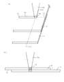
以下、上記レーザー加工装置を用いた亜鉛メッキ鋼板のレーザー溶接法について説明する。先ず、図2(a)の斜視図に示すように、下板11と上板12の重ね合わせ部上の起点P1から終点P2までの第1の直線経路K1に沿って、エネルギー密度が低く、広い照射領域19aを有した第1のレーザービーム18aを移動させながら照射する。
Hereafter, the laser welding method of the galvanized steel plate using the said laser processing apparatus is demonstrated. First, as shown in the perspective view of FIG. 2A, the energy density is low along the first linear path K1 from the starting point P1 to the ending point P2 on the overlapping portion of the
これにより、図2(b)(図1(a)のA−A線断面図)に示すように、広い照射領域19aに対応する下板11と上板12の重ね面に存在する亜鉛が第1のレーザービーム18aにより加熱されて、蒸発、脱気する。つまり、前記重ね面から発生した亜鉛蒸気は下板11と上板12の重ね合わせ部の隙間を通って外に抜ける。この時、第1のレーザービーム18aのエネルギー密度は低いので、鋼材は溶融せず、亜鉛だけが蒸発する。
As a result, as shown in FIG. 2B (a cross-sectional view taken along the line AA in FIG. 1A), the zinc present on the overlapping surface of the
その後、図3に示すように、下板11と上板12の重ね合わせ部上であって、第1の直線経路K1に隣接すると共に、第1の直線経路K1に平行な第2の直線経路K2に沿って、エネルギー密度が低く、広い照射領域19aを有した第1のレーザービーム18aを移動させながら照射する。第2の直線経路K2は、起点P3から終点P4までの直線経路であり、その経路の長さは第1の直線経路K1の長さと略同じである。この時も同様に、第2の直線経路K2に沿った広い照射領域19aに対応する下板11と上板12の重ね面に存在する亜鉛が、第1のレーザービーム18aにより加熱されて、蒸発、脱気する。
After that, as shown in FIG. 3, the second straight path on the overlapping portion of the
その後、図4に示すように、下板11と上板12の重ね合わせ部上であって、第2の直線経路K2に隣接すると共に、第2の直線経路K2に平行な第3の直線経路K3に沿って、エネルギー密度が低く、広い照射領域19aを有した第1のレーザービーム18aを移動させながら照射する。第3の直線経路K3は、起点P5から終点P6までの直線経路であり、その経路の長さは第1、第2の直線経路K1、K2の長さと略同じである。この時も同様に、第3の直線経路K3に沿った広い照射領域19aに対応する下板11と上板12の重ね面に存在する亜鉛が、第1のレーザービーム18aにより加熱されて、蒸発、脱気する。
Thereafter, as shown in FIG. 4, a third straight path on the overlapping portion of the
この場合、第1乃至第3の直線経路K1〜K3の起点P1,P3,P5は同一直線上にあり、起点P1,P3,P5も同一直線上にある。また、第1のレーザービーム18aの移動方向は左右方向のどちらでも良い。
In this case, the starting points P1, P3, and P5 of the first to third straight paths K1 to K3 are on the same straight line, and the starting points P1, P3, and P5 are also on the same straight line. Further, the moving direction of the
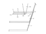
上述のようにして第1のレーザービーム18aを第1乃至第3の経路K1〜K3に沿って移動させた後に、図5(a)に示すように、第1のレーザービーム18aよりもエネルギー密度が高く、狭い照射領域19bを有した第2のレーザービーム18bを第1の直線経路K1、第3の直線経路K3に挟まれた第2の直線経路K2に沿って、好ましくは第2の直線経路K2の中心線に沿って移動させながら照射する。この時、第2のレーザービーム18bの移動方向はP3→P4、P4→P3のどちらでも良い。
After moving the
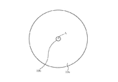
この場合、第2のレーザービーム18bの狭い照射領域19bの全部が広い照射領域19aの範囲に含まれている。広い照射領域19aと狭い照射領域19bを重ね合わせると、中心点Aを共有した同心円を形成することが好ましい。(図6を参照)このようにして、図5(b)(図5(a)のB−B線断面図)に示すように、第2の直線経路K2に沿って、狭い照射領域19bに対応する下板11と上板12の鋼板部分が溶融され、溶接接合が形成される。この時、第2の直線経路K2に対応したレーザー照射領域だけでなく、その両側の第1、第3の直線経路K1,K3に対応したレーザー照射領域も含めた広範囲においてメッキされた亜鉛が既に蒸発、脱気されているので、広範囲の亜鉛蒸気の影響を無くして良好な溶接接合を形成することができる。
In this case, the entire
つまり、第1のレーザービーム18aを1つの直線経路に沿って照射し、第2のレーザービーム18bを同じ経路に沿って照射する場合と比べると、本実施形態においては、より広範囲においてメッキされた亜鉛を蒸発、脱気した後に、溶接を行うことができるのである。これに対して、第1、第3の直線経路K1,K3の照射を行わない場合には、亜鉛の蒸発、脱気が不十分であり、ブローホールを防ぎきれない。さらに広範囲の亜鉛を除去したい場合には、直線経路の本数をさらに増やしても良い。
That is, compared with the case where the
第1乃至第3の直線経路K1〜K3の間隔はある程度自由に設定できるが、その間隔はできるだけ小さいことが好ましい。第1乃至第3の直線経路K1〜K3の間隔が大きすぎると、レーザー照射が行われない非照射領域が広くなり、亜鉛の除去効果が十分発揮されないからである。また、図3乃至5においては、第1乃至第3の直線経路K1〜K3の広い照射領域19aは離間している場合を図示したが、隣接した経路の広い照射領域19aの端部を互いにオーバーラップさせてもよい。これにより、第1乃至第3の直線経路K1〜K3の間に非照射領域が生じないようにすることができる。
The interval between the first to third linear paths K1 to K3 can be set freely to some extent, but the interval is preferably as small as possible. This is because if the distance between the first to third straight paths K1 to K3 is too large, the non-irradiation area where the laser irradiation is not performed becomes wide, and the effect of removing zinc is not sufficiently exhibited. 3 to 5 illustrate the case where the
尚、本実施形態とは異なり、第1のレーザービーム18aの照射領域を広げることで、広範囲の亜鉛を蒸発、脱気させるという手法も考えられるが、照射領域を広げただけではレーザービームのエネルギー密度の低下を招き、これを補償するためにはレーザービームの移動速度を相当小さくせざるを得ない。そうすると、生産性の低下を招く。また、ファイバーレーザー発振器17の発振出力にも限界があり、エネルギー密度を維持しながら照射領域を広げることは困難なことが多い。
Unlike the present embodiment, a method of evaporating and deaerating a wide range of zinc by expanding the irradiation area of the
また、前述のように、第1及び第2のレーザービーム18a,18bは同時移動すること無く、時間を前後して移動させているため、それらの移動速度は独立に制御することができる。これにより、溶接条件を最適化することができる。この時、第1のレーザービーム18aの移動速度は、第2のレーザービーム18bの移動速度より小さいことが好ましい。つまり、第1のレーザービーム18aの移動はゆっくり行うことにより、亜鉛の蒸発、除去を促進することができる。一方、第2のレーザービーム18bの移動はそれより速くても適度な溶接接合を形成することができ、レーザー加工時間の短縮にもつながる。
Further, as described above, the first and
これに対して、特許文献1の溶接方法にように、2つのレーザービームを同時移動させる場合には、亜鉛の除去を十分に行うためにレーザービームの移動をゆっくり行うと、鋼板部分の溶融が過剰に起こり、逆に、溶接接合の形成を最適化するためにレーザービームの移動を速く行うと、亜鉛の除去が不十分になるという欠点がある。つまり、2つのレーザービームの移動速度が同一であるために、溶接条件の最適化に制約がある。 On the other hand, when two laser beams are moved simultaneously as in the welding method of Patent Document 1, if the laser beam is moved slowly in order to sufficiently remove zinc, the steel plate portion is melted. If the laser beam is moved quickly in order to optimize the formation of the weld joint, there is a disadvantage that the removal of zinc becomes insufficient. That is, since the moving speeds of the two laser beams are the same, there is a restriction on optimization of the welding conditions.
[第2の実施形態]
第1の実施形態において、第1のレーザービーム18a及び第2のレーザービーム18bの移動する経路は直線経路であるが、それに限らず、どのような経路でもよい。本実施形態では、直線経路以外に好ましい経路として、円周経路について説明する。
尚、本実施形態においても、前記レーザー加工装置を用いるものとし、その他の条件も第1の実施形態と同様である。
[Second Embodiment]
In the first embodiment, the path of movement of the
In this embodiment, the laser processing apparatus is used, and other conditions are the same as those in the first embodiment.
先ず、図7に示すように、第1のレーザービーム18aを下板11と上板12の重ね合わせ部上の第1の円周経路K4に沿って、起点P7から出発して、再び同じ起点P7に戻るように移動させる。つまり、第1のレーザービーム18aの広い照射領域19aは第1の円周経路K4を一周することになる。これにより、第1の実施形態と同様に、広い照射領域19aに対応する下板11と上板12の重ね面に存在する亜鉛が第1のレーザービーム18aにより加熱されて、蒸発、脱気する。
First, as shown in FIG. 7, the
その後、図8に示すように、第1の円周経路K4の外側に隣接した第2の円周経路K5に沿って、第1のレーザービーム18aを起点P8から再び同じ起点P8に戻すように移動させる。つまり、第1のレーザービーム18aの照射領域19aは第2の円周経路K5を一周することになる。この時も、広い照射領域19aに対応する下板11と上板12の重ね面に存在する亜鉛が第1のレーザービーム18aにより加熱されて、蒸発、脱気する。
Thereafter, as shown in FIG. 8, along the second circumferential path K5 adjacent to the outside of the first circumferential path K4, the
その後、図9に示すように、第2の円周経路K5の外側に隣接した第3の円周経路K6に沿って、第1のレーザービーム18aを起点P9から再び同じ起点P9に戻すように移動させる。つまり、第1のレーザービーム18aの照射領域19aは第3の円周経路K6を一周することになる。この時も、広い照射領域19aに対応する下板11と上板12の重ね面に存在する亜鉛が第1のレーザービーム18aにより加熱されて、蒸発、脱気する。
Thereafter, as shown in FIG. 9, along the third circumferential path K6 adjacent to the outside of the second circumferential path K5, the
この場合、第1乃至第3の円周経路K4〜K6の中心は同じであること、つまり第1乃至第3の円周経路K4〜K6は同心円であることが好ましい。第1のレーザービーム18aを移動させる第1乃至第3の円周経路K4〜K6の順番は任意である。
In this case, the centers of the first to third circumferential paths K4 to K6 are preferably the same, that is, the first to third circumferential paths K4 to K6 are preferably concentric circles. The order of the first to third circumferential paths K4 to K6 for moving the
その後、図10に示すように、第1のレーザービーム18aよりもエネルギー密度が高く、狭い照射領域19bを有した第2のレーザービーム18bを第2の円周経路K5に沿って、好ましくは第2の円周経路K5の中心線に沿って移動させながら照射する。つまり、第2のレーザービーム18bは、第1、第3の円周経路K4、K6によって挟まれた第2の円周経路K5に沿って移動する。
Thereafter, as shown in FIG. 10, the
この場合、第2のレーザービーム18bは起点P8から出発して、再び起点P8に戻るように移動させる。つまり、第2のレーザービーム18bの照射領域19bは第2の円周経路K5を一周することになる。尚、この時の起点P8は、第1のレーザービーム18aの起点P8と一致している必要はなく、第2の円周経路K5上で任意に選ぶことができる。
In this case, the
これにより、第2の円周経路K5に沿って、狭い照射領域19bに対応する下板11と上板12の鋼板部分が溶融され、溶接接合が形成される。この時、第2の円周経路K5に対応したレーザー照射領域だけでなく、その両側の第1、第3の円周経路K4,K6に対応したレーザー照射領域も含めた広範囲においてメッキされた亜鉛が既に蒸発、脱気されているので、亜鉛蒸気の影響を無くして良好な溶接接合を形成することができる。第1乃至第3の円周経路K4〜K6の直径はある程度自由に設定できるが、円周経路の間隔は上述した理由でできるだけ小さいことが好ましい。また、さらに広範囲の亜鉛を除去したい場合には、円周経路の本数をさらに増やしても良い
このように、本実施形態によれば、レーザービームの移動経路は円周経路であり、第1の実施形態による直線経路とは異なっているが、同様の効果を得ることができる。
As a result, the steel plate portions of the
また、本実施形態によれば、第1のレーザービーム18a及び第2のレーザービーム18bを同時移動させること無く、時間を前後して移動させるので、移動経路が第1乃至第3の円周経路K4〜K6のように曲線経路の場合でも、第1のレーザービーム18a及び第2のレーザービームの移動する経路のずれを無くすことができる。これに対して、特許文献1の溶接方法にように、2つのレーザービームを同時移動させる場合には、2つの分割されたレーザービームの射出位置が異なることから、移動経路にずれを生じや易い。移動経路にずれが生じると、亜鉛が十分除去されていない鋼材部分を溶融して溶接することになるため、溶接強度の劣化等の溶接欠陥を招くという問題がある。
In addition, according to the present embodiment, the
[第3の実施形態]
本実施形態は、第1のレーザービーム18a及び第2のレーザービーム18bの移動する経路は螺旋経路である点で第1、第2の実施形態と異なっている。尚、本実施形態においても、前記レーザー加工装置を用いるものとし、その他の条件も第1の実施形態と同様である。
[Third Embodiment]
This embodiment is different from the first and second embodiments in that the path of movement of the
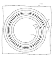
先ず、図11に示すように、第1のレーザービーム18aを下板11と上板12の重ね合わせ部上の螺旋経路K7に沿って、起点P11から出発して、終点P12まで移動させる。つまり、第1のレーザービーム18aの広い照射領域19aは螺旋経路K7上を移動することになる。この時、広い照射領域19aに対応する下板11と上板12の重ね面に存在する亜鉛が第1のレーザービーム18aにより加熱されて、蒸発、脱気する。
First, as shown in FIG. 11, the
その後、図12に示すように、第2のレーザービーム18bを下板11と上板12の重ね合わせ部上の螺旋経路K7に沿って、起点P13から出発して、終点P14まで移動させる。つまり、第2のレーザービーム18bに狭い照射領域19bは、螺旋経路K7の中でその両側の領域に第1のレーザービーム18aの照射が既に行われた経路に沿って移動する。これにより、螺旋経路K7に沿って、起点P13から終点P14に至る経路で、狭い照射領域19bに対応する下板11と上板12の鋼板部分が溶融され、溶接接合が形成される。
Thereafter, as shown in FIG. 12, the
この時、起点P13から終点P14に至る螺旋経路に対応したレーザー照射領域だけでなく、その両側の螺旋経路に対応したレーザー照射領域も含めた広範囲においてメッキされた亜鉛が既に蒸発、脱気されているので、亜鉛蒸気の影響を無くして良好な溶接接合を形成することができる。このように、本実施形態によれば、レーザービームの移動経路は螺旋経路であり、第1の実施形態による直線経路とは異なっているが、同様の効果を得ることができる。さらに広範囲の亜鉛を除去したい場合には、螺旋経路の巻き数をさらに増やしても良い。 At this time, not only the laser irradiation area corresponding to the spiral path from the starting point P13 to the end point P14, but also the zinc plated in a wide range including the laser irradiation areas corresponding to the spiral paths on both sides has already evaporated and deaerated. Therefore, the influence of zinc vapor can be eliminated and a good weld joint can be formed. Thus, according to the present embodiment, the moving path of the laser beam is a spiral path, which is different from the linear path according to the first embodiment, but the same effect can be obtained. Further, when it is desired to remove a wide range of zinc, the number of turns of the spiral path may be further increased.
また、本実施形態によれば、第1のレーザービーム18aの移動経路が螺旋状になっているので、レーザービーム照射を途中で停止させることなく、連続照射が可能になる。これにより、生産性が向上するという特有の効果も有している。
Further, according to the present embodiment, since the moving path of the
尚、上記第1乃至第3の実施形態においては、2枚の亜鉛メッキ鋼板を重ね合わせた状態でレーザー溶接を行っているが、本発明は、3枚以上の亜鉛メッキ鋼板を重ね合わせた状態でレーザー溶接を行う場合にも適用することができる。また、本発明のレーザー溶接の対象となる金属メッキ板は、亜鉛メッキ鋼板に限らず、鋼板の表面に、鋼板の融点よりも低い沸点を有した金属、例えば、アルミニウム、或いは錫をメッキしてなる金属メッキ板であってもよい。また、母材金属板の材料も鉄に限定されることはなく、例えば、鉄と他の元素との合金でもよい。 In addition, in the said 1st thru | or 3rd embodiment, although laser welding is performed in the state which piled up two galvanized steel plates, this invention is the state in which three or more galvanized steel plates were piled up. It can also be applied to laser welding. In addition, the metal plating plate to be laser welded according to the present invention is not limited to a galvanized steel plate, but a metal having a boiling point lower than the melting point of the steel plate, such as aluminum or tin, is plated on the surface of the steel plate. The metal plating board which becomes may be sufficient. Further, the material of the base metal plate is not limited to iron, and may be, for example, an alloy of iron and other elements.
以下、本発明の具体的な実施例について説明する。2枚の亜鉛メッキ鋼板(規格:GAC270 t1.2)を準備した。この亜鉛メッキ鋼板は、厚さが1.2mmであり、表面及び裏面に40g/m2の亜鉛メッキが施されたものである。そして、2枚の亜鉛メッキ鋼板の重ね合わせ部に、第1のレーザービーム18aを第1乃至第3の円周経路K4〜K6に沿って照射した。この時のファイバーレーザー発振器17の発振出力は4KWであり、第1のレーザービーム18aの広い照射領域19aは円形であり、その直径は1.0mmであった。また、第1のレーザービーム18aの移動速度は1m/分であった。(図7〜図9参照)
Hereinafter, specific examples of the present invention will be described. Two galvanized steel sheets (standard: GAC270 t1.2) were prepared. This galvanized steel sheet has a thickness of 1.2 mm, and is galvanized at 40 g / m 2 on the front and back surfaces. And the
第1のレーザービーム18aの照射後、第2のレーザービーム18bを第2の円周経路K5に沿って照射した。この時の、ファイバーレーザー発振器17の発振出力は4KWであり、第2のレーザービーム18bの狭い照射領域19bは円形であり、その直径は0.8mmであった。また、第2のレーザービーム18bの移動速度は、第1のレーザービーム18aの移動速度より速く、3.5m/分であった。(図10参照)
After the irradiation with the
ファイバーレーザー発振器17の発振出力は4KWで一定しているので、レーザービームのエネルギー密度は照射領域の面積に反比例する。第1のレーザービーム18aのエネルギー密度は、第2のレーザービーム18bのエネルギー密度の64%になる。上記の第1及び第2のレーザービーム18a,18bの照射により、2枚の亜鉛メッキ鋼板は第2の円周経路K5に沿って溶接され、その溶接強度は高く、外観も良いことが確認された。
Since the oscillation output of the
10・・・レーザー加工テーブル 11・・・下板
12・・・上板 13・・・レーザー加工ヘッド
14・・・光ファイバー 15・・・コリメーションレンズ
16・・・集光レンズ 17・・・ファイバーレーザー発振器
18・・・レーザービーム 18a・・・第1のレーザービーム
18b・・・第2のレーザービーム 19a・・・広い照射領域
19b・・・狭い照射領域
K1・・・第1の直線経路 K2・・・第2の直線経路
K3・・・第3の直線経路 K4・・・第1の円周経路
K5・・・第2の円周経路 K6・・・第3の円周経路
K7・・・螺旋経路
DESCRIPTION OF
Claims (6)
前記重ね合わせ部上の互いに隣接した第1乃至第3の経路に沿って、エネルギー密度が低く、且つ広い照射領域を有した第1のレーザービームを移動させながら照射することにより、前記広い照射領域の母材金属部分にメッキされた金属を蒸発、脱気させ、
前記第1のレーザービームを前記第1乃至第3の経路に沿って照射した後に、前記第1及び第3の経路に挟まれた前記第2の経路に沿って前記第1のレーザービームよりもエネルギー密度が高く、且つ前記第1のレーザービームよりも狭い照射領域を有した第2のレーザービームを移動させながら照射することにより、前記狭い照射領域の母材金属部分を溶融して、溶接接合させることを特徴とする金属メッキ板のレーザー溶接方法。 A metal that is welded by superimposing a plurality of metal plating plates on the surface of the base metal plate with a metal having a boiling point lower than the melting point of the base metal, and irradiating the overlap portion with a laser beam In the laser welding method for plated plates,
By irradiating while moving the first laser beam having a low energy density and a wide irradiation area along the first to third paths adjacent to each other on the overlapping portion, the wide irradiation area Evaporate and degas the metal plated on the base metal part of
After irradiating the first laser beam along the first to third paths, the first laser beam is more advanced than the first laser beam along the second path sandwiched between the first and third paths. By irradiating while moving the second laser beam having a high energy density and a narrower irradiation area than the first laser beam, the base metal part of the narrow irradiation area is melted and welded. A laser welding method for a metal plating plate, characterized by comprising:
前記重ね合わせ部上における螺旋経路に沿って、エネルギー密度が低く、且つ広い照射領域を有した第1のレーザービームを移動させながら照射することにより、前記広い照射領域の母材金属部分にメッキされた金属を蒸発させ、
前記第1のレーザービームを螺旋経路の全体に沿って照射した後に、前記螺旋経路の中でその両側の領域に前記第1のレーザービームの照射が行われた経路に沿って、前記第1のレーザービームよりもエネルギー密度が高く、且つ前記第1のレーザービームよりも狭い照射領域を有した第2のレーザービームを移動させながら照射することにより、前記狭い照射領域の母材金属部分を溶融して、溶接接合させることを特徴とする金属メッキ板のレーザー溶接方法。 A metal that is welded by superimposing a plurality of metal plating plates on the surface of the base metal plate, with a metal having a boiling point lower than the melting point of the base metal, and irradiating the overlap portion with a laser beam In the laser welding method for plated plates,
By irradiating while moving the first laser beam having a low energy density and a wide irradiation area along the spiral path on the overlapping portion, the base metal part of the wide irradiation area is plated. Evaporated metal,
After irradiating the first laser beam along the entire spiral path, the first laser beam is irradiated along the path in which the first laser beam is irradiated on both sides of the spiral path. By irradiating while moving the second laser beam having an energy density higher than that of the laser beam and having an irradiation region narrower than that of the first laser beam, the base metal portion of the narrow irradiation region is melted. And a laser welding method for a metal-plated plate, characterized by welding and joining.
Priority Applications (1)
| Application Number | Priority Date | Filing Date | Title |
|---|---|---|---|
| JP2008266687A JP5129717B2 (en) | 2008-10-15 | 2008-10-15 | Laser welding method for metal plated plate |
Applications Claiming Priority (1)
| Application Number | Priority Date | Filing Date | Title |
|---|---|---|---|
| JP2008266687A JP5129717B2 (en) | 2008-10-15 | 2008-10-15 | Laser welding method for metal plated plate |
Publications (2)
| Publication Number | Publication Date |
|---|---|
| JP2010094701A true JP2010094701A (en) | 2010-04-30 |
| JP5129717B2 JP5129717B2 (en) | 2013-01-30 |
Family
ID=42256763
Family Applications (1)
| Application Number | Title | Priority Date | Filing Date |
|---|---|---|---|
| JP2008266687A Expired - Fee Related JP5129717B2 (en) | 2008-10-15 | 2008-10-15 | Laser welding method for metal plated plate |
Country Status (1)
| Country | Link |
|---|---|
| JP (1) | JP5129717B2 (en) |
Cited By (12)
| Publication number | Priority date | Publication date | Assignee | Title |
|---|---|---|---|---|
| JP2012115876A (en) * | 2010-12-01 | 2012-06-21 | Toyota Motor Corp | Laser welding method |
| WO2012164839A1 (en) * | 2011-05-30 | 2012-12-06 | パナソニック株式会社 | Laser welding component and method for manufacturing same |
| WO2014167027A1 (en) * | 2013-04-12 | 2014-10-16 | Thales | Method for establishing a permanent bond between a ferrous alloy and an aluminium or an aluminium alloy |
| JP2015074012A (en) * | 2013-10-09 | 2015-04-20 | 日産自動車株式会社 | Method and device of laser welding of steel plate |
| JP2015077612A (en) * | 2013-10-16 | 2015-04-23 | 株式会社キーレックス | Joint assembly device and method for assembling joint assembly pipe |
| WO2015129231A1 (en) * | 2014-02-25 | 2015-09-03 | パナソニックIpマネジメント株式会社 | Laser welding method |
| WO2017047050A1 (en) * | 2015-09-15 | 2017-03-23 | パナソニックIpマネジメント株式会社 | Welded structure of metal member and welding method |
| JP2017221973A (en) * | 2016-06-09 | 2017-12-21 | 新日鐵住金株式会社 | Lap bonded joint and manufacturing method therefor |
| EP3578289A1 (en) * | 2018-06-04 | 2019-12-11 | Toyota Jidosha Kabushiki Kaisha | Laser welding method |
| KR102057551B1 (en) | 2014-09-19 | 2019-12-19 | 닛폰세이테츠 가부시키가이샤 | Laser welded joint and laser welding method |
| WO2022092042A1 (en) * | 2020-10-30 | 2022-05-05 | ファナック株式会社 | Laser welding method for workpiece |
| JP7537456B2 (en) | 2022-03-15 | 2024-08-21 | トヨタ自動車株式会社 | Welded structure manufacturing method and battery |
Families Citing this family (1)
| Publication number | Priority date | Publication date | Assignee | Title |
|---|---|---|---|---|
| DE102018102523B4 (en) * | 2018-02-05 | 2019-10-10 | Scansonic Mi Gmbh | Welding method and laser welding device for joining foil-like workpieces |
-
2008
- 2008-10-15 JP JP2008266687A patent/JP5129717B2/en not_active Expired - Fee Related
Cited By (26)
| Publication number | Priority date | Publication date | Assignee | Title |
|---|---|---|---|---|
| JP2012115876A (en) * | 2010-12-01 | 2012-06-21 | Toyota Motor Corp | Laser welding method |
| WO2012164839A1 (en) * | 2011-05-30 | 2012-12-06 | パナソニック株式会社 | Laser welding component and method for manufacturing same |
| JP5457605B2 (en) * | 2011-05-30 | 2014-04-02 | パナソニック株式会社 | Laser-joined component and manufacturing method thereof |
| WO2014167027A1 (en) * | 2013-04-12 | 2014-10-16 | Thales | Method for establishing a permanent bond between a ferrous alloy and an aluminium or an aluminium alloy |
| US9908194B2 (en) | 2013-04-12 | 2018-03-06 | Thales | Method for establishing a permanent bond between a ferrous alloy and an aluminium or an aluminium alloy |
| JP2016522748A (en) * | 2013-04-12 | 2016-08-04 | タレス | Method for establishing a permanent bond between an iron alloy and aluminum or an aluminum alloy |
| JP2015074012A (en) * | 2013-10-09 | 2015-04-20 | 日産自動車株式会社 | Method and device of laser welding of steel plate |
| JP2015077612A (en) * | 2013-10-16 | 2015-04-23 | 株式会社キーレックス | Joint assembly device and method for assembling joint assembly pipe |
| CN106029291B (en) * | 2014-02-25 | 2018-05-04 | 松下知识产权经营株式会社 | Method for laser welding |
| EP3112077A4 (en) * | 2014-02-25 | 2017-02-22 | Panasonic Intellectual Property Management Co., Ltd. | Laser welding method |
| JPWO2015129231A1 (en) * | 2014-02-25 | 2017-03-30 | パナソニックIpマネジメント株式会社 | Laser welding method |
| CN106029291A (en) * | 2014-02-25 | 2016-10-12 | 松下知识产权经营株式会社 | Laser welding method |
| WO2015129231A1 (en) * | 2014-02-25 | 2015-09-03 | パナソニックIpマネジメント株式会社 | Laser welding method |
| US10286491B2 (en) | 2014-02-25 | 2019-05-14 | Panasonic Intellectual Property Management Co., Ltd. | Laser welding method |
| KR102057551B1 (en) | 2014-09-19 | 2019-12-19 | 닛폰세이테츠 가부시키가이샤 | Laser welded joint and laser welding method |
| WO2017047050A1 (en) * | 2015-09-15 | 2017-03-23 | パナソニックIpマネジメント株式会社 | Welded structure of metal member and welding method |
| CN107949454A (en) * | 2015-09-15 | 2018-04-20 | 松下知识产权经营株式会社 | The welding structure and welding method of hardware |
| JPWO2017047050A1 (en) * | 2015-09-15 | 2018-06-14 | パナソニックIpマネジメント株式会社 | Welded structure of metal member and welding method |
| US11428251B2 (en) | 2015-09-15 | 2022-08-30 | Panasonic Intellectual Property Management Co., Ltd. | Weld structure of metal member and welding process |
| JP2020089919A (en) * | 2015-09-15 | 2020-06-11 | パナソニックIpマネジメント株式会社 | Metal member weld structure and welding method |
| JP2017221973A (en) * | 2016-06-09 | 2017-12-21 | 新日鐵住金株式会社 | Lap bonded joint and manufacturing method therefor |
| JP2019209349A (en) * | 2018-06-04 | 2019-12-12 | トヨタ自動車株式会社 | Laser welding method |
| EP3578289A1 (en) * | 2018-06-04 | 2019-12-11 | Toyota Jidosha Kabushiki Kaisha | Laser welding method |
| US11511371B2 (en) | 2018-06-04 | 2022-11-29 | Toyota Jtdosha Kabushiki Kaisha | Laser welding method |
| WO2022092042A1 (en) * | 2020-10-30 | 2022-05-05 | ファナック株式会社 | Laser welding method for workpiece |
| JP7537456B2 (en) | 2022-03-15 | 2024-08-21 | トヨタ自動車株式会社 | Welded structure manufacturing method and battery |
Also Published As
| Publication number | Publication date |
|---|---|
| JP5129717B2 (en) | 2013-01-30 |
Similar Documents
| Publication | Publication Date | Title |
|---|---|---|
| JP5129717B2 (en) | Laser welding method for metal plated plate | |
| JP4612076B2 (en) | Laser welding method for metal plated plate | |
| JP5024475B1 (en) | Laser welded steel pipe manufacturing method | |
| JP6554670B2 (en) | Laser welding method | |
| JP6846619B2 (en) | Laser welding method | |
| JP5531623B2 (en) | Laser lap welding method of galvanized steel sheet | |
| WO2010005025A1 (en) | Laser lap welding method for galvanized steel sheets | |
| WO2013001934A1 (en) | Hybrid welding method for t-joint using laser beam welding and arc welding | |
| JP2009148781A (en) | Laser welding method | |
| JPH0732180A (en) | Laser beam welding method for galvanized steel sheets | |
| JP5866790B2 (en) | Laser welded steel pipe manufacturing method | |
| JP4797659B2 (en) | Laser welding method | |
| JP4620753B2 (en) | Laser welding method for metal plated plate | |
| JP3596326B2 (en) | Welding method of aluminum alloy | |
| JP2010094702A (en) | Method of laser welding metal plated plate | |
| JP4915315B2 (en) | Laser welding method and laser welding apparatus | |
| JP2005144504A (en) | Lap laser welding method for galvanized steel sheet and welded joint of lap welded galvanized steel sheet | |
| JP2007253181A (en) | Laser beam welding method | |
| JP2011115836A (en) | Method of laser welding metal plated plate | |
| JP5803160B2 (en) | Laser welded steel pipe manufacturing method | |
| JP2011156572A (en) | Laser welding method | |
| JP2012228716A (en) | Laser welding apparatus and laser welding method | |
| JP5312060B2 (en) | Laser welding method | |
| KR20140077267A (en) | Method of laser welding | |
| JP5724294B2 (en) | Laser welded steel pipe manufacturing method |
Legal Events
| Date | Code | Title | Description |
|---|---|---|---|
| A621 | Written request for application examination |
Free format text: JAPANESE INTERMEDIATE CODE: A621 Effective date: 20110705 |
|
| A977 | Report on retrieval |
Free format text: JAPANESE INTERMEDIATE CODE: A971007 Effective date: 20121019 |
|
| TRDD | Decision of grant or rejection written | ||
| A01 | Written decision to grant a patent or to grant a registration (utility model) |
Free format text: JAPANESE INTERMEDIATE CODE: A01 Effective date: 20121029 |
|
| A01 | Written decision to grant a patent or to grant a registration (utility model) |
Free format text: JAPANESE INTERMEDIATE CODE: A01 |
|
| A61 | First payment of annual fees (during grant procedure) |
Free format text: JAPANESE INTERMEDIATE CODE: A61 Effective date: 20121102 |
|
| R150 | Certificate of patent or registration of utility model |
Free format text: JAPANESE INTERMEDIATE CODE: R150 Ref document number: 5129717 Country of ref document: JP Free format text: JAPANESE INTERMEDIATE CODE: R150 |
|
| FPAY | Renewal fee payment (event date is renewal date of database) |
Free format text: PAYMENT UNTIL: 20151109 Year of fee payment: 3 |
|
| R250 | Receipt of annual fees |
Free format text: JAPANESE INTERMEDIATE CODE: R250 |
|
| R250 | Receipt of annual fees |
Free format text: JAPANESE INTERMEDIATE CODE: R250 |
|
| R250 | Receipt of annual fees |
Free format text: JAPANESE INTERMEDIATE CODE: R250 |
|
| R250 | Receipt of annual fees |
Free format text: JAPANESE INTERMEDIATE CODE: R250 |
|
| R250 | Receipt of annual fees |
Free format text: JAPANESE INTERMEDIATE CODE: R250 |
|
| R250 | Receipt of annual fees |
Free format text: JAPANESE INTERMEDIATE CODE: R250 |
|
| LAPS | Cancellation because of no payment of annual fees |