JP2010094611A - Rotation type solid-liquid separation apparatus - Google Patents
Rotation type solid-liquid separation apparatus Download PDFInfo
- Publication number
- JP2010094611A JP2010094611A JP2008268223A JP2008268223A JP2010094611A JP 2010094611 A JP2010094611 A JP 2010094611A JP 2008268223 A JP2008268223 A JP 2008268223A JP 2008268223 A JP2008268223 A JP 2008268223A JP 2010094611 A JP2010094611 A JP 2010094611A
- Authority
- JP
- Japan
- Prior art keywords
- rotary
- liquid
- solid
- liquid separator
- separated
- Prior art date
- Legal status (The legal status is an assumption and is not a legal conclusion. Google has not performed a legal analysis and makes no representation as to the accuracy of the status listed.)
- Granted
Links
Images


Classifications
-
- F—MECHANICAL ENGINEERING; LIGHTING; HEATING; WEAPONS; BLASTING
- F16—ENGINEERING ELEMENTS AND UNITS; GENERAL MEASURES FOR PRODUCING AND MAINTAINING EFFECTIVE FUNCTIONING OF MACHINES OR INSTALLATIONS; THERMAL INSULATION IN GENERAL
- F16C—SHAFTS; FLEXIBLE SHAFTS; ELEMENTS OR CRANKSHAFT MECHANISMS; ROTARY BODIES OTHER THAN GEARING ELEMENTS; BEARINGS
- F16C35/00—Rigid support of bearing units; Housings, e.g. caps, covers
- F16C35/04—Rigid support of bearing units; Housings, e.g. caps, covers in the case of ball or roller bearings
- F16C35/042—Housings for rolling element bearings for rotary movement
- F16C35/047—Housings for rolling element bearings for rotary movement with a base plate substantially parallel to the axis of rotation, e.g. horizontally mounted pillow blocks
-
- F—MECHANICAL ENGINEERING; LIGHTING; HEATING; WEAPONS; BLASTING
- F16—ENGINEERING ELEMENTS AND UNITS; GENERAL MEASURES FOR PRODUCING AND MAINTAINING EFFECTIVE FUNCTIONING OF MACHINES OR INSTALLATIONS; THERMAL INSULATION IN GENERAL
- F16C—SHAFTS; FLEXIBLE SHAFTS; ELEMENTS OR CRANKSHAFT MECHANISMS; ROTARY BODIES OTHER THAN GEARING ELEMENTS; BEARINGS
- F16C19/00—Bearings with rolling contact, for exclusively rotary movement
- F16C19/22—Bearings with rolling contact, for exclusively rotary movement with bearing rollers essentially of the same size in one or more circular rows, e.g. needle bearings
- F16C19/34—Bearings with rolling contact, for exclusively rotary movement with bearing rollers essentially of the same size in one or more circular rows, e.g. needle bearings for both radial and axial load
- F16C19/38—Bearings with rolling contact, for exclusively rotary movement with bearing rollers essentially of the same size in one or more circular rows, e.g. needle bearings for both radial and axial load with two or more rows of rollers
-
- F—MECHANICAL ENGINEERING; LIGHTING; HEATING; WEAPONS; BLASTING
- F16—ENGINEERING ELEMENTS AND UNITS; GENERAL MEASURES FOR PRODUCING AND MAINTAINING EFFECTIVE FUNCTIONING OF MACHINES OR INSTALLATIONS; THERMAL INSULATION IN GENERAL
- F16C—SHAFTS; FLEXIBLE SHAFTS; ELEMENTS OR CRANKSHAFT MECHANISMS; ROTARY BODIES OTHER THAN GEARING ELEMENTS; BEARINGS
- F16C23/00—Bearings for exclusively rotary movement adjustable for aligning or positioning
- F16C23/06—Ball or roller bearings
- F16C23/08—Ball or roller bearings self-adjusting
- F16C23/082—Ball or roller bearings self-adjusting by means of at least one substantially spherical surface
- F16C23/086—Ball or roller bearings self-adjusting by means of at least one substantially spherical surface forming a track for rolling elements
Abstract
Description
この発明は、回転駆動により原液を分離物と分離液に分離する回転式固液分離装置に関するものである。 The present invention relates to a rotary solid-liquid separation device that separates a stock solution into a separated product and a separated solution by rotational driving.
従来の回転式固液分離装置の一つに、遠心力を利用して原液を固体分と液体分とに分離するスクリュウデカンタ型遠心分離機がある(例えば、特許文献1参照)。
この遠心分離機は、高速で回転する外胴ボウルと、この外胴ボウル内に配置されて該外胴ボウルと同一方向に回転する内胴スクリュウと、前記外胴ボウルと前記内胴スクリュウとに回転差を与えるギアボックスと、前記外胴ボウルおよび前記内胴スクリュウの回転支軸を支持する軸受(回転支持器)とを備えた概要構造となっている。
One conventional rotary solid-liquid separator is a screw decanter type centrifuge that separates a stock solution into a solid component and a liquid component using centrifugal force (see, for example, Patent Document 1).
The centrifuge includes an outer body bowl that rotates at a high speed, an inner body screw that is disposed in the outer body bowl and rotates in the same direction as the outer body bowl, and the outer body bowl and the inner body screw. It has a general structure including a gear box that gives a rotation difference, and a bearing (rotation supporter) that supports the rotation spindle of the outer shell bowl and the inner shell screw.
このような遠心分離機では、内胴スクリュウの内部に供給された原液が内胴スクリュウの遠心力により外胴ボウル内(詳しくは、内胴スクリュウと外胴ボウルとの間)に流入して遠心力の作用で固液分離され、汚泥等の分離物(固体分)は、内胴スクリュウの回転により移送・圧密されて外胴ボウルの小径側から系外に排出される。一方、分離液(液体分)は内胴スクリュウの羽根間を螺旋状に回転しながら外胴ボウルの大径側から系外に排出される。 In such a centrifuge, the undiluted solution supplied into the inner cylinder screw flows into the outer cylinder bowl (specifically, between the inner cylinder screw and the outer cylinder bowl) by the centrifugal force of the inner cylinder screw and is centrifuged. Solid-liquid separation is performed by the action of the force, and the separated matter (solid matter) such as sludge is transferred and consolidated by the rotation of the inner cylinder screw, and is discharged out of the system from the small diameter side of the outer cylinder bowl. On the other hand, the separated liquid (liquid component) is discharged out of the system from the large-diameter side of the outer cylinder bowl while spirally rotating between the blades of the inner cylinder screw.
また、この種の回転式固液分離機において、回転支軸を支持する回転支持器は、メンテナンスなどの際に分割できない一体構造のハウジングボックスを適用し、該ハウジングボックスの内部にベアリングを組み込んで回転機器の回転支軸を支持している。 Also, in this type of rotary solid-liquid separator, the rotary supporter that supports the rotary spindle uses a single-piece housing box that cannot be divided during maintenance, etc., and incorporates a bearing inside the housing box. Supports the rotating spindle of rotating equipment.
このような回転支持器では、分割できない一体構造のハウジングボックスの内部に組み込まれたベアリングや回転支軸の状況を点検・確認することができないため、回転機器の維持管理上、好ましくないという課題があった。特に、回転機器の定期点検やベアリング等の部品交換を行う際には、回転機器のみならず、ハウジングボックスも分解したり取り外したりしなければならないという課題があった。 In such a rotary supporter, since it is impossible to check and confirm the status of the bearing and the rotary support shaft incorporated in the housing box having an integral structure that cannot be divided, there is a problem that it is not preferable in the maintenance management of the rotating equipment. there were. In particular, when performing periodic inspection of rotating equipment and replacement of parts such as bearings, there is a problem that not only the rotating equipment but also the housing box must be disassembled and removed.
そこで、工作機械の分野では、支軸頭のハウジングを前部ハウジングと後部ハウジングに分割し、前部ハウジングと前部軸受部、支軸および後部軸受部とを一体的に組み付けた前部ハウジングユニットを構成し、この前部ハウジングユニットを後部ハウジングとの間で着脱可能に締結した工作機械の支軸装置が提供されている(例えば、特許文献2参照)。 Therefore, in the field of machine tools, a front housing unit in which the housing of the spindle head is divided into a front housing and a rear housing, and the front housing, the front bearing portion, the support shaft and the rear bearing portion are assembled together. And a spindle device for a machine tool in which the front housing unit is detachably fastened to the rear housing (see, for example, Patent Document 2).
このような特許文献1の工作機械の支軸装置によれば、前部ハウジングユニットを後部ハウジングから軸方向に抜き出すことによって、前部ハウジングユニットごと前部軸受部、支軸及び後部軸受部を交換できるというものである。
According to the spindle device of the machine tool disclosed in
特許文献1の遠心分離機やその他の遠心ろ過濃縮機等の回転式固液分離機においては、固液分離する原液が生物学的排水処理や廃棄物処理に起因して発生する汚泥等の場合、排出された分離物である濃縮汚泥や脱水汚泥から、また分離液である濃縮分離液や脱水分離液から腐食性ガスが発生し、この腐食性ガスが配管を介して回転式固液分離機内や回転支持器内に流入し、各種の機器や構成部材を腐食(主に錆を発生)させてしまうという課題があった。
In rotary solid-liquid separators such as the centrifugal separator of
また、食品工場などでは原液、分離物、分離液が長期貯留により腐敗して腐食性ガスを発生させることもあり、さらに化学工場などでは原液そのものが劇毒物であり腐食性ガスを発生させることもある。 In addition, undiluted solutions, separated products, and separated solutions may decay due to long-term storage in food factories and the like, and corrosive gases may be generated. is there.
通常、回転式固液分離機から排出された分離物(濃縮汚泥や脱水汚泥など)や分離液(濃縮分離液や脱水分離液など)は、一旦貯留槽に貯留され、その後系外に排出されるが、貯留している際に、腐食性の硫化水素ガス等が発生する。通常の汚泥処理設備においては、脱臭設備が設置されており、貯留槽にも脱臭設備からのガス吸引管が接続され、貯留槽内のガスは吸引され脱臭される。しかしながら、建設(設備)コストや運転コストの兼ね合いから、十分な換気能力を備えていないケースが多く、さらに悪臭防止のために貯留槽の密閉性を高くすると、腐食性ガスは行き場がなくなり、回転式固液分離機に通じる配管を介して移流し、回転式固液分離機内に流れ込む(逆流する)ことになる。 Usually, the separation (concentrated sludge, dewatered sludge, etc.) and separation liquid (concentrated sludge, dehydrated sludge, etc.) discharged from the rotary solid-liquid separator are once stored in a storage tank and then discharged outside the system. However, corrosive hydrogen sulfide gas is generated during storage. In a normal sludge treatment facility, a deodorization facility is installed, a gas suction pipe from the deodorization facility is connected to the storage tank, and the gas in the storage tank is sucked and deodorized. However, because of the balance between construction (equipment) costs and operation costs, there are many cases where sufficient ventilation capacity is not provided. Further, if the storage tank is made tighter to prevent bad odors, the corrosive gas has no place to go and rotates. The liquid is transferred through a pipe that leads to the solid-liquid separator and flows into the rotary solid-liquid separator (backflow).
このような課題に対して、別途貯留槽に換気設備を設けることも考えられるが、この場合、相応の能力の設備が必要であるため、機器費用や設置費用が新たに発生し、また定期的な維持管理や保守管理も必要であり、電気代など運転コストもかかる。 In order to deal with such problems, it may be possible to install a ventilation system in the separate storage tank. However, in this case, equipment with appropriate capacity is required. Maintenance and management are also necessary, and there is an operating cost such as electricity bill.
前述のように回転式固液分離機内に流れ込んだ腐食性ガスは、回転式固液分離機の機器や構成部材を腐食させ、さらに回転支持器内にも侵入して、回転支持器内のベアリングなど構成部材も腐食させてしまう。
とくに、回転支軸が高速回転する遠心分離機や遠心ろ過濃縮機では、回転支持器の構成機器や部材が腐食すれば、運転や機能の発揮に重大な支障をきたし、とくに回転支持器が腐食により機能しなければ本体の破損や破壊など重大な事故が発生する危険がある。
As described above, the corrosive gas that has flowed into the rotary solid-liquid separator corrodes the rotary solid-liquid separator equipment and components, and further penetrates into the rotary supporter. The components are also corroded.
In particular, in centrifugal separators and centrifugal filtration concentrators whose rotating spindles rotate at high speeds, if the components and parts of the rotating supporter corrode, it will cause a serious hindrance to the operation and performance of the rotating supporter. Otherwise, there is a risk of serious accidents such as damage or destruction of the main unit.
ところで、腐食性ガスは、速やかに発生し、移流するわけではなく、回転式固液分離機の運転が終了し停止している間(例えば夜間)に徐々に発生して移流してくるため、遠心分離機内では回転(運転)時に比べ空気の交換がほとんどなく、侵入してきた腐食性ガスが滞留することにより、前述のように各種の機器や構成部材の腐食を進めてしまう。 By the way, corrosive gas is not generated and transferred quickly, but gradually generated and transferred while the operation of the rotary solid-liquid separator is stopped and stopped (for example, at night) In the centrifuge, there is almost no exchange of air as compared with the time of rotation (operation), and the corrosive gas that has infiltrated stays, and as a result, the various devices and components are corroded as described above.
さらに、回転式固液分離機、例えば遠心分離機が複数台(予備用を含む)設けられた汚泥処理施設では、すべての遠心分離機を同時に稼動させることはなく、交互運転(稼動)させる。このような場合、稼動していない(休止している)遠心分離機では、接続する分離物や分離液の排出管が空になっていて、これらの管を介して稼動している遠心分離機から排出される腐食性ガスや貯留槽から逆流してくる腐食性ガスが侵入しやすく、稼動していないため空気の入れ替え等がほとんどないこともあり、確実に前記腐食が進行してしまう。 Furthermore, in a sludge treatment facility provided with a plurality of rotary solid-liquid separators, for example, centrifuges (including a spare), all the centrifuges are not operated simultaneously but are operated alternately (operated). In such a case, in a centrifuge that is not in operation (rested), the connected separation product and separation liquid discharge pipes are emptied, and the centrifuge operates through these pipes. The corrosive gas discharged from the tank or the corrosive gas flowing back from the storage tank easily enters, and since it is not in operation, there is almost no exchange of air, and the corrosion proceeds reliably.
また遠心分離機は、騒音防止や作業環境向上などを目的に、(遠心分離機や付属設備を密閉性の高い一つの容器内に納めた)パッケージ型とするケースが多々ある。そのような場合、遠心分離機内に侵入した腐食性ガスは、パッケージ内に滞留して、より一層遠心分離機や回転支持器はもちろんのこと、操作盤などの関連機器さえも腐食させてしまう。 In many cases, the centrifuge is of a package type (with the centrifuge and attached equipment housed in a single sealed container) for the purpose of preventing noise and improving the working environment. In such a case, the corrosive gas that has entered the centrifuge stays in the package and further corrodes related equipment such as the operation panel as well as the centrifuge and the rotary supporter.
回転式固液分離機とくに遠心分離機において、本体や回転支持器の機器や構成部材が腐食すると、下記の問題が発生する。
(1)ベアリングや回転支軸の腐食により異常音や異常振動が発生し、運転や機能の発揮に支障をきたし、また故障の原因となる。
(2)遠心分離機の高速回転時の異常振動等が続くと、破損や破壊など重大事故が発生する危険がある。
(3)遠心分離機の耐用年数を短縮(経年劣化を加速)させてしまう。
(4)孔食(ステンレスの表面腐食)等を起点に、回転体に亀裂(クラック)を発生させて重大事故になることもある。
(5)硫化水素ガスにより機器内部の水滴を硫酸(強酸性)化し、内胴スクリュウ羽根の先端に取り付けた耐摩耗材を剥離させてしまい、固液分離性能に支障を来す。
(6)故障や劣化により、機器保全や修理修繕に高額な費用を要することになり、修理期間中は運転(処理)することができず、所有者の負担を一層増大させる。
(7)重大事故になれば、装置の交換、各種被害の復旧や弁済が必要となる。
In rotary solid-liquid separators, especially centrifuges, the following problems occur when the equipment and components of the main body and rotary supporter are corroded.
(1) Abnormal noise and vibration are generated due to corrosion of bearings and rotating spindles, which impairs operation and function, and causes failure.
(2) If abnormal vibration during high-speed rotation of the centrifuge continues, there is a risk of serious accidents such as breakage or destruction.
(3) The service life of the centrifuge is shortened (accelerating aging degradation).
(4) Starting from pitting corrosion (surface corrosion of stainless steel) or the like, a crack may occur in the rotating body, resulting in a serious accident.
(5) Hydrogen sulfide gas makes the water droplets inside the equipment sulfuric acid (strongly acidic), causing the wear-resistant material attached to the tip of the inner cylinder screw blades to peel off, impairing the solid-liquid separation performance.
(6) Due to failure or deterioration, equipment maintenance and repair and repair are expensive, and cannot be operated (processed) during the repair period, further increasing the burden on the owner.
(7) If a serious accident occurs, it will be necessary to replace the equipment, recover from various damages, and repay.
また、前記の回転式固液分離機では、この内部に供給された原液を、回転駆動力を用いて分離物と分離液とに固液分離するが、回転支軸が確実に支持され、また管理されていないと、摩耗や運転コストの上昇(エネルギー効率の悪化)を招く。 In the rotary solid-liquid separator, the stock solution supplied inside is separated into a separated liquid and a separated liquid using a rotational driving force, but the rotating support shaft is securely supported, and If not managed, it will lead to wear and increased operating costs (deteriorating energy efficiency).
とくに、回転支軸が高速回転する遠心分離機や遠心ろ過濃縮機では、本体に供給された原液に大きな重力加速度を与えて原液を固液分離するため、回転支軸が適切な振動値、温度に維持されるように確実に支持され、管理されていないと、摩耗や運転コストの上昇(エネルギー効率の悪化)を招くばかりか、偏心による破壊などの重大事故につながる。
また、遠心分離機や遠心ろ過濃縮機の効率的で安定した運転や故障・破壊の防止のため、遠心分離機本体について、分解等を伴う定期点検や部品交換等の維持管理業務を実施する必要があるが、それには精密で厳格な技術や作業が要求される。
とくに横型遠心分離機は、高速で回転し、1000G〜4000Gという高い遠心効果を発生する機械であるため、しっかりとした運転管理や維持管理を行わなければならない。例えば、機器本体の振動が増幅する場合には、回転の偏心や回転軸の摩耗などが考えられ、速やかに対応しなければならない。しかしながら、回転数によって信号限界値が異なるなど、製造者や専門の者でなければ把握し得ない異常(危険)な兆候もあるため、常に厳しい運転管理や保守点検が必要であることは当然として、精密な点検を定期的に実施しなければならない。
In particular, in centrifugal separators and centrifugal filtration concentrators where the rotating spindle rotates at high speed, the rotating spindle has an appropriate vibration value and temperature to give a large gravitational acceleration to the undiluted solution supplied to the main unit and separate the undiluted solution. If not securely supported and managed so as to be maintained at the same time, not only will wear and operating costs increase (decrease in energy efficiency), but it will also lead to serious accidents such as destruction due to eccentricity.
In addition, in order to efficiently and stably operate the centrifuge and centrifugal filtration concentrator, and to prevent breakdown and destruction, it is necessary to carry out maintenance and management operations such as periodic inspections involving disassembly and replacement of parts of the centrifuge body. However, it requires precise and strict technology and work.
In particular, a horizontal centrifuge is a machine that rotates at a high speed and generates a high centrifugal effect of 1000 G to 4000 G, and therefore must be firmly operated and maintained. For example, when the vibration of the device main body is amplified, the eccentricity of the rotation, the wear of the rotating shaft, etc. can be considered, and it must be dealt with promptly. However, since there are abnormal signs (dangerous) that can only be grasped by manufacturers and specialists such as signal limit values depending on the number of revolutions, it is natural that strict operation management and maintenance inspections are always necessary. A precise inspection must be carried out regularly.
しかるに、回転式固液分離機の回転支軸を支持する一般的な回転支持器では、回転支軸のベアリングを覆うハウジング分解できない構造となっているため、該ハウジングに収納されたベアリングや回転支軸の状況を点検・確認することができず、回転機器の維持管理上、好ましくないという課題があった。 However, a general rotary supporter that supports the rotary spindle of the rotary solid-liquid separator has a structure in which the housing that covers the bearing of the rotary spindle cannot be disassembled. The situation of the shaft could not be inspected / confirmed, and there was a problem that it was not preferable for the maintenance of the rotating equipment.
そこで、前記ハウジングを前後に分解可能な構造とした回転支持器(特許文献2の工作機械の支軸装置)も提供されているが、この場合でも、前記ハウジング内に収納されたベアリングや回転支軸の状況を容易に点検・確認することが難しかった。 Therefore, a rotary supporter (a spindle device for a machine tool of Patent Document 2) having a structure in which the housing can be disassembled back and forth is also provided. Even in this case, a bearing and a rotary support housed in the housing are also provided. It was difficult to easily check and confirm the shaft status.
すなわち、特許文献2の工作機械の支軸装置においても、メンテナンスに際して前部ハウジングユニット内部の軸受や支軸の状況を点検・確認することができないという課題がある。また、前部ハウジングユニット内部の部品交換に際しては、特殊で大がかりな支軸交換冶具を所定の箇所に設置し、該支軸交換冶具により前部ハウジングユニットを後部ハウジングから軸方向に抜き出して前部ハウジングユニットごと新たなものと取り替えなければならず、新たな前部ハウジングユニットの組み付けも非常に煩雑化しており、精密で厳格な技術や作業が要求される回転機器において、分解等を伴う定期点検や部品交換等の維持管理業務を速やかに効率よく実施するという点での難点が多く、さらには特殊で大がかりな支軸交換冶具は設備費も嵩む等の課題がある。
That is, the spindle device of the machine tool of
とくに、回転支軸が高速回転する遠心分離機や遠心ろ過濃縮機の点検や部品交換(法規制で手法や頻度が厳密に規定:労働安全衛生法第141条等)では、高速で回転して大きな重力加速度を発生させる重機械であるため、わずかな歪み、芯振れ、アンバランス、水準の傾き、規定以上の誤差等により、本体、回転支持器、ベアリング等を破損・破壊してしまう可能性があった。 In particular, check and replacement of centrifuges and centrifugal filtration concentrators whose rotating spindles rotate at high speed (methods and frequencies are strictly defined by laws and regulations: Article 141 of the Industrial Safety and Health Act, etc.) Because it is a heavy machine that generates a large gravitational acceleration, the main unit, rotating support, bearings, etc. may be damaged or destroyed by slight distortion, runout, unbalance, level inclination, or error more than specified. was there.
そのため、遠心分離機や遠心ろ過濃縮機は精密機械として取り扱う必要があるばかりか、本体のみならず、ハウジングも分解したり取り外したりすると、その都度、慎重且つ精密な設置・据付を行わなければ成らず、高度な技術や長年の経験を持つ熟練した技術者が必要で、煩雑な作業が伴う。そのため、点検が完了するまで長い期間や多くの人手が必要となり、費用が高額になってしまう。
さらには、点検中でも通常の運転、処理を行わなければならず、そのため、代替装置の設置や予め余裕を持った設備の構築、また、これに要する広い敷地の確保など、建設コストの上昇を招いていた。
For this reason, it is necessary to handle centrifuges and centrifugal filtration concentrators as precision machines, and not only the main unit but also the housing must be disassembled and removed without careful and precise installation and installation each time. First, skilled engineers with advanced technology and many years of experience are required, which is complicated. For this reason, a long period of time and a lot of manpower are required until the inspection is completed, and the cost becomes high.
In addition, normal operation and processing must be performed even during inspection, which leads to an increase in construction costs such as the installation of alternative equipment, the construction of sufficient facilities, and the securing of a large site required for this. It was.
また、回転式固液分離装置では、回転支軸を安定して効率よく稼動させるためには、回転支持器のベアリングを良好な状態に維持し、損傷や破壊を防がなければならない。
とくに、高速で回転して大きな重力加速度を発生させる遠心分離機をより安定して効率よく稼動させるには、ベアリングを良好な状態に維持し、損傷や破壊を防がなければならず、良質で良好な(異物の混入がなく、適切な温度、粘性、量の)潤滑油を適正に供給することが重要である。
Further, in the rotary solid-liquid separator, in order to operate the rotary spindle stably and efficiently, the bearing of the rotary supporter must be maintained in a good state to prevent damage or destruction.
In particular, in order to operate a centrifuge that rotates at a high speed and generates a large gravitational acceleration more stably and efficiently, the bearings must be kept in good condition to prevent damage and destruction. It is important to properly supply a good lubricating oil (with no foreign matter mixed, at an appropriate temperature, viscosity and quantity).
ベアリングへの良好な潤滑油の供給が適切かつ効率的に行われないと、当然ながら分解しての点検や修理修繕の頻度が増え、上記課題が頻繁に発生し、遠心分離機等の運転に支障を来すと共に、所有者の負担を増大させてしまう。
回転支軸の安定した滑らかな回転およびベアリングの機能発揮のため、ハウジング内へ潤滑油を十分に供給する必要があるが、ベアリングを覆うハウジングが確実にシールされていないと、潤滑油が外部へ漏れ出し(飛散し)、周辺を汚損させるだけでなく、潤滑油を浪費しランニングコストの上昇を招く。もちろん、潤滑油が不足することにもつながり、回転支軸の安定した滑らかな回転やベアリングの機能発揮を阻害し、遠心分離機等の故障(ベアリングの焼き付き)を誘発することになる。
If the supply of good lubricating oil to the bearings is not performed properly and efficiently, the frequency of inspections and repairs will increase as a matter of course, and the above problems will frequently occur, resulting in the operation of centrifuges, etc. This causes trouble and increases the burden on the owner.
In order to achieve stable and smooth rotation of the rotation support shaft and the function of the bearing, it is necessary to supply enough lubricating oil into the housing. However, if the housing covering the bearing is not securely sealed, the lubricating oil will be discharged to the outside. In addition to leaking (scattering) and fouling the surroundings, the lubricating oil is wasted and the running cost is increased. Of course, this leads to a shortage of lubricating oil, which inhibits the stable and smooth rotation of the rotating spindle and the function of the bearing, and induces a failure of the centrifuge (bearing seizure).
この発明は、上述のような課題を解決するためになされたもので、腐食性ガスの侵入に起因した諸々の不都合を解消することが可能で、かつ、回転支軸の円滑な回転を確保できるとともに、固液分離機の定期点検や部品交換を容易に手際よく実施することができる回転式固液分離装置を提供することを目的とする。 The present invention has been made to solve the above-described problems, and can solve various inconveniences caused by the invasion of corrosive gas, and can ensure smooth rotation of the rotating support shaft. At the same time, an object is to provide a rotary solid-liquid separator capable of easily and skillfully carrying out periodic inspection and replacement of parts of a solid-liquid separator.
この発明に係る回転式固液分離装置は、原液を分離物と分離液に分離する回転式固液分離機と、該回転式固液分離機の回転軸を支持する回転支持器と、ガスの流入を防止するガス流入防止器とからなることを特徴とする。 A rotary solid-liquid separation device according to the present invention includes a rotary solid-liquid separator that separates a raw liquid into a separated product and a separated liquid, a rotary support that supports a rotary shaft of the rotary solid-liquid separator, and a gas It comprises a gas inflow preventer that prevents inflow.
この発明に係る回転式固液分離装置の前記回転支持器は、基部ハウジング、上部ハウジング、ベアリングおよび潤滑油供給部材を備えていることを特徴とする。 The rotary supporter of the rotary solid-liquid separator according to the present invention includes a base housing, an upper housing, a bearing, and a lubricating oil supply member.
この発明に係る回転式固液分離装置のガス流入防止器は、前記回転式固液分離機に接続する配管に設けられた開閉弁であることを特徴とする。 The gas inflow preventer of the rotary solid-liquid separator according to the present invention is an on-off valve provided in a pipe connected to the rotary solid-liquid separator.
この発明に係る回転式固液分離装置の回転式固液分離機は、外胴ボウル、内胴スクリュウ、ギアボックスおよび駆動機を備えた遠心分離機であることを特徴とする。 The rotary solid-liquid separator of the rotary solid-liquid separator according to the present invention is a centrifuge having an outer trunk bowl, an inner trunk screw, a gear box, and a drive unit.
この発明の回転式固液分離装置によれば、次のような幾多の効果が得られる。
(1)回転式固液分離機の回転支軸(回転軸)を確実に支持すると共に、滑らかで効率的な回転支軸の回転を確保できる。とくに、回転式固液分離機として回転支軸が高速回転する遠心分離機や遠心ろ過濃縮機を用いた場合、回転支軸の振動や温度を適正に維持でき、また、ベアリングを良好な状態に維持して回転体の損傷や破壊を防ぐことができ、偏心による破壊などの重大事故を未然に防ぐことができる。
(2)回転支持器を採用することにより、回転式固液分離装置を簡便に且つ適切に分解等を伴う定期点検や部品交換等の維持管理業務を実施でき、長期間にわたり適正に保守でき、安定した固液分離機能を発揮させることができる。なお、回転支持器はいわゆる「強制潤滑方式」に利用されるが、いわゆる「はねかけ方式、油浴方式」にも用いることができる。
(3)精密で厳格な技術や作業を要求される遠心分離機や遠心ろ過濃縮機の定期点検や部品交換を速やかに且つ効率的に実施することができ、作業日数、作業員数、コストなどを削減できる。さらに、代替装置の設置や予め余裕を持った設備の構築、広い敷地の確保などが不要となり、建設コストの低減が図れる。
(4)ベアリングへの良好な潤滑油の供給が適切且つ効率的に行われるため、回転式固液分離機の分解に伴う点検や補修修繕の頻度が減少し、これらに要する負担を軽減できる。
(5)ベアリングの潤滑および潤滑油不足による焼き付け防止のため、回転支持器へ十分に潤滑油を供給しても、ベアリングを覆うハウジングが確実にシールされているため、潤滑油が外部へ漏れ出し(飛散し)、周辺を汚損させたり、潤滑油を浪費しランニングコストを上昇させたりすることはない。
(6)ベアリングへ潤滑油供給部材を用いて確実に潤滑油を供給できるので、効率的な潤滑や冷却が行われ、遠心分離機や遠心ろ過濃縮機を適切に運転でき、機器の寿命(耐用年数)を延ばすことも可能である。
(7)ガス流入防止器を採用したことにより、回転式固液分離機から排出された分離物(濃縮汚泥や脱水汚泥など)や分離液(濃縮分離液や脱水分離液など)から発生する腐食性ガスが回転式固液分離機内へ流入するのを確実に遮断・防止し、本体や回転支持器等の機器や構成部材の腐食を防止することができる。とくに、分離物貯留槽や分離液貯留槽が、悪臭防止のため密封性が高くても、発生した腐食性ガスの本体や回転支持器内への侵入を確実に遮断・防止できる。
(8)とくに、回転式固液分離機が複数も設けられていて交互に稼動・休止させる施設であっても、また、運転が休止している夜間であっても、休止している回転式固液分離機への腐食性ガスの侵入を食い止めることができるため、腐食防止はもちろんのこと、作業環境や機械設置環境を改善でき、作業者の安全管理、機器保全、修理交換回数の削減に有効である。また、機器寿命の短縮を防ぐことができ、安定して固液分離機能を発揮させることができる。
(9)ガス流入防止器を採用したことにより、わずかな設備投資と運転コストで、また煩雑な維持管理や運転操作を必要とせずに簡便に、密封性の高いパッケージ型遠心分離機であっても、確実に腐食性ガスの侵入による腐食を防止することができる。
According to the rotary solid-liquid separation device of the present invention, the following many effects can be obtained.
(1) The rotation support shaft (rotation shaft) of the rotary solid-liquid separator can be reliably supported, and smooth and efficient rotation of the rotation support shaft can be ensured. In particular, when a centrifugal separator or centrifugal filtration concentrator with a rotating spindle rotating at high speed is used as a rotary solid-liquid separator, the vibration and temperature of the rotating spindle can be properly maintained, and the bearings can be kept in good condition. It can maintain and prevent damage and destruction of a rotating body, and can prevent serious accidents, such as destruction by eccentricity, beforehand.
(2) By adopting a rotary supporter, it is possible to carry out maintenance work such as periodic inspections and parts replacement with simple and appropriate disassembly of the rotary solid-liquid separator, and to maintain it properly over a long period of time. A stable solid-liquid separation function can be exhibited. The rotary supporter is used in a so-called “forced lubrication method”, but can also be used in a so-called “splashing method, oil bath method”.
(3) Periodic inspections and parts replacement of centrifuges and centrifugal filtration concentrators that require precise and rigorous technology and work can be carried out quickly and efficiently, reducing work days, number of workers, cost, etc. Can be reduced. Furthermore, it is not necessary to install an alternative device, construct a facility with a margin in advance, or secure a large site, thereby reducing the construction cost.
(4) Since the good lubricating oil is appropriately and efficiently supplied to the bearings, the frequency of inspection and repair accompanying the disassembly of the rotary solid-liquid separator is reduced, and the burden required for these can be reduced.
(5) In order to prevent bearing seizure due to bearing lubrication and lack of lubricating oil, even if sufficient lubricating oil is supplied to the rotating support, the housing covering the bearing is securely sealed, so the lubricating oil leaks to the outside. (Scatters), does not pollute the surroundings, and does not waste lubricant and increase running costs.
(6) Since the lubricating oil can be reliably supplied to the bearing using the lubricating oil supply member, efficient lubrication and cooling are performed, the centrifuge and the centrifugal filtration concentrator can be properly operated, and the life of the equipment (durable) It is also possible to extend the number of years).
(7) Corrosion generated from separated matter (concentrated sludge, dehydrated sludge, etc.) and separated liquid (concentrated separated liquid, dehydrated separated liquid, etc.) discharged from a rotary solid-liquid separator due to the adoption of a gas inflow prevention device It is possible to reliably block and prevent the flowing of the property gas into the rotary solid-liquid separator, and to prevent corrosion of equipment and components such as the main body and the rotary supporter. In particular, even if the separated substance storage tank or the separated liquid storage tank has high sealing performance to prevent bad odor, the generated corrosive gas can be reliably blocked and prevented from entering the main body and the rotating support.
(8) In particular, even in a facility where a plurality of rotary solid-liquid separators are provided and are alternately operated and stopped, or even at night when operation is stopped, the rotary type that is stopped Since it can prevent the entry of corrosive gas into the solid-liquid separator, not only can it prevent corrosion, but it can also improve the work environment and machine installation environment, and reduce the number of operator safety management, equipment maintenance, and repair replacements. It is valid. In addition, the shortening of the device life can be prevented, and the solid-liquid separation function can be stably exhibited.
(9) By adopting a gas inflow preventer, it is a package type centrifuge that has a small amount of capital investment and operation cost, and that is simple and without complicated maintenance and operation, and has high sealing performance. However, it is possible to reliably prevent corrosion due to the invasion of corrosive gas.
実施の形態1.
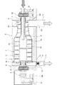
図1はこの発明の実施の形態1による回転式固液分離装置を示す概略断面図である。
この実施の形態1の回転式固液分離装置は、原液(原汚泥)を分離物と分離液に分離する回転式固液分離機1と、該回転式固液分離機1の回転支軸(回転軸)7を支持する回転支持器20と、ガスの流入を防止するガス流入防止器12とから主要部が構成されている。
1 is a schematic cross-sectional view showing a rotary solid-liquid separator according to
The rotary solid-liquid separation device according to the first embodiment includes a rotary solid-
この実施の形態1において、前記回転式固液分離機1は、一端側に分離液排出口2aを有し且つ他端側に分離物排出口2bを有するケーシング2と、このケーシング2内に回転可能に配設され、軸方向一端側が漸次小径に形成された円筒形状の外胴ボウル3と、この外胴ボウル3内に配設されて該外胴ボウル3と同一方向に回転する内胴スクリュウ4と、前記外胴ボウル3と前記内胴スクリュウ4とに回転差を与えるギアボックス(差速調整機)5と、前記外胴ボウル3および前記内胴スクリュウ4を回転駆動する回転駆動機6Aと、前記内胴スクリュウ4の回転数を調整する回転調整駆動機6Bとを備え、前記内胴スクリュウ4内に供給された原液を分離物と分離液とに固液分離するスクリュウデカンタ型遠心分離機からなっている。
In the first embodiment, the rotary solid-
このような回転式固液分離機(遠心分離機)1において、外胴ボウル3および内胴スクリュウ4は個々に回転支軸7,8を有しており、このうち外胴ボウル3両側の回転支軸7が回転支持器20によって支持されている。
したがって図1では、回転式固液分離機1の両側に回転支軸7を支持する回転支持器20が設けられているが、該回転支持器20は、回転式固液分離機1の左右いずれか一方の回転支軸7に設けてもよい。
In such a rotary solid-liquid separator (centrifugal separator) 1, the
Accordingly, in FIG. 1, a
外胴ボウル3の回転支軸7は、一方がケーシング2の一端(図1の紙面上で右端)から突出して回転支持器20に支持され、他方もケーシング2の他端(図1の紙面上で左端)から突出して回転支持器20に支持され、前記ギアボックス5に連結されている。
前記外胴ボウル3の回転支軸7の一方(図1の紙面上で右側)の内側には、内胴スクリュウ4の回転支軸8と汚泥供給管9が配置されている。また、回転支軸7の他方(図1の紙面上で左側)の内側にも、内胴スクリュウ4の回転支軸8が延伸し、ギアボックス5に連結されている。
One of the
A
外胴ボウル3は、伝動ベルト18を介して回転駆動機6Aの駆動により回転し、外胴ボウル3内に回転可能に配置され且つ内胴ベアリングで支持されている内胴スクリュウ4も外胴ボウル3に同伴して回転する。そして内胴スクリュウ4の回転数は、回転調整駆動機6Bの駆動が伝動ベルト19を介してギアボックス5に伝達されることにより、調整される。
The
前記内胴スクリュウ4の内胴内部には原液供給室4aが形成され、この原液供給室4aは、前記内胴スクリュウ4の内胴壁部に設けられた開口(原液供給口)4bを介して前記外胴ボウル3内に連通している。また、前記外胴ボウル3の大径側端面には分離液溢流口3aが設けられ、かつ小径端側外周には分離物流出口3bが設けられている。
A stock
前記ケーシング2の分離液排出口2aには、フレキシブル継手10を介して分離液移送管11が接続されるが、それらのフレキシブル継手10と分離液移送管11との間にはガス流入防止器12が設けられている。このガス流入防止器12は、分離液移送管11を介して回転式固液分離機1から排出された分離液(濃縮分離液や脱水分離液など)や分離物(濃縮汚泥や脱水汚泥など)から発生する腐食性ガスが回転式固液分離機1内や回転支持器20内に流入するのを防止するためのものである。一方、前記ケーシング2の分離物排出口2bには分離物排出管13が接続されている。なお、前記分離液移送管11は分離液貯留槽に、また、前記分離物排出管13は分離物貯留槽に接続されるのが一般的である。
A separation
前記ガス流入防止器12としては、まず代表例として開閉弁が挙げられ、電動弁、電磁弁、空気作動弁、手動弁を用いるが、これに限らず腐食性ガスの流入を確実に防止できる弁であれば、これに限るものではない。
また、弁の種類としては、仕切弁(ゲートバルブ)、ボール弁、バタフライ弁、偏心構造弁などを用いるが、これに限るものではない。
とくに自動運転を行う場合には、電動バタフライ弁を用いるのが好ましい。
なお、仕切弁、ボール弁、偏心構造弁を用いる場合には、接液部にゴムライニング等の防蝕処理を施すことが望ましい。
As the
Moreover, as a kind of valve, although a gate valve, a ball valve, a butterfly valve, an eccentric structure valve, etc. are used, it is not restricted to this.
In particular, when performing automatic operation, it is preferable to use an electric butterfly valve.
In addition, when using a gate valve, a ball valve, and an eccentric structure valve, it is desirable to perform a corrosion-proof treatment such as rubber lining on the liquid contact portion.
前記ガス流入防止器(開閉弁)12の設置場所としては、回転式固液分離機1の分離液移送管11や分離物排出管13に設けるが、これに限るものではなく、回転式固液分離機1の分離液排出口2aや分離物排出口2bに、また、これらに接続する配管の取付部(フランジ)やその周辺に設けてもよい。
また、構造上、ガス流入防止器12の設置ができない場合には、分離液移送管11と分離液貯留槽との接続部やその周辺、分離物排出管13と分離物貯留槽との接続部やその周辺に開閉弁を設置してもよい。
The gas inflow preventer (open / close valve) 12 is installed in the separated
In addition, when the
前記ガス流入防止器12は、回転式固液分離機1の分離液排出口2aと分離液移送管11との間に設けたフレキシブル継手10の下流側(分離液貯留槽側)に、また分離物排出口2bと分離物排出管13との間にフレキシブル継手を設けて該フレキシブル継手の下流側(分離物貯留槽側)に設置することが好ましい。
The
なお、上記回転式固液分離機1に接続する分離液移送管11や分離物排出管13に、他の配管(例えば別途設置されている回転式固液分離機用の分離液移送管や分離物排出管など)が接続している場合には、他の配管から腐食性ガスが流入することを防止するため、他の配管が接続する上流側(回転式固液分離機1側)にガス流入防止器12として開閉弁を設けることが望ましい。
The separation
前記ガス流入防止器12として適用する開閉弁の動作としては、該開閉弁に例えば電動バタフライ弁を採用した場合、全閉全開リミットスイッチ付とし、回転式固液分離機1の運転開始を条件として、全開リミットスイッチがON状態、運転終了を条件として全閉リミットスイッチがON状態となるように制御する。なお、回転式固液分離機1の運転が短時間であるなど開閉弁の開閉回数が少ない場合は手動弁を採用すればよく、この場合、設備を簡便化できる。
As an operation of the on-off valve applied as the
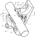
次に前記回転支持器20の詳細構造について説明する。
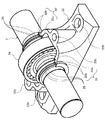
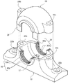
図2および図3は図1中の回転支持器を一部切欠して示す斜視図、図4は図2および図3中の上部ハウジングを示す斜視図である。
図2から図4に示すように、前記回転支持器20は、上下に2分割可能なハウジングボックス21を備えている。このハウジングボックス21は、図示しない台座に固定される基部ハウジング22と、該基部ハウジング22上に着脱可能に装着される上部ハウジング23とから形成されて、前記回転支軸7の両端側に嵌着されたベアリング24を保持している。
Next, the detailed structure of the
2 and 3 are perspective views showing the rotary supporter in FIG. 1 with a part cut away, and FIG. 4 is a perspective view showing the upper housing in FIGS. 2 and 3.
As shown in FIGS. 2 to 4, the
前記基部ハウジング22は、半円形状の内周面に形成された凹溝からなってベアリング24の外輪半周部位を嵌合させるベアリング取付用の嵌合凹部22aと、前記台座に取り付け固定するためのアンカーボルト(図示せず)を挿通させるための固定ボルト穴22bと、前記上部ハウジング23を締め付け固定する締結ボルト25を螺合させるためのボルト螺合孔22cと、ハウジングボックス21内の潤滑油が漏れ出さないようにシールする環状のオイルシール(Z型ゴムシール)37を嵌合させるオイルシールみぞ22dを有する構造となっている。
The
前記上部ハウジング23は、半円形状の内周面に形成されて前記基部ハウジング22の嵌合凹部22aと対称形状をなし、前記ベアリング24の外輪の残り半周部位を嵌合させるベアリング取付用の嵌合凹部23aと、前記締結ボルト25を挿通させるボルト挿通孔23b(図4参照)と、ハウジングボックス21内の潤滑油が漏れ出さないようにシールする環状のオイルシール(Z型ゴムシール)37を嵌合させるオイルシールみぞ23dを有する構造となっている。いわゆる「密封式接触装置(接触型シール)」と言われる構造である。
The
したがって、前記回転支持器20は、台座にアンカーボルトとナットで固定された基部ハウジング22の嵌合凹部22aに対して回転支軸7を支持するベアリング24の外輪半周部位を嵌合させた後、該ベアリング24の外輪の残り半周部位に上部ハウジング23の嵌合凹部23aを嵌合させ、この状態で上部ハウジング23のボルト挿通孔23bを介して基部ハウジング22のボルト螺合孔22cに締結ボルト25を螺合緊締することにより組み立てられている。換言すると、前記回転支軸7のベアリング24は、基部ハウジング22の嵌合凹部22aと上部ハウジング23の嵌合凹部23aとに嵌合されて締結ボルト25により基部ハウジング22と上部ハウジング23とで挟持固定され、締結ボルト25を取り外すことによって基部ハウジング22から上部ハウジング23を外すことができるようになっている。
Therefore, after the
前述のように組み立てられた回転支持器20において、ハウジングボックス21内には、ベアリング24の内輪と外輪との間やその近傍に潤滑油を供給する潤滑油供給部材27として潤滑油供給ノズル27aが配設されている。この潤滑油供給ノズル27aには潤滑油供給管26が接続されている。また、ハウジングボックス21内には潤滑油排出管28が接続されている。
In the
以上において、前記基部ハウジング22および上部ハウジング23は、FC200,FC250などの鋳物が好適であるが、耐性があり加工できるものであれば、どのようなものでも良い。また、上部ハウジング23の基部ハウジング22への装着は、通常、合わせマークやリーマピン等で位置合わせして、2本または4本のボルトで止めるが、確実に装着できる方法であれば、これに限るものではない。さらに、基部ハウジング22の台座への固定は、通常アンカーボルトで行うが、確実に台座へ固定できる方法であれば、これに限るものではない。
In the above description, the
また、前記潤滑油供給部材27としては、耐食性に優れたステンレス製でベアリング24へ直接潤滑油を供給できるものが好ましいが、これに限定されるものではなく、確実に潤滑油をハウジングボックス21内に供給できるものであればよい。例えば、図2に示した潤滑油供給ノズル27aのように、先端がノズル状になっていたり、先端に噴射ノズルが配設されていたりするものが好ましく、必要に応じて回転可能としてもよく、確実に潤滑油をハウジングボックス21内に供給できるものであれば如何なる構造のものでもよい。
とくに、潤滑油をベアリング24やその近傍に噴射する潤滑油供給ノズル27aを採用した場合、潤滑油圧送ポンプから送られてくる潤滑油を即座に且つ確実にベアリング24(詳しくは、ベアリング24の内輪と外輪との間)へ噴射させることができ、回転支軸7の安定した滑らかな回転およびベアリング24の機能発揮に大変有効である。
The lubricating
In particular, when the lubricating
また、図3に示したように、潤滑油供給部材27として潤滑油はねかけ板27bを採用することができる。この潤滑油はねかけ板27bは、回転支軸7の外周に配設され、一部がハウジングボックス21内の底部に貯留されている潤滑油に浸かっていて、回転支軸7の回転により回転して潤滑油をベアリング24やその近傍にはねかけるものであり、通常潤滑油をはねあげやすいように複数の貫通孔Sが設けられた円盤形状であるが、これに限るものではない。潤滑油はねかけ板27bは、ステンレスなど腐食しにくいものを用い、ハウジングボックス21内で回転支軸7と一体に回転可能で、一部が潤滑油に浸かる大きさであれば如何なる構造のものでもよく、基部ハウジング22および上部ハウジング23の内壁とベアリング24との間に、片側のみに、または両側に設ける。また、複数の貫通孔Sに代えて、潤滑油を掬い上げるように加工された受け皿状のものやブラシ状のものを採用してもよい。
とくに、潤滑方式がいわゆる「はねかけ方式、油浴方式」の場合、潤滑油はねかけ板27bを採用することにより、ハウジングボックス21内の底部に貯留する潤滑油を連続して且つ確実にベアリング24やその近傍にはねかけることができ、回転支軸7の安定した滑らかな回転およびベアリング24の機能発揮に大変有効である。
Further, as shown in FIG. 3, a lubricating
In particular, when the lubrication system is a so-called “splash system, oil bath system”, the lubricant stored in the bottom of the
次に、前記実施の形態1による回転式固液分離装置の動作を説明する。
回転駆動機6Aの起動による回転式固液分離機1の運転時にはガス流入防止器(開閉弁)12は開放されている。このような回転式固液分離機1の運転状態では、高速で回転している内胴スクリュウ4の原液供給室4a内に原液供給管9から原液(原汚泥)が供給される。原液供給室4a内に供給された汚泥は、原液供給室4a内で加速されて開口4bから外胴ボウル3内に供給される。外胴ボウル3内に供給された汚泥は、遠心力の作用で固液分離され、その分離液は、内胴スクリュウ4のスクリュウ羽根間を螺旋状に回転しながら、外胴ボウル3の大径側端面の分離液溢流口3aからケーシング2の分離液排出口2aおよび分離液移送管11を介して系外に排出される。一方、前記固液分離後の汚泥は、内胴スクリュウ4の回転により、外胴ボウル3の小径側へ移送されながら圧密にされた後、外胴ボウル3の最も小径となった端部の分離物流出口3bから分離物排出管13を介して系外に排出される。
Next, the operation of the rotary solid-liquid separator according to the first embodiment will be described.
The gas inflow prevention device (open / close valve) 12 is opened during the operation of the rotary solid-
回転式固液分離機1の運転休止時にガス流入防止器12が開放状態のままになっていると、分離液移送管11から排出された濃縮分離液から発生する腐食性ガスが前記分離液移送管11を介して回転式固液分離機1内および回転支持器20内に侵入してくるので、回転式固液分離機1の運転休止時には、前記ガス流入防止器(開閉弁)12が閉鎖することにより腐食性ガスの侵入が防止される。
If the
以上説明した実施の形態1によれば、回転式固液分離機1の分離液排出口2aにガス流入防止器12を設けたことにより、回転式固液分離機1から排出された分離物(濃縮汚泥や脱水汚泥など)や分離液(濃縮分離液や脱水分離液など)から発生する腐食性ガスが回転式固液分離機1内へ流入するのを確実に遮断・防止し、本体や回転支持器等の機器や構成部材の腐食を防止することができるという効果がある。
According to the first embodiment described above, by providing the gas
とくに、回転式固液分離機1が複数も設けられていて交互に稼動・休止させる施設であっても、また、運転が休止している夜間であっても、休止している回転式固液分離機1への腐食性ガスの侵入を食い止めることができるため、作業環境や機器設置環境を改善でき、作業者の安全管理、機器保全、修理交換回数の削減に有効である。また、機器寿命の短縮を防ぐことができ、安定して固液分離機能を発揮させることができるという効果がある。
In particular, even in a facility where a plurality of rotary solid-
また、この実施の形態1の回転式固液分離装置では、回転式固液分離機1の回転支軸7を支持する回転支持器20のハウジングボックス21を基部ハウジング22と上部ハウジング23とに上下2分割できるように構成したので、回転式固液分離機1のメンテナンス時やベアリング交換時に、回転式固液分離機1を台座から取り外さなくても、締結ボルト25を取り外すだけで前記上部ハウジング23を基部ハウジング22から簡単に外すことができ、このため回転軸支持器20のハウジングボックス21内を容易に点検でき、また手際よくハウジングボックス21内のベアリング24を交換することができ、回転機器のメンテナンス作業性が格段に向上するという効果がある。
Further, in the rotary solid-liquid separator of the first embodiment, the
とくに、汚泥などが供給された上で高速回転する回転式固液分離機(遠心分離機)1に前記回転支持器20を用いた場合、前述のようにハウジングボックス21を上下に2分割できるため、遠心分離機の定期点検(オーバーホール)時には、基部ハウジング22から遠心分離機本体のみを取り外せばよく、オーバーホール終了後は基部ハウジング22に遠心分離機本体を戻すだけでよい。このように基部ハウジング22は元のままで遠心分離機の定期点検を行うことができるので、遠心分離機の設置・据付時に行うような精密な水準(水平)を取る作業を省くことができる。
In particular, when the
このように、ハウジングボックス21を上下に2分割できるため、日頃の維持管理業務を確実に実施できるだけでなく、ベアリング24の状況や回転支軸7の周りなど機械中心部の状況を簡便に確認作業できると共に、異常の早期発見にも役立つという効果がある。また、修理が必要な回転体と予備の回転体を容易に交換でき、速やかに定常運転を再開することができるという効果がある。
As described above, since the
また、遠心分離機をオーバーホールする際も、基部ハウジング22から取り外した遠心分離機の再設置・据付(位置合わせなど)がとても簡単で、効率的に作業を行うことができるという効果がある。そして、日頃の維持管理やオーバーホールを適切且つ確実に実施することができ、これにより、遠心分離機を長期間にわたり保守でき、安定して機能を発揮させることができるという効果がある。加えて、基部ハウジング22の両側に設けられたオイルシールみぞ22dと上部ハウジング23の両側に設けられたオイルシールみぞ23dとにより形成される回転支軸7の外周面を取り囲む環状の2本のみぞに、それぞれオイルシール(Z型ゴムシール)37を装着してシールするので、ハウジングボックス21内から外部に漏れ出そうとする(飛散しようとする)潤滑油をハウジングボックス21内に留まらせることができ、潤滑油の漏れ出しによる周辺の汚損や潤滑油の浪費を抑制することができるという効果も得られる。なお、オイルシールとしては、いわゆるZ型ゴムシールが適しているが、これに限定するものではなく、確実に潤滑油をシールできるものであれば、材質や形状は問わない。
In addition, when the centrifuge is overhauled, the centrifuge removed from the
さらに、前記回転支持器20を備えた遠心分離機を、正規の技術者が、規格化された手順に従って、製造されるものの内10%にも満たない稀少で高品質なベアリング(P5〜P6クラス)等の部品を用いて、維持管理、部品交換、オーバーホールすることにより、遠心分離機をより長期間にわたり保守でき、安定して機能を発揮させることができるという効果がある。あえて換言すれば、前述した構造の回転支持器20を備えていない遠心分離機を、技術を習熟していない作業者が、適宜、汎用品を用いて、維持管理、部品交換、オーバーホールすることは、長期間にわたる保守どころか、安定した運転さえも危うくするが、本発明はこのような事態を回避することに有効である。
Furthermore, a centrifuge equipped with the
実施の形態2.
図5はこの発明の実施の形態2による回転式固液分離装置を示す概略断面図であり、図1と同一部分には同一符号を付して重複説明を省略する。
前記実施の形態1の回転式固液分離装置では、回転式固液分離機1の分離液移送管11にのみガス流入防止器12を設けたが、この実施の形態2の回転式固液分離装置では、分離物排出管13を介して回転式固液分離機1から排出された分離液(濃縮分離液や脱水分離液など)や分離物(濃縮汚泥や脱水汚泥など)から発生する腐食性ガスが回転式固液分離機1内や回転支持器20内に流入するのを防止するため、回転式固液分離機1の分離液排出系統と分離物排出系統の両方にガス流入防止器として、分離液移送管11に電動弁12Aを、分離物排出管13に手動弁12Bを設けたものであり、前記電動弁12Aは分離液移送管11の下流側に設けられ、前記手動弁12Bは分離物排出口2bに接続する形で設けられている。
FIG. 5 is a schematic sectional view showing a rotary solid-liquid separator according to
In the rotary solid-liquid separation device of the first embodiment, the gas
このように、回転式固液分離機1の分離液排出系統と分離物排出系統の両方に電動弁12Aと手動弁12Bを設けたことにより、排出された分離液および分離物から発生する腐食性ガスが、分離液排出系統や分離物排出系統から回転式固液分離機1内や回転支持器20に侵入するのを一層確実に防止することができると共に、前記実施の形態1と同様に効果を奏する。
Thus, by providing the motor operated
実施の形態3.
図6はこの発明の実施の形態3による回転式固液分離装置を示す概略断面図であり、図1および図5と同一または相当部分には同一符号を付して重複説明を省略する。
この実施の形態3の回転式固液分離装置では、分離液移送管11に排気ファン14の吸込側を接続すると共に、分離物排出口2bと分離物排出管13の接続部にはガス流入防止器としての遮蔽板15を、シール部材(図示せず)を介して開閉可能に設けたものである。
6 is a schematic cross-sectional view showing a rotary solid-liquid separator according to
In the rotary solid-liquid separation device according to the third embodiment, the suction side of the
すなわち、この実施の形態3では、ガス流入防止器として排気ファン14と遮蔽板15を採用し、前記排気ファン14は分離液移送管11に接続して該分離液移送管11内で発生した場合の腐食性ガスが回転式固液分離機1内に流入しないようにしたものである。なお、前記排気ファン14は分離物排出管13にも設けてよく、その排気ファン14で吸引した腐食性ガスは、通常脱臭装置で処理することが望ましい。
前記排気ファン14は、一般的な送風機と同様の構造でよいが、PVC製など耐食性のあるものを採用する。
That is, in the third embodiment, the
The
前記排気ファン14の設置場所は、前記実施の形態1で説明したガス流入防止器(開閉弁)12の設置場所と同様である。ただし、排気ファン14と分離液移送管11とを接続するガス吸引管の開口に分離液や分離物が流入してこないように、カバーを取り付けるなどの流入防止構造とするものである。
The installation location of the
前記排気ファン14の動作としては、回転式固液分離機1の運転終了を排気ファン14の運転開始条件とし、回転式固液分離機1の運転開始を排気ファン14の運転停止の条件として自動制御する。また、排気ファン14の運転停止を回転式固液分離機1の運転開始条件とする自動制御としてもよい。
As the operation of the
一方、前記遮蔽板15としては、電動式、電磁式、空気作動式、手動式のスライドする遮蔽板を使用するが、これに限らず腐食性ガスの流入を確実に防止できる遮蔽板であれば、これに限るものではない。また、前記遮蔽板15は、通常耐食性のある硬質塩化ビニル(PVC)等のプラスチック製を採用し、平板状、湾曲状、角形、丸形など、密閉性を確保できる形状とする。
なお、前記遮蔽板15の設置場所は、前記実施の形態1で説明したガス流入防止器(開閉弁)12の設置場所と同様である。
On the other hand, as the shielding
The installation location of the shielding
前記遮蔽板15の動作も前記実施の形態1で説明したガス流入防止器12と同様であるが、前記遮蔽板15は比較的操作が簡便であるため、例えば排出時間が限られた分離物排出管13に手動式の遮蔽板15を採用してもよい。その操作は、回転式固液分離機1の運転開始時に遮蔽板15を引き抜き、回転式固液分離機1の運転終了時に遮蔽板15を挿入すればよい。
The operation of the shielding
以上説明した実施の形態3によれば、分離液移送管11より排出された分離液から発生し、前記分離液移送管11を逆流して回転式固液分離機1内に侵入しようとする腐食性ガスを排気ファン14で外部に排出することができると共に、分離物排出管13から排出された分離物(汚泥)から発生し前記分離物排出管13を介して回転式固液分離機1内に侵入しようとする腐食性ガスを遮蔽板15で遮断して回転式固液分離機1内や回転支持器20内に腐食性ガスが侵入するのを防止することができるという効果がある。
According to the third embodiment described above, corrosion is generated from the separated liquid discharged from the separated
実施の形態4.
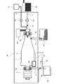
図7はこの発明の実施の形態4による回転式固液分離装置を示す概略図であり、図1および図5,6と同一または相当部分には同一符号を付して重複説明を省略する。
この実施の形態4の回転式固液分離装置は、パッケージ型遠心分離機からなるもので、前記実施の形態1〜前記実施の形態3と同一構造の回転式固液分離機(遠心分離機)1をパッケージケース16内に納めると共に、該パッケージケース16の外部に原液(汚泥)供給槽40と薬品供給タンク41および分離液貯留槽42と分離物貯留槽43のそれぞれを配設している。
FIG. 7 is a schematic diagram showing a rotary solid-liquid separator according to
The rotary solid-liquid separator of the fourth embodiment is composed of a package-type centrifuge, and the rotary solid-liquid separator (centrifugal separator) having the same structure as that of the first to third embodiments. 1 is housed in the
前記原液供給槽40には、前記実施の形態1〜前記実施の形態3で説明した原液(汚泥)供給管9が接続され、該原液供給管9に設けられた原液(汚泥)圧送ポンプ44によって、前記原液供給槽40内の原液が原液供給管9を介して回転式固液分離機1内(詳しくは、内胴スクリュウ4の原液供給室4a(図1,図5,図6参照))に圧送・供給されるようになっている。
The stock solution (sludge)
前記薬品供給タンク41には薬品供給管45が接続され、該薬品供給管45に設けられた薬品供給ポンプ46によって、前記薬品供給タンク41の凝集剤が回転式固液分離機1内に供給されるようになっている。
前記分離液貯留槽42は、これに接続された分離液移送管11からの分離液(濃縮分離液や脱水分離液など)を受け入れて一旦貯留しておくものである。
前記脱水汚泥貯留槽43は、これに接続された分離物排出管13から分離物(濃縮汚泥や脱水汚泥など)を受け入れて一旦貯留しておくものである。
A
The separation
The dewatered
そして、前記の汚泥供給管9と分離液移送管11および分離物排出管13のそれぞれに開閉弁47,48,49が個々に設けられている。これらの開閉弁47,48,49において、少なくとも分離液移送管11の開閉弁48と分離物排出管13の開閉弁49はガス流入防止器として機能するものである。
On-off
回転式固液分離機1の外胴ボウル3における分離液移送管11の接続部付近において、パッケージケース16には分離液監視ボックス50が設けられ、この分離液監視ボックス50にはパッケージケース16内に通じるガス吸引管51が接続されている。このガス吸引管51は、パッケージケース16内に流入また発生する腐食性ガスをガス処理設備に導くものである。ただし、ガス吸引管51での腐食性ガスの吸引によりパッケージケース16内が負圧になり、かえって分離液移送管11や分離物排出管13からパッケージケース16内へ腐食性ガスを導いてしまうため、分離液貯留槽42や分離物貯留槽43とパッケージケース16とを隔絶する部材(遮蔽弁や遮蔽板)を設ける。
In the vicinity of the connection portion of the separation
また、前記分離液移送管11における開閉弁48の上流側には、パッケージケース16の底部から雑排水を排出する雑排水排出管52が接続されている。さらに、前記分離液移送管11における開閉弁48の下流側にはガス放散管53が接続されている。
Further, on the upstream side of the on-off
パッケージ型遠心分離機の場合、パッケージケース16内で発生した雑排水を、雑排水排出管52により分離液移送管11を介して排出するが、雑排水排出管52と分離液移送管11との接続個所は、分離液貯留槽42で発生する腐食性ガスが雑排水排出管52を介してパッケージケース16内に流入しないように、前述のように開閉弁48の上流側(遠心分離機側)に設定するか、前記雑排水排出管52にUトラップを設ける。そうすることにより、前記雑排水排出管52からパッケージケース16内への腐食性ガスの流入を防止することができる。
In the case of a package type centrifuge, miscellaneous wastewater generated in the
前記ガス放散管53は、分離液移送管11および分離液貯留槽42で遮断された腐食性ガスの逃げ道となるものである。遮断された腐食性ガスを滞留させると、配管自体に、または分離液貯留槽42や分離物貯留槽43(関連機器を含む)に悪影響を及ぼすので、この実施の形態4では、腐食性ガスを大気中に放散させる前記ガス放散管53や、腐食性ガスをガス処理設備へ導くガス移送管を前記開閉弁48,49の下流側に設けることとしたものである。
The
なお、腐食性ガスの回転式固液分離機1への流入を防止するため、例えば図7の遠心分離機により汚泥を脱水する施設においては、脱水する原汚泥を遠心分離機へ供給するために設けられた原液供給槽(汚泥ストレージタンク)40と遠心分離機とを接続する原液供給管9等にガス流入防止器(開閉弁47)を設けてもよい。
In order to prevent the corrosive gas from flowing into the rotary solid-
原液供給管9からも腐食性ガスが発生するため、前記原液供給管9にガス流入防止器としての開閉弁や遮断板、ガス吸引ファンを設けてもよい。なお、原液(原汚泥)を遠心分離機に供給する原液圧送ポンプ44として一軸ねじ式ポンプを採用した場合、腐食性ガスの遠心分離機への流入を遮断できるため、一軸ねじ式ポンプがガス流入防止器の役目を果たす。
Since corrosive gas is also generated from the stock
以上説明した実施の形態4によれば、回転式固液分離機1の運転休止時に分離液移送管11および分離物排出管13のそれぞれを閉じておくことにより、とくに分離液貯留槽42や分離物貯留槽43の密封性を悪臭防止のために高くしても、それらの分離液貯留槽42内の分離液や分離物貯留槽43内の分離物から発生した腐食性ガスが分離液移送管11や分離物排出管13を介して回転式固液分離機1内や回転支持器20内に侵入するのを確実に防止することができるという効果がある。
According to the fourth embodiment described above, the separated
また、前記分離液移送管11における開閉弁48に下流側にはガス放散管53を接続したことにより、前記開閉弁48を閉じた状態で分離液貯留槽42内の分離液から発生した腐食性ガスを前記ガス放散管53から系外に排出することができるという効果がある。
さらに、回転式固液分離機1に設けた分離液監視ボックス50によって、回転式固液分離機1内の分離液の状態を監視することができると共に、回転式固液分離機1内で発生した腐食性ガスをガス吸引管51から系外に排出することができるという効果がある。さらには、回転式固液分離機1の運転時(開閉弁48の開弁時)には、パッケージケース16内に発生した雑排水を雑排水排出管52によって分離液移送管11の分離液に合流させて分離液貯留槽42に送り込みことができるという効果がある。
Further, a
Furthermore, the separation
実施の形態5.
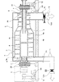
図8はこの発明の実施の形態5による回転式固液分離装置を示す断面図であり、図1および図7と同一または相当部分には同一符号を付して説明する。
この実施の形態5の回転式固液分離装置は、回転式固液分離機としてスクリュープレス分離機54をケーシング2内に配設したもので、該スクリュープレス分離機54は、パンチングメタル、金属製スクリーン、多重円板などで形成されて分離液を内側から通過させる円筒状の分離部材55と、該分離部材55内に挿入配置されて回転駆動される回転スクリュー56とを備え、前記回転スクリュー56両端の回転軸56aを回転支持器20で支持した概要構造となっている。なお、前記ケーシング2内の上部には、前記分離部材55に洗浄水を噴射して該分離部材55の目詰まりを防止する洗浄水噴射ノズル57が配設されている。
8 is a cross-sectional view showing a rotary solid-liquid separator according to
The rotary solid-liquid separator of
このようなスクリュープレス分離機54においては、ケーシング2の分離液排出口2aにフレキシブル継手58Aを接続し、該フレキシブル継手58Aと分離液移送管11との間にガス流入防止器としての開閉弁59を介在させている。そして、前記開閉弁59が開状態でのスクリュープレス分離機54の運転時にケーシング2内の分離液が前記フレキシブル継手58Aおよび開閉弁59を介して分離液貯留槽42内に移送・貯留される。一方、前記ケーシング2の分離物排出口2bにもフレキシブル継手58Bが接続されて該フレキシブル継手58Bに分離物排出管13が接続されている。そして、前記スクリュープレス分離機54で濃縮分離された分離物がフレキシブル継手58Bを介して分離物排出管13から系外に排出回収される。
In such a
以上説明した実施の形態5のスクリュープレス分離機54においても、該スクリュープレス分離機54の運転休止時に開閉弁59を閉じておくことにより、分離液貯留槽42内の分離液から発生する腐食性ガスが分離液移送管11からケーシング2内に侵入するのを防止することができ、これにより、腐食性ガスに起因した分離機42の構成部材の腐食(錆び発生)等を防止することができるという効果がある。
Also in the
実施の形態6.
図9はこの発明の実施の形態6による回転式固液分離装置を示す概略断面図である。
この回転式固液分離装置は遠心ろ過分離機(遠心ろ過濃縮機)60からなるもので、該遠心ろ過分離機60は、ケーシング61内に回転可能に配設された円錐形状の回転バスケット62と、該回転バスケット62の内側に張り付けられたろ布63と、前記回転バスケット62内に原液を供給する原液供給管64と、前記ろ布63に洗浄水を噴射する洗浄水噴射ノズル65とを備え、前記回転バスケット62の底部に一体の垂直な回転軸62aを回転支持器20で支持した概要構造となっている。
Embodiment 6 FIG.
FIG. 9 is a schematic sectional view showing a rotary solid-liquid separator according to Embodiment 6 of the present invention.
This rotary solid-liquid separation device is composed of a centrifugal filtration separator (centrifugal filtration concentrator) 60, and the
前記ケーシング61は、前記ろ布63および回転バスケット62を通過した分離液を受け入れる環状の分離液室61aと、前記ろ布63で捕捉された分離物を前記回転バスケット62の上端から受け入れる分離物室61bを形成している。前記分離液室61aの底部には分離液移送管66が接続され、該分離液移送管66にはガス流入防止器としての開閉弁67が設けられている。
The
このように構成された遠心ろ過分離機60の運転時には、開閉弁67が開かれて回転バスケット62が回転駆動され、この状態において、原液供給管64から回転バスケット62の底部に汚泥等の原液が供給されると、原液中の水分は、ろ布63を通過することにより、ろ液として分離されると共に、ろ布63面には浮遊物質等の分離物(汚泥)が捕捉される。
前記ろ布63を通過した分離液(ろ液)は分離液室61aに流入した後、分離液移送管66で分離液貯留槽に送られる。
一方、ろ布63面に捕捉された分離物は、回転バスケット62の回転により、ろ過濃縮作用を受けながら回転バスケット62の円錐壁面を徐々に上昇し、該回転バスケット62の上端から分離物室61bへ流出し、高濃度濃縮液として回収される。
During operation of the
The separation liquid (filtrate) that has passed through the
On the other hand, the separated matter captured on the surface of the
以上説明した遠心ろ過分離機60においても、分離液移送管66にガス流入防止器としての開閉弁67を設けたこと、分離物排出管68にガス流入防止器としての開閉弁69を設けたこと、および回転バスケット62の回転軸62aを回転支持器20で支持したことにより、前記実施の形態1と同様の効果を奏する。
Also in the
実施の形態7.
図10(A)はこの発明の実施の形態7による回転式固液分離装置としての回転加圧式分離機70を示す径方向断面図、図10(B)は図10(A)の軸方向断面図である。
この実施の形態7の回転加圧式分離機70は、円板状の2枚の金属フィルター72a,72bを両側に有するフィルタードラム72を円形状のケーシング71内に回転可能に納め、そのフィルタードラム72の回転軸73を回転支持器20で支持した概要構造となっている。
FIG. 10A is a radial sectional view showing a
In the
このような回転加圧式分離機70において、フィルタードラム72内には原液供給管74から原液が圧送・供給されるようになっており、ケーシング71の底部に設けられた分離液排出口71aには分離液移送管75が接続され、この分離液移送管75にはガス流入防止器としての開閉弁76が設けられている。なお、図10(A)中の符号77は分離物排出管である。
In such a
前記の回転加圧式分離機70では、開閉弁76を開いた状態でフィルタードラム72が回転駆動され、この状態で原液供給管74からフィルタードラム72内に圧送・供給された原液は、主にフィルタードラム72の回転力による剪断力で圧搾脱水される。すなわち、フィルタードラム72内に圧送・供給された原液は、水分が金属フィルター72a,72bを通過して脱水分離液となり、汚泥等の分離物は前記金属フィルター72a,72bで捕捉される。そして、前記脱水分離液は分離液移送管75から分離液貯留槽に送り込まれ、前記分離物は分離物排出管77から排出されて回収される。
In the
以上説明した回転加圧式分離器70においても、分離液移送管75にガス流入防止器としての開閉弁76を設けたこと、および、フィルタードラム72の回転軸73を回転支持器20で支持したことにより、前記実施の形態1と同様の効果を奏する。
Also in the
実施の形態8.
図11はこの発明の実施の形態8による回転支持器を一部切欠して示す斜視図、図12は図11中のハウジングボックスを示す分解斜視図、図13は図11,12中の基部ハウジングを示す拡大平面図であり、図2から図4と同一部分には同一符号を付して重複説明を省略する。
この実施の形態8の回転支持器20では、基部ハウジング22および上部ハウジング23のそれぞれの両側内周面に複数のみぞ(以下、「油みぞ」という)32,33を設けた点、基部ハウジング22の油みぞ32に排油孔34(図13参照)を設けた点、該排油孔34とハウジングボックス21(基部ハウジング22)内とを連通するオイルドレイン17を設けた点が、前記実施の形態1で適用し説明した回転支持器20と大きく異なる。
11 is a partially cutaway perspective view showing a rotary support device according to
In the
さらに詳述すると、この実施の形態8において、前記油みぞ32,33は、潤滑油供給ノズル27aからハウジングボックス21内に供給された潤滑油が該ハウジングボックス21内から外部に漏れ出す(飛散する)のを防止するために該潤滑油を貯めておくもので、基部ハウジング22の油みぞ32は、基部ハウジング22の両側部に形成されて回転支軸7の軸方向に隣り合う複数(2〜5本、通常3本)の半円弧状の油みぞ32a(1〜2本、通常1本),32b(1〜3本、通常2本)からなっている。これらの油みぞ32a,32bにおいて、ハウジングボックス21の最も内側に位置する油みぞ(以下、「内側油みぞ」という)32aは、該内側油みぞ32aの外側に位置する油みぞ(以下、「外側油みぞ」という)32bよりも、みぞの深さが深く形成されている。
More specifically, in the eighth embodiment, in the
このような基部ハウジング22の油みぞ32と同様に、上部ハウジング23の油みぞ33も、上部ハウジング23の両側部に形成されて回転支軸7の軸方向に隣り合う複数(2〜5本、通常3本)の半円弧状の油みぞ33a,33b(図11参照)からなっている。これらの油みぞ33a(1〜2本、通常1本),33b(1〜3本、通常2本)において、ハウジングボックス21の最も内側に位置する油みぞ(以下、「内側油みぞ」という)33aは、該内側油みぞ33aの外側に位置する油みぞ(以下、「外側油みぞ」という)33bよりも、みぞの深さが深く形成されている。
基部ハウジング22上に上部ハウジング23を装着した状態では、基部ハウジング22の内側油みぞ32aおよび外側油みぞ32bと、上部ハウジング23の内側油みぞ33aおよび外側油みぞ33bとによって、回転支軸7の外周面を取り囲む断面円形環状の油みぞが形成されるようになっている。
Similar to the
In a state where the
そして、下記実施の形態9で詳述するが、ハウジングボックス21の油みぞ32,33に回転自在に嵌合するように回転式固液分離機(例えば遠心分離機)の回転支軸7の外周に同心円形鍔状の突起35を設け、潤滑油がハウジングボックス21内から外部へ漏れ出すのを遮る(シールする)構造とする。
As will be described in detail in
前記排油孔34は、前記油みぞ32に留まる潤滑油を順次排出させるためのもので、その排油孔34は、前記油みぞ32に留まる潤滑油をハウジングボックス21内に返送する構造とすることが望ましい。このため、前記排油孔34は、前記油みぞ32とハウジングボックス21内とを連通する孔となっている。
このような排油孔34は、通常直径1〜30mm程度で、基部ハウジング22の油みぞ32の最も低い位置、すなわち、この実施の形態2では、みぞの深さが最も深い内側油みぞ32aの底部に設けられている。なお、前記排油孔34は、一つの油みぞ32に一つまたは二つ以上を設けてもよく、前述のように複数の油みぞ32a,32bがある場合には、必ずしも内側油みぞ32aに設ける必要はなく、いずれにしろ、油みぞ32a,32bに流れ込んできた潤滑油を適切に排除できる位置・構造であれば、これに限るものではない。
The
Such oil drain holes 34 are usually about 1 to 30 mm in diameter, and in the lowest position of the
前記排油孔34とハウジングボックス21内とを連通するオイルドレイン17は、所望する油みぞ32(実施の形態8では内側油みぞ32a)内の潤滑油のレベル高(油面)に合わせ、立上管の形状とすることが有効である。この実施の形態8では、前記排油孔34に基端を接続したオイルドレイン17の先端を立ち上げてハウジングボックス21内に開口させた立上管形状のオイルドレイン17を設けている。このように、オイルドレイン17は立上管形状とすることが望ましいが、油みぞ32内の潤滑油のレベル高を一定に保持できるものであれば、これに限定されるものではない。
なお、前記オイルドレイン17は、直径1〜30mm程度で、アルミやステンレスなどで製作してもよく、基部ハウジング22と同じ素材でもよく、基部ハウジング22と一体成型してもよい。要するに、排油孔34に接続して油みぞ32の潤滑油をハウジングボックス21内に返送・排除できるオイルドレインであればよい。
The
The
以上説明した実施の形態8によれば、基部ハウジング22および上部ハウジング23の両側部に、これらの側面と平行して両者の組付け合体時に円形環状みぞとなる油みぞ32,33を形成し、これに嵌合する同心円形鍔状の突起35を回転支軸7の外周に設けたので、潤滑油供給ノズル27aからハウジングボックス21内に供給されて該ハウジングボックス21内から外部に漏れ出そうとする(飛散しようとする)潤滑油を、前記突起35で遮ると共に前記油みぞ32,33で留まらせることができ、このため、ハウジングボックス21内から外部への潤滑油の漏れ出しに起因した周辺の汚損および潤滑油の浪費を抑制できるという効果がある。もちろん、潤滑油供給ノズル27aに代り、潤滑油はねかけ板27bを用いた場合にも、同様の効果が得られる。
According to the eighth embodiment described above, the
また、基部ハウジング22の油みぞ32に排油孔34を設けると共に、該排油孔34とハウジングボックス21内とをオイルドレイン17で接続し、該オイルドレイン17によって、前記油みぞ32の潤滑油のレベル高を一定に保持できるように構成したので、前記油みぞ32に流れ込んだ潤滑油を前記排油孔34とオイルドレイン17によってハウジングボックス21内に返送できると共に、前記オイルドレイン17によって前記油みぞ32の潤滑油を一定のレベル高に保持できるため、前記油みぞ32の潤滑油が外部へ溢れ出したり、潤滑油不足で回転支軸7およびベアリング24の回転に支障を来したりするのを防止することができるという効果がある。
An
実施の形態9.
図14はこの発明の実施の形態9による回転支持器の要部を示す斜視図であり、図11〜図13と同一部分には同一符号を付して説明する。
この実施の形態9では、上述したように、前記実施の形態8による回転式固液分離機の回転支軸7の外周に同心円形鍔状の突起35を一体に設け、該突起35をハウジングボックス21の油みぞ32,33(図14では上部ハウジング23が取り外されていることにより油みぞ33は図示されていないが、該油みぞ33については図11参照)に回転自在に嵌合して、いわゆる「非密封式接触装置(非接触型シール)」と言われる構造にしたことについて詳説する。
FIG. 14 is a perspective view showing an essential part of a rotary supporter according to
In the ninth embodiment, as described above, the concentric circular bowl-shaped
前記突起35は、油みぞ32,33と接触することを考慮して、加工しやすく柔軟性のある材質、例えば黄銅やステンレスを適宜採用することができ、回転支軸7に直接加工してもよく、また、ブッシュとして別途製作し溶接などで回転支軸7に固定してもよい。
In consideration of the contact with the
以上において、ハウジングボックス21に潤滑油を十分に供給する場合、ベアリング24を覆うハウジングボックス21が確実にシールされていないと、潤滑油が外部に漏れ出し(飛散し)、周辺を汚損させる。そこで、この実施の形態9では、ハウジングボックス21内から潤滑油が漏れ出すのを防止するため、ハウジングボックス21内に油みぞ32,33を設けると共に、回転支軸7の外周には前記油みぞ32,33に嵌合する突起35を設けたものである。
In the above, when the lubricating oil is sufficiently supplied to the
前記油みぞ32,33には、ハウジングボックス21内から外部から漏れ出そうとする潤滑油が前記突起35で遮られて留まる。前記油みぞ32,33に留まる潤滑油量が一定量であれば、前記油みぞ32,33に嵌合し回転支軸7に連動して回転する前記突起35を潤滑する効果がある。しかし、前記油みぞ32,33に多量の潤滑油量が貯まると前記油みぞ32,33から外部に溢れ出し、周辺を汚損させ、また潤滑油を浪費させることになる。そこで、前記油みぞ32,33に排油孔34が設けられているのであり、この排油孔34によって、前記油みぞ32,33に留まる潤滑油を順次排出させる。前記排油孔34は、ハウジングボックス21内に潤滑油を返送する構造とすることが望ましく、油みぞ32,33とハウジングボックス21内部とを連通する孔となっている。
In the
前記油みぞ32,33とハウジングボックス21内部とを連通する排油孔34を設けた場合、前記油みぞ32,33に貯まった潤滑油が殆ど排除されてしまうこともある。そうなると、油みぞ32,33に潤滑油がなくなり、該油みぞ32,33に嵌合し回転支軸7に連動して回転する前記突起35の回転(潤滑)に支障をきたす。そこで、前記ハウジングボックス21内に、排油孔34に連通するオイルドレイン17を設けたのであり、このオイルドレイン17は、所望する油みぞ32の潤滑油のレベル高(油位)に合わせ、立上管形状とすることが有効である。
When the oil drain holes 34 for communicating the
以上説明した実施の形態9によれば、ハウジングボックス21内から外部に漏れ出そうとする(飛散しようとする)潤滑油が突起35で遮られて油みぞ32,33に留まることにより、ハウジングボックス21内の潤滑油が外部に漏れ出したり飛散したりするのを確実に防止できると共に、回転支軸7に連動して前記油みぞ32,33内で回転する突起35を潤滑することができるという効果がある。
According to the ninth embodiment described above, the lubricating oil that is about to leak out (spray) from the inside of the
そして、前記実施の形態8で説明したように、基部ハウジング22の油みぞ32(内側油みぞ32a)に設けた排油孔34と、該排油孔34とハウジングボックス21内とを連通する立上管形状のオイルドレイン17とを有する構造となっているので、前記油みぞ32,33に多量の潤滑油が流れ込んでも該潤滑油を前記オイルドレイン17によってハウジングボックス21内に返送することができ、かつ、前記油みぞ32,23の潤滑油を一定のレベル高に保持できるため、ハウジングボックス21内から外部への潤滑油の漏れ出し、潤滑油の漏れ出しに起因した周辺の汚損および潤滑油の浪費を効率よく確実に抑制できるという効果がある。
As described in the eighth embodiment, the
なお、前記実施の形態9では、回転支軸7の外周に突起35を設け、該突起35を基部ハウジング22の油みぞ32および上部ハウジング23の油みぞ33に嵌合させる構造としたが、前記突起35に代えて前記回転支軸7の外周に環状凹構造の一つまたは二つ以上の嵌合凹部(図示せず)を設け、該嵌合凹部と基部ハウジング22の油みぞ32の側壁および上部ハウジング23の油みぞ33の側壁とを嵌合させる構造としてもよく、この場合も前記実施の形態9と同様の作用効果が期待できる。
In the ninth embodiment, the
実施の形態10.
図15はこの発明の実施の形態10による回転支持器のハウジングボックスを分解状態で示す斜視図、図16は図15中の基部ハウジングを示す拡大平面図であり、図11〜図13と同一部分には同一符号を付して説明する。
この実施の形態10では、上部ハウジング23の軸方向両側部に、該上部ハウジング23の径方向両側部から垂下する板状のガイドプレート36を設けた点が、前記実施の形態8と大きく異なる。
15 is a perspective view showing a housing box of a rotary supporter according to
The tenth embodiment is greatly different from the eighth embodiment in that plate-
前記ガイドプレート36は、基部ハウジング22上に対する上部ハウジング23の組付け接合時において、ハウジングボックス21内の部材等を傷付けないように、また、基部ハウジング22の油みぞ32における内側油みぞ32aの内側壁面にスムーズに接合するように設けられ、基部ハウジング22の油みぞ32と上部ハウジング23の油みぞ33との接続部で基部ハウジング22と上部ハウジング23との接合面間に生じる僅かな隙間をハウジングボックス21の内側から遮るものである。
The
このようなガイドプレート36としては、厚さ1〜10mm程度で、一枚または二枚以上の長方形や円弧状のプレートを適用して上部ハウジング23に配設することが可能であり、その材質は、ステンレスなどで製作してもよく、また、上部ハウジング23と同じ素材で製作したり、上部ハウジング23と一体成型したりしてもよいが、必ずしもこれらに限られるものではない。なお、前記ガイドプレート36は、必要に応じて基部ハウジング22に設けてもよい。
As such a
以上説明した実施の形態10によれば、基部ハウジング22の油みぞ32と上部ハウジング23の油みぞ33との接続部において、基部ハウジング22と上部ハウジング23との接合面間の僅かな隙間をハウジングボックス21の内側から遮るガイドプレート36を上部ハウジング23に設けたので、潤滑油供給ノズル27aからハウジングボックス21内に供給された潤滑油が、ベアリング24や回転支軸7にぶつかって飛び散り、基部ハウジング22と上部ハウジング23との接合面間の僅かな隙間から漏れ出すのを前記ガイドプレート36で防止することができるため、潤滑油の外部漏出による周辺の汚損および潤滑油の浪費を防止することができるという効果がある。もちろん、潤滑油供給ノズル27aに代り、潤滑油はねかけ板27bを用いた場合にも、同様の効果が得られる。
According to the tenth embodiment described above, in the connecting portion between the
前記各実施の形態において、前記実施の形態8〜実施の形態10による回転支持器20は、そのいずれもが前記実施の形態1〜実施の形態7による回転式固液分離装置に適用可能なものである。
In each of the above-described embodiments, the
実施例1.
前記実施の形態1における回転式固液分離機(遠心分離機)1を下水処理施設の汚泥脱水設備に設置して試運転した結果を以下に説明する。
遠心分離機は5台を設置し、該遠心分離機の脱水分離液移送管(脱水汚泥排出管)11に、ガス流入防止器12としての電動式バタフライ弁または手動式バタフライ弁を、分離液移送口に設置したフレキシブル継手の下流側に設置した。
電動式バタフライ弁の場合は、手動運転では運転者が弁の開閉状態を確認し、手動操作にて弁の開閉を行った。自動運転では、制御機器を用いて、遠心分離機の運転開始と同時に、弁が開になり、運転停止時には、遠心分離機本体の回転停止後にタイマー等で遅延させて弁を閉にした。
手動式バタフライ弁の場合は、全開および全閉ともに、リミットスイッチを設け、全開でなければ、遠心分離機を含め全ての機械装置が動かないように設定した。
Example 1.
The results of a trial run with the rotary solid-liquid separator (centrifugal separator) 1 according to
Five centrifuges are installed, and an electric butterfly valve or a manual butterfly valve as a
In the case of an electric butterfly valve, the driver checked the open / closed state of the valve during manual operation, and opened / closed the valve manually. In automatic operation, the valve was opened simultaneously with the start of operation of the centrifuge using a control device, and when the operation was stopped, the valve was closed by delaying it with a timer after the rotation of the centrifuge body stopped.
In the case of a manual butterfly valve, limit switches were provided for both full open and full close, and settings were made so that all mechanical devices including the centrifuge would not move unless fully open.
このように汚泥脱水設備の遠心分離機にガス流入防止器12を備えたことにより、以下のような作用効果が得られた。
(1)硫化水素ガスが主原因となって微生物の作用により湿気分で生じる水滴等が硫酸化し、遠心分離機や関連機器の構成材であるSUS304等のステンレス鋼の腐食(孔蝕、粒界腐食、応力腐食割れ等)を引き起こし、また、遠心分離機においては、内胴スクリュウ羽根の先端に取り付けた耐摩耗材の腐食や剥離を招き、さらにパッケージ型の遠心分離機では、ケーシングの溶接部の粒界腐食なども引き起こしていたが、このような腐食や剥離を防止することができた。
(2)硫化水素等の腐食性ガスは、遠心分離機の高速で回転する回転支軸を支持する回転支持器に使用しているベアリングや潤滑油の劣化を早めてしまう。これは回転支持器内に腐食性ガスが入り込み、ベアリングを腐食させると共に、腐食した破片等が摩耗を促進させ、加えて腐食や摩耗により生じた遺物が潤滑油に混入して劣化を早めるためであり、1年以上使用できる潤滑油が半年も経たずに交換する事態が発生したが、このようなベアリングや潤滑油の劣化を抑制することができ、通常の交換で済んだ。
(3)下水処理場の遠心分離機本体(外胴ボウルや内胴スクリュウなど)が腐食性ガスに曝されると腐食が進み、通常1〜2年のところ、半年程度で修理・補修が必要になる。例えば、内胴スクリュウの先端に取り付けた耐摩耗材(燒結鋼チップ)が腐食性ガスの影響で剥離して回転体内部に多数の傷をつけてしまったり、また外胴ボウルの腐食部分(孔食)を起点としたクラックが発生したり、ケーシングに設けられた点検窓の固定ボルトが腐食したりする。さらに、遠心分離機本体だけでなく、回転支持器、回転センサーや振動センサー等の制御機器、操作盤などといった関連機器の劣化や耐用年数の短縮を招いていた。しかし、この発明のガス流入防止器を備えた遠心分離機では、このような損傷や腐食等による故障、劣化、耐用年数の短縮を防ぐことができた。
(4)腐食性ガスは、遠心分離機の消耗品(ベアリング、パッキング)等にも影響を及ぼし、寿命も著しく低下させる(頻繁な交換が必要になる)。補修工事から数ヶ月後しか経過していないにもかかわらず、ギアボックス(分離液排出口側)のベアリングが腐食して(激しく錆びて)しまい、異常音や異常振動が発生した。そこで、ベアリング周辺の腐食性ガス(硫化水素)濃度を測定した結果、作業環境基準をはるかに超える150ppmという高濃度になっており、作業環境としても機器設置環境としても不適切(危険)であった。しかし、この発明のガス流入防止器を備えた遠心分離機では、腐食性ガス濃度を安全なレベルに抑制でき、加えて臭気を軽減することができた。
Thus, by providing the
(1) Hydrogen sulfide gas is the main cause, and water droplets generated by moisture due to the action of microorganisms are sulfated, and corrosion of stainless steel such as SUS304, which is a component of centrifuges and related equipment (pitting corrosion, grain boundaries Corrosion, stress corrosion cracking, etc.), and in a centrifuge, the wear-resistant material attached to the tip of the inner screw blade is corroded and peeled. In a packaged centrifuge, the welded part of the casing Intergranular corrosion was also caused, but such corrosion and peeling could be prevented.
(2) A corrosive gas such as hydrogen sulfide accelerates the deterioration of bearings and lubricating oil used in a rotary supporter that supports a rotary spindle that rotates at a high speed of a centrifuge. This is because corrosive gas enters the rotating support and corrodes the bearings, and corroded debris accelerates wear, and in addition, remnants generated by corrosion and wear are mixed into the lubricant to accelerate deterioration. Yes, there was a situation where the lubricating oil that can be used for more than one year was replaced in less than half a year, but such deterioration of the bearing and lubricating oil could be suppressed, and normal replacement was sufficient.
(3) When the centrifuge body (outer shell bowl, inner shell screw, etc.) of a sewage treatment plant is exposed to corrosive gas, corrosion progresses, and it usually takes about 1 to 2 years, and repair and repair are required in about half a year. become. For example, the wear-resistant material (sintered steel chip) attached to the tip of the inner cylinder screw may peel off due to the influence of corrosive gas and cause numerous scratches inside the rotating body, or the corroded part (pitting corrosion) of the outer cylinder bowl. ) As a starting point, or the fixing bolt of the inspection window provided on the casing is corroded. Furthermore, not only the main body of the centrifuge, but also related devices such as a rotation supporter, a control device such as a rotation sensor and a vibration sensor, and an operation panel have been deteriorated and the service life has been shortened. However, in the centrifuge provided with the gas inflow preventer of the present invention, it was possible to prevent failure, deterioration, and shortened service life due to such damage and corrosion.
(4) The corrosive gas also affects the consumables (bearings, packing), etc. of the centrifuge, and significantly reduces the life (requires frequent replacement). Despite only a few months after the repair work, the bearing of the gearbox (separate outlet) corroded (violently rusted), causing abnormal noise and vibration. Therefore, as a result of measuring the concentration of corrosive gas (hydrogen sulfide) around the bearings, the concentration was as high as 150 ppm, far exceeding the working environment standard, and it was inappropriate (dangerous) as the working environment and the equipment installation environment. It was. However, in the centrifuge equipped with the gas inflow preventer of the present invention, the corrosive gas concentration can be suppressed to a safe level, and in addition, the odor can be reduced.
実施例2.
排水処理施設におけるスクリュープレス分離機54(図8参照)を用いた汚泥処理設備において、設置されたスクリュープレス分離機54の分離液移送管11に、ガス流入防止器である開閉弁59として電動式バタフライ弁(自動制御弁)を「脱水分離液移送本管にあるフランジ」に設置した。
このように汚泥処理設備のスクリュープレス分離機54に開閉弁59を備えたことにより、以下のような作用効果が得られた。
(1)排水処理施設に設置したスクリュープレス分離機は、設置後、実際の運転を開始(処理する原汚泥が発生)するまで1年近く要する場合があり、その間、スクリュープレス分離機は停止したままであるが、分離液貯留槽42に他の雑排水が流入してくる構造(共用槽)の場合、スクリュープレス分離機が稼動していなくても、分離液貯留槽42から貯留する雑排水に起因して腐食性ガスが発生する。そして、施設(建屋)内を脱臭する脱臭設備が設置・稼動していると、腐食性のガスは「分離液貯留槽(発生場所)−スクリュープレス分離機−建屋−脱臭装置」と流れていき、スクリュープレス分離機内に侵入して腐食を起こすことになるが、このような腐食性ガスの侵入を防止することができる(図8参照)。
(2)スクリュープレス分離機が稼動している場合は、上記実施例1の場合と同様に、腐食性ガスの流入、これによる腐食や劣化を防止することができる。
Example 2
In the sludge treatment facility using the screw press separator 54 (see FIG. 8) in the wastewater treatment facility, the separation
Thus, by providing the on-off
(1) The screw press separator installed in the wastewater treatment facility may take nearly one year after installation until actual operation starts (generation of raw sludge to be processed), during which time the screw press separator stopped. However, in the case of a structure (common tank) in which other miscellaneous wastewater flows into the separation
(2) When the screw press separator is operating, it is possible to prevent the inflow of corrosive gas and the corrosion and deterioration due to this as in the case of the first embodiment.
適用例
前記各実施の形態では、主に廃水処理施設の汚泥処理設備に用いられる回転式固液分離装置について説明したが、この発明による回転式固液分離装置は、以下に挙げる各種用途の固液分離装置として適用可能である。
(1)生物学的、物理学的、化学的な水処理(排水処理、廃水処理、汚水処理、下水処理、用水処理、浄水処理、工業用水処理、河川・湖沼・海域などの環境水処理)における固液分離装置。
(2)各種水処理に起因して発生する汚泥類(スラッジ、スカム、フロスなど)の処理における固液分離装置。
(3)各種廃棄物処理における固液分離装置。
(4)環境水域(河川・湖沼、海域、ダム、貯水池、遊水池など)の底泥処理における固液分離装置。
(5)化学工場で原料や薬剤の分離・濃縮・脱水等を行う製造プロセスでの固液分離装置。
(6)食品工場で食品、加工品、飲料等の分離・濃縮・脱水等を行う製造プロセスでの固液分離装置。
Application Example In each of the above embodiments, the rotary solid-liquid separator used mainly in the sludge treatment facility of the wastewater treatment facility has been described. However, the rotary solid-liquid separator according to the present invention is a solid-state separator for various uses described below. It can be applied as a liquid separator.
(1) Biological, physical, and chemical water treatment (drainage treatment, wastewater treatment, sewage treatment, sewage treatment, water treatment, water purification, industrial water treatment, environmental water treatment in rivers, lakes, marine areas, etc.) Solid-liquid separation device.
(2) A solid-liquid separator in the treatment of sludges (sludge, scum, floss, etc.) generated due to various water treatments.
(3) A solid-liquid separator in various types of waste treatment.
(4) Solid-liquid separation device for bottom mud treatment in environmental water areas (rivers / lakes, sea areas, dams, reservoirs, reservoirs, etc.).
(5) A solid-liquid separator in a manufacturing process that separates, concentrates and dehydrates raw materials and chemicals in a chemical factory.
(6) A solid-liquid separator in a manufacturing process that separates, concentrates, dehydrates food, processed products, beverages, etc. in a food factory.
とくに遠心分離機による汚泥処理(汚泥脱水処理や汚泥濃縮処理)では、以下に挙げる処理の他、広くの汚泥処理に適用可能である。
(1) 消化汚泥の濃縮・脱水。
(2) 余剰汚泥の濃縮・脱水。
(3) 混合生汚泥の濃縮・脱水。
(4) 加圧浮上汚泥(フロス)の分離・濃縮・脱水。
(5) ゴミ浸出液の凝集沈殿汚泥の分離・濃縮・脱水。
(6) 汚水槽の浚渫汚泥の分離・濃縮・脱水。
(7) 産業廃水処理で発生する汚泥の分離・濃縮・脱水。
(8) 下水処理から発生する汚泥の分離・濃縮・脱水。
(9) 有機性廃棄物(し尿等)の前処理における分離・濃縮・脱水。
(10)有機性廃棄物(し尿等)処理で発生する汚泥の分離・濃縮・脱水。
In particular, sludge treatment (sludge dewatering treatment or sludge concentration treatment) using a centrifugal separator can be applied to a wide variety of sludge treatment in addition to the following treatments.
(1) Concentration and dehydration of digested sludge.
(2) Concentration and dewatering of excess sludge.
(3) Concentration and dehydration of mixed raw sludge.
(4) Separation, concentration, and dehydration of pressurized flotation sludge (floss).
(5) Separation / concentration / dehydration of coagulated sediment sludge from waste leachate.
(6) Separation, concentration and dewatering of sludge in the sewage tank.
(7) Separation, concentration, and dewatering of sludge generated in industrial wastewater treatment.
(8) Separation, concentration and dehydration of sludge generated from sewage treatment.
(9) Separation / concentration / dehydration in pretreatment of organic waste (eg human waste).
(10) Separation / concentration / dehydration of sludge generated in the treatment of organic waste (eg human waste).
また、この発明の回転式固液分離装置は、腐食性ガスとして、硫化水素ガス、硫酸系ガス、硝酸系ガス、塩素系ガス、アンモニア系ガス、その他機器を腐食させる有害ガスに対して適用できる。 The rotary solid-liquid separator of the present invention can be applied to hydrogen sulfide gas, sulfuric acid gas, nitric acid gas, chlorine gas, ammonia gas, and other harmful gases that corrode equipment as corrosive gas. .
さらに、回転式固液分離装置の回転式固液分離機としては、遠心分離機、遠心脱水機、遠心濃縮機、遠心ろ過分離機、回転加圧式分離機、スクリュープレス分離機、フィルタープレス分離機、ドラムスクリーン分離機などを用いることができる。 Further, the rotary solid-liquid separator of the rotary solid-liquid separator includes a centrifugal separator, a centrifugal dehydrator, a centrifugal concentrator, a centrifugal filtration separator, a rotary pressure separator, a screw press separator, and a filter press separator. A drum screen separator or the like can be used.
1 回転式固液分離機(遠心分離機)
2 ケーシング
2a 分離液排出口
2b 分離物排出口
3 外胴ボウル
3a 分離液溢流口
3b 分離物流出口
4 内胴スクリュウ
4a 原液供給室
4b 開口
5 ギアボックス
6A 回転駆動機
6B 回転調整駆動機
7,8 回転支軸(回転軸)
9 原液供給管
10 フレキシブル継手
11 分離液移送管
12 ガス流入防止器
12A 電動弁(ガス流入防止器)
12B 手動弁(ガス流入防止器)
13 分離物排出管
14 排気ファン
15 遮蔽板(ガス流入防止器)
16 パッケージケース
17 オイルドレイン
18,19 伝動ベルト
20 回転支持器
21 ハウジングボックス
22 基部ハウジング
22a 嵌合凹部
22b 固定ボルト穴
22c ボルト螺合孔
22d オイルシールみぞ
23 上部ハウジング
23a 嵌合凹部
23b ボルト挿通孔
23d オイルシールみぞ
24 ベアリング
25 締結ボルト
26 潤滑油供給管
27 潤滑油供給部材
27a 潤滑油供給ノズル
27b 潤滑油はねかけ板
28 潤滑油排出管
32,33 油みぞ
32a,33a 内側油みぞ
32b,33b 外側油みぞ
34 排油孔
35 突起
36 ガイドプレート
37 オイルシール(Z型ゴムシール)
40 原液(汚泥)供給槽
41 薬品供給タンク
42 分離液貯留槽
43 脱水汚泥貯留槽
44 原液(汚泥)圧送ポンプ
45 薬品供給管
46 薬品供給ポンプ
47,48,49 開閉弁
50 分離液監視ボックス
51 ガス吸引管
52 雑排水排出管
53 ガス放散管
54 スクリュープレス分離機
55 分離部材
56 回転スクリュー
56a 回転軸
57 洗浄水噴射ノズル
58A,58B フレキシブル継手
59 開閉弁
60 遠心ろ過分離機
61 ケーシング
61a 分離液室
61b 分離物室
62 回転バスケット
62a 回転軸
63 ろ布
64 原液供給管
65 洗浄水噴射ノズル
66 分離液移送管
67 開閉弁
68 分離物排出管
69 開閉弁
70 回転加圧式分離機
71 ケーシング
71a 分離液排出口
72 フィルタードラム
72a,72b 金属フィルター
73 回転軸
74 原液供給管
75 分離液移送管
76 開閉弁
77 分離物排出管
1 Rotary solid-liquid separator (centrifugal separator)
2
9 Stock
12B Manual valve (Gas inflow preventer)
13
16
40 Stock solution (sludge)
Claims (4)
該回転式固液分離機の回転軸を支持する回転支持器と、
ガスの流入を防止するガス流入防止器と
からなることを特徴とする回転式固液分離装置。 A rotary solid-liquid separator that separates the stock solution into a separated product and a separated solution;
A rotary supporter for supporting the rotary shaft of the rotary solid-liquid separator;
A rotary solid-liquid separator characterized by comprising a gas inflow preventer for preventing gas inflow.
基部ハウジング、上部ハウジング、ベアリングおよび
潤滑油供給部材を備えている
ことを特徴とする請求項1に記載の回転式固液分離装置。 The rotating support is
The rotary solid-liquid separator according to claim 1, further comprising a base housing, an upper housing, a bearing, and a lubricant supply member.
前記回転式固液分離機に接続する配管に設けられた開閉弁である
ことを特徴とする請求項1または2に記載の回転式固液分離装置。 The gas inflow preventer is
The rotary solid-liquid separator according to claim 1 or 2, wherein the rotary solid-liquid separator is an on-off valve provided in a pipe connected to the rotary solid-liquid separator.
外胴ボウル、内胴スクリュウ、ギアボックスおよび駆動機
を備えた遠心分離機である
ことを特徴とする請求項1から3のいずれかに記載の回転式固液分離装置。 The rotary solid-liquid separator is
The rotary solid-liquid separation device according to any one of claims 1 to 3, wherein the rotary solid-liquid separation device is a centrifuge having an outer body bowl, an inner body screw, a gear box, and a drive unit.
Priority Applications (1)
| Application Number | Priority Date | Filing Date | Title |
|---|---|---|---|
| JP2008268223A JP5026387B2 (en) | 2008-10-17 | 2008-10-17 | Centrifuge |
Applications Claiming Priority (1)
| Application Number | Priority Date | Filing Date | Title |
|---|---|---|---|
| JP2008268223A JP5026387B2 (en) | 2008-10-17 | 2008-10-17 | Centrifuge |
Publications (2)
| Publication Number | Publication Date |
|---|---|
| JP2010094611A true JP2010094611A (en) | 2010-04-30 |
| JP5026387B2 JP5026387B2 (en) | 2012-09-12 |
Family
ID=42256681
Family Applications (1)
| Application Number | Title | Priority Date | Filing Date |
|---|---|---|---|
| JP2008268223A Active JP5026387B2 (en) | 2008-10-17 | 2008-10-17 | Centrifuge |
Country Status (1)
| Country | Link |
|---|---|
| JP (1) | JP5026387B2 (en) |
Cited By (9)
| Publication number | Priority date | Publication date | Assignee | Title |
|---|---|---|---|---|
| KR101008516B1 (en) | 2010-11-02 | 2011-01-14 | 변상철 | Device for preventing reverse flow of corrosive gas in centrifugal dehydrator |
| KR101289678B1 (en) | 2011-04-01 | 2013-07-26 | (주)나우이엔에스 | Vertical screw type centrifugal separator |
| JP5291260B1 (en) * | 2013-02-01 | 2013-09-18 | 巴工業株式会社 | Horizontal centrifuge and control method of horizontal centrifuge |
| JP5475919B1 (en) * | 2013-11-01 | 2014-04-16 | 巴工業株式会社 | Sealed decanter centrifuge |
| JP5547331B1 (en) * | 2013-11-04 | 2014-07-09 | 巴工業株式会社 | Centrifuge |
| CN104923412A (en) * | 2015-06-24 | 2015-09-23 | 广东石油化工学院 | Vertical centrifugal separation device |
| KR20200094457A (en) * | 2019-01-30 | 2020-08-07 | 백도선 | dredging soil treating system |
| CN114160483A (en) * | 2022-01-24 | 2022-03-11 | 新昌县隆豪轴承有限公司 | Cleaning method for processing air conditioner bearing ring |
| CN114344976A (en) * | 2021-11-25 | 2022-04-15 | 中国建筑第八工程局有限公司 | Mud-water separation device |
Citations (8)
| Publication number | Priority date | Publication date | Assignee | Title |
|---|---|---|---|---|
| JPS5295971U (en) * | 1976-01-16 | 1977-07-18 | ||
| JPS5445464U (en) * | 1977-09-05 | 1979-03-29 | ||
| JPS62289251A (en) * | 1986-05-27 | 1987-12-16 | クラウス−マツフアイ・アクチエンゲゼルシヤフト | Centrifugal filter |
| JPH0342058A (en) * | 1989-07-07 | 1991-02-22 | Matsumoto Kikai Seisakusho:Kk | Centrifugal separator |
| JPH03130473U (en) * | 1990-04-10 | 1991-12-27 | ||
| JP2001503327A (en) * | 1996-11-08 | 2001-03-13 | ハインケル インドゥストリーツェントリフーゲン ゲゼルシャフト ミット ベシュレンクテル ハフツング ウント コンパニー | Reversible filter centrifuge |
| JP2007038160A (en) * | 2005-08-04 | 2007-02-15 | Ishikawajima Harima Heavy Ind Co Ltd | Centrifugal separator |
| JP2007289824A (en) * | 2006-04-24 | 2007-11-08 | Tanabe Uiru Tec Kk | Decanter-type centrifugal separator and its cleaning method |
-
2008
- 2008-10-17 JP JP2008268223A patent/JP5026387B2/en active Active
Patent Citations (8)
| Publication number | Priority date | Publication date | Assignee | Title |
|---|---|---|---|---|
| JPS5295971U (en) * | 1976-01-16 | 1977-07-18 | ||
| JPS5445464U (en) * | 1977-09-05 | 1979-03-29 | ||
| JPS62289251A (en) * | 1986-05-27 | 1987-12-16 | クラウス−マツフアイ・アクチエンゲゼルシヤフト | Centrifugal filter |
| JPH0342058A (en) * | 1989-07-07 | 1991-02-22 | Matsumoto Kikai Seisakusho:Kk | Centrifugal separator |
| JPH03130473U (en) * | 1990-04-10 | 1991-12-27 | ||
| JP2001503327A (en) * | 1996-11-08 | 2001-03-13 | ハインケル インドゥストリーツェントリフーゲン ゲゼルシャフト ミット ベシュレンクテル ハフツング ウント コンパニー | Reversible filter centrifuge |
| JP2007038160A (en) * | 2005-08-04 | 2007-02-15 | Ishikawajima Harima Heavy Ind Co Ltd | Centrifugal separator |
| JP2007289824A (en) * | 2006-04-24 | 2007-11-08 | Tanabe Uiru Tec Kk | Decanter-type centrifugal separator and its cleaning method |
Cited By (13)
| Publication number | Priority date | Publication date | Assignee | Title |
|---|---|---|---|---|
| KR101008516B1 (en) | 2010-11-02 | 2011-01-14 | 변상철 | Device for preventing reverse flow of corrosive gas in centrifugal dehydrator |
| KR101289678B1 (en) | 2011-04-01 | 2013-07-26 | (주)나우이엔에스 | Vertical screw type centrifugal separator |
| JP5291260B1 (en) * | 2013-02-01 | 2013-09-18 | 巴工業株式会社 | Horizontal centrifuge and control method of horizontal centrifuge |
| JP5475919B1 (en) * | 2013-11-01 | 2014-04-16 | 巴工業株式会社 | Sealed decanter centrifuge |
| US9238233B2 (en) | 2013-11-04 | 2016-01-19 | Tomoe Engineering Co., Ltd. | Centrifugal separator with shaft sealing mechanism for a centrifugal separation bowl rotatable within a casing |
| JP5547331B1 (en) * | 2013-11-04 | 2014-07-09 | 巴工業株式会社 | Centrifuge |
| JP2015089525A (en) * | 2013-11-04 | 2015-05-11 | 巴工業株式会社 | Centrifugal separator |
| CN104923412A (en) * | 2015-06-24 | 2015-09-23 | 广东石油化工学院 | Vertical centrifugal separation device |
| KR20200094457A (en) * | 2019-01-30 | 2020-08-07 | 백도선 | dredging soil treating system |
| KR102170275B1 (en) * | 2019-01-30 | 2020-10-26 | 백도선 | dredging soil treating system |
| CN114344976A (en) * | 2021-11-25 | 2022-04-15 | 中国建筑第八工程局有限公司 | Mud-water separation device |
| CN114160483A (en) * | 2022-01-24 | 2022-03-11 | 新昌县隆豪轴承有限公司 | Cleaning method for processing air conditioner bearing ring |
| CN114160483B (en) * | 2022-01-24 | 2022-10-11 | 新昌县隆豪轴承有限公司 | Cleaning method for processing air conditioner bearing ring |
Also Published As
| Publication number | Publication date |
|---|---|
| JP5026387B2 (en) | 2012-09-12 |
Similar Documents
| Publication | Publication Date | Title |
|---|---|---|
| JP5026387B2 (en) | Centrifuge | |
| KR20090126423A (en) | Treatment apparatus for suspended solids using filter membrane | |
| KR101246050B1 (en) | Drum screen apparatus for treating wastewater | |
| JP2006305648A (en) | Coolant circulation device for machine tool | |
| JP4823270B2 (en) | Chip sorting and discharging device | |
| JP4920782B2 (en) | Lubricating oil circulation system for centrifuge | |
| WO2018201550A1 (en) | Purification device for centrifuged oil | |
| CN218093640U (en) | Chemical liquid pump filter equipment | |
| KR100519680B1 (en) | Water treatment apparatus having a back-wash type filter bath | |
| JP4920657B2 (en) | Rotating shaft support device for centrifuge | |
| JP3083029B2 (en) | Contaminant removal device in running water pipe | |
| KR101948094B1 (en) | A disk moisture removal device | |
| CN112023447B (en) | Oil-water separating device | |
| CN209704862U (en) | A kind of novel and multifunctional dredge pump | |
| JP3351459B2 (en) | Wastewater circulation pump | |
| JP2005126976A (en) | Soil water discharge device | |
| JP6683553B2 (en) | Pump equipment | |
| CN220460129U (en) | Cutting waste liquid edulcoration device | |
| KR101161170B1 (en) | A rotary difference pressure without cleaning filtration device | |
| CN218377084U (en) | Cantilever pump bearing body with built-in oil filtering and sewage discharging system | |
| CN215352409U (en) | Multifunctional filter | |
| CN217858124U (en) | Correction wheel | |
| CN218687197U (en) | Drum-shaped filter screen sewage discharging device and drum-shaped filter screen sewage discharging system | |
| CN213493280U (en) | Water treatment agent waste water processing apparatus | |
| CN217438108U (en) | Vertical motor lubricating oil purifying device |
Legal Events
| Date | Code | Title | Description |
|---|---|---|---|
| A621 | Written request for application examination |
Free format text: JAPANESE INTERMEDIATE CODE: A621 Effective date: 20100610 |
|
| A871 | Explanation of circumstances concerning accelerated examination |
Free format text: JAPANESE INTERMEDIATE CODE: A871 Effective date: 20100902 |
|
| A975 | Report on accelerated examination |
Free format text: JAPANESE INTERMEDIATE CODE: A971005 Effective date: 20101102 |
|
| A131 | Notification of reasons for refusal |
Free format text: JAPANESE INTERMEDIATE CODE: A131 Effective date: 20101109 |
|
| A521 | Request for written amendment filed |
Free format text: JAPANESE INTERMEDIATE CODE: A523 Effective date: 20101227 |
|
| A02 | Decision of refusal |
Free format text: JAPANESE INTERMEDIATE CODE: A02 Effective date: 20110222 |
|
| A711 | Notification of change in applicant |
Free format text: JAPANESE INTERMEDIATE CODE: A712 Effective date: 20110426 |
|
| A521 | Request for written amendment filed |
Free format text: JAPANESE INTERMEDIATE CODE: A523 Effective date: 20110512 |
|
| A911 | Transfer to examiner for re-examination before appeal (zenchi) |
Free format text: JAPANESE INTERMEDIATE CODE: A911 Effective date: 20110606 |
|
| A912 | Re-examination (zenchi) completed and case transferred to appeal board |
Free format text: JAPANESE INTERMEDIATE CODE: A912 Effective date: 20110701 |
|
| A521 | Request for written amendment filed |
Free format text: JAPANESE INTERMEDIATE CODE: A523 Effective date: 20120516 |
|
| A01 | Written decision to grant a patent or to grant a registration (utility model) |
Free format text: JAPANESE INTERMEDIATE CODE: A01 |
|
| A61 | First payment of annual fees (during grant procedure) |
Free format text: JAPANESE INTERMEDIATE CODE: A61 Effective date: 20120620 |
|
| FPAY | Renewal fee payment (event date is renewal date of database) |
Free format text: PAYMENT UNTIL: 20150629 Year of fee payment: 3 |
|
| R150 | Certificate of patent or registration of utility model |
Ref document number: 5026387 Country of ref document: JP Free format text: JAPANESE INTERMEDIATE CODE: R150 Free format text: JAPANESE INTERMEDIATE CODE: R150 |
|
| R250 | Receipt of annual fees |
Free format text: JAPANESE INTERMEDIATE CODE: R250 |
|
| S531 | Written request for registration of change of domicile |
Free format text: JAPANESE INTERMEDIATE CODE: R313531 |
|
| R350 | Written notification of registration of transfer |
Free format text: JAPANESE INTERMEDIATE CODE: R350 |
|
| R250 | Receipt of annual fees |
Free format text: JAPANESE INTERMEDIATE CODE: R250 |
|
| R250 | Receipt of annual fees |
Free format text: JAPANESE INTERMEDIATE CODE: R250 |
|
| R250 | Receipt of annual fees |
Free format text: JAPANESE INTERMEDIATE CODE: R250 |
|
| R250 | Receipt of annual fees |
Free format text: JAPANESE INTERMEDIATE CODE: R250 |
|
| R250 | Receipt of annual fees |
Free format text: JAPANESE INTERMEDIATE CODE: R250 |
|
| R250 | Receipt of annual fees |
Free format text: JAPANESE INTERMEDIATE CODE: R250 |
|
| R250 | Receipt of annual fees |
Free format text: JAPANESE INTERMEDIATE CODE: R250 |