JP2010092986A - Choke coil and transformer - Google Patents
Choke coil and transformer Download PDFInfo
- Publication number
- JP2010092986A JP2010092986A JP2008259935A JP2008259935A JP2010092986A JP 2010092986 A JP2010092986 A JP 2010092986A JP 2008259935 A JP2008259935 A JP 2008259935A JP 2008259935 A JP2008259935 A JP 2008259935A JP 2010092986 A JP2010092986 A JP 2010092986A
- Authority
- JP
- Japan
- Prior art keywords
- winding
- turn
- bobbin
- mounting surface
- rib
- Prior art date
- Legal status (The legal status is an assumption and is not a legal conclusion. Google has not performed a legal analysis and makes no representation as to the accuracy of the status listed.)
- Granted
Links
Images


Abstract
Description
本発明は、チョークコイル及びトランスに関し、特に電源装置で用いるチョークコイル及びトランスに関する。 The present invention relates to a choke coil and a transformer, and more particularly to a choke coil and a transformer used in a power supply device.
電源装置に用いるチョークコイル及びトランスは、大電流に対応した比較的大型のものが多く、組立工程等も複雑になることから、組立性の良さを考慮した様々な構成が開発されている。例えば、実開平5−79922では、巻線を巻回する中間ボビンをピン端子付ボビンに容易に嵌装できるように、中間ボビンのスペーサに切欠きを設けている。また、大容量の電源装置向けに、巻線として銅帯などの帯状導体(バスバー)を用いたものについては、特開平7−240327に記載されている。 Since many choke coils and transformers used for power supply devices are relatively large in size corresponding to a large current and the assembly process and the like are complicated, various configurations in consideration of good assemblability have been developed. For example, in Japanese Utility Model Laid-Open No. 5-79922, a notch is provided in the spacer of the intermediate bobbin so that the intermediate bobbin around which the winding is wound can be easily fitted to the bobbin with a pin terminal. Japanese Patent Application Laid-Open No. 7-240327 discloses a large-capacity power supply device using a strip conductor (bus bar) such as a copper strip as a winding.
図10は、帯状導体を用いたトランスの従来技術を示し、(a)は一次巻線となる帯状導体の斜視図、(b)は帯状導体をボビンに装着した斜視図である。また、図10において、60はボビン、61は一次巻線、62は端子、63は巻枠を示す。図10(a)に示すように、一次巻線61は金属薄板の帯状導体で1ターンの巻線として形成され、端部に端子62が設けられている。また、図10(b)に示すように、一次巻線61はボビン60の巻枠63に端子62間を拡げるようにして装着され、一次巻線61をモールド後、モールド部分に図示しない二次巻線が巻回されている。この構造によれば、モールドした一次巻線61上に二次巻線を巻回するので、2つの巻線の距離が近くなり、結合性が良くなる利点がある。 10A and 10B show a prior art of a transformer using a strip conductor, where FIG. 10A is a perspective view of the strip conductor serving as a primary winding, and FIG. 10B is a perspective view of the strip conductor mounted on a bobbin. In FIG. 10, 60 is a bobbin, 61 is a primary winding, 62 is a terminal, and 63 is a winding frame. As shown in FIG. 10A, the primary winding 61 is a strip-shaped conductor made of a thin metal plate and is formed as a one-turn winding, and a terminal 62 is provided at the end. Further, as shown in FIG. 10B, the primary winding 61 is mounted on the winding frame 63 of the bobbin 60 so that the space between the terminals 62 is widened. After the primary winding 61 is molded, the secondary winding (not shown) is formed on the mold portion. Winding is wound. According to this structure, since the secondary winding is wound on the molded primary winding 61, there is an advantage that the distance between the two windings is reduced and the connectivity is improved.
しかし、この構造では、端子62間を大きく開かなければ巻枠63に装着できないが、端子62間を大きく開くためには大きな力を加える必要であり、組立作業者にとって大きな負担になる。また、装着した巻線の脱落等を防止するための手段も必要になる。この構造では二次巻線がその機能を持っているが、いずれにせよ銅線等の線条材を固定するよりも作業負担が大きく構造も複雑なものになる。
本発明は、上記課題を解決するために、チョークコイル及びトランスにおいて、帯状導体から形成された巻線の装着が容易にでき、かつ、装着した巻線の脱落防止のための作業負担が軽いチョークコイル及びトランスを提供することを目的とする。 In order to solve the above problems, the present invention provides a choke coil and a transformer in which a winding formed of a strip conductor can be easily mounted and a work load for preventing the mounted winding from falling off is light. An object is to provide a coil and a transformer.
請求項1に記載の発明は、帯状導体から形成してある巻き線と前記巻線が装着されるボビンとを備えてあるチョークコイルにおいて、前記巻線は、1ターンの第1巻線部と、前記第1巻線部と平行に配置してある1ターンの第2巻線部と、前記第1巻線部の端部と前記第2巻線部の端部とを接続する連結部とを備えると共に、前記第1巻線部と前記第2巻線部との間に前記ボビンを挟み入れることによって装着され、前記ボビンは、前記巻線を装着した状態において前記第1巻線部と前記第2巻線部とにそれぞれ圧接している第1装着面と第2装着面とを備えると共に、第1装着面との第2装着面との少なくとも一方は、前記第1巻線部又は前記第2巻線部に囲まれている部位に前記連結部が位置する側から離れるに従って漸次突出する前記巻線の抜止部を形成してあることを特徴とするチョークコイルである。 The invention described in claim 1 is a choke coil comprising a winding formed from a strip-shaped conductor and a bobbin to which the winding is mounted, wherein the winding is a first winding portion of one turn. A second winding part of one turn arranged in parallel with the first winding part, a connecting part connecting the end part of the first winding part and the end part of the second winding part, And is mounted by sandwiching the bobbin between the first winding part and the second winding part, and the bobbin is attached to the first winding part in a state of mounting the winding. The first mounting surface and the second mounting surface that are in pressure contact with the second winding portion, respectively, and at least one of the first mounting surface and the second mounting surface is the first winding portion or The protrusion gradually protrudes as the distance from the side where the connecting portion is located at the portion surrounded by the second winding portion. A choke coil, characterized in that is formed with retaining portions of the line.
請求項2に記載の発明は、帯状導体から形成してある巻き線と前記巻線が装着されるボビンとを備えてあるチョークコイルにおいて、前記巻線は、1ターンの巻線部と、前記巻線部と対向してある挟持部と、前記巻線部の端部と前記挟持部の端部とを接続する連結部とを備えると共に、前記巻線部と前記挟持部との間に前記ボビンを挟み入れることによって装着され、前記ボビンは、前記巻線を装着した状態において前記巻線部と前記挟持部とにそれぞれ圧接している第1装着面と第2装着面とを備えると共に、第1装着面は、前記巻線部に囲まれている部位に前記連結部が位置する側から離れるに従って漸次突出する前記巻線の抜止部を形成してあることを特徴とするチョークコイルである。 According to a second aspect of the present invention, there is provided a choke coil including a winding formed from a strip-shaped conductor and a bobbin on which the winding is mounted. The winding includes a winding portion of one turn; A clamping part that faces the winding part, and a connecting part that connects an end part of the winding part and an end part of the clamping part, and between the winding part and the clamping part, The bobbin is mounted by inserting a bobbin, and the bobbin includes a first mounting surface and a second mounting surface that are in pressure contact with the winding portion and the clamping portion, respectively, in a state where the winding is mounted, The choke coil is characterized in that the first mounting surface is formed with a retaining portion of the winding that gradually protrudes from the side where the connecting portion is located at a portion surrounded by the winding portion. .
請求項3に記載の発明は、帯状導体から形成してある巻き線と前記巻線が装着されるボビンとを備えてあるトランスにおいて、前記巻線は、1ターンの第1巻線部と、前記第1巻線部と平行に配置してある1ターンの第2巻線部と、前記第1巻線部の端部と前記第2巻線部の端部とを接続する連結部とを備えると共に、前記第1巻線部と前記第2巻線部との間に前記ボビンを挟み入れることによって装着され、前記ボビンは、前記巻線を装着した状態において前記第1巻線部と前記第2巻線部とにそれぞれ圧接している第1装着面と第2装着面とを備えると共に、第1装着面との第2装着面との少なくとも一方は、前記第1巻線部又は前記第2巻線部に囲まれている部位に前記連結部が位置する側から離れるに従って漸次突出する前記巻線の抜止部を形成してあることを特徴とするトランスである。 According to a third aspect of the present invention, in the transformer comprising a winding formed from a strip-shaped conductor and a bobbin to which the winding is mounted, the winding has a first winding portion of one turn, A one-turn second winding portion disposed in parallel with the first winding portion; and a connecting portion connecting the end portion of the first winding portion and the end portion of the second winding portion. And is mounted by sandwiching the bobbin between the first winding portion and the second winding portion, and the bobbin is attached to the first winding portion and the second winding portion in a state where the winding is mounted. The first mounting surface and the second mounting surface are in pressure contact with the second winding portion, respectively, and at least one of the first mounting surface and the second mounting surface is the first winding portion or the The winding gradually protrudes as it moves away from the side where the connecting portion is located at the portion surrounded by the second winding portion. Trans, characterized in that is formed with stop portions.
請求項4に記載の発明は、帯状導体から形成してある巻き線と前記巻線が装着されるボビンとを備えてあるトランスにおいて、前記巻線は、1ターンの巻線部と、前記巻線部と対向してある挟持部と、前記巻線部の端部と前記挟持部の端部とを接続する連結部とを備えると共に、前記巻線部と前記挟持部との間に前記ボビンを挟み入れることによって装着され、前記ボビンは、前記巻線を装着した状態において前記巻線部と前記挟持部とにそれぞれ圧接している第1装着面と第2装着面とを備えると共に、第1装着面は、前記巻線部に囲まれている部位に前記連結部が位置する側から離れるに従って漸次突出する前記巻線の抜止部を形成してあることを特徴とするトランスである。 According to a fourth aspect of the present invention, there is provided a transformer including a winding formed from a strip-shaped conductor and a bobbin on which the winding is mounted. The winding includes a winding portion of one turn and the winding. A bobbin provided between the winding portion and the sandwiching portion, the sandwiching portion facing the wire portion, and a connecting portion connecting the end of the winding portion and the end of the sandwiching portion. The bobbin includes a first mounting surface and a second mounting surface that are in pressure contact with the winding portion and the clamping portion, respectively, in a state in which the winding is mounted. One mounting surface is a transformer characterized in that a retaining portion of the winding that gradually protrudes as the distance from the side where the connecting portion is located is formed at a portion surrounded by the winding portion.
請求項5に記載の発明は、請求項3または請求項4に記載の発明において、前記ボビンは、第1装着面と第2装着面とを接続すると共に別の巻線を巻回してある巻胴部をさらに備え、前記抜止部が前記筒状部の端部であることを特徴とするトランスである。 According to a fifth aspect of the invention, in the invention of the third or fourth aspect, the bobbin connects the first mounting surface and the second mounting surface and winds another winding. The transformer further comprising a body portion, wherein the retaining portion is an end portion of the cylindrical portion.
請求項1に記載の発明によれば、連結部が位置する側から離れるに従って漸次突出する抜止部を設けたので、第1巻線部と第2巻線部との連結されていない側が多少開くことがあっても、テーパ状になった抜止部が障壁となって巻線の脱落を防止する。また、抜止部は連結部側に行くほど突出が小さいので、第1巻線部と第2巻線部との間にボビンを挟み入れるときに、第1巻線部または第2巻線部が抜止部を乗り越えるようにして徐々に押し開かれるので、作業者が手で第1巻線部または第2巻線部を直接的に押し開く必要がなく、巻線をボビンに簡単に装着できる。 According to the first aspect of the present invention, since the retaining portion that gradually protrudes as the distance from the side where the coupling portion is located is provided, the side where the first winding portion and the second winding portion are not coupled is slightly opened. Even if this happens, the tapered stopper prevents the winding from falling off. In addition, since the protruding portion of the retaining portion becomes smaller toward the connecting portion side, when the bobbin is sandwiched between the first winding portion and the second winding portion, the first winding portion or the second winding portion is Since it is gradually pushed open so as to get over the retaining portion, the operator does not have to push open the first winding portion or the second winding portion directly by hand, and the winding can be easily mounted on the bobbin.
請求項2に記載の発明によれば、連結部が位置する側から離れるに従って漸次突出する抜止部を設けたので、巻線部の先端側がボビンから多少離れることがあっても、テーパ状になった抜止部が障壁となって巻線の脱落を防止する。また、抜止部は連結部側に行くほど突出が小さいので、巻線部と挟持部との間にボビンを挟み入れるときに、巻線部が抜止部を乗り越えるようにして徐々に押し開かれるので、作業者が手で巻線部を直接的に押し開く必要がなく、巻線をボビンに簡単に装着できる。 According to the second aspect of the present invention, since the retaining portion that gradually protrudes as the distance from the side where the connecting portion is located is provided, even if the tip end side of the winding portion is slightly separated from the bobbin, it becomes tapered. The retaining part serves as a barrier to prevent the winding from falling off. In addition, the protrusion is smaller as it goes to the connecting part, so when the bobbin is sandwiched between the winding part and the holding part, the winding part is gradually pushed open so that it gets over the prevention part. The operator does not need to push the winding part directly by hand, and the winding can be easily attached to the bobbin.
請求項3に記載の発明によれば連結部が位置する側から離れるに従って漸次突出する抜止部を設けたので、第1巻線部と第2巻線部との連結されていない側が多少開くことがあっても、テーパ状になった抜止部が障壁となって巻線の脱落を防止する。また、抜止部は連結部側に行くほど突出が小さいので、第1巻線部と第2巻線部との間にボビンを挟み入れるときに、第1巻線部または第2巻線部が抜止部を乗り越えるようにして徐々に押し開かれるので、作業者が手で第1巻線部または第2巻線部を直接的に押し開く必要がなく、巻線をボビンに簡単に装着できる According to the third aspect of the invention, since the retaining portion that gradually protrudes as the distance from the side where the coupling portion is located is provided, the side where the first winding portion and the second winding portion are not coupled is slightly opened. Even if there is, there is a taper retaining portion that acts as a barrier to prevent the winding from falling off. In addition, since the protruding portion of the retaining portion becomes smaller toward the connecting portion side, when the bobbin is sandwiched between the first winding portion and the second winding portion, the first winding portion or the second winding portion is Since it is gradually pushed open so as to get over the retaining part, it is not necessary for the operator to push the first winding part or the second winding part directly by hand, and the winding can be easily attached to the bobbin.
請求項4に記載の発明によれば、連結部が位置する側から離れるに従って漸次突出する抜止部を設けたので、巻線部の先端側がボビンから多少離れることがあっても、テーパ状になった抜止部が障壁となって巻線の脱落を防止する。また、抜止部は連結部側に行くほど突出が小さいので、巻線部と挟持部との間にボビンを挟み入れるときに、巻線部が抜止部を乗り越えるようにして徐々に押し開かれるので、作業者が手で巻線部を直接的に押し開く必要がなく、巻線をボビンに簡単に装着できる。 According to the fourth aspect of the present invention, since the retaining portion that gradually protrudes as the distance from the side where the connecting portion is located is provided, even if the tip end side of the winding portion is slightly separated from the bobbin, it becomes tapered. The retaining part serves as a barrier to prevent the winding from falling off. In addition, the protrusion is smaller as it goes to the connecting part, so when the bobbin is sandwiched between the winding part and the holding part, the winding part is gradually pushed open so that it gets over the prevention part. The operator does not need to push the winding part directly by hand, and the winding can be easily attached to the bobbin.
請求項5に記載の発明によれば、巻胴部の端部を抜止部としているので、第1装着面又は第2装着面に別途抜け止め部を設ける必要がない。 According to the fifth aspect of the present invention, since the end portion of the winding drum portion is used as the retaining portion, it is not necessary to provide a separate retaining portion on the first mounting surface or the second mounting surface.
[第1の実施の形態]
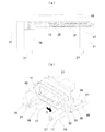
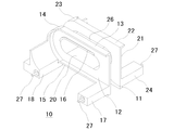
以下に、本発明の第1の実施の形態に係るトランスについて、第1の実施の形態に係る二次巻線のボビンへの装着方法について説明する。図1は、本発明の第1の実施の形態に係る二次巻線の装着方法を示し、(a)は斜視図、(b)はA−A線断面図である。また、図2は、本発明の第1の実施の形態に係る二次巻線の装着過程を示し、(a)はA−A線断面図であり、(b)は斜視図である。図1及び図2において、10はボビン、11は第1巻枠部、12は巻線装着面、13は上部リブ、14は先端側リブ、15は下部リブ、16は抜止リブ、17は基端側端子台、18は先端側端子台、20は中空部、21は第2巻枠部、24は基端側端子台、26は巻胴部、27は端子、30は二次巻線、31は1ターン目の巻線部、32は外部接続部、34は上部、35は先端部、36は下部、39は連結部、40は内周面、42は2ターン目の巻線部、48は外部接続部、49はコアである。
[First Embodiment]
Hereinafter, a method for mounting the secondary winding on the bobbin according to the first embodiment of the transformer according to the first embodiment of the present invention will be described. 1A and 1B show a mounting method of a secondary winding according to a first embodiment of the present invention, where FIG. 1A is a perspective view and FIG. 1B is a cross-sectional view taken along line AA. FIGS. 2A and 2B show a mounting process of the secondary winding according to the first embodiment of the present invention, where FIG. 2A is a cross-sectional view taken along the line AA, and FIG. 2B is a perspective view. In FIGS. 1 and 2, 10 is a bobbin, 11 is a first winding frame portion, 12 is a winding mounting surface, 13 is an upper rib, 14 is a leading rib, 15 is a lower rib, 16 is a retaining rib, and 17 is a base. End side terminal block, 18 is a front end side terminal block, 20 is a hollow portion, 21 is a second winding frame portion, 24 is a base end side terminal block, 26 is a winding body portion, 27 is a terminal, 30 is a secondary winding, 31 is a winding part of the first turn, 32 is an external connection part, 34 is an upper part, 35 is a tip part, 36 is a lower part, 39 is a connecting part, 40 is an inner peripheral surface, 42 is a winding part of the second turn, 48 is an external connection part, 49 is a core.
この実施の形態に係るボビン10は、図示しない一次巻線を巻回する筒状の巻胴部26に対して直行する方向に、二次巻線を装着する第1巻枠部11及び第2巻枠部21を設け、これらの巻枠部の下部にそれぞれ基端側端子台17及び先端側端子台18、基端側端子台24及び先端側端子台25を設けた基本構成としている。また、第1巻枠部11には、巻線装着面12が設けられており、二次巻線30を装着したときに1ターン目の巻線部31が圧接する面となる。さらに、第1巻枠部11には、抜止リブ16を設けている。なお、第2巻枠部21は、抜止リブ16に相当するものを設けていないが、他の部分の構成は第1巻枠部11と同じである。また、二次巻線30は、1ターン目の巻線部31及び2ターン目の巻線部42を第1巻枠部11と第2巻枠部21との間に挟み入れるように動かして、つまり図1(a)の矢印B方向に動かして装着する。また、1ターン目の巻線部31と2ターン目の巻線部42とは平行に設けられ、かつ、これらの距離は第1巻枠部11及び第2巻枠部21の巻線装着面間の距離にほぼ等しい。
The
抜止リブ16は、二次巻線30をボビン10に装着した後に、二次巻線30が外力によって図2(b)の矢印Cの方向に動いて脱落することを防ぐものである。また、巻線装着面12は、その中央に巻胴部26の中空部20が開口しているが、抜止リブ16はこの開口の周囲に環状に設けられている。さらに、図1(b)に示すように、抜止リブ16は基端側端子台17側から先端側端子台18側に向かって巻線装着面12から漸次突出するように形成されている。また、1ターン目の巻線部31の縁辺に設けた先端側リブ14と抜止リブ16とは1ターン目の巻線部31との距離は、1ターン目の巻線部31の幅よりもわずかに大きいものとしている。
The retaining
これらの構成によって、1ターン目の巻線部31及び2ターン目の巻線部42を第1巻枠部11と第2巻枠部21との間に挟み入れて行くと、図2(a)に示すように、抜止リブ16は1ターン目の巻線部31の先端部35を押し上げるように、つまり1ターン目の巻線部31と2ターン目の巻線部42との先端側がわずかに開くように作用する。さらに挟み入れて行くと、1ターン目の巻線部31が抜止リブ16を乗り越えて、先端側リブ14と抜止リブ16との間に嵌り込んで図2(b)に示す状態となる。この状態では、1ターン目の巻線部31中央の空隙が環状の抜止リブ16に嵌り込んでいるので、二次巻線30に対して矢印Cの方向への押圧力が加わっても、第1巻枠部11の内周面40が抜止リブ16に当接してその動きが規制される。
With these configurations, when the winding
以上のようにこの実施の形態では、二次巻線30をボビン10に装着するときに、1ターン目の巻線部31と2ターン目の巻線部42とを作業者の手又は工具で開かなくても、1ターン目の巻線部31と2ターン目の巻線部42との先端側がわずかに開いて行くので、二次巻線30を簡単に装着できる。また、二次巻線30がボビン10を挟み込んでいる上に、二次巻線30の脱落防止用に抜止リブ16を設けているので、二次巻線30の装着後は、外力によって二次巻線30が簡単に脱落することがない。
As described above, in this embodiment, when the secondary winding 30 is mounted on the
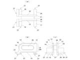
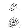
さらに、各部の詳細について説明する。図3は、本発明の第1の実施の形態に係るボビンを示す斜視図である。また、図4は、本発明の第1の実施の形態に係るボビンを示し、(a)は平面図、(b)は正面図、(c)は側面図である。図3及び図4において、19は開口部、22は上部リブ、23は先端側リブ、25は先端側端子台、28は巻線装着面、29は開口部である。 Further, details of each part will be described. FIG. 3 is a perspective view showing the bobbin according to the first embodiment of the present invention. FIG. 4 shows the bobbin according to the first embodiment of the present invention, wherein (a) is a plan view, (b) is a front view, and (c) is a side view. 3 and 4, 19 is an opening, 22 is an upper rib, 23 is a tip-side rib, 25 is a tip-side terminal block, 28 is a winding mounting surface, and 29 is an opening.
ボビン10は、端子27を除いて樹脂等の絶縁性のある材料で形成されている。また、一次巻線を巻回する筒状の巻胴部26に対して直行する方向に、二次巻線を装着する第1巻枠部11及び第2巻枠部21を設け、これらの巻枠部の下部にそれぞれ基端側端子台17及び先端側端子台18、基端側端子台24及び先端側端子台25を設けた基本構成としている。
The
第1巻枠部11は、巻胴部26の端部付近に、巻胴部26の鍔のような形状で設けられており、巻線装着面12に帯状導体から形成した巻線の1ターン目を装着する。また、第1巻枠部11の縁辺の上部、先端部及び下部には、それぞれ上部リブ13、先端側リブ14及び下部リブ15を設けている。また、巻胴部26の端部は、巻線装着面12から突出しており、この突出した部分が抜止リブ16となっている。第1巻枠部11の基端側は、リブを形成せずに、巻線を挿入するための開口部19としている。すなわち、巻線装着面12に巻線を装着する際に、第1巻枠部11の基端側にリブがなければ基端側から巻線を挿入することが容易にできるので、基端側にはリブを設けていない。また、巻線装着面12と巻線装着面28との間の距離は、1ターン目の巻線部31と2ターン目の巻線部42との距離に等しい。
The first winding
上部リブ13及び下部リブ15は、巻線装着面12の縁辺から垂直に立ち上がるように形成しており、開口部19から挿入された巻線を案内する。先端側リブ14は、第1巻枠部11の基端側から挿入された巻線の動きを規制する。また、抜止リブ16は、先に述べたように、1ターン目の巻線部31が抜止リブ16を乗り越えて先端側リブ14と抜止リブ16との間に嵌り込んだときに、1ターン目の巻線部31中央の空隙が環状の抜止リブ16に嵌り込むように設けられている。なお、この実施の形態では、ボビン10の成形を容易にするために、先端側リブ14の一部が先端側端子台25と、下部リブ15の一部が基端側端子台24と一体化しているが、これらを分離しても良い。また、抜止リブ16は、最も突出した部分の高さを約1mmとしているが、この高さは巻線の大きさ、材質等に応じて適宜変更でき、特に1mmという高さに限られるものではない。
The
基端側端子台17は、第1巻枠部11の下部の基端側部分と一体的に形成されている。同様に、先端側端子台18は、第1巻枠部11の下部の先端側部分と一体的に形成されている。また、基端側端子台17及び先端側端子台18の先端面、及び、第1巻枠部11寄りの下面の計4カ所に端子27が設けられている。なお、この実施の形態では、基端側端子台17及び先端側端子台18を第1巻枠部11から巻胴部26と平行に延びるような形状としているが、これらの形状は実装する基板等に応じて適宜変更でき、図3及び図4の形状に限られるものではない。また、端子27を設ける個数も設計条件等に応じて適宜選択できる。
The base end
第2巻枠部21は、第1巻枠部11と平行に、かつ、第1巻枠部21と巻胴部26の端部付近に、巻胴部26の鍔のような形状で設けられている。また、第1巻枠部11と同様に、その縁辺の上部、先端部及び下部に、それぞれ上部リブ22、先端側リブ23及び下部リブ28を設けている。第2巻枠部21の基端側は、リブを形成せずに、帯状導体から形成した巻線の2ターン目を挿入するための開口部29としている。
The second winding
なお、この実施の形態では、二次巻線30をあまり変形させなくてもボビンに装着できるようにするために、第2巻枠部21に抜止リブを設けていない。もちろん、第2巻枠部21にも抜止リブ16と同様のリブを設けることは可能であり、このようにすれば巻線をより確実に保持することができる。また、この実施の形態では、抜止リブは第1巻枠部11と第2巻枠部21とのいずれかに設けてあれば良く、第1巻枠部11に特に限定されない。
In this embodiment, the second winding
巻胴部26は、中空部20を設けて内部に図1に示したコア49が挿入されるようにしており、導体線条から形成された(図示していない)一次巻線が巻回される。また、中空部20は、第1巻枠部11及び第2巻枠部21の中央の開口となっている。したがって、この実施の形態では、一次巻線が二次巻線の1ターン目と2ターン目の間に設けられている構造となる。また、一次巻線と二次巻線とを隔てる距離は、第1巻枠部11又は第2巻枠部21の厚みだけとなる。なお、この実施の形態においては、一次巻線は導体線条のものであれば良く、材質等は特に問わない。さらに、前述したように、第1巻枠部11側の端部が抜止リブ16となっている。また、コア49は、以上の構成が成り立つものであれば、どのような形状又は材質であっても良い。
The winding
また、この実施の形態はトランスに関するものであるが、巻胴部26に巻線を巻回せずにそのまま利用すれば、チョークコイルとして好ましく用いることができる。
Although this embodiment relates to a transformer, if it is used as it is without winding a winding around the winding
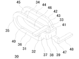
次に、二次巻線について説明する。図5は、本発明の第1の実施の形態に係る二次巻線を示す斜視図である。また、図6は、本発明の第1の実施の形態に係る二次巻線を示し、(a)は平面図、(b)は正面図、(c)は側面図である。図5及び図6において、30は二次巻線、31は1ターン目の巻線部、32は外部接続部、33は折曲部、34は上部、35は先端部、36は下部、37は基端部、38は折曲部、39は連結部、40は内周面、41は折曲部、42は2ターン目の巻線部、43は基端部、44は上部、45は先端部、46は下部、47は折曲部、48は外部接続部である。 Next, the secondary winding will be described. FIG. 5 is a perspective view showing the secondary winding according to the first embodiment of the present invention. FIG. 6 shows the secondary winding according to the first embodiment of the present invention, in which (a) is a plan view, (b) is a front view, and (c) is a side view. 5 and 6, 30 is a secondary winding, 31 is a winding part of the first turn, 32 is an external connection part, 33 is a bent part, 34 is an upper part, 35 is a tip part, 36 is a lower part, 37 Is a base part, 38 is a bent part, 39 is a connecting part, 40 is an inner peripheral surface, 41 is a bent part, 42 is a winding part for the second turn, 43 is a base part, 44 is an upper part, 45 is A tip part, 46 is a lower part, 47 is a bent part, and 48 is an external connection part.
二次巻線30は、銅合金等の導電性の高い金属で形成されている。また、2ターンの巻線であり、1ターン目の巻線部31と2ターン目の巻線部42とを連結部39を介して一体化している。また、1ターン目の巻線部31と2ターン目の巻線部42とは、平行になるように形成されている。また、先の述べたようにこれらの距離は巻線装着面12と巻線装着面28との間の距離に等しいので、二次巻線30をボビン10に装着した状態において、1ターン目の巻線部31と2ターン目の巻線部42とが巻線装着面12と巻線装着面28とを挟んで自己保持する。さらに、これらの間隔は、第1巻枠部11及び第2巻枠部21の巻線装着面の間隔に合わせて設定されている。すなわち、二次巻線30の1ターン目の巻線部31と2ターン目の巻線部42とが、ボビン10の1巻枠部11と第2巻枠部21とを外側から挟み込めるようにしている。なお、以上の構成は、1枚の金属板にプレス加工等を施すことによって実現している。
The secondary winding 30 is made of a highly conductive metal such as a copper alloy. In addition, the winding is a two-turn winding, and the winding
また、二次巻線30の始まりの部分には、外部接続部32を水平方向に延びるように設け、隣り合う二次巻線等との接続を容易にしている。外部接続部32からは、折曲部33を介して1ターン目の巻線部31の上部34、先端部35、下部36、基端部37と続いており、さらに基端部37から折曲部38を介して連結部39に連続している。くわえて、連結部39から折曲部41を介して2ターン目の巻線部42の基端部43、上部44、先端部45、下部46と続き、さらに折曲部47を介して外部接続部48へ続いている。なお、外部接続部32、48は、隣り合う二次巻線等の外部にある回路要素への接続を容易にするために設けている。また、この実施例は、2ターンの二次巻線を持つトランスであるが、ボビン10及び二次巻線30の組み合わせを連続的に配置し、外部接続部同士を半田付け等で繋ぎ合わせれば、4ターン、6ターン、8ターン、10ターンなどより多くの偶数の巻数を持つトランスが得られる。
Further, an
また、1ターン目の巻線部31の上部34、先端部35、下部36及び基端部37の内周面40は、二次巻線30をボビン10に装着したときに、抜止リブ16の外周面が収まる大きさ及び形状に形成されている。すなわち、二次巻線30をボビン10に装着すると、1ターン目の巻線部31の上部34、先端部35、下部36及び基端部37で囲まれた中に抜止リブ16が嵌り込むので、トランスの組立工程などにおいて二次巻線30がボビン10から脱落することを防止できる。
Further, the inner
以上のように、第1の実施の形態に係るトランスにおいては、1ターン目の巻線部31及び2ターン目の巻線部42を第1巻枠部11と第2巻枠部21との間に挟み入れて行くことによって二次巻線30を簡単に装着できる。また、二次巻線30をボビン10に装着すると、抜止リブ16が第1巻枠部11の動きを規制するので、外部から加わる力によって二次巻線30が簡単に脱落することがない。さらに、二次巻線30の脱落を防止するための固着作業が不要になるので作業負担が軽くなる。
As described above, in the transformer according to the first embodiment, the winding
なお、図1などに示した構成は、本発明の一つの実施の形態であり、これらの図に示した形状等に限定されるものではない。例えば、一次巻線が帯状導体である場合には、一次巻線に二次巻線30の構成を適用しても良い。また、抜止リブ16をテーパ面とするのではなく、凹面状又は凸面状の曲面状に形成しても良い。さらに、ボビン10をチョークコイルとして利用する場合には、第1巻枠部11との第2巻枠部21との間隔を適宜調整できる。
The configuration shown in FIG. 1 and the like is one embodiment of the present invention and is not limited to the shape shown in these drawings. For example, when the primary winding is a strip-shaped conductor, the configuration of the secondary winding 30 may be applied to the primary winding. Further, the retaining
[第2の実施の形態]
以下に、本発明の第2の実施の形態に係るトランスを図面に基づいて詳細に説明する。図7は、本発明の第2の実施の形態に係るボビンを示す斜視図である。図7の符号は、図3及び図4と同じである。
[Second Embodiment]
Hereinafter, a transformer according to a second embodiment of the present invention will be described in detail with reference to the drawings. FIG. 7 is a perspective view showing a bobbin according to the second embodiment of the present invention. The reference numerals in FIG. 7 are the same as those in FIGS.
この実施の形態に係るボビン10では、抜止リブ16を中空部20の開口の周囲に環状に設けるのではなく、上部リブ13及び先端側リブ14の近傍にのみ設けている。したがって、1ターン目の巻線部31及び2ターン目の巻線部42を第1巻枠部11と第2巻枠部21との間に挟み入れるときに、1ターン目の巻線部31及び2ターン目の巻線部42の下側はあまり開かない構成となっている。よって、この実施の形態は二次巻線30の剛性が大きく、1ターン目の巻線部31と2ターン目の巻線部42とが開きにくい場合に好ましく適用できる。なお、抜止リブ16を形成する位置は、1ターン目の巻線部31の形状に応じて適宜変更することが可能である。例えば中空部20の開口から離れた位置など、1ターン目の巻線部31に囲まれる部位であればどこに形成しても良い。
In the
[第3の実施の形態]
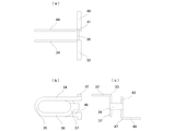
以下に、本発明の第3の実施の形態に係るトランスを図面に基づいて詳細に説明する。図8は、本発明の第3実施の形態に係る二次巻線の装着方法を示す斜視図である。図8において50は挟持部、51は連結部であり、その他の符号は図1と同じである。
[Third Embodiment]
Hereinafter, a transformer according to a third embodiment of the present invention will be described in detail with reference to the drawings. FIG. 8 is a perspective view showing a secondary winding mounting method according to the third embodiment of the present invention. In FIG. 8, 50 is a clamping part, 51 is a connection part, The other code | symbol is the same as FIG.
この実施の形態に係るトランスの二次巻線30は、1ターンの巻線が図1の1ターン目の巻線部31に相当するものがあるが、図1の2ターン目の巻線部42に相当するものはない。また、2ターン目の巻線部42に代えて、挟持部50を設けている。挟持部50は、2ターン目の巻線部42の基端部43に相当する部位に設けている。さらに、挟持部50は、二次巻線30を矢印B方向に動かして装着したときに、第2巻枠部21に当接し、1ターン目の巻線部31と共にボビン10を外側から挟み込んだ状態となる。連結部51は、一端が挟持部50に連続しており、他端が外部接続部48と連続している。したがって、挟持部50及び連結部51は、巻線として機能する部分ではなく、二次巻線30の装着や、外部装置との電気的接続を確保するためのものである。なお、ボビン10は、図1に示したものと全く同じ構成である。
As for the secondary winding 30 of the transformer according to this embodiment, one turn of the winding corresponds to the first turn of the winding 31 of FIG. 1, but the second turn of FIG. There is no equivalent to 42. Further, a pinching
以上のように、本発明は、トランスの二次巻線が1ターンのみである場合にも好ましく適用できる。また、この実施の形態では、二次巻線30に挟持部50を設けているので、図1に示したボビン10をそのまま利用できる、つまり1ターン及び2ターンのトランスに対して同じボビンを共用できるという利点がある。
As described above, the present invention can be preferably applied to the case where the secondary winding of the transformer has only one turn. Further, in this embodiment, since the holding
[第4の実施の形態]
以下に、本発明の第3の実施の形態に係るトランスを図面に基づいて詳細に説明する。図9は、本発明の第4実施の形態に係る二次巻線の装着方法を示す斜視図である。図9の符号は図8と同じものを示す。
[Fourth Embodiment]
Hereinafter, a transformer according to a third embodiment of the present invention will be described in detail with reference to the drawings. FIG. 9 is a perspective view showing a secondary winding mounting method according to the fourth embodiment of the present invention. The reference numerals in FIG. 9 denote the same elements as in FIG.
この実施の形態は、第3の実施の形態とほぼ同じ構成であるが、外部接続部48の先端部が外部接続部32の先端部と同じ向きになるようにした点が他の実施の形態と異なる。したがって、この実施の形態は、外部装置との電気的接続を確保する上で、二次巻線の2本の端部を同じ方向に揃える必要がある場合に好適である。なお、挟持部50に代えて樹脂製の挟持部を設け、連結部39と外部接続部48との間の構成をさらに単純なものとすることも可能である。また、2ターン目の巻線部42と同形状の樹脂製の挟持部を設けても良い。なお、樹脂製の挟持部は、二次巻線30に対して接着することによって一体化できるが、溶着など他の方法によっても良い。さらに、挟持部に設けた孔に二次巻線30を挿入し、さらにこの孔に接着剤を流し込んで挟持部と二次巻線30との接触部近傍を接着するなどの方法も好ましく適用できる。
This embodiment has substantially the same configuration as the third embodiment, but the other embodiment is that the tip of the
本発明は以上に説明した内容に限定されるものではなく、ボビン、二次巻線の形状や構造については、各請求項に記載した範囲を逸脱しない限りにおいて種々の変形を加えることが可能である。また、各実施の形態に係るトランスについて述べた各部の変形例は、他の実施の形態に係るトランスにおいても、構造的な矛盾を生じない限りにおいて好ましく適用できる。また、これらの実施の形態は、一次巻線を設けなければチョークコイルとしてそのまま利用できる。 The present invention is not limited to the contents described above, and various modifications can be made to the shape and structure of the bobbin and the secondary winding without departing from the scope described in each claim. is there. In addition, the modified examples of the respective parts described for the transformer according to each embodiment can be preferably applied to the transformers according to other embodiments as long as no structural contradiction occurs. Further, these embodiments can be used as they are as a choke coil if a primary winding is not provided.
10 ボビン
11 第1巻枠部
12 巻線装着面
13 上部リブ
14 先端側リブ
15 下部リブ
16 抜止リブ
17 基端側端子台
18 先端側端子台
19 開口部
20 中空部
21 第2巻枠部
22 上部リブ
23 先端側リブ
24 基端側端子台
25 先端側端子台
26 巻胴部
27 端子
28 巻線装着面
29 開口部
30 二次巻線
31 1ターン目の巻線部
32 外部接続部
33 折曲部
34 上部
35 先端部
36 下部
37 基端部
38 折曲部
39 連結部
40 内周面
41 折曲部
42 2ターン目の巻線部
43 基端部
44 上部
45 先端部
46 下部
47 折曲部
48 外部接続部
49 コア
50 挟持部
51 連結部
60 ボビン
61 一次巻線
62 端子
63 巻枠
DESCRIPTION OF
Claims (5)
前記巻線は、1ターンの第1巻線部と、前記第1巻線部と平行に配置してある1ターンの第2巻線部と、前記第1巻線部の端部と前記第2巻線部の端部とを接続する連結部とを備えると共に、前記第1巻線部と前記第2巻線部との間に前記ボビンを挟み入れることによって装着され、
前記ボビンは、前記巻線を装着した状態において前記第1巻線部と前記第2巻線部とにそれぞれ圧接している第1装着面と第2装着面とを備えると共に、第1装着面との第2装着面との少なくとも一方は、前記第1巻線部又は前記第2巻線部に囲まれている部位に前記連結部が位置する側から離れるに従って漸次突出する前記巻線の抜止部を形成してあることを特徴とするチョークコイル。 In the choke coil provided with a winding formed from a strip-shaped conductor and a bobbin on which the winding is mounted,
The winding includes a first winding portion of one turn, a second winding portion of one turn arranged in parallel with the first winding portion, an end portion of the first winding portion, and the first winding portion. And a connecting portion that connects the ends of the two winding portions, and is mounted by sandwiching the bobbin between the first winding portion and the second winding portion,
The bobbin includes a first mounting surface and a second mounting surface that are in pressure contact with the first winding portion and the second winding portion, respectively, in a state where the winding is mounted. At least one of the second mounting surface and the second mounting surface is a retaining portion of the winding that gradually protrudes from the side where the connecting portion is located at a portion surrounded by the first winding portion or the second winding portion. A choke coil having a portion formed therein.
前記巻線は、1ターンの巻線部と、前記巻線部と対向してある挟持部と、前記巻線部の端部と前記挟持部の端部とを接続する連結部とを備えると共に、前記巻線部と前記挟持部との間に前記ボビンを挟み入れることによって装着され、
前記ボビンは、前記巻線を装着した状態において前記巻線部と前記挟持部とにそれぞれ圧接している第1装着面と第2装着面とを備えると共に、第1装着面は、前記巻線部に囲まれている部位に前記連結部が位置する側から離れるに従って漸次突出する前記巻線の抜止部を形成してあることを特徴とするチョークコイル。 In the choke coil provided with a winding formed from a strip-shaped conductor and a bobbin on which the winding is mounted,
The winding includes a winding part of one turn, a sandwiching part facing the winding part, and a connecting part that connects an end of the winding part and an end of the sandwiching part. The bobbin is inserted between the winding portion and the clamping portion;
The bobbin includes a first mounting surface and a second mounting surface that are in pressure contact with the winding portion and the sandwiching portion in a state where the winding is mounted, and the first mounting surface includes the winding A choke coil characterized in that a retaining portion of the winding that gradually protrudes as the distance from the side where the connecting portion is located is formed at a portion surrounded by the portion.
前記巻線は、1ターンの第1巻線部と、前記第1巻線部と平行に配置してある1ターンの第2巻線部と、前記第1巻線部の端部と前記第2巻線部の端部とを接続する連結部とを備えると共に、前記第1巻線部と前記第2巻線部との間に前記ボビンを挟み入れることによって装着され、
前記ボビンは、前記巻線を装着した状態において前記第1巻線部と前記第2巻線部とにそれぞれ圧接している第1装着面と第2装着面とを備えると共に、第1装着面との第2装着面との少なくとも一方は、前記第1巻線部又は前記第2巻線部に囲まれている部位に前記連結部が位置する側から離れるに従って漸次突出する前記巻線の抜止部を形成してあることを特徴とするトランス。 In a transformer including a winding formed from a strip-shaped conductor and a bobbin on which the winding is mounted,
The winding includes a first winding portion of one turn, a second winding portion of one turn arranged in parallel with the first winding portion, an end portion of the first winding portion, and the first winding portion. And a connecting portion that connects the ends of the two winding portions, and is mounted by sandwiching the bobbin between the first winding portion and the second winding portion,
The bobbin includes a first mounting surface and a second mounting surface that are in pressure contact with the first winding portion and the second winding portion, respectively, in a state where the winding is mounted. At least one of the second mounting surface and the second mounting surface is a retaining portion of the winding that gradually protrudes from the side where the connecting portion is located at a portion surrounded by the first winding portion or the second winding portion. Transformer characterized by forming part.
前記巻線は、1ターンの巻線部と、前記巻線部と対向してある挟持部と、前記巻線部の端部と前記挟持部の端部とを接続する連結部とを備えると共に、前記巻線部と前記挟持部との間に前記ボビンを挟み入れることによって装着され、
前記ボビンは、前記巻線を装着した状態において前記巻線部と前記挟持部とにそれぞれ圧接している第1装着面と第2装着面とを備えると共に、第1装着面は、前記巻線部に囲まれている部位に前記連結部が位置する側から離れるに従って漸次突出する前記巻線の抜止部を形成してあることを特徴とするトランス。 In a transformer including a winding formed from a strip-shaped conductor and a bobbin on which the winding is mounted,
The winding includes a winding part of one turn, a sandwiching part facing the winding part, and a connecting part that connects an end of the winding part and an end of the sandwiching part. The bobbin is inserted between the winding portion and the clamping portion;
The bobbin includes a first mounting surface and a second mounting surface that are in pressure contact with the winding portion and the sandwiching portion in a state where the winding is mounted, and the first mounting surface includes the winding The transformer is characterized in that a part of the winding that protrudes gradually as the distance from the side where the connecting part is located is formed in a part surrounded by the part.
Priority Applications (1)
| Application Number | Priority Date | Filing Date | Title |
|---|---|---|---|
| JP2008259935A JP5355982B2 (en) | 2008-10-06 | 2008-10-06 | Choke coil and transformer |
Applications Claiming Priority (1)
| Application Number | Priority Date | Filing Date | Title |
|---|---|---|---|
| JP2008259935A JP5355982B2 (en) | 2008-10-06 | 2008-10-06 | Choke coil and transformer |
Publications (2)
| Publication Number | Publication Date |
|---|---|
| JP2010092986A true JP2010092986A (en) | 2010-04-22 |
| JP5355982B2 JP5355982B2 (en) | 2013-11-27 |
Family
ID=42255445
Family Applications (1)
| Application Number | Title | Priority Date | Filing Date |
|---|---|---|---|
| JP2008259935A Active JP5355982B2 (en) | 2008-10-06 | 2008-10-06 | Choke coil and transformer |
Country Status (1)
| Country | Link |
|---|---|
| JP (1) | JP5355982B2 (en) |
Citations (9)
| Publication number | Priority date | Publication date | Assignee | Title |
|---|---|---|---|---|
| JPS59185811U (en) * | 1983-05-25 | 1984-12-10 | ティーディーケイ株式会社 | high voltage transformer |
| JPH0270412U (en) * | 1988-11-18 | 1990-05-29 | ||
| JPH03283505A (en) * | 1990-03-30 | 1991-12-13 | Multisource Technol Corp | Transformer composite |
| JPH0682838U (en) * | 1993-05-10 | 1994-11-25 | 池田電機株式会社 | Leakage type electromagnetic device |
| JP2000223320A (en) * | 1999-01-28 | 2000-08-11 | Hitachi Ferrite Electronics Ltd | Transformer for large current |
| JP2002280225A (en) * | 2001-03-22 | 2002-09-27 | Origin Electric Co Ltd | Flat coil, its manufacturing method and transformer simple flat coil |
| JP2003124040A (en) * | 2001-10-19 | 2003-04-25 | Nec Tokin Corp | Choke coil and its manufacturing method |
| US7091817B2 (en) * | 2001-09-28 | 2006-08-15 | Delta Energy Systems (Switzerland) Ag | Planar transformer comprising plug-in secondary windings |
| JP3139944U (en) * | 2007-12-26 | 2008-03-06 | 冠徳科技(深▲ぜん▼)有限公司 | Transformer |
-
2008
- 2008-10-06 JP JP2008259935A patent/JP5355982B2/en active Active
Patent Citations (9)
| Publication number | Priority date | Publication date | Assignee | Title |
|---|---|---|---|---|
| JPS59185811U (en) * | 1983-05-25 | 1984-12-10 | ティーディーケイ株式会社 | high voltage transformer |
| JPH0270412U (en) * | 1988-11-18 | 1990-05-29 | ||
| JPH03283505A (en) * | 1990-03-30 | 1991-12-13 | Multisource Technol Corp | Transformer composite |
| JPH0682838U (en) * | 1993-05-10 | 1994-11-25 | 池田電機株式会社 | Leakage type electromagnetic device |
| JP2000223320A (en) * | 1999-01-28 | 2000-08-11 | Hitachi Ferrite Electronics Ltd | Transformer for large current |
| JP2002280225A (en) * | 2001-03-22 | 2002-09-27 | Origin Electric Co Ltd | Flat coil, its manufacturing method and transformer simple flat coil |
| US7091817B2 (en) * | 2001-09-28 | 2006-08-15 | Delta Energy Systems (Switzerland) Ag | Planar transformer comprising plug-in secondary windings |
| JP2003124040A (en) * | 2001-10-19 | 2003-04-25 | Nec Tokin Corp | Choke coil and its manufacturing method |
| JP3139944U (en) * | 2007-12-26 | 2008-03-06 | 冠徳科技(深▲ぜん▼)有限公司 | Transformer |
Also Published As
| Publication number | Publication date |
|---|---|
| JP5355982B2 (en) | 2013-11-27 |
Similar Documents
| Publication | Publication Date | Title |
|---|---|---|
| CN1949415B (en) | Coiling sheet stype common mode choking coil | |
| JP5786660B2 (en) | Magnetic component and method of manufacturing magnetic component | |
| JP5215761B2 (en) | Trance | |
| US20110115594A1 (en) | Magnetic element, fabricating process thereof, and assembly of magnetic element and circuit carrier | |
| KR101388797B1 (en) | Coil component, mounting structure thereof, and electronic device having the same | |
| JP2002043136A (en) | Reactor | |
| JP2007157956A (en) | Switching transformer | |
| JP2009105342A (en) | Lateral coil component, bobbin, and method of connecting and fixing end of wire | |
| EP2779185B1 (en) | Improved structure of transformer's lead frame | |
| JP5355982B2 (en) | Choke coil and transformer | |
| JP4837485B2 (en) | Inductor and method of manufacturing inductor | |
| JP4584040B2 (en) | Coil terminal | |
| JP2001035730A (en) | High-frequency transformer | |
| JP4892961B2 (en) | Coil parts | |
| EP2919251B1 (en) | Coil terminal and electromagnetic relay | |
| JP5429958B2 (en) | Choke coil, transformer, and method of manufacturing winding | |
| JP2010062279A (en) | Shell type amorphous transformer | |
| JPH03129712A (en) | Transformer coil | |
| JP2005251933A (en) | Wound coil component | |
| JP2012216579A (en) | Bobbin | |
| JP4987657B2 (en) | Small step-up transformer | |
| JP5093893B2 (en) | choke coil | |
| JP5217824B2 (en) | Winding parts | |
| KR102311192B1 (en) | Coil winding tape | |
| JP5417559B2 (en) | Small step-up transformer |
Legal Events
| Date | Code | Title | Description |
|---|---|---|---|
| A621 | Written request for application examination |
Free format text: JAPANESE INTERMEDIATE CODE: A621 Effective date: 20110614 |
|
| A977 | Report on retrieval |
Free format text: JAPANESE INTERMEDIATE CODE: A971007 Effective date: 20121012 |
|
| A131 | Notification of reasons for refusal |
Free format text: JAPANESE INTERMEDIATE CODE: A131 Effective date: 20121017 |
|
| A521 | Written amendment |
Free format text: JAPANESE INTERMEDIATE CODE: A523 Effective date: 20121206 |
|
| TRDD | Decision of grant or rejection written | ||
| A01 | Written decision to grant a patent or to grant a registration (utility model) |
Free format text: JAPANESE INTERMEDIATE CODE: A01 Effective date: 20130718 |
|
| A61 | First payment of annual fees (during grant procedure) |
Free format text: JAPANESE INTERMEDIATE CODE: A61 Effective date: 20130828 |
|
| R150 | Certificate of patent or registration of utility model |
Ref document number: 5355982 Country of ref document: JP Free format text: JAPANESE INTERMEDIATE CODE: R150 Free format text: JAPANESE INTERMEDIATE CODE: R150 |