JP4584040B2 - Coil terminal - Google Patents
Coil terminal Download PDFInfo
- Publication number
- JP4584040B2 JP4584040B2 JP2005170326A JP2005170326A JP4584040B2 JP 4584040 B2 JP4584040 B2 JP 4584040B2 JP 2005170326 A JP2005170326 A JP 2005170326A JP 2005170326 A JP2005170326 A JP 2005170326A JP 4584040 B2 JP4584040 B2 JP 4584040B2
- Authority
- JP
- Japan
- Prior art keywords
- terminal
- upper plate
- coil
- bent
- slit
- Prior art date
- Legal status (The legal status is an assumption and is not a legal conclusion. Google has not performed a legal analysis and makes no representation as to the accuracy of the status listed.)
- Expired - Fee Related
Links
Images


Landscapes
- Coils Of Transformers For General Uses (AREA)
- Coils Or Transformers For Communication (AREA)
Description
この発明は、コイルの引出線を接続するコイル用端子に関する。 The present invention relates to a coil terminal for connecting a lead wire of a coil.
従来、コイルの引出線を端子に接続する場合、一般的には特開平6−283361号公報に示されるように、引出線を端子に絡げ付け、半田付けしている。 Conventionally, when connecting a lead wire of a coil to a terminal, the lead wire is generally tangled to the terminal and soldered as disclosed in Japanese Patent Laid-Open No. 6-283361.
トロイダルコイルの引出線の処理も通常同様に行われている。
従来では引出線を端子に接続する場合、絡げ付けの工数を有する。 Conventionally, when connecting a lead wire to a terminal, it has a man-hour for binding.
また、大電流が通電されるコイルでは電線として太い丸線が使用され、このような太い電線は腰が強いために絡げ付けの作業が厄介である。さらに、多本巻きのトロイダルコイルでは各内部巻線の引出線をそれぞれ絡げ付けるのは、本数が多いため、それだけ時間と手間がかかり、作業性が悪い、という課題があった。 In addition, a thick round wire is used as a wire in a coil that is energized with a large current. Since such a thick wire is stiff, it is difficult to bind the wires. Furthermore, in the multi-winding toroidal coil, there are many problems in that the lead wires of the respective internal windings are entangled, so that it takes a lot of time and effort and the workability is poor.
この発明は上記のことに鑑み提案されたもので、その目的とするところは、絡げ付けの工数を不要とし、コイルの引出線を容易、かつ迅速、確実に接続でき、特にトロイダルコイルの表面実装用端子として用いると好適なコイル用端子を提供することにある。 The present invention has been proposed in view of the above, and the object of the present invention is to eliminate the need for tangling, and to easily and quickly connect the lead wire of the coil, and particularly the surface of the toroidal coil. An object of the present invention is to provide a coil terminal suitable for use as a mounting terminal.
請求項1記載の発明は、コイルの引出線が接続される端子において、この端子は、引出線を収納する複数のスリットが形成され、かつケースに取り付けられる上板と、この上板外端部を下方に折曲形成してなる側板とを備え、前記側板部分であってスリットの外端部に外側に向って延び、かつ折曲可能な帯状の切り起こし片が形成され、この端子部をほぼL字状に折曲し面実装用端子とすることを特徴とする。
請求項2記載の発明は、請求項1記載のコイル用端子において、前記上板の一端部に、前記スリット側に折曲可能な突起部を形成したことを特徴とする。
請求項3記載の発明は、コイルの引出線が接続される端子において、この端子は、引出線を収納する複数のスリットが形成され、かつケースに取り付けられる上板を有し、この上板の外端部において下方に向かって延びる側板が連結され、かつ前記側板の下方中央部を内側に向かって切り起こして下板とするとともに、下方に向って延びる前記側板の両端部を端子部とし、この端子部をディスクリート用端子またはほぼL字状に折曲して面実装用端子とするを特徴とする。
請求項4記載の発明は、請求項3記載のコイル用端子において、前記上板の一端部に、前記スリット側に向って折曲可能な突起部を形成したことを特徴とする。
According to the first aspect of the present invention, in the terminal to which the lead wire of the coil is connected, the terminal is formed with a plurality of slits for accommodating the lead wire and is attached to the case, and the outer end portion of the upper plate A side plate formed by bending downward, and a strip-like cut-and-raised piece is formed on the side plate portion, extending outward at the outer end of the slit, and bendable. It is characterized in that it is bent into a substantially L shape to form a surface mounting terminal .
According to a second aspect of the present invention, in the coil terminal according to the first aspect, a protrusion that can be bent toward the slit is formed at one end of the upper plate .
According to a third aspect of the present invention, in the terminal to which the lead wire of the coil is connected, the terminal has an upper plate formed with a plurality of slits for accommodating the lead wire and attached to the case. A side plate extending downward at the outer end is connected, and a lower center portion of the side plate is cut and raised toward the inside to form a lower plate, and both end portions of the side plate extending downward are used as terminal portions, This terminal portion is characterized by being a discrete terminal or a surface mounting terminal by bending it into a substantially L shape .
The invention of
請求項1記載の発明によれば、引出線接続部に複数のスリットを形成し、そのスリット内に引出線を配線し接続するようにしたため、従前のような引出線の絡げ作業に比べ、その工数が不要となり、接続の作業性が格段に向上する。このため、引出線がトロイダルコイルの多本巻きの内部巻線のような場合であっても同時に簡単に接続することができる。また、スリットを形成するための切り起こし片を面実装用の端子として利用できる効果がある。
請求項2記載の発明によれば、突起部は折曲可能であり、折曲前は、引出線接続に邪魔にならず、接続後に折り曲げることにより、引出線を確実に接続固定することができるため、端子を基板に半田付けする際、その熱によってスリット内の引出線が外れてしまうことを防止し得る。
請求項3記載の発明によれば、側板の切り起こして折曲した部分を下板とし、上板とともに取付部への取付けに利用でき、かつ側板の両側を必要に応じディスクリート用端子または面実装用端子として選択的に使用でき汎用性を有する、といった効果がある。
請求項4記載の発明によれば、請求項3記載のコイル端子において、突起部は折曲可能であり、折曲前は、引出線接続に邪魔にならず、接続後に折り曲げることにより、引出線を確実に接続固定することができるため、端子を基板に半田付けする際、その熱によってスリット内の引出線が外れてしまうことを防止し得る。
According to the first aspect of the present invention, a plurality of slits are formed in the lead wire connecting portion, and the lead wires are wired and connected in the slit. This man-hour is not required, and the connection workability is greatly improved. For this reason, even if the lead wire is a multi-winding internal winding of a toroidal coil, it can be easily connected simultaneously. Further, there is an effect that the cut and raised piece for forming the slit can be used as a terminal for surface mounting.
According to the second aspect of the present invention, the projecting portion can be bent, and before the bending, it does not interfere with the lead wire connection, and the lead wire can be reliably connected and fixed by bending after the connection. Therefore, when the terminal is soldered to the substrate, it is possible to prevent the leader line in the slit from coming off due to the heat.
According to the third aspect of the present invention, the side plate cut and raised and bent is used as the lower plate, and can be used together with the upper plate for attachment to the mounting portion, and both sides of the side plate can be used for discrete terminals or surface mounting. There is an effect that it can be selectively used as a service terminal and has versatility.
According to a fourth aspect of the present invention, in the coil terminal according to the third aspect, the protruding portion can be bent, and before the bending, it does not interfere with the lead wire connection, and is bent after the connection, thereby leading the lead wire. Therefore, when the terminal is soldered to the substrate, it is possible to prevent the lead wire in the slit from being detached due to the heat .
以下、図面に沿って本発明の実施例を説明する。 Embodiments of the present invention will be described below with reference to the drawings.
図1は本発明の前提となる参考例1にかかる表面実装用端子の斜視図を示す。
表面実装用端子1は導電性材料からなり、ほぼ横長の矩形をなす上板2と、これと離間して下側に対向配置された下板3と、これら上板2および下板3の外端部を連結する側板4とを備え、側面から見るとほぼコ字状をなしている。上板2と下板3はその材質に起因するバネ性を有し、上板2、下板3間に台座、端子台または端子板等(図示せず)を圧入可能になっており、容易に取り付けることができる。
FIG. 1 is a perspective view of a surface mounting terminal according to Reference Example 1 which is a premise of the present invention.
The
なお、台座等への取り付けは圧入に限らず、埋め込みまたは後付けでも良い。 Note that the attachment to the pedestal or the like is not limited to press fitting, and may be embedded or retrofitted.
また、前記上板2には櫛状に複数個のスリット2aが適間隔で形成されている。このスリット2aは上板2の内端から、上板2の外端部側の側板4の上部にかけて形成されている。図示例ではスリット2aは3つ形成されているが、必ずしもその数に限定されるものでなく適宜増減し得ることは勿論である。
The
上板2の厚みaは引出線の径または引出線が平角線の場合、その厚みとほぼ同じとし、引出線をスリット2a内に収納するようにすると好ましい。大電流通電用の電線が丸線の場合、その径が大きく、太く、平角線の場合は厚みがある。上板2の厚みaをそれとほぼ同じとしておくと、その太さまたは厚みを吸収することができ好ましい。なお、必ずしも引出線の径または厚みと同じでなくとも良いことは勿論である。
The thickness a of the
また、上板2の一端部には上板2の長さ方向に延びる板状の突起部2bが折曲可能に形成されている。この突起部2bの長さbは上板2の長さcとほぼ同様にすると好ましい。
A plate-
図2(a)は、表面実装用の端子1のスリット2aにコイルの引出線5を接続した状態を示す。引出線5はスリット2a内の内端側から外端側にかけて収納・接続される。本発明では多本巻きのトロイダルコイルの内部巻線であっても同一の端子1に同時に接続することを容易にしている。そして、特に図示していないが、折り曲げ仮固定後に全体を半田付け又は溶接するなどし、矢印で示すように、上板2の上面側に向かって折り曲げその状態を保持する。
FIG. 2A shows a state in which a
図2(b)はその斜視図を示す。このようにした後、上板2と突起部2bとを半田付けまたは溶接すれば良い。
FIG. 2B shows a perspective view thereof. After doing so, the
突起部2bが上板2に無い場合、図3に示すような金属カバー6を用いれば良い。この金属カバー6は上板2の長さとほぼ同様の長さを有する長尺状であって板状の金属カバー本体6aと、その両端においてそれぞれ下方に折り曲げられた側片6bからなる。取り付けにあたっては、金属カバー6を上板2の上方に対向配置し、矢印Aで示すように降下させ、上板2上に被せれば良い。あるいは上板2の外側に配置し、矢印Bで示すようにスライドさせ上板2に取り付け、半田付けまたは溶接すれば良い。
When the
表面実装用端子1を基板(図示せず)に半田付けする際、その熱によって引出線5の溶接部の半田も同時に融解し、外れてしまうことがある。
When the
しかしながら、突起部2bまたは金属カバー6を設けることによって、その熱によって引出線接続部の半田付け融解による外れを防止することができる。
However, by providing the
図4は本発明の参考例2で、図1および図2に示した突起部2bが無い場合の端子1を示す。スリット2aは上板2の内端から側板4の上部にかけて形成されているため、引出線5をスリット2aをガイドとしてスリット2aに沿って這わせその先端部を側板4側に折り曲げ、側板4の上部又は側面で半田付けまたは溶接しても良い。溶接の場合、表面実装用端子1’を基板に半田付けする際、その熱によって外れることはない。
FIG. 4 is a reference example 2 of the present invention, and shows the
図5は一応用例である。図5は、参考例1の表面実装用端子1をトロイダルコイル7が実装された端子台8に圧入し、スリット2aに引出線5を収納・接続した状態を示す。引出線接続後、突起部2bは、図2(b)に示すように、折り曲げられる。なお、図5の表面実装用端子1は図示の便宜上、スリット2aは2つだけ示したが、この数は適数設けられることは前記した通りである。
FIG. 5 shows an application example. FIG. 5 shows a state in which the
図6は他の応用例を示す。図6は、参考例2の表面実装用端子1’を、コイルボビン9のフランジ9aの肉厚状の端子部9bに圧入した状態を示す。すなわち、図6はコイルボビン9の中空状の巻胴部外周であって、その両端に形成されたフランジ9a、9c間にコイル10が巻回され、かついわゆるRMタイプのコア11を組み込んでなるトランス又はインダクタを示す。表面実装用端子1’のスリット2aには、図4に示すように、コイル10の引出線5が収納・接続される。なお、スリット2aは図示の便宜上2つ示している。また、コア11はEEタイプのものでも良いことは云うまでもない。
FIG. 6 shows another application example. FIG. 6 shows a state where the
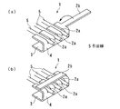
図7は本発明の第1実施例にかかる表面実装用端子を示す。図7は開口部12aを有する箱形のケース12の一方の側壁12bに表面実装用端子13を取付けた例を示す。この表面実装用端子13は、上板14と、図示の状態においてその外端部が下方に折曲形成されてなる側板15とを備えている。上板14は図示の状態においてケース側壁12bの上面12b’に載置されている。側板15の下部は内側に向かって若干折り曲げられ、ケース12の側壁12bの外面に固定するための固定部15aが形成されている。この固定部15aはなくても良い。
FIG. 7 shows a surface mounting terminal according to the first embodiment of the present invention. FIG. 7 shows an example in which a
前記上板14には適間隔でもって複数のスリット14aが櫛状に形成されている。スリット14aを形成した際の切り起こし片14bは外側に向かって延びており、ケース12内に収納されたトロイダルコイル7の引出線5を、矢印で示すようにスリット14a側へ這わせ、図7(b)に示すように、スリット14a内に収納し、溶接または半田付けし、上板14に形成された突起部14cをスリット14a側に折り曲げた後、切り起こし片14bをほぼL字状に折曲すれば面実装用の端子14b’とすることができる。
The
なお、図7(a)に示すように、ケース12の一方の側壁12bに対し対向する他方の側壁12cにも同様の表面実装用端子13が設けられる。
As shown in FIG. 7A, a similar
また、トロイダルコイル7が収納されたケース12内には耐湿、絶縁性等の観点からエポキシ樹脂のような樹脂(図示せず)が充填され、トロイダルコイル7は封止され、トランス又はインダクタ等が構成される。
The
図7(c)は、基板に取り付ける場合を示す。 FIG.7 (c) shows the case where it attaches to a board | substrate.
図8は本発明の第2実施例を示す。この実施例では、必要に応じ、端子をディスクリート用端子または面実装用端子として選択的に使用可能としたことに特徴を有している。 FIG. 8 shows a second embodiment of the present invention. This embodiment is characterized in that a terminal can be selectively used as a discrete terminal or a surface mounting terminal as required.
端子の基本構造は、図7に示した第2実施例のものにおいて、固定部15aがなく、かつ側板15の寸法が下方に向って長く形成した点を除けばほぼ同様のため、対応する部分は同じ符号で示す。
The basic structure of the terminal is substantially the same as that of the second embodiment shown in FIG. 7 except that there is no fixing
図8(a)は側板15の一部をディスクリート用端子部15cとした例である。
FIG. 8A shows an example in which a part of the
すなわち、側板15の下方中央部を内側に向かって切り起こし、ほぼ矩形状をなす切り起こし片15bの両側の下方に向かって直線的に延びる部分をそれぞれディスクリート用の端子部15cとしている。なお、切り起こし片15bは図1に示した参考例1の下板3として用いることができる。
That is, the lower central portion of the
図8(b)は上記端子部15cの先端部を外側に折り曲げ面実装用の端子部15c’としている。
In FIG. 8B, the tip of the
図8(c)は先端部を内側に折り曲げ面実装用の端子15c’としている。 In FIG. 8C, the tip portion is bent inward to form a terminal 15c 'for surface mounting.
1、1’ 表面実装用端子
2 上板
2a スリット
2b 突起部
3 下板
4 側板
5 引出線
6 金属カバー
6a 金属カバー本体
6b 側片
7 トロイダルコイル
8 台座
9 コイルボビン
9a フランジ
9b 端子部
9c フランジ
10 コイル
11 RMコア
12 ケース
12a 開口部
12b、12c 側壁
12b’ 側壁12bの上面
13 端子
14 上板
14a スリット
14b 切り起こし片
14b’ 面実装用端子部
14c 突起部
15 側板
15a 固定部
15b 切り起こし片
15c 端子部
15c’ 面実装用端子部
DESCRIPTION OF
Claims (4)
この端子は、引出線を収納する複数のスリットが形成され、かつケースに取り付けられる上板と、この上板外端部を下方に折曲形成してなる側板とを備え、
前記側板部分であってスリットの外端部に外側に向って延び、かつ折曲可能な帯状の切り起こし片が形成され、この端子部をほぼL字状に折曲し面実装用端子とすることを特徴とするコイル用端子。 At the terminal to which the coil leader is connected,
The terminal is provided with an upper plate formed with a plurality of slits for accommodating the lead lines and attached to the case, and a side plate formed by bending the outer end of the upper plate downward.
A band-shaped cut-and-raised piece which is the side plate portion and extends outward at the outer end portion of the slit and which can be bent is formed, and this terminal portion is bent into a substantially L shape to form a surface mounting terminal. This is a coil terminal.
Priority Applications (1)
| Application Number | Priority Date | Filing Date | Title |
|---|---|---|---|
| JP2005170326A JP4584040B2 (en) | 2005-06-10 | 2005-06-10 | Coil terminal |
Applications Claiming Priority (1)
| Application Number | Priority Date | Filing Date | Title |
|---|---|---|---|
| JP2005170326A JP4584040B2 (en) | 2005-06-10 | 2005-06-10 | Coil terminal |
Publications (2)
| Publication Number | Publication Date |
|---|---|
| JP2006344846A JP2006344846A (en) | 2006-12-21 |
| JP4584040B2 true JP4584040B2 (en) | 2010-11-17 |
Family
ID=37641565
Family Applications (1)
| Application Number | Title | Priority Date | Filing Date |
|---|---|---|---|
| JP2005170326A Expired - Fee Related JP4584040B2 (en) | 2005-06-10 | 2005-06-10 | Coil terminal |
Country Status (1)
| Country | Link |
|---|---|
| JP (1) | JP4584040B2 (en) |
Families Citing this family (6)
| Publication number | Priority date | Publication date | Assignee | Title |
|---|---|---|---|---|
| JP4793663B2 (en) * | 2008-04-23 | 2011-10-12 | Tdk株式会社 | Coil parts |
| JP2011108916A (en) * | 2009-11-19 | 2011-06-02 | Cosel Co Ltd | Isolation transformer |
| JP6100999B2 (en) * | 2012-01-18 | 2017-03-22 | 株式会社小糸製作所 | Method for manufacturing power supply device |
| JP2013211420A (en) * | 2012-03-30 | 2013-10-10 | Auto Network Gijutsu Kenkyusho:Kk | Substrate unit |
| JP7268289B2 (en) * | 2018-03-20 | 2023-05-08 | スミダコーポレーション株式会社 | coil parts |
| DE102021109649A1 (en) * | 2021-04-16 | 2022-10-20 | Vacuumschmelze Gmbh & Co. Kg | Inductive component with ring cores and SMD connections |
Citations (5)
| Publication number | Priority date | Publication date | Assignee | Title |
|---|---|---|---|---|
| JPH0233413U (en) * | 1988-08-25 | 1990-03-02 | ||
| JPH0245621U (en) * | 1988-09-26 | 1990-03-29 | ||
| JPH0267625U (en) * | 1988-11-09 | 1990-05-22 | ||
| JP2000100631A (en) * | 1998-09-22 | 2000-04-07 | Hitachi Media Electoronics Co Ltd | Transformer |
| JP2002359389A (en) * | 2001-05-31 | 2002-12-13 | Kitani Denki Kk | Terminal box for solar power generation module wiring |
-
2005
- 2005-06-10 JP JP2005170326A patent/JP4584040B2/en not_active Expired - Fee Related
Patent Citations (5)
| Publication number | Priority date | Publication date | Assignee | Title |
|---|---|---|---|---|
| JPH0233413U (en) * | 1988-08-25 | 1990-03-02 | ||
| JPH0245621U (en) * | 1988-09-26 | 1990-03-29 | ||
| JPH0267625U (en) * | 1988-11-09 | 1990-05-22 | ||
| JP2000100631A (en) * | 1998-09-22 | 2000-04-07 | Hitachi Media Electoronics Co Ltd | Transformer |
| JP2002359389A (en) * | 2001-05-31 | 2002-12-13 | Kitani Denki Kk | Terminal box for solar power generation module wiring |
Also Published As
| Publication number | Publication date |
|---|---|
| JP2006344846A (en) | 2006-12-21 |
Similar Documents
| Publication | Publication Date | Title |
|---|---|---|
| TWI395238B (en) | Magnetic parts | |
| JP5699133B2 (en) | Surface mount magnetic component and manufacturing method thereof | |
| EP1752997B1 (en) | Inductor | |
| JP4584040B2 (en) | Coil terminal | |
| JP2009016581A (en) | Transformer | |
| JP2008112753A (en) | Lateral low-profile coil part, and soldering method of its winding terminal | |
| JP6394820B2 (en) | Coil component and manufacturing method thereof | |
| JP5832755B2 (en) | Surface mount coil | |
| JP2009105342A (en) | Lateral coil component, bobbin, and method of connecting and fixing end of wire | |
| JP5982895B2 (en) | Coil component and manufacturing method thereof | |
| JP3942576B2 (en) | Thin transformer | |
| JP2012084776A (en) | Surface-mount closed magnetic coil | |
| JP2009218425A (en) | Coil component and method for connecting and fixing winding terminal | |
| CN109585137B (en) | Coil device | |
| JP6227245B2 (en) | Choke coil device | |
| JP4831775B2 (en) | Winding parts | |
| JP4948906B2 (en) | Coil winding parts | |
| JPH06283361A (en) | Surface mount type coil components | |
| JP2001230130A (en) | Power transformer | |
| JP7341745B2 (en) | Coil parts and bobbins | |
| JP5219151B2 (en) | Trance | |
| JP2512358Y2 (en) | Coil bobbin | |
| JP2001155934A (en) | Transformer | |
| JP2000245093A (en) | Motor | |
| JPS62230014A (en) | Transformer |
Legal Events
| Date | Code | Title | Description |
|---|---|---|---|
| A621 | Written request for application examination |
Free format text: JAPANESE INTERMEDIATE CODE: A621 Effective date: 20080425 |
|
| A711 | Notification of change in applicant |
Free format text: JAPANESE INTERMEDIATE CODE: A712 Effective date: 20100423 |
|
| A977 | Report on retrieval |
Free format text: JAPANESE INTERMEDIATE CODE: A971007 Effective date: 20100517 |
|
| A131 | Notification of reasons for refusal |
Free format text: JAPANESE INTERMEDIATE CODE: A131 Effective date: 20100608 |
|
| A521 | Request for written amendment filed |
Free format text: JAPANESE INTERMEDIATE CODE: A523 Effective date: 20100806 |
|
| TRDD | Decision of grant or rejection written | ||
| A01 | Written decision to grant a patent or to grant a registration (utility model) |
Free format text: JAPANESE INTERMEDIATE CODE: A01 Effective date: 20100831 |
|
| A01 | Written decision to grant a patent or to grant a registration (utility model) |
Free format text: JAPANESE INTERMEDIATE CODE: A01 |
|
| A61 | First payment of annual fees (during grant procedure) |
Free format text: JAPANESE INTERMEDIATE CODE: A61 Effective date: 20100901 |
|
| R150 | Certificate of patent or registration of utility model |
Free format text: JAPANESE INTERMEDIATE CODE: R150 |
|
| FPAY | Renewal fee payment (event date is renewal date of database) |
Free format text: PAYMENT UNTIL: 20130910 Year of fee payment: 3 |
|
| LAPS | Cancellation because of no payment of annual fees |