JP2010092425A - Automatic water supply machine - Google Patents
Automatic water supply machine Download PDFInfo
- Publication number
- JP2010092425A JP2010092425A JP2008264277A JP2008264277A JP2010092425A JP 2010092425 A JP2010092425 A JP 2010092425A JP 2008264277 A JP2008264277 A JP 2008264277A JP 2008264277 A JP2008264277 A JP 2008264277A JP 2010092425 A JP2010092425 A JP 2010092425A
- Authority
- JP
- Japan
- Prior art keywords
- container
- water supply
- water
- supply box
- holding
- Prior art date
- Legal status (The legal status is an assumption and is not a legal conclusion. Google has not performed a legal analysis and makes no representation as to the accuracy of the status listed.)
- Granted
Links
Images


Landscapes
- Beverage Vending Machines With Cups, And Gas Or Electricity Vending Machines (AREA)
- Devices For Dispensing Beverages (AREA)
Abstract
Description
本発明は、浄水を容器に供給して販売する水自動供給機に係り、特に、水の充填により重量が増す容器の支持構造に改良を施した水自動供給機に関するものである。 The present invention relates to an automatic water supply machine for supplying purified water to a container and selling it, and more particularly to an automatic water supply apparatus having an improved support structure for a container whose weight increases due to filling with water.
現代の消費生活では健康や安全を重視する傾向が強まっており、毎日使用する水に関しては高い水質が要求されている。単に飲料水として用いる場合には、ミネラルウォーターなどの清涼飲料水がペットボトルに詰められて販売されているが、調理や米の研ぎ水など家庭単位で大量に使う場合には、容器式の水自動販売機が利用されている。容器式の水自動販売機とは、水道水等の原水から水処理装置によって浄水を生成し、この浄水を利用者が持参した容器に給水・販売するものである。 In today's consumer life, there is an increasing tendency to place importance on health and safety, and high water quality is required for water used every day. When used simply as drinking water, soft drinks such as mineral water are packed in plastic bottles and sold, but when used in large quantities at home, such as cooking and rice sharpening water, container-type water is used. Vending machines are being used. A container-type water vending machine generates purified water from raw water such as tap water using a water treatment device, and supplies and sells this purified water to containers brought by users.
水自動販売機については、厚生労働省の規格基準のもと、食品衛生法に適合した構造の機器によって、同法が定める「清涼飲料水」が消費者に提供されている。また、清涼飲料水を持ち帰るための容器についても、容器本体から容器構成物質が溶出しないなど同法に適合した容器が利用されている。このような水自動販売機は、容器の再利用(リユース)が可能なので経済的であり、環境調和の観点からも優れている。このため、近年では、水自動販売機の需要は拡大傾向にあり、様々な技術が提案されている。 With regard to water vending machines, under the standards of the Ministry of Health, Labor and Welfare, “soft drinks” defined by the law are provided to consumers with equipment that conforms to the Food Sanitation Law. In addition, as for containers for bringing back soft drinks, containers conforming to the same law are used, for example, the container constituent materials do not elute from the container body. Such a water vending machine is economical because the container can be reused (reused), and is excellent from the viewpoint of environmental harmony. For this reason, in recent years, the demand for water vending machines has been increasing, and various techniques have been proposed.
かかる容器式の水自動販売機には、利用者が持参した容器を収容し、その容器に浄水を供給するためのスペースとして、給水ボックスが設けられている。この給水ボックスの内部には、容器を保持する保持部が設けられ、前部には扉が設けられている。利用者は、この扉を開けて、機器の前面等に貼付した説明図や保持部に表示した印等によって指示されている位置に、容器をセットする。セットされた容器に対して、洗浄等が施された後、浄水が供給される。 Such a container-type water vending machine is provided with a water supply box as a space for storing a container brought by a user and supplying purified water to the container. Inside this water supply box, a holding part for holding the container is provided, and a door is provided at the front part. The user opens the door and sets the container at a position indicated by an explanatory diagram attached to the front surface of the device or the like, a mark displayed on the holding unit, or the like. After the set container is cleaned, purified water is supplied.
このように、自動販売機内の給水ボックス内において、給水前に容器洗浄を行う装置としては、種々のものが提案されている。例えば、給水ボックス内で、空の容器内に洗浄水を供給し、容器を回転させることにより、洗浄する装置が提案されている(特許文献1、2参照)。また、給水ボックス内の下部に、給水ノズルとは別の洗浄水の供給ノズルを設け、反転させた容器の給水口に供給ノズルから洗浄水を噴出させることにより、洗浄する装置も提案されている(特許文献3〜5参照)。
As described above, various devices have been proposed as devices for cleaning containers before water supply in a water supply box in a vending machine. For example, an apparatus for cleaning by supplying cleaning water into an empty container in a water supply box and rotating the container has been proposed (see
ところで、上記のように、洗浄のために容器を回転させる水自動販売機においては、給水ボックス内で容器を保持する保持部が、モータによって回転する回転軸に取付けられている。給水を受けるために利用者が持参する空容器は軽いため、利用者が空容器を保持部にセットしても、回転軸にかかる負荷は小さい。 By the way, as mentioned above, in the water vending machine which rotates a container for washing | cleaning, the holding | maintenance part holding a container within the water supply box is attached to the rotating shaft rotated by a motor. Since the empty container brought by the user to receive water supply is light, even if the user sets the empty container on the holding part, the load on the rotating shaft is small.
しかし、給水ボックス内で給水を終えた容器は、大量の水が充填されているため、非常に重くなる。従って、かかる容器を支持する回転軸には、大きな負荷がかかる。回転軸は、せん断方向にかかる力に弱いため、このような負荷が頻繁に加わると、モータの精度や寿命に影響を与える可能性がある。 However, the container that has finished supplying water in the water supply box is very heavy because it is filled with a large amount of water. Therefore, a large load is applied to the rotating shaft that supports the container. Since the rotating shaft is weak to the force applied in the shear direction, if such a load is frequently applied, the accuracy and life of the motor may be affected.
また、容器への給水による負荷の増大と、容器の取り出しによる負荷からの解放という急激な負荷の変化を繰り返すと、軸及びその周辺の部材の金属疲労を招く可能性もある。 In addition, repeated rapid load changes such as an increase in load due to water supply to the container and release from the load due to removal of the container may lead to metal fatigue of the shaft and its surrounding members.
本発明は、このような従来技術が持つ課題を解決するために提案されたものであり、その目的は、容器への給水時に、容器を支持する軸にかかる負荷を軽減可能な水自動供給機を提供することである。 The present invention has been proposed in order to solve such problems of the prior art, and an object of the present invention is to provide an automatic water supply machine that can reduce the load on the shaft that supports the container when water is supplied to the container. Is to provide.
上記の目的を達成するため、請求項1の発明は、浄水を容器に対して供給する水自動供給機において、前記容器に浄水を供給するために、前記容器を収容可能に設けられた給水ボックスと、前記容器の給水口に浄水を供給する浄水供給部と、前記給水ボックス内に軸を中心に回転可能に設けられ、前記容器を保持する保持部と、前記軸を回転させる駆動源と、を有し、前記保持部は、前記容器を支持し、前記容器から加わる重量に応じて、前記給水ボックスの内部に接離する支持部を有することを特徴とする。
In order to achieve the above object, the invention of
以上のような請求項1の発明では、容器が浄水の供給を受けて重量物となった場合には、支持部は給水ボックスの内部に接する。このため、容器の重量が、給水ボックスへと分散され、軸にかかる負担が大幅に軽減される。
In the invention of
請求項2の発明は、請求項1の水自動供給機において、前記保持部は、前記軸が接続された基体部を有し、前記支持部は、前記給水ボックスの内部から離れる離間位置と、前記給水ボックスの内部に接する当接位置との間で変位可能となるように、基体部に設けられていることを特徴とする。
以上のような請求項2の発明では、変位する支持部という簡単な構成によって、軸にかかる負荷の軽減を図ることができる。
According to a second aspect of the present invention, in the automatic water feeder of the first aspect, the holding portion includes a base portion to which the shaft is connected, and the support portion is separated from the interior of the water supply box, It is provided in the base | substrate part so that it can displace between the contact positions which contact | connect the inside of the said water supply box.
In the invention of
請求項3の発明は、請求項2の水自動販売機において、前記支持部は、弾性部材を介して、前記基体部に取り付けられていることを特徴とする。
以上のような請求項3の発明では、弾性部材によって、支持部が離間位置に容易に復帰できる。
According to a third aspect of the present invention, in the water vending machine according to the second aspect, the support portion is attached to the base portion via an elastic member.
In the invention of
請求項4の発明は、請求項2の水自動販売機において、前記支持部は、前記基体部に対して昇降可能に設けられ、前記支持部を、離間位置に付勢する付勢部材が設けられていることを特徴とする。
以上のような請求項4の発明では、請求項2の水自動販売機において、支持部は、昇降により離間位置と当接位置との間を移動するので、支持部自体の変形等も防止される。
According to a fourth aspect of the present invention, in the water vending machine according to the second aspect, the support portion is provided so as to be movable up and down with respect to the base portion, and an urging member for urging the support portion to the separated position is provided. It is characterized by being.
In the invention according to claim 4 as described above, in the water vending machine according to
請求項5の発明は、請求項1の水自動供給機において、前記保持部は、前記軸に対して、前記容器から加わる重量に応じて移動可能に設けられていることを特徴とする。
以上のような請求項5の発明では、容器が浄水の供給を受けて重量物となった場合には、保持部が移動することにより、支持部は給水ボックスの内部に接する。このため、軸にかかる負担が、さらに軽減される。
According to a fifth aspect of the present invention, in the automatic water feeder of the first aspect, the holding portion is provided so as to be movable with respect to the shaft in accordance with a weight applied from the container.
In the invention of
以上説明したように、本発明によれば、容器への給水時に、給水ボックスを保持する軸にかかる負荷を軽減可能な水自動供給機を提供することができる。 As described above, according to the present invention, it is possible to provide an automatic water supply machine that can reduce the load on the shaft that holds the water supply box when water is supplied to the container.
続いて、本発明を実施するための最良の形態(以下「実施形態」と呼ぶ)について、図1〜図9を参照して具体的に説明する。
[実施形態の構成]
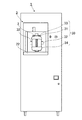
本実施形態の構成を、図1〜6を参照して説明する。本実施形態は、逆浸透膜方式を採用した容器式の水自動販売機である。なお、図1は正面図、図2は透視正面図、図3〜5は透視側面図、図6は支持部の側面図である。
Next, the best mode for carrying out the present invention (hereinafter referred to as “embodiment”) will be specifically described with reference to FIGS.
[Configuration of the embodiment]
The configuration of the present embodiment will be described with reference to FIGS. The present embodiment is a container-type water vending machine that employs a reverse osmosis membrane system. 1 is a front view, FIG. 2 is a perspective front view, FIGS. 3 to 5 are perspective side views, and FIG. 6 is a side view of a support portion.
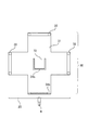
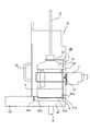
まず、図1及び図2に示すように、水自動販売機1の中央部には、ボトル型の容器2を収容するための給水ボックス3が設けられている。給水ボックス3の前部には、容器2を出し入れするための取出口6が設けられている。この取出口6には、開閉自在な給水扉5が取り付けられている。給水扉5は、正面から見て向かって左側縁部が、蝶番により水自動販売機1の正面に取り付けられ、右側縁部にハンドル部5aが固定されている。給水扉5の開閉は、利用者がハンドル部5aを持って行う。
First, as shown in FIG.1 and FIG.2, the
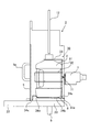
給水ボックス3の内部には、図2〜5に示すように、給水ノズル12(浄水供給部)が配置されている。この給水ノズル12には、逆浸透膜による浄水装置等(図示せず)が接続され、自動制御された弁等が開閉することにより、容器2に対して適量の浄水が供給されるように構成されている。また、給水ボックス3内には、セットされる容器2の上下左右を保持する保持部30が設けられている。利用者はこの保持部30に合わせて容器2を押し込むことにより、給水ノズル12の下部に、容器2の給水口の位置が合うように構成されている。
Inside the
保持部30は、図3に示すように、基体部31、腕部32、押え部33及び支持部34を有する。基体部31は、給水ボックス3の奥における容器2の背部に接する位置に、垂直方向に配設されたプレートである。給水ボックス3の後方にはモータ7が固定され、このモータ7の回転軸71が、給水ボックス3の背面を抜けて、基体部31に接続されている。これにより、基体部31は、モータ7の作動に従って、回転軸71を中心に回転可能に設けられている。さらに、基体部31の下端には、後方へ直角に屈曲された水平部31aが設けられている。
As shown in FIG. 3, the
腕部32は、容器2を両脇から保持する左右一対の部材である。この腕部32は、略コの字状のパイプを、基体部31の左右に固定したものであり、その前方が、容器2を挿入し易いように左右に広がっている。押え部33は容器2の肩部を支える部材である。この押え部33は、略凹の字状のパイプを、基体部31の上部に固定したものであり、その窪み部分には、容器2の給水口の根本部分が挿入される。
The
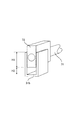
支持部34は、容器2の底部を支持する部材である。この支持部34は、基体部31の下部から前方に突出するように設けられたプレートであり、後端が上方に屈曲された後面部34a、中間が容器2の底部が乗る平面部34b、前端が下方に屈曲された前面部34cとなっている。さらに、平面部34bにおける前面部34c寄りには、段差部34dが設けられている。
The
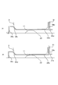
後面部34aは、平面部34bに対して、直角よりも小さい角度X(例えば、85°)で屈曲されている。そして、平面部34bの底面と水平部31aの底面とが、バネ蝶番8を介して取付けられている。このバネ蝶番8は、支持部34を基体部31に対して回動可能に接続するとともに、バネにより、支持部34を上方に付勢している。これにより、初期状態においては、後面部34aの背面が基体部31の前面に接触し、平面部34bは、前方が後方よりも高くなる勾配(例えば、5°)を有している。そして、初期状態においては、前面部34cの下端と、給水ボックス3の底面との間には、隙間Y(例えば、数mm)が形成されている。
The
また、給水ボックス3の底面部20には、逆さになった容器2の給水口に対して、非接触で対向する位置に、洗浄ノズル9(洗浄水供給部)が設けられている。洗浄ノズル9には、水道水の供給経路が接続されており、スイッチ操作等により制御される電磁弁類の開閉に応じて、水道水が噴出される構成となっている。なお、図示はしないが、スムーズな排水が可能となるように、底面部20は、その一部がメッシュ状となっている。さらに、底面部20は、外部に突出した部分がカウンター状の台板22となっている。
Further, the
[実施形態の作用]
以上のような構成を有する本実施形態は、次のように利用することができる。すなわち、利用者は、容器2のキャップを外して、ハンドル部5aを手前側に引くことによって給水扉5を開け、図2及び図3に示すように、給水ボックス3内における保持部30に合わせて、容器2を奥へ押し込む。このとき、空の容器2は軽量であるため、図6(A)に示すように、支持部34の平面部34bは勾配を維持したまま容器2を支持し、前面部34cの下端は給水ボックス3の底面部20に接していない。
[Operation of the embodiment]
The present embodiment having the above configuration can be used as follows. That is, the user removes the cap of the
そして、利用者が給水扉5を閉じると、図4に示すように、モータ7が作動して、保持部30が180°回転する。これにより、容器2が逆さまになり、その給水口が洗浄ノズル9の直上に来る。この状態で、洗浄ノズル9から洗浄用の水道水が噴出され、容器2が洗浄される。
And when a user closes the
次に、モータ7が作動して、保持部30が180°回転する。これにより、容器2が元の姿勢に復帰して、その給水口が、給水ノズル12の直下に来る。そして、給水ノズル12から容器2の給水口へ浄水が供給され、容器2内に所定量の浄水が満たされた後、給水が停止する。
Next, the
このような給水に従って容器2の重量が増すので、支持部34は、バネ蝶番8のバネの付勢力に抗して下方に回動し、図5及び図6(B)に示すように、その前面部34cの下端が給水ボックス3の底面部20に当接する。給水完了時には、支持部34の平面部34bは、水平若しくは水平よりもやや前方が下がった勾配となる。これにより、容器2を支持しているモータ7の回転軸71及び回転軸71に接続された基体部31にかかる負荷が軽減される。なお、このとき、段差部34dによって、容器2の飛び出しが防止される。
Since the weight of the
次に、利用者は、キャップによって容器2の給水口を閉じた後、容器2の側面若しくは取っ手部分を持って、容器2を手前に引き寄せる。すると、浄水で満たされた容器2は、給水ボックス3から引き出される。このように、容器2が引き出されると、容器2の重量から支持部34が解放されるので、バネ蝶番8のバネの付勢力によって、支持部34が初期状態に復帰する。これにより、前面部34cの下端と、給水ボックス3の底面部20との間には、隙間Xが形成される。
Next, the user closes the water supply port of the
[実施形態の効果]
以上のような本実施形態によれば、容器2が、浄水が満たされて重量物となった場合には、支持部34の前面部34cの端部が、給水ボックス3の底面部20に当接するので、モータ7の回転軸71にかかっていた負荷が分散される。従って、回転軸71に大きな力が集中してかかることによる故障の発生を低減し、モータ7の精度や寿命の低下を防止できる。
[Effect of the embodiment]
According to the present embodiment as described above, when the
[他の実施形態]
本発明は、上記のような実施形態に限定されるものではない。例えば、基体部、押え部、支持部等、保持部を構成する部材の形状は、上記の実施形態で例示したものには限定されない。いずれをプレート状、パイプ状、棒状等とするかは自由である。支持部34を基体部31に固定して、支持部34の弾性のみによって、底面部20への接離を可能としてもよい。
[Other Embodiments]
The present invention is not limited to the embodiment as described above. For example, the shapes of the members constituting the holding portion such as the base portion, the pressing portion, and the support portion are not limited to those exemplified in the above embodiment. Which one is plate-shaped, pipe-shaped, rod-shaped, etc. is free. The
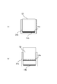
例えば、図7(A)(B)に示すように、支持部34を、基体部31に対して、上下にスライド移動可能に設けることも可能である。この場合、支持部34の後面部34aと平面部34bとの角度は、直角でよい。但し、かかる実施形態では、支持部34を上方に保持する付勢手段を設ける必要がある。
For example, as shown in FIGS. 7A and 7B, the
スライド移動は、例えば、基体部31に設けられたガイド部材(図示せず)にガイドされるように構成されている。ガイド部材の例としては、直線状のガイドレールや、後面部34aの左右の縁に対応する位置に設けられた側壁等、種々のものが考えられるが、スライド移動を実現できるものであれば、どのような構造であってもよい。
For example, the slide movement is configured to be guided by a guide member (not shown) provided in the
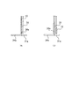
付勢手段としては、例えば、図8(A)に示すように、支持部34を吊り上げるスプリング、バネ等の弾性部材10を設けることが可能である。これにより、給水時の支持部34の急激な下降が緩和されるとともに、初期状態への復帰もスムーズとなる。
As the biasing means, for example, as shown in FIG. 8A, it is possible to provide an
なお、付勢手段は、支持部34を上方に付勢できればよいので、弾性部材10の配置方向は問わない。従って、支持部34と弾性部材10とを連結するワイヤ、ロープ等を、滑車により方向変換すれば、弾性部材10が基体部31の背後にあってもよいし(図8(B)参照)、弾性部材10の伸縮方向が横であってもよい。また、例えば、付勢手段としての自動巻リールを、ワイヤ、ロープ等を介して支持部34に連結することにより、バネの力で巻き取られる構成としてもよい。
In addition, since the biasing means should just be able to bias the
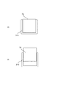
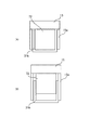
また、図9に示すように、給水ボックス3の底面部20の一部に、隆起した弾性体11を設けておいてもよい。かかる弾性体11の上面は、初期状態においては、回転する容器2の底面には接していないため(例えば、図8のように上方に付勢されている)、回転の邪魔にはならない(図9(A))。容器2に給水が開始され、支持部34が下方にスライド移動すると、支持部34の底面が、弾性体11の上部に接して、容器2の加重増加に従って、柔軟につぶれ始める(図9(B))。これにより、モータ7の回転軸71及び回転軸71に接続された基体部31にかかる負荷が、さらに軽減される。給水が完了し、容器2を取り出すと、弾性体11が元の形状に復元される。
Further, as shown in FIG. 9, a raised
弾性体11の形状や材質は、特定のものには限定されない。例えば、球形、部分球形、円柱形、角柱形、円錐形、角推形、蒲鉾形等が考えられる。材質としては、例えば、ゴム、ゲル、プラスチック、スポンジ等の樹脂、金属、木等が考えられる。弾性体11の配置位置は、洗浄ノズル9の邪魔にならない位置であればよく、単数でも複数でもよい。洗浄ノズル9の部分だけに穴が形成されたものであってもよい。
The shape and material of the
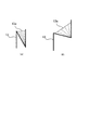
また、例えば、図10に示すように、弾性部材として、断面がN形の復元性のある連結部材13を介して、支持部34と基体部31とを連結することも可能である。かかる場合には、容器2の重量に従って、連結部材13が延びる方向に変形するので、支持部34は下降するとともに、前方に移動する。このため、給水完了時には、容器2が手前に出て、取り出し易い状態となる。なお、連結部材13には、剛性、復元性が要求されるので、弾性限界を超えないように、図11(A)(B)に示すように、扇子状状に開閉する補助プレート13aが付いていてもよい。連結部材13の材質としては、ゴム、プラスチック等の樹脂、金属等が考えられる。
For example, as shown in FIG. 10, it is also possible to connect the
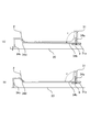
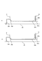
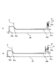
また、例えば、図12、図13に示すように、平面部34bの底面に突出した脚部34eを設けることも可能である。図12は、図6に示した実施形態において、バネ蝶番8の軸から前面部34cの前端までの長さがLである場合に、バネ蝶番8の軸からL/Nの位置に、脚部34eを設けた例である。ここで、図12(A)に示すように、待機状態においては、脚部34eの下端と底面部20までの間隔が、Y/Nとなるように設定されている。これにより、図12(B)に示すように、容器2に浄水が供給された場合、前面部34cの下端及び脚部34eの下端が底面部20に当接するので、回転軸71及び回転軸71に接続された基体部31にかかる荷重が、さらに低減される。
Further, for example, as shown in FIGS. 12 and 13, it is possible to provide a
また、図13は、図9に示した実施形態において、平面部34bの後端に脚部34eを設けた例である。ここで、図13(A)に示すように、待機状態においては、脚部34eの下端と底面部30までの間隔が、Yとなるように設定されている。これにより、図13(B)に示すように、容器2に浄水が供給された場合、前面部34cの下端及び脚部34eの下端が底面部20に当接するので、回転軸71及び回転軸71に接続された基体部31にかかる荷重が、さらに低減される。
FIG. 13 is an example in which a
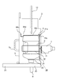
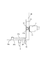
また、図14〜図16に示すように、角軸部72と軸受部31bによる負荷軽減を図ることも可能である。角軸部72は、回転軸71の先端に設けられた直方体形状の部材である。軸受部31bは、基体部31の背面に固定された略コの字状(凹状)の部材である。軸受部31bの内部に、角軸部72が挿入されることにより、回転軸71の回転とともに、保持部30及びこれに搭載された容器2も回転する。したがって、モータ7が作動して、保持部30が180°回転することにより、容器2が逆さまになり、その給水口が洗浄ノズル9の直上に来るので、洗浄ノズル9による容器2の洗浄が可能となる。
Moreover, as shown in FIGS. 14-16, it is also possible to reduce the load by the
そして、モータ7が作動して、保持部30が180°回転すると、容器2が元の姿勢に復帰して、その給水口が、給水ノズル12の直下に来る。給水ノズル12から容器2の給水口へ浄水が供給されると、容器2の重量が増すので、図14(B)、図15に示すように、軸受部31bが、角軸部72からずれて下方へスライド移動して、支持部34が底面部20に当接する。これにより、モータ7の回転軸71及び回転軸71に接続された基体部31にかかる負荷が、さらに軽減される。
Then, when the
かかる角軸部72と軸受部31bを用いた場合には、給水により下降した保持部30を、待機時のために上方に復帰させる必要がある。そのための構造としては、上記の実施形態で示したものも考えられるが、次のような例も適用可能である。
When such a
すなわち、図17に示すように、角軸部72の底面と、軸受部31bの内面に、磁石14a,14bを取り付ける構造が考えられる。かかる場合には、図17(B)に示すように、給水時には、磁力に抗して軸受部31bが下降するが、容器2が取り出されると、図17(A)に示すように、磁力によって軸受部31bが上昇して元の位置に復帰する。なお、磁石14a,14bの隙間は、図17では大きく示しているが、実際には数mm程度で良い。
That is, as shown in FIG. 17, a structure in which the
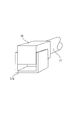
また、図18に示すように、角軸部72に吊上具15を設け、吊上部15の取り付けられた弾性部材15aによって、軸受部31bを保持する構造が考えられる。かかる場合には、図18(B)に示すように、給水時には、弾性部材15aが延びて軸受部31bが下降するが、容器2が取り出されると、図18(A)に示すように、弾性部材15aの復元力によって、軸受部31bが上昇して元の位置に復帰する。なお、弾性部材15aの材質や形状も、上記の弾性体11で示したと同様に、自由である。
Moreover, as shown in FIG. 18, the structure which hold | maintains the
さらに、図19に示すように、保持部30の下方に、バンパー、シリンダ等の押上部材16を設ける構造も考えられる。かかる場合には、給水時には、押上部材16の付勢力に抗して軸受部31bが下降するが、容器2が取り出されると、押上部材16の付勢力によって軸受部31bが上昇して元の位置に復帰する。押上部材16の付勢力は、弾性体によるもの、気圧若しくは液圧による物等、どのようなものによって得てもよい。なお、上記は、保持部30を自動的に復帰させる構造の例であるが、テコ等の利用により、手動により復帰させる構造も適用可能である。
Furthermore, as shown in FIG. 19, a structure in which a push-up
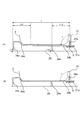
また、図20に示すように、角軸部72及び軸受部31bは、スライド方向に長く形成されている方が、スライド時のぶれによる精度の低下が押えられる。この場合、上述のように、図20中、スライド長H2は、数mm程度あれば十分であるので、H1が長くなるように工夫することになる。なお、上記の角軸部72及び軸受部31bは、断面が四角であったが、例えば、角がない長円形とU字形の組み合わせでもよい。
In addition, as shown in FIG. 20, when the
また、図21に示すように、台板22の高さを、支持部30の高さに合わせることによって、容器2を取り出し易い構成とすることも可能である。また、給水ノズル12や洗浄ノズル9を複数にすることはもちろん、形状を可変としたり、異なる形状のものに交換可能としたり、位置が移動するように構成してもよい。給水ノズル12と洗浄ノズル9を共通のノズルとしてもよい。洗浄時や給水時の容器2の方向も上記のものには限定されない。洗浄時に、回転軸71を中心に、容器2を回動若しくは揺動させてもよい。
In addition, as shown in FIG. 21, the
回転軸71は、モータ7のシャフトでもよいが(ダイレクトドライブ)、ギヤ機構やベルト等により、モータ7の動力が間接的に伝達されるものであってもよい。容器2の洗浄に用いる水は、上記の実施形態で例示したものよりも、さらに精緻な処理水でもよい。上記の容器洗浄、容器搬送、給水のいずれかの領域において、紫外線照射による殺菌処理を施してもよい。さらに、浄水装置の種類、金銭の収集方法等も特定のものには限定されない。販売を目的としない浄水を供給する装置にも適用可能である。
The rotating
1…水自動販売機
2…容器
3…給水ボックス
5…給水扉
5a…ハンドル部
6…取出口
7…モータ
8…バネ蝶番
9…洗浄ノズル
10,15a…弾性部材
11…弾性体
12…給水ノズル
13…連結部材
14a,14b…磁石
15…吊上具
20…底面部
22…台板
30…保持部
31…基体部
31a…水平部
32…腕部
33…押え部
34…支持部
34a…後面部
34b…平面部
34c…前面部
34d…段差部
34e…脚部
71…回転軸
DESCRIPTION OF
Claims (5)
前記容器に浄水を供給するために、前記容器を収容可能に設けられた給水ボックスと、
前記容器の給水口に浄水を供給する浄水供給部と、
前記給水ボックス内に軸を中心に回転可能に設けられ、前記容器を保持する保持部と、
前記軸を回転させる駆動源と、
を有し、
前記保持部は、前記容器を支持し、前記容器から加わる重量に応じて、前記給水ボックスの内部に接離する支持部を有することを特徴とする水自動供給機。 In an automatic water supply machine that supplies purified water to a container,
In order to supply purified water to the container, a water supply box provided to accommodate the container;
A purified water supply unit for supplying purified water to the water supply port of the container;
A holding portion that is rotatably provided around an axis in the water supply box and holds the container;
A drive source for rotating the shaft;
Have
The said holding | maintenance part supports the said container, and has a support part which contacts / separates the inside of the said water supply box according to the weight added from the said container, The automatic water supply machine characterized by the above-mentioned.
前記支持部は、前記給水ボックスの内部から離れる離間位置と、前記給水ボックスの内部に接する当接位置との間で変位可能となるように、基体部に設けられていることを特徴とする請求項1記載の水自動供給機。 The holding part has a base part to which the shaft is connected,
The said support part is provided in the base | substrate part so that it can displace between the space | interval position which leaves | separates from the inside of the said water supply box, and the contact position which contact | connects the inside of the said water supply box. Item 1. An automatic water feeder according to item 1.
前記支持部を、離間位置に付勢する付勢部材が設けられていることを特徴とする請求項2記載の水自動供給機。 The support part is provided to be movable up and down with respect to the base part.
The automatic water feeder according to claim 2, further comprising an urging member that urges the support portion to a separated position.
Priority Applications (1)
| Application Number | Priority Date | Filing Date | Title |
|---|---|---|---|
| JP2008264277A JP5382684B2 (en) | 2008-10-10 | 2008-10-10 | Automatic water feeder |
Applications Claiming Priority (1)
| Application Number | Priority Date | Filing Date | Title |
|---|---|---|---|
| JP2008264277A JP5382684B2 (en) | 2008-10-10 | 2008-10-10 | Automatic water feeder |
Publications (2)
| Publication Number | Publication Date |
|---|---|
| JP2010092425A true JP2010092425A (en) | 2010-04-22 |
| JP5382684B2 JP5382684B2 (en) | 2014-01-08 |
Family
ID=42255045
Family Applications (1)
| Application Number | Title | Priority Date | Filing Date |
|---|---|---|---|
| JP2008264277A Expired - Fee Related JP5382684B2 (en) | 2008-10-10 | 2008-10-10 | Automatic water feeder |
Country Status (1)
| Country | Link |
|---|---|
| JP (1) | JP5382684B2 (en) |
Cited By (3)
| Publication number | Priority date | Publication date | Assignee | Title |
|---|---|---|---|---|
| JP2012086887A (en) * | 2010-10-22 | 2012-05-10 | San Denshi Kogyo Kk | Automatic water supply machine |
| CN108652449A (en) * | 2017-03-28 | 2018-10-16 | 佛山市顺德区美的饮水机制造有限公司 | Electric motor mounting structure and water dispenser for water dispenser |
| WO2020206564A1 (en) * | 2019-04-10 | 2020-10-15 | Inversiones Bayou Spa | Rotary system for washing and filling with liquid in returnable containers |
Citations (2)
| Publication number | Priority date | Publication date | Assignee | Title |
|---|---|---|---|---|
| JPS61210354A (en) * | 1985-03-15 | 1986-09-18 | Konishiroku Photo Ind Co Ltd | Liquid replenishing method |
| JP2003317144A (en) * | 2002-04-24 | 2003-11-07 | Kansai Raw Material:Kk | Method for washing bottle and automatic vending machine for drinking water using the same |
-
2008
- 2008-10-10 JP JP2008264277A patent/JP5382684B2/en not_active Expired - Fee Related
Patent Citations (2)
| Publication number | Priority date | Publication date | Assignee | Title |
|---|---|---|---|---|
| JPS61210354A (en) * | 1985-03-15 | 1986-09-18 | Konishiroku Photo Ind Co Ltd | Liquid replenishing method |
| JP2003317144A (en) * | 2002-04-24 | 2003-11-07 | Kansai Raw Material:Kk | Method for washing bottle and automatic vending machine for drinking water using the same |
Cited By (4)
| Publication number | Priority date | Publication date | Assignee | Title |
|---|---|---|---|---|
| JP2012086887A (en) * | 2010-10-22 | 2012-05-10 | San Denshi Kogyo Kk | Automatic water supply machine |
| CN108652449A (en) * | 2017-03-28 | 2018-10-16 | 佛山市顺德区美的饮水机制造有限公司 | Electric motor mounting structure and water dispenser for water dispenser |
| CN108652449B (en) * | 2017-03-28 | 2024-05-03 | 佛山市顺德区美的饮水机制造有限公司 | Motor mounting structure for water dispenser and water dispenser |
| WO2020206564A1 (en) * | 2019-04-10 | 2020-10-15 | Inversiones Bayou Spa | Rotary system for washing and filling with liquid in returnable containers |
Also Published As
| Publication number | Publication date |
|---|---|
| JP5382684B2 (en) | 2014-01-08 |
Similar Documents
| Publication | Publication Date | Title |
|---|---|---|
| JP5382684B2 (en) | Automatic water feeder | |
| WO2004101122A3 (en) | Method and apparatus for mass based dispensing | |
| PL2322443T3 (en) | Height-adjustable transport container | |
| WO2009012011A8 (en) | Clean in place system for beverage dispensers | |
| HK1100045A1 (en) | On-line adaptive model predictive control in a process control system | |
| SI1626925T1 (en) | A method for dispensing a beverage and devices therefor | |
| MX2010005712A (en) | Brewing unit for preparing beverages from single service packages and machines comprising said unit. | |
| HK1105108A1 (en) | Machine for percolating a beverage from powdered material in a container | |
| WO2009007845A3 (en) | Welding wire guide ring with sloped surface | |
| ATE503406T1 (en) | SELF-FEEDING DEVICE | |
| PL1559352T3 (en) | Percolating machine for making beverages | |
| JP4837358B2 (en) | Bottle drinking water filling device | |
| WO2018079450A1 (en) | Container storage device and beverage dispenser | |
| CN105303701A (en) | Raw material supply device for cup type vending machine | |
| JP5003146B2 (en) | Cup supply device for cup beverage supply device | |
| JP6173779B2 (en) | Bottle drinking water filling device | |
| WO2006074136A3 (en) | Bottle holder | |
| GB2430764B (en) | On-line adaptive model predictive control in a process control system | |
| TW200628375A (en) | Container for receiving sheet-like articles | |
| JP6394122B2 (en) | Cup supply device for cup beverage supply device | |
| JP3777375B2 (en) | Water vending machine | |
| KR102307150B1 (en) | Beverage discharging apparatus | |
| JP7522296B2 (en) | Beverage dispenser with container cleaning system | |
| JP2010189057A (en) | Beverage dispenser | |
| KR100531944B1 (en) | Automobile cup holder |
Legal Events
| Date | Code | Title | Description |
|---|---|---|---|
| A621 | Written request for application examination |
Free format text: JAPANESE INTERMEDIATE CODE: A621 Effective date: 20111007 |
|
| A521 | Request for written amendment filed |
Free format text: JAPANESE INTERMEDIATE CODE: A523 Effective date: 20120816 |
|
| A521 | Request for written amendment filed |
Free format text: JAPANESE INTERMEDIATE CODE: A523 Effective date: 20120808 |
|
| A977 | Report on retrieval |
Free format text: JAPANESE INTERMEDIATE CODE: A971007 Effective date: 20130524 |
|
| A131 | Notification of reasons for refusal |
Free format text: JAPANESE INTERMEDIATE CODE: A131 Effective date: 20130611 |
|
| A521 | Request for written amendment filed |
Free format text: JAPANESE INTERMEDIATE CODE: A523 Effective date: 20130805 |
|
| TRDD | Decision of grant or rejection written | ||
| A01 | Written decision to grant a patent or to grant a registration (utility model) |
Free format text: JAPANESE INTERMEDIATE CODE: A01 Effective date: 20130827 |
|
| A61 | First payment of annual fees (during grant procedure) |
Free format text: JAPANESE INTERMEDIATE CODE: A61 Effective date: 20130925 |
|
| R150 | Certificate of patent or registration of utility model |
Ref document number: 5382684 Country of ref document: JP Free format text: JAPANESE INTERMEDIATE CODE: R150 Free format text: JAPANESE INTERMEDIATE CODE: R150 |
|
| R250 | Receipt of annual fees |
Free format text: JAPANESE INTERMEDIATE CODE: R250 |
|
| R250 | Receipt of annual fees |
Free format text: JAPANESE INTERMEDIATE CODE: R250 |
|
| R250 | Receipt of annual fees |
Free format text: JAPANESE INTERMEDIATE CODE: R250 |
|
| R250 | Receipt of annual fees |
Free format text: JAPANESE INTERMEDIATE CODE: R250 |
|
| R250 | Receipt of annual fees |
Free format text: JAPANESE INTERMEDIATE CODE: R250 |
|
| LAPS | Cancellation because of no payment of annual fees |