JP2010090822A - Vertical shaft valve type hydraulic turbine generator - Google Patents
Vertical shaft valve type hydraulic turbine generator Download PDFInfo
- Publication number
- JP2010090822A JP2010090822A JP2008262119A JP2008262119A JP2010090822A JP 2010090822 A JP2010090822 A JP 2010090822A JP 2008262119 A JP2008262119 A JP 2008262119A JP 2008262119 A JP2008262119 A JP 2008262119A JP 2010090822 A JP2010090822 A JP 2010090822A
- Authority
- JP
- Japan
- Prior art keywords
- water
- flow path
- opening
- horizontal
- swash plate
- Prior art date
- Legal status (The legal status is an assumption and is not a legal conclusion. Google has not performed a legal analysis and makes no representation as to the accuracy of the status listed.)
- Granted
Links
Images


Classifications
-
- Y—GENERAL TAGGING OF NEW TECHNOLOGICAL DEVELOPMENTS; GENERAL TAGGING OF CROSS-SECTIONAL TECHNOLOGIES SPANNING OVER SEVERAL SECTIONS OF THE IPC; TECHNICAL SUBJECTS COVERED BY FORMER USPC CROSS-REFERENCE ART COLLECTIONS [XRACs] AND DIGESTS
- Y02—TECHNOLOGIES OR APPLICATIONS FOR MITIGATION OR ADAPTATION AGAINST CLIMATE CHANGE
- Y02E—REDUCTION OF GREENHOUSE GAS [GHG] EMISSIONS, RELATED TO ENERGY GENERATION, TRANSMISSION OR DISTRIBUTION
- Y02E10/00—Energy generation through renewable energy sources
- Y02E10/20—Hydro energy
Landscapes
- Hydraulic Turbines (AREA)
Abstract
Description
本発明は、水平流路を流れる水を縦方向流路に取り込んで水車に供給する立軸バルブ型水車発電設備に関する。 The present invention relates to a vertical shaft type water turbine power generation facility that takes water flowing in a horizontal flow channel into a vertical flow channel and supplies the water to a water turbine.
水車にプロペラ状の翼を用いて回転させるとともに、あわせて設置されるガイドベーンも可動とし、水車を通過する流体の流量変化に対して、高い効率で運転できるようにしたものをカプラン水車という。そのカプラン水車を用いた発電設備の一種である立軸バルブ型水力発電設備は、比較的低落差用に適用されることが多い。 A Kaplan turbine is a type of turbine that uses propeller-shaped blades to rotate the turbine, and the guide vanes that are installed together are movable so that it can be operated with high efficiency against changes in the flow rate of fluid passing through the turbine. Vertical shaft type hydroelectric power generation equipment, which is a kind of power generation equipment using the Kaplan turbine, is often applied for a relatively low head.
このため、水車上方の水平流路上部水面から縦方向流路の入口に至るまでの鉛直方向距離がフランシス水車などに比べて短い。また、同様に水車内を流れる水量が相対的に多い。
例えば特許文献1に開示されているように、立軸バルブ型水力発電設備を運転したときに、水平流路の水面から水車に向かって、空気吸込み渦といわれる強い旋回速度成分を有するロープ状の渦流が局所的に発生する場合がある。
For example, as disclosed in
この渦(空気吸い込み渦)は水車運転によって水が急激に水車流路へと吸引されることによって発生するものであるが、水面から水車へと連続的に発生する。このために、水車にはこの渦による大きな水力エネルギ損失が発生したり、渦が水車に衝突することで振動や騒音を発生し水車をはじめとする主要機器の運転にも支障をきたしたりすることになる。 This vortex (air suction vortex) is generated when water is suddenly sucked into the water turbine channel by the operation of the water turbine, but continuously generated from the water surface to the water turbine. For this reason, a large hydraulic energy loss due to this vortex occurs in the water turbine, and the vortex collides with the water turbine to generate vibration and noise, which may hinder the operation of main equipment such as the water turbine. become.
一般にこの空気吸込み渦は、水が流れる流路の形状に密接に関係するものであり、水平流路の水流方向速度の不均一性が旋回方向の流れを発達させ渦流となって成長するものである。また、この空気吸込み渦は、流路内のフローパターンの均一性と深く関係するものであり、流路内のフローパターンが一様で乱れがない場合は渦が発生しないことが知られている。 In general, this air suction vortex is closely related to the shape of the flow path through which water flows, and the non-uniformity of the horizontal flow speed in the horizontal flow path develops a swirl flow and grows as a vortex flow. is there. In addition, this air suction vortex is deeply related to the uniformity of the flow pattern in the flow path, and it is known that the vortex does not occur when the flow pattern in the flow path is uniform and not disturbed. .
しかし、水平流路内のフローパターンを一様にすることは、土木工事上の制限や施工上の問題等があり困難な場合が多く、このために空気吸込み渦が発生し易い状況となっている。 However, it is often difficult to make the flow pattern in the horizontal flow path uniform due to limitations in civil engineering work and problems in construction, etc., which makes it easy to generate air suction vortices. Yes.
立軸バルブ型水力発電所の水路のように、水平流路の末端底部に開口部(給水口)を有し、水平流路の下方の垂直方向に縦方向流路を形成する場合、水流の方向は水平方向から鉛直下向きに変えられるため、水平流路の末端部には下降流れが生じることになる。そのため水面に発生する渦は下方に向かって伸長しやすくなる場合がある。このとき、水平流路の水位が低くなり、水車の水量が多いほど渦強度が増し空気吸込み渦となり、縦方向流路の給水口に向かって空気が連続的あるいは断続的に吸い込まれるようになる。 When the vertical flow path is formed in the vertical direction below the horizontal flow path with an opening (water supply port) at the bottom end of the horizontal flow path, as in the case of a vertical valve type hydroelectric power station, the direction of water flow Is changed from the horizontal direction to the vertically downward direction, a downward flow is generated at the end of the horizontal flow path. Therefore, the vortex generated on the water surface may be easily extended downward. At this time, as the water level in the horizontal flow path becomes lower and the amount of water in the water turbine increases, the vortex strength increases and an air suction vortex is generated, and air is sucked continuously or intermittently toward the water supply port of the vertical flow path. .
この空気吸込み渦の発生により、水車内に空気が流入することで水車運転状態に変動が生じ水車主機をはじめとする機器の運転にも支障をきたす場合がある。また、水車には大きなエネルギ損失が発生する。 Occurrence of this air suction vortex may cause fluctuations in the operation state of the water turbine due to air flowing into the water turbine, which may hinder the operation of equipment such as the main turbine. In addition, a large energy loss occurs in the water turbine.
このような空気吸込み渦を回避する方法は、例えば、特許文献1に開示されているように、発電機のバルブの上面部に一端を固定支持して他端を流水路に突出した整流棒を配置することによって、水流は整流棒を中心とした穏やかな旋回を有する流れとなり局部的渦流が発生しにくくなることが知られている。
As a method for avoiding such air suction vortex, for example, as disclosed in
しかし、この方法では、渦が発生して棒のまわりに定常的にまとわりついた場合、渦により丸棒が加振力を受けて振動するようになり、構造物の健全性上好ましくない場合も考えられる。 However, with this method, when a vortex is generated and the rod is steadily gathered around the rod, the vortex will cause the round bar to vibrate due to the excitation force, which may be undesirable for the soundness of the structure. It is done.
また特許文献2に開示されているように、水平流路から水を取り入れるための導水口の水面付近に、ほぼ水平となるように水平整流板を配置することによって、渦の発生を抑制させることなどが知られている。
Moreover, as disclosed in
また汎用のポンプでは、上記のような空気吸込み渦を回避する手段として、吸込み配管形状の適正化や旋回流抑制の吸込み装置等が考察されているが、立軸バルブ水車においては、そのようなものが実用化されていない。 In general-purpose pumps, as a means for avoiding the above-mentioned air suction vortex, optimization of the shape of the suction pipe and a suction device for suppressing swirl flow have been considered. Has not been put to practical use.
以上述べたように、立軸バルブ型水車発電設備においては、水車の流水路を形成する水面に空気の吸込みによる渦流が、水車に向かって発生する。この空気吸込み渦が水車に到達すると、水力エネルギ損失が増大し水車性能が低下する。仮に運転可能であっても、水車性能の低下は避けられない。 As described above, in the vertical shaft type water turbine power generation facility, a vortex flow due to air suction is generated toward the water turbine on the water surface forming the water channel of the water turbine. When this air suction vortex reaches the water turbine, hydraulic energy loss increases and the turbine performance decreases. Even if it is possible to drive, a decrease in turbine performance is inevitable.
この水車は、低落差領域に適用されることから、比較的小さな損失であっても有効落差に対する比率として表される水車損失の観点からは、無視できない大きなものになる。また、渦流が水車に衝突および接触する際には、騒音および振動等の水車の運転に支障を来たす現象が生ずる。 Since this water turbine is applied to the low head region, even a relatively small loss becomes a large one that cannot be ignored from the viewpoint of the water turbine loss expressed as a ratio to the effective head. Further, when the eddy current collides with and comes into contact with the water turbine, a phenomenon that disturbs the operation of the water turbine such as noise and vibration occurs.
本発明は上記課題を解決するためになされたものであって、その目的は、立軸バルブ型水車発電設備における空気吸込み渦の発生を抑制することにある。 The present invention has been made to solve the above-described problems, and an object of the present invention is to suppress the generation of air suction vortices in a vertical shaft type water turbine power generation facility.
上記目的を達成するための本発明に係る立軸バルブ型水車発電設備は、回転軸が鉛直方向を向くように配置された水車と、前記水車に接続されてその水車によって駆動される発電機と、自由水面が形成されて給水口から終端部近くの前記水車の上方に向かってほぼ水平に水が流れるように形成された水平流路と、前記水平流路の底部の前記終端部寄りに形成された開口部から前記発電機に向かって下向きに延びて、前記水平流路を流通した水が前記水車に向かって下向きに流れるように形成された縦方向流路と、前記開口部の上方の前記自由水面近傍に配置されて、前記終端部側が下がるように前記自由水面に対して所定の傾きを保ち、前記終端部側が前記自由水面下にあるように配置された斜板と、を有することを特徴とする。 In order to achieve the above object, an upright valve type water turbine power generation facility according to the present invention includes a water turbine arranged such that a rotating shaft faces a vertical direction, a generator connected to the water turbine and driven by the water turbine, A free water surface is formed, and a horizontal flow path is formed so that water flows substantially horizontally from the water supply port to the upper part of the water wheel near the end portion, and is formed near the end portion at the bottom of the horizontal flow path. A vertical flow path that extends downward from the opening toward the generator and is formed such that water flowing through the horizontal flow path flows downward toward the water wheel, and the upper portion above the opening. A swash plate disposed near the free water surface, maintaining a predetermined inclination with respect to the free water surface so that the end portion side is lowered, and disposed so that the end portion side is below the free water surface. Features.
また、本発明に係る立軸バルブ型水車発電設備は、回転軸が鉛直方向を向くように配置された水車と、前記水車に接続されてその水車によって駆動される発電機と、自由水面が形成されて給水口から終端部近くの前記水車の上方に向かってほぼ一定の幅でほぼ水平に水が流れるように形成された水平流路と、前記水平流路の底部の前記終端部寄りに形成された開口部から前記発電機に向かって下向きに延びて、前記水平流路を流通した水が前記水車に向かって下向きに流れるように形成された縦方向流路と、それぞれが前記開口部の上方で前記水平流路の両側の壁面それぞれに取り付けられて前記終端部側が前記自由水面下にあるように且つ前記終端部側が下がるように前記自由水面に対して所定の傾きを保つように配置されて、前記開口部の上方が開放されるように構成された斜板と、を有することを特徴とする。 Further, the vertical shaft type water turbine power generation equipment according to the present invention includes a water turbine arranged so that a rotating shaft faces a vertical direction, a generator connected to the water turbine and driven by the water turbine, and a free water surface. A horizontal channel formed so that water flows almost horizontally with a substantially constant width from the water supply port to the upper part of the water wheel near the terminal part, and formed near the terminal part at the bottom of the horizontal channel. A vertical flow path that extends downward from the opening toward the generator and is formed such that water flowing through the horizontal flow path flows downward toward the water turbine, and each is above the opening. Attached to each of the wall surfaces on both sides of the horizontal flow path, and arranged so as to maintain a predetermined inclination with respect to the free water surface so that the terminal end side is below the free water surface and the terminal end side is lowered. The opening Upward and having a swash plate which is configured to be opened.
また、本発明に係る立軸バルブ型水車発電設備は、回転軸が鉛直方向を向くように配置された水車と、前記水車に接続されてその水車によって駆動される発電機と、自由水面が形成されて給水口から終端部近くの前記水車の上方に向かってほぼ水平に水が流れるように形成されて、前記給水口から前記開口部の前記給水口側端部までほぼ一定の幅になるように形成された水平流路と、前記水平流路の底部の前記終端部寄りに形成された円形の開口部から前記発電機に向かって下向きに延びて、前記水平流路を流通した水が前記水車に向かって下向きに流れるように形成された縦方向流路と、を有し、前記開口部の上方の前記水平流路の両側の壁面それぞれには、前記終端部側が下がるように且つ前記自由水面に対して所定の傾きを有し前記開口部の上方が開放されるように構成された傾斜面が形成されていること、を特徴とする。 Further, the vertical shaft type water turbine power generation equipment according to the present invention includes a water turbine arranged so that a rotating shaft faces a vertical direction, a generator connected to the water turbine and driven by the water turbine, and a free water surface. The water is formed so that the water flows substantially horizontally from the water supply port to the upper part of the water wheel near the terminal end, and has a substantially constant width from the water supply port to the water supply port side end of the opening. The water that has flowed through the horizontal flow path and extends downward from the circular flow path formed near the terminal end of the horizontal flow path and the end of the horizontal flow path toward the generator. A vertical flow path formed to flow downward toward the surface, and on each of the wall surfaces on both sides of the horizontal flow path above the opening, the free end surface is provided so that the end side is lowered. Having a predetermined inclination with respect to the opening The inclined surface above parts is configured to be opened is formed, characterized by.
また、本発明に係る立軸バルブ型水車発電設備は、回転軸が鉛直方向を向くように配置された水車と、前記水車に接続されてその水車によって駆動される発電機と、自由水面が形成されて給水口から終端部近くの前記水車の上方に向かってほぼ水平に水が流れるように形成された水平流路と、前記水平流路の底部の前記終端部寄りに形成された開口部から前記発電機に向かって下向きに延びて、前記水平流路を流通した水が前記水車に向かって下向きに流れるように形成された縦方向流路と、前記水平流路底部から上方に延びて、前記開口部よりも前記終端部側で、前記水平流路の両側の壁面それぞれと前記終端部とからなる隅部それぞれを水平方向から覆うように配置された多孔質部材の隔壁と、を有することを特徴とする。 Further, the vertical shaft type water turbine power generation equipment according to the present invention includes a water turbine arranged so that a rotating shaft faces a vertical direction, a generator connected to the water turbine and driven by the water turbine, and a free water surface. A horizontal flow path formed so that water flows substantially horizontally from the water supply port to the upper portion of the water wheel near the terminal end, and an opening formed near the terminal end of the bottom of the horizontal flow path. A vertical flow channel that extends downward toward the generator and is formed such that water flowing through the horizontal flow channel flows downward toward the water turbine, and extends upward from the bottom of the horizontal flow channel, A partition wall of a porous member arranged so as to cover each of the wall surfaces on both sides of the horizontal flow path and the corners made of the terminal portion from the horizontal direction on the terminal portion side of the opening. Features.
本発明によれば、立軸バルブ型水車発電設備における空気吸込み渦の発生を抑制することが可能となる。 ADVANTAGE OF THE INVENTION According to this invention, it becomes possible to suppress generation | occurrence | production of the air suction vortex in a vertical shaft type | mold water turbine power generation equipment.
以下、本発明に係る立軸バルブ型水車発電設備の実施形態について、図面を参照して説明する。 DESCRIPTION OF EMBODIMENTS Hereinafter, an embodiment of a vertical shaft type water turbine power generation facility according to the present invention will be described with reference to the drawings.
[第1の実施形態]
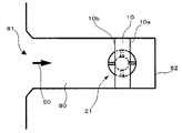
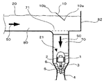
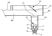
先ず、図1および図2を用いて本発明の立軸バルブ型水車発電設備に係る第1の実施形態の構成および作用について説明する。図1は、本実施形態の立軸バルブ型水車発電設備を示す概略平面図である。図2は、図1の概略側断面図である。
[First Embodiment]
First, the configuration and operation of the first embodiment according to the vertical shaft type water turbine power generation facility of the present invention will be described with reference to FIGS. 1 and 2. FIG. 1 is a schematic plan view showing an upright valve type water turbine power generation facility of the present embodiment. FIG. 2 is a schematic sectional side view of FIG.
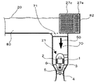
本実施形態の立軸バルブ型水車発電設備は、自由水面20が形成されて給水口81から終端部82に向かってほぼ水平に水が流れる水平流路80と、水平流路80の底部の終端部82寄りに形成された円形の開口部71から下向きに延びて水平流路80を流通した水が下向きに流れるように形成された縦方向流路70と、を有する。水平流路80の給水口81付近の水流方向および縦方向流路70の開口部71より下方の水流方向は、矢印50で示している。
The vertical shaft type water turbine power generation facility according to the present embodiment includes a
縦方向流路70の下方には、鉛直に延びる主軸3を有する水車発電機21が配置されている。
A
水車発電機21は、たまご型をしたバルブ1を有し、このバルブ1内には発電機固定子および回転子を主要構成部材とした発電機2が配置されている。主軸3は鉛直方向に配置され、主軸3の上方側の端部には、回転子が結合されており、下方側の端部にはランナ4が取り付けられている。
The
このランナ4の上方には流量を調節するガイドベーン5が複数枚円周状に配置されており、複数のガイドベーン5は、これらの外周部に位置するリンク機構等により連動するように形成されている。
Above the
ガイドベーン5の上方側(上流側)にはバルブ1を支えるためのステー6と呼ばれる支持部材が、バルブ1から縦方向流路70の外側に向かって放射状に配置されている。また、発電機2の内部を点検するための点検口が、バルブ1の上方と下方それぞれに配置されている。
On the upper side (upstream side) of the
さらに、開口部71の上方の自由水面20近傍には、斜板10が配置されている。この斜板10は、水平流路80の短手方向長さ、すなわち水平流路80の幅と、ほぼ同じ幅の略長方形状の平板である。この斜板10の終端部82側の終端部側端辺10aが下がるように自由水面20に対して所定の傾きを保ち、終端部側端辺10aが自由水面20より下方にあるように、すなわち水没するように固定されている。終端部側端辺10aは、自由水面20とほぼ平行になるように配置しておくとよい。
Further, the
斜板10の給水口側端辺10bの自由水面20からの高さは、空気吸込み渦は最低水位のときに最も発生しやすいので、自由水面20の水位が最低水位のときに、水平流路80を流れる水が給水口側端辺10bを乗り越えられない程度の高さ以上となるように設定しておくとよい。
The height of the water
本実施形態によれば、水車発電機21を運転するときには、水平流路80の給水口81側から終端部82に向かって水平に流れる水は、斜板10によって下向きに偏向されてスムーズに開口部71に流入される。このとき、水平流路80の給水口81側(上流側)で発生した小さな剥離渦が壊されるため、斜板10よりも終端部82側(下流側)の水面は安定し終端部82近傍で渦が発生することを抑制可能になる。
According to the present embodiment, when the
これにより、水面から水車発電機21に向かって発生する空気吸込み渦の発生を抑制できる。したがって、エネルギ損失を抑制し効率的に水車発電機21を運転することが可能になる。
Thereby, generation | occurrence | production of the air suction vortex generated toward the
[第2の実施形態]
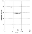
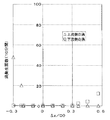
本発明に係る立軸バルブ型水車発電設備の第2の実施形態について図3〜図7を用いて以下に説明する。この実施形態は第1の実施形態の変形例であって、第1の実施形態と同一部分または類似部分には、同一符号を付して、重複説明を省略する。図3は、本実施形態の立軸バルブ型水車発電設備を示す概略平面図である。図4は、図3の概略側断面図である。図5は、斜板10と自由水面20とのなす角度αを定めるために模型実験を行って、角度αと渦発生回数との関係を検討した結果を示したグラフである。図6は、終端部側端辺10aの水没深さhを定めるために模型実験を行って、水没深さhおよび開口部直径D0の比(h/D0)と、渦発生回数との関係を検討した結果を示したグラフである。図7は、開口部71と斜板10との相対位置を定めるために模型実験を行って、水平幅方向交線10cおよび開口部71中心の水平距離ΔXと開口部71の直径D0との比に対する渦発生回数を検討した結果を示したグラフである。
[Second Embodiment]
A second embodiment of the vertical shaft type water turbine power generation facility according to the present invention will be described below with reference to FIGS. This embodiment is a modification of the first embodiment, and the same or similar parts as those of the first embodiment are denoted by the same reference numerals, and redundant description is omitted. FIG. 3 is a schematic plan view showing the vertical axis valve type turbine power generation facility of the present embodiment. FIG. 4 is a schematic sectional side view of FIG. FIG. 5 is a graph showing the result of examining the relationship between the angle α and the number of vortex generations by conducting a model experiment to determine the angle α formed by the
本実施形態では、図4に示す斜板10の水流を受ける面と自由水面20とがなす角度αは、式(1)満たすように構成されている。
In the present embodiment, the angle α formed by the surface of the
30°≦α≦60° …(1)
また、開口部71の直径をD0としたときに、斜板10の終端部側端辺10aから自由水面20までの水没深さhは、式(2)を満たすように、斜板10が固定されている。
30 ° ≦ α ≦ 60 ° (1)
Further, when the diameter of the
h/D0≧0.15 …(2)
また、斜板10と自由水面20とが交わってなる水平幅方向交線10cと、開口部71の中心との水平方向距離をΔXとしたときに、このΔXと開口部直径D0との比(ΔX/D0)は、水平幅方向交線10cが開口部71の中心よりも給水口81側(上流側)のときは、0より大きくて且つ0.3以下となる。また、水平幅方向交線10cが開口部71の中心よりも終端部82側(下流側)のときは、0より大きくて且つ0.2以下となる。
h / D0 ≧ 0.15 (2)
Further, when the horizontal distance between the horizontal width
このとき、水平幅方向交線10cが開口部71の中心よりも給水口81側(上流側)にあるときのΔXを正として、この逆の場合を負としたときには、式(3)を満たす。
At this time, when ΔX when the horizontal width
−0.2≦ΔX/D0≦0.3 …(3)
なお、図4におけるΔXは、正の値をとっている。
−0.2 ≦ ΔX / D0 ≦ 0.3 (3)
Note that ΔX in FIG. 4 takes a positive value.
上記のように角度α、水没深さh、水平方向距離ΔXを定めることによって、自由水面20に発生する渦を抑制することが可能になる。
By determining the angle α, the submergence depth h, and the horizontal distance ΔX as described above, vortices generated on the
以下に、これらのパラメータ(α、h、ΔX)を定めるために行った模型試験について説明する。 Hereinafter, a model test performed to determine these parameters (α, h, ΔX) will be described.
模型実験は標準的な形状の直線形の水路を用い、縦方向流路70の開口部の直径をD0、水平流路の幅をB、水平流路80の終端部82から開口部71の中心までの水平距離をXとすると、式(4)および式(5)を満たす寸法比とした。
In the model experiment, a straight water channel having a standard shape is used, the diameter of the opening of the
B/D0=1.59 …(4)
X/D0=0.74 …(5)
水車の吸込水槽としての標準は定められていないため、「JSME S 004−1984」の標準的なポンプ吸込水槽を参照した。
B / D0 = 1.59 (4)
X / D0 = 0.74 (5)
Since the standard as the suction tank of the water wheel is not defined, the standard pump suction tank of “JSME S 004-1984” was referred to.
水平流路80の底面から自由水面20までの垂直方向距離(水深)Zは、実際の水車発電設備の最低水位から最高水位までを想定して、式(6)を満たす寸法比とした。
The vertical distance (water depth) Z from the bottom surface of the
Z/D0=0.83〜1.0 …(6)
実験流速は、「ポンプ吸込水槽の模型試験方法(TSJ S 002:2005)」に準拠して、実物のフルード数一致条件から中間流速をカバーする範囲とした。
Z / D0 = 0.83 to 1.0 (6)
The experimental flow rate was set in a range that covers the intermediate flow rate from the actual fluid number matching condition, in accordance with the “pump suction water tank model test method (TSJ S 002: 2005)”.
先ず、角度αを定めるために行った模型試験について説明する。 First, a model test performed to determine the angle α will be described.
図5に示すように、斜板10の角度をαとして、この角度αを0°(水平)から90°(鉛直)の範囲で変化させたときの渦発生回数を計測した。実験条件は水平流路80の通常の流速に基づいた中間流速として、水位は発電設備としてとりうる最低水位とした。
As shown in FIG. 5, the angle of the
このとき、斜板10の水没深さhは、α≧30°のときh/D0≒0.19となるように設定した。また、自由水面20および斜板10が交わって形成される水平幅方向交線10cと開口部71の中心との水平方向距離ΔXは、ΔX=0、すなわち開口部71の中心の真上に水平幅方向交線10cがあるように設定した。
At this time, the submergence depth h of the
図5に示すように、α=0°では斜板10が水平になるため斜板10が水流を偏向させる効果がなく、開口部71後部(終端部82側)に空気吸込み渦が常時発生する。角度αを大きくしていくと、渦の発生頻度が次第に減少していく。α=30°前後では渦の発生がほぼなくなる。渦が発生しない範囲は、α=60°程度までで、これよりも角度αを大きくしていくと、斜板10の給水口81側(上流側)に渦が発生し、さらに終端部82側(下流側)にも小さな渦が発生する。
As shown in FIG. 5, when α = 0 °, the
この結果から、斜板10の水流を受ける面と水平流路80の自由水面20とにより形成される角度αは、上記の式(1)で示す範囲に設定することが望ましい。
From this result, it is desirable to set the angle α formed by the surface of the
次に、水没深さhを定めるために行った模型試験について説明する。 Next, a model test performed to determine the submergence depth h will be described.
図6に示すように、斜板10の終端部側端辺10aの水没深さをhとして、この水没深さhと開口部直径D0との比(h/D0)を、0.05〜0.3の範囲で変化させたときの渦発生回数を計測した。
As shown in FIG. 6, the submergence depth of the terminal
実験条件は上記の角度αを検討したときと同様に、流速は中間流速、水位は最低水位とした。また、斜板10の角度αは、上記で検討した渦の抑制効果のある範囲の中央値、すなわちα=45°とした。また、開口部71の中心と水平幅方向交線10cとの水平方向距離ΔXは、ΔX=0、すなわち開口部71の中心の真上に水平幅方向交線10cがあるように設定した。
The experimental conditions were the same as when the angle α was studied, and the flow rate was an intermediate flow rate and the water level was the lowest water level. In addition, the angle α of the
図6に示すように、h/D0=0.1から渦の発生が減少し、h/D0=0.15以上では、渦の発生が認められない。 As shown in FIG. 6, the generation of vortices decreases from h / D0 = 0.1, and no generation of vortices is observed at h / D0 = 0.15 or more.
この結果から、終端部側端辺10aと自由水面20までの垂直方向距離、すなわち水没深さhは、上記式(2)を満たすように設定することが望ましい。
From this result, it is desirable to set the vertical distance between the terminal
次に、水平方向距離ΔXを定めるために行った模型試験について説明する。 Next, a model test performed to determine the horizontal distance ΔX will be described.
図7に示すように、水平幅方向交線10cと開口部71の中心との水平方向距離をΔXと、開口部直径D0との比(ΔX/D0)を、−0.3から0.56の範囲で変化させたときの渦発生回数を計測した。
As shown in FIG. 7, the ratio (ΔX / D0) between the horizontal distance between the horizontal width
ここで、ΔXの符号は、水平幅方向交線10cが開口部71の中心よりも給水口81側(上流側)にあるときを正として、この逆を負としている。
Here, the sign of ΔX is positive when the horizontal width
実験条件は上記の角度αを検討したときと同様に、流速は中間流速、水位は最低水位とした。また、斜板10の角度αは、上記で検討した渦の抑制効果のある範囲の中央値、すなわちα=45°とした。また、終端部側端辺10aの水没深さhは、h/D0=0.19を満たすように設定した。
The experimental conditions were the same as when the angle α was studied, and the flow rate was an intermediate flow rate and the water level was the lowest water level. In addition, the angle α of the
図7に示すように、ΔX/D0が、ΔX/D0≧0.3のときには、斜板10の終端部82側(下流側)に渦が発生し、Δx/D0≦−0.2のときには、斜板10の給水口81側(上流側)に渦が発生する。
As shown in FIG. 7, when ΔX / D0 is ΔX / D0 ≧ 0.3, a vortex is generated on the
この結果から、水平幅方向交線10cと開口部71の中心との水平方向距離ΔXは、上記式(3)を満たすように設定することが望ましい。
From this result, it is desirable that the horizontal distance ΔX between the horizontal width
[第3の実施形態]
本発明に係る立軸バルブ型水車発電設備の第3の実施形態について図8および図9を用いて以下に説明する。この実施形態は第1の実施形態の変形例であって、第1の実施形態と同一部分または類似部分には、同一符号を付して、重複説明を省略する。図8は、本発明に係る立軸バルブ型水車発電設備の第3の実施形態を示す概略平面図である。図9は、図8の概略側断面図である。
[Third Embodiment]
A third embodiment of the vertical shaft type water turbine power generation facility according to the present invention will be described below with reference to FIGS. 8 and 9. This embodiment is a modification of the first embodiment, and the same or similar parts as those of the first embodiment are denoted by the same reference numerals, and redundant description is omitted. FIG. 8 is a schematic plan view showing a third embodiment of the vertical shaft type water turbine power generation facility according to the present invention. FIG. 9 is a schematic sectional side view of FIG.
本実施形態では、第1および第2の実施形態で用いた斜板10に代わって、面内に格子が形成された格子斜板11が水平流路80に取り付けられている。固定方法は、第1の実施形態と同様である。
In the present embodiment, instead of the
格子斜板11は、水平流路幅方向に延びた複数の格子板11aを有する。これらの格子板11aは、格子斜板11の傾きに沿って、互いに間隔をあけて配列されている。格子板11aは細長い平板であって、短手方向が鉛直になるように配置されている。すなわち、格子板11a同士の間を鉛直方向に水が流通しやすいように構成されている。
The
水平流路80から開口部71を通り縦方向流路70に水流が偏向されるとき、流路が急閉塞することに伴い縦方向流路内の圧力が上昇する。このとき、開口部71の下方から上方に向かって流れる上昇流が発生する場合がある。この上昇流によって、斜板10には大きな圧力が作用することがある。
When the water flow is deflected from the
これに対して、本実施形態では、斜板10の代わりに格子斜板11を用いているため、仮にこのような上昇流が格子斜板11に衝突しても、上両流の一部は格子斜板11を上方に向かって通りに抜けるため大きな抵抗を受けることがない。
On the other hand, in this embodiment, since the
本実施形態によれば、第1の実施形態と同様に、水面から水車発電機21に向かって発生する空気吸込み渦の発生を抑制できる。したがって、エネルギ損失を抑制し効率的に水車発電機を運転することが可能になる。
According to the present embodiment, the generation of air suction vortices generated from the water surface toward the
また、流路の急閉塞に伴う上昇流が生じた場合であっても、流路内の水流を健全な状態に維持することが可能である。 Moreover, even when the upward flow accompanying the sudden blockage of the flow path occurs, the water flow in the flow path can be maintained in a healthy state.
[第4の実施形態]
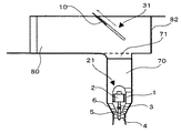
本発明に係る立軸バルブ型水車発電設備の第4の実施形態について図10および図11を用いて以下に説明する。この実施形態は第1の実施形態の変形例であって、第1の実施形態と同一部分または類似部分には、同一符号を付して、重複説明を省略する。図10は、本実施形態の立軸バルブ型水車発電設備であって、斜板10が下方に配置された状態を示す概略側断面図である。図11は、図10における斜板10が上方に配置された状態を示す概略側断面図である。
[Fourth Embodiment]
A fourth embodiment of the vertical shaft type water turbine power generation facility according to the present invention will be described below with reference to FIGS. 10 and 11. This embodiment is a modification of the first embodiment, and the same or similar parts as those of the first embodiment are denoted by the same reference numerals, and redundant description is omitted. FIG. 10 is a schematic cross-sectional side view showing a state where the
本実施形態では、水平流路80の壁面に、斜板上下移動装置31が配置されている。この斜板上下移動装置31は、斜板10が所定の傾きを保持したまま、この傾きに沿って上下方向に移動可能に構成されている。
In the present embodiment, the swash plate
図10では、水車発電機21が運転しているときの斜板10の位置を示しており、第1の実施形態と同様に、空気吸込み渦の発生を抑制することができる。
FIG. 10 shows the position of the
水車発電機21のメンテナンスや交換等の作業をする必要が生じた場合、作業員は、水車発電機21の上方からアクセスする。斜板10が、図10の状態で固定されている場合には、この斜板10が水車発電機21へのアクセスの障害になる場合がある。
When it becomes necessary to perform work such as maintenance or replacement of the
これに対して、斜板上下移動装置31によって、図11に示すように、図10での斜板10の位置から斜板10の傾きを保ちながら上方へ移動することができる。これにより、水車発電機21の上方が開放された状態になるため、作業員が水車発電機21へ容易にアクセスすることができる。また、所定の傾きを保ったまま斜板10が上下に移動できるため、斜板10をメンテナンス前の状態に容易に戻すことができる。
On the other hand, as shown in FIG. 11, the swash plate up-and-down moving
以上の説明からわかるように本実施形態によれば、水車発電機21が稼働しているときは、空気吸込み渦の発生を抑制でき、且つ水車発電機21のメンテナンス等を行うときは、メンテナンス作業をより効率よく行うことが可能になる。
As can be seen from the above description, according to the present embodiment, when the
[第5の実施形態]
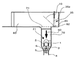
本発明に係る立軸バルブ型水車発電設備の第5の実施形態について図12および図13を用いて以下に説明する。この実施形態は第4の実施形態(図10、図11)の変形例であって、第4の実施形態と同一部分または類似部分には、同一符号を付して、重複説明を省略する。図12は、本実施形態の立軸バルブ型水車発電設備であって、斜板10が終端部82側に配置された状態を示す概略側断面図である。図13は、図12における斜板10が給水口81側に配置された状態を示す概略側断面図である。
[Fifth Embodiment]
A fifth embodiment of the vertical shaft type water turbine power generation facility according to the present invention will be described below with reference to FIGS. 12 and 13. This embodiment is a modification of the fourth embodiment (FIGS. 10 and 11), and the same or similar parts as those of the fourth embodiment are denoted by the same reference numerals, and redundant description is omitted. FIG. 12 is a schematic cross-sectional side view showing a state in which the
本実施形態では、水平流路80の壁面に、斜板水平移動装置32が配置されている。この斜板水平移動装置32は、斜板10が所定の傾きを保持したまま、水平流路80が延びる方向に沿って水平に平行移動可能に構成されている。
In the present embodiment, the swash plate
図12では、水車発電機21が運転しているときの斜板の位置を示しており、第1の実施形態と同様に、空気吸込み渦の発生を抑制することができる。
FIG. 12 shows the position of the swash plate when the
水車発電機のメンテナンスや交換等の作業をする必要が生じた場合、作業員は、水車発電機21の上方からアクセスする。斜板10が図12の状態で固定されている場合には、この斜板10が水車発電機21へのアクセスの障害になる場合がある。
When it becomes necessary to perform maintenance or replacement of the turbine generator, the worker accesses from above the
これに対して、斜板水平移動装置32によって、図13に示すように、斜板10の傾きを保ちながら給水口81に向かって水平に平衡移動することができる。これにより、水車発電機21の上方が開放された状態にすることができる。
On the other hand, the swash plate
以上の説明からわかるように本実施形態によれば、第4の実施形態と同様に効果を得ることが可能となる。 As can be seen from the above description, according to the present embodiment, it is possible to obtain the same effects as in the fourth embodiment.
[第6の実施形態]
本発明に係る立軸バルブ型水車発電設備の第6の実施形態について図14および図15を用いて以下に説明する。この実施形態は第4の実施形態の変形例であって、第4の実施形態(図10、図11)と同一部分または類似部分には、同一符号を付して、重複説明を省略する。図14は、本実施形態の立軸バルブ型水車発電設備であって、分割可能な分割斜板14が閉じた状態を示す概略側断面図である。図15は、図14における分割斜板14が開いた状態を示す概略側断面図である。
[Sixth Embodiment]
A sixth embodiment of the vertical shaft type water turbine power generation facility according to the present invention will be described below with reference to FIGS. 14 and 15. This embodiment is a modification of the fourth embodiment, and the same or similar parts as those in the fourth embodiment (FIGS. 10 and 11) are denoted by the same reference numerals, and redundant description is omitted. FIG. 14 is a schematic sectional side view showing a state where the
本実施形態では、水平流路80の壁面に、分割斜板回動装置33が配置されている。この分割斜板回動装置33は、水平流路80の両側の壁面それぞれに所定の傾きを保ちながら固定された傾斜回動軸41を有している。
In the present embodiment, the divided swash
さらに、本実施形態では、第1〜第5の実施形態で説明した斜板10に代わって、水平流路80が延びる方向に沿って中央で2つに分割可能な分割斜板14を用いている。分割されていない状態の分割斜板14は、第1の実施形態で用いている斜板10と同様の機能を有している。中央で2つに分割可能な分割斜板14それぞれは、水平流路80の両側の壁面に設けられた傾斜回動軸41の周りを回動可能に構成されている。
Furthermore, in this embodiment, instead of the
図14では、水車発電機21が運転しているときの斜板の位置を示しており、第1の実施形態と同様に、空気吸込み渦の発生を抑制することができる。このときの分割斜板14は、上記の斜板10と同じ状態を保持している。
FIG. 14 shows the position of the swash plate when the
水車発電機21のメンテナンスや交換等の作業をする必要が生じた場合、作業員は、水車発電機21の上方からアクセスする。分割斜板14が、図14の状態で固定されている場合には、この分割斜板14が水車発電機21へのアクセスの障害になる場合がある。
When it becomes necessary to perform work such as maintenance or replacement of the
これに対して、2つに分割された分割斜板14それぞれが、傾斜回動軸41の周りを回動して、図15に示すように傾斜回動軸41の周りを回動すると、水車発電機21の上方が開放された状態になる。
On the other hand, when each of the two divided
以上の説明からわかるように本実施形態によれば、第4の実施形態と同様に効果を得ることが可能となる。 As can be seen from the above description, according to the present embodiment, it is possible to obtain the same effects as in the fourth embodiment.
[第7の実施形態]
本発明に係る立軸バルブ型水車発電設備の第7の実施形態について図16および図17を用いて以下に説明する。この実施形態は第4の実施形態(図10、図11)の変形例であって、第4の実施形態と同一部分または類似部分には、同一符号を付して、重複説明を省略する。図16は、本実施形態の立軸バルブ型水車発電設備であって、斜板10が所定の角度を保った状態を示す概略側断面図である。図17は、図16における斜板10の水流を受ける面が鉛直な状態を示す概略側断面図である。
[Seventh Embodiment]
A seventh embodiment of the vertical valve type water turbine power generation facility according to the present invention will be described below with reference to FIGS. 16 and 17. This embodiment is a modification of the fourth embodiment (FIGS. 10 and 11), and the same or similar parts as those of the fourth embodiment are denoted by the same reference numerals, and redundant description is omitted. FIG. 16 is a schematic cross-sectional side view showing a state where the
本実施形態では、開口部71よりも終端部82側の水平流路80の底部に、斜板回動装置35が取り付けられている。この斜板回動装置35は、水平流路80の幅方向に水平に延びて水平流路80の底部に取り付けられた水平回動軸45と、この水平回動軸45周りを回動可能に構成された回動板35aを有する。
In the present embodiment, the swash
さらに、斜板10の終端部側端辺10aが、回動板35aの水平回動軸45と遠い方の端辺に平行に取り付けられている。
Further, the end
本実施形態の斜板10は、水平回動軸45周りを回動可能に構成されている。水車発電機21のメンテナンス等を行うときは、斜板10を回動させて、斜板10の面が鉛直になるように固定する。これにより、水車発電機21の上方を開放された状態になる。
The
以上の説明からわかるように本実施形態によれば、第4の実施形態と同様に効果を得ることが可能となる。 As can be seen from the above description, according to the present embodiment, it is possible to obtain the same effects as in the fourth embodiment.
[第8の実施形態]
本発明に係る立軸バルブ型水車発電設備の第8の実施形態について図18および図19を用いて以下に説明する。この実施形態は第2の実施形態(図3、図4)の変形例であって、第2の実施形態と同一部分または類似部分には、同一符号を付して、重複説明を省略する。図18は、本実施形態の立軸バルブ型水車発電設備を示す概略平面図である。図19は、図18の概略側断面図である。
[Eighth Embodiment]
An eighth embodiment of an upright valve type turbine power generation facility according to the present invention will be described below with reference to FIGS. 18 and 19. This embodiment is a modification of the second embodiment (FIGS. 3 and 4), and the same or similar parts as those of the second embodiment are denoted by the same reference numerals, and redundant description is omitted. FIG. 18 is a schematic plan view showing the vertical shaft valve-type turbine power generation facility of the present embodiment. FIG. 19 is a schematic sectional side view of FIG.
本実施形態では、2つの小斜板、すなわち第1小斜板12a、第2小斜板12bを有する。これらの小斜板12a、12bは、水平流路80の両側の壁面それぞれに1つずつ取り付けられている。
In the present embodiment, there are two small swash plates, that is, a first small
これら第1および第2小斜板12a、12bそれぞれの水平流路幅方向をb1して、水平流路80の給水口81側の幅をB、開口部直径をD0とすると、第1および第2小斜板12a、12bは、上記b1が式(7)を満たすように構成されている。
When the horizontal flow path width direction of each of the first and second
b1≦(B―D0)/2 …(7)
すなわち、開口部71の上方の自由水面20は、大気開放された状態になっている。
b1 ≦ (B−D0) / 2 (7)
That is, the
また、これらの第1および第2小斜板12a、12bそれぞれは、第2の実施形態と同様に、角度α、水没深さh、水平方向距離ΔXが定められている。
In addition, each of the first and second
本実施形態によれば、第2の実施形態と同様の効果を得ることが可能であるとともに、開口部71の上方には障害物がなく開放されているため、水車発電機21のメンテナンス等を行うときは、水車発電機21の上方からのアクセスが容易になる。
According to the present embodiment, it is possible to obtain the same effect as that of the second embodiment, and since there is no obstacle above the
[第9の実施形態]
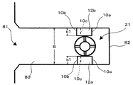
本発明に係る立軸バルブ型水車発電設備の第9の実施形態について図20および図21を用いて以下に説明する。この実施形態は第8の実施形態の変形例であって、第8の実施形態と同一部分または類似部分には、同一符号を付して、重複説明を省略する。図20は、本実施形態の立軸バルブ型水車発電設備を示す概略平面図である。図21は、図20の概略側断面図である。
[Ninth Embodiment]
A ninth embodiment of the vertical shaft type water turbine power generation facility according to the present invention will be described below with reference to FIGS. 20 and 21. FIG. This embodiment is a modification of the eighth embodiment, and the same or similar parts as those of the eighth embodiment are denoted by the same reference numerals, and redundant description is omitted. FIG. 20 is a schematic plan view showing an upright valve type water turbine power generation facility of the present embodiment. 21 is a schematic sectional side view of FIG.
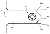
本実施形態では、開口部71の上方の水平流路80の両側の壁面それぞれには、終端部82側が下がるように、且つ自由水面20に対して所定の傾きを有しながら水流を受ける傾斜面13が形成されている。
In the present embodiment, each of the wall surfaces on both sides of the
開口部71よりも給水口81側の水平流路80の幅をB、開口部71よりも終端部82側の水平流路80の幅をCとして、各傾斜面13の水平流路幅方向をb2とすると、傾斜面13は、上記b2が式(8)を満たすように構成される。
The width of the
b2=(B−C)/2 …(8)
また、各傾斜面13と自由水面20とのなす角度αは、第2の実施形態と同様に、式(1)を満たすように形成されている。
b2 = (BC) / 2 (8)
Further, the angle α formed by each
また、第8の実施形態と同様に、各傾斜面13と自由水面20とが交わってなる交線を水平幅方向交線10cとして、開口部71の中心と水平幅方向交線10cとの水平方向距離をΔXとすると、ΔX/D0は、式(3)を満たすように構成されている。
Similarly to the eighth embodiment, an intersection line between each
本実施形態によれば、第8の実施形態と同様の効果を得ることが可能であるとともに、流路が固定されているため耐久性を向上させることができる。 According to the present embodiment, it is possible to obtain the same effect as that of the eighth embodiment, and it is possible to improve durability because the flow path is fixed.
[第10の実施形態]
本発明に係る立軸バルブ型水車発電設備の第10の実施形態について図22および図23を用いて以下に説明する。この実施形態は第1の実施形態の変形例であって、第1の実施形態と同一部分または類似部分には、同一符号を付して、重複説明を省略する。図22は、本実施形態の立軸バルブ型水車発電設備を示す概略平面図である。図23は、図22の概略側断面図である。
[Tenth embodiment]
A tenth embodiment of a vertical shaft type water turbine power generation facility according to the present invention will be described below with reference to FIGS. 22 and 23. This embodiment is a modification of the first embodiment, and the same or similar parts as those of the first embodiment are denoted by the same reference numerals, and redundant description is omitted. FIG. 22 is a schematic plan view showing the vertical shaft type water turbine power generation facility of the present embodiment. FIG. 23 is a schematic sectional side view of FIG.
本実施形態では、水平流路80底部から上方に延びた平板状の3つの第1隔壁27a、第2隔壁27b、および第3隔壁27cが、開口部71の中心よりも終端部82側に配列されている。
In the present embodiment, three flat
水平流路80の一方の壁面に第1隔壁27aが取り付けられて、もう一方の壁面に第3隔壁27cが取り付けられている。第2隔壁27bは、第1隔壁27aと第3隔壁27cとを連結するように配置されている。すなわち、3枚の隔壁27a、27b、27cによって、開口部71の終端部82側の外側半周を囲うように配置されて、且つ水平流路80を開口部71が形成された側と終端部82側とを隔てるように構成されている。
The
さらに、第1隔壁27aと第2隔壁27bとの連結部と、終端部82とを連結するように、第4隔壁27dが設けられている。同様に、第3隔壁27cと第2隔壁27bとの連結部と、終端部82とを連結するように、第5隔壁27eが設けられている。
Further, a
これらの隔壁27a、27b、27c、27d、27eは、水流に対して所定の抵抗力を作用させながら水が流通可能に構成されて、例えば、例えばパンチングメタルや穴あきコンクリート等の多孔質部材により形成されている。
These
水車発電機21を運転するときに、水平流路80を給水口81から終端部82に向かって流れる水の一部は、終端部82に向かって開口部71の上方を通り過ぎる。
When the
終端部82付近の水は、第1隔壁27a、第2隔壁27b、および第3隔壁27cを流通することによって、流速が小さくなり整流される。
The water in the vicinity of the
流速が小さくなり整流された状態で、終端部82に達するため、循環流の発生を抑制することができる。このとき、終端部82近傍の水は、第4および第5隔壁27d、27eを流通するため、より整流効果をより高めることができる。
Since it reaches the
第1〜第3隔壁27a、27b、27cよりも終端部82側の水面は、安定しているため、終端部82付近での渦の発生が抑制される。このため、空気吸込み渦の発生が抑制可能になるため、水車発電機21を安定して運転することができる。したがって、エネルギ損失を抑制し効率的に水車発電機を運転することが可能になる。
Since the water surface closer to the
[第11の実施形態]
本発明に係る立軸バルブ型水車発電設備の第11の実施形態について図24および図25を用いて以下に説明する。この実施形態は第10の実施形態の変形例であって、第10の実施形態と同一部分または類似部分には、同一符号を付して、重複説明を省略する。図24は、本実施形態の立軸バルブ型水車発電設備を示す概略平面図である。図25は、図24の概略側断面図である。
[Eleventh embodiment]
An eleventh embodiment of the vertical valve type water turbine power generation facility according to the present invention will be described below with reference to FIGS. 24 and 25. This embodiment is a modification of the tenth embodiment, and the same reference numerals are given to the same or similar parts as those of the tenth embodiment, and the duplicate description is omitted. FIG. 24 is a schematic plan view showing an upright valve type water turbine power generation facility of the present embodiment. 25 is a schematic sectional side view of FIG.
本実施形態では、2つの隅隔壁、すなわち第1隅隔壁28a、第2隅隔壁28bを有する。これらの第1および第2隅隔壁28a、28bそれぞれは、開口部71よりも終端部82側で、水平流路80の両側の壁面それぞれと終端部82とで形成された2つの隅部83それぞれを、水平方向から覆うように配置されている。これらの第1および第2隅隔壁28a、28bの材質等は、第10の実施形態で説明した第1〜第5隔壁27a〜27eと同様である。
In the present embodiment, there are two corner partition walls, that is, a first
水車発電機21を運転するときに、水平流路80を給水口81から終端部82に向かって流れる水の一部は、開口部71の上方を通り過ぎて終端部82に向かう。終端部82に到達した水は、左右に分かれて第1隅隔壁28aおよび第2隅隔壁28bを流通することによって、流速が小さくなり整流される。このため、循環流の発生を抑制することができる。
When the
終端部82側の水面が安定しているため、第10の実施形態と同様に、終端部82付近での渦の発生が抑制される。このため、空気吸込み渦の発生が抑制可能となり、水車発電機21を安定して運転することができる。したがって、エネルギ損失を抑制し効率的に水車発電機を運転すること可能になる。
Since the water surface on the
[その他の実施形態]
上記実施形態の説明は、本発明を説明するための例示であって、特許請求の範囲に記載の発明を限定するものではない。また、本発明の各部構成は上記実施形態に限らず、特許請求の範囲に記載の技術的範囲内で種々の変形が可能である。
[Other Embodiments]
The description of the above embodiment is an example for explaining the present invention, and does not limit the invention described in the claims. Moreover, each part structure of this invention is not restricted to the said embodiment, A various deformation | transformation is possible within the technical scope as described in a claim.
例えば、第3の実施形態の格子斜板11を第2の実施形態に用いてもよい。また、第4〜第7の実施形態の特徴と、第2の実施形態の特徴を組み合わせてもよい。
For example, the
さらに、第10および第11の実施形態の特徴に第1の実施形態の特徴を組み合わせることも可能である。 Further, the features of the first embodiment can be combined with the features of the tenth and eleventh embodiments.
1…バルブ、2…発電機、3…主軸、4…ランナ、5…ガイドベーン、6…ステー、
10…斜板、10a…終端部側端辺、10b…給水口側端辺、10c…水平幅方向交線、
11…格子斜板、11a…格子板、12a…第1小斜板、12b…第2小斜板、13…傾斜面、14…分割斜板、20…自由水面、21…水車発電機、27a…第1隔壁、27b…第2隔壁、27c…第3隔壁、27d…第4隔壁、27e…第5隔壁、28a…第1隅隔壁、28b…第2隅隔壁、31…斜板上下移動装置、32…斜板水平移動装置、33…分割斜板回動装置、35…斜板回動装置、35a…回動板、41…傾斜回動軸、45…水平回動軸、70…縦方向流路、71…開口部、80…水平流路、81…給水口、82…終端部、83…隅部
1 ... Valve, 2 ... Generator, 3 ... Main shaft, 4 ... Runner, 5 ... Guide vane, 6 ... Stay,
DESCRIPTION OF
DESCRIPTION OF
Claims (13)
前記水車に接続されてその水車によって駆動される発電機と、
自由水面が形成されて給水口から終端部近くの前記水車の上方に向かってほぼ水平に水が流れるように形成された水平流路と、
前記水平流路の底部の前記終端部寄りに形成された開口部から前記発電機に向かって下向きに延びて、前記水平流路を流通した水が前記水車に向かって下向きに流れるように形成された縦方向流路と、
前記開口部の上方の前記自由水面近傍に配置されて、前記終端部側が下がるように前記自由水面に対して所定の傾きを保ち、前記終端部側が前記自由水面下にあるように配置された斜板と、
を有することを特徴とする立軸バルブ型水車発電設備。 A water turbine arranged such that the rotation axis faces the vertical direction;
A generator connected to and driven by the water wheel;
A horizontal flow path formed such that a free water surface is formed and water flows substantially horizontally from the water supply port toward the upper part of the water wheel near the terminal end,
From the opening formed near the terminal end of the bottom of the horizontal flow path, it extends downward toward the generator, and is formed such that water flowing through the horizontal flow path flows downward toward the water turbine. A longitudinal flow path,
The slant is disposed near the free water surface above the opening, maintains a predetermined inclination with respect to the free water surface so that the terminal end side is lowered, and is disposed so that the terminal end side is below the free water surface. The board,
A vertical shaft type water turbine power generation facility characterized by comprising:
前記斜板は、前記水平流路が延びる方向に沿って2つに分割可能に形成されて、2つに分割された前記斜板それぞれは、前記各傾斜回動軸の周りを回動可能に構成されていることを特徴とする請求項1に記載の立軸バルブ型水車発電設備。 An inclined rotation axis arranged to maintain the predetermined inclination on each wall surface of the horizontal flow path;
The swash plate is formed so as to be divided into two along the direction in which the horizontal flow path extends, and each of the swash plates divided into two can turn around the respective tilt rotation shafts. It is comprised, The vertical axis | shaft valve-type water turbine power generation equipment of Claim 1 characterized by the above-mentioned.
前記斜板は、前記水平回動軸周りに回動可能に構成されていることを特徴とする請求項1に記載の立軸バルブ型水車発電設備。 A horizontal rotation shaft disposed at the bottom of the horizontal flow path on the terminal end side of the opening and extending horizontally in the width direction of the horizontal flow path;
The vertical shaft valve-type water turbine power generation facility according to claim 1, wherein the swash plate is configured to be rotatable around the horizontal rotation axis.
前記水車に接続されてその水車によって駆動される発電機と、
自由水面が形成されて給水口から終端部近くの前記水車の上方に向かってほぼ一定の幅でほぼ水平に水が流れるように形成された水平流路と、
前記水平流路の底部の前記終端部寄りに形成された開口部から前記発電機に向かって下向きに延びて、前記水平流路を流通した水が前記水車に向かって下向きに流れるように形成された縦方向流路と、
それぞれが前記開口部の上方で前記水平流路の両側の壁面それぞれに取り付けられて前記終端部側が前記自由水面下にあるように且つ前記終端部側が下がるように前記自由水面に対して所定の傾きを保つように配置されて、前記開口部の上方が開放されるように構成された斜板と、
を有することを特徴とする立軸バルブ型水車発電設備。 A water turbine arranged such that the rotation axis faces the vertical direction;
A generator connected to and driven by the water wheel;
A horizontal flow path formed such that a free water surface is formed and water flows substantially horizontally with a substantially constant width from the water supply port toward the upper part of the water wheel near the terminal end;
From the opening formed near the terminal end of the bottom of the horizontal flow path, it extends downward toward the generator, and is formed such that water flowing through the horizontal flow path flows downward toward the water turbine. A longitudinal flow path,
A predetermined inclination with respect to the free water surface so that the end portion side is below the free water surface and the end portion side is lowered so that each is attached to the respective wall surfaces on both sides of the horizontal flow path above the opening. A swash plate that is arranged so as to maintain an upper portion of the opening,
A vertical shaft type water turbine power generation facility characterized by comprising:
h/D0≧0.15を満たすように構成されていることを特徴とする請求項1ないし請求項7のいずれか一項に記載の立軸バルブ型水車発電設備。 The opening is circular, the diameter of the opening is D0, the water level from the end of the swash plate to the free water surface is h, and the water level in the horizontal channel is the lowest water level. When
8. The vertical shaft valve-type water turbine power generation facility according to any one of claims 1 to 7, wherein h / D0 ≧ 0.15 is satisfied.
前記斜板と前記自由水面とが交わってなる水平方向交線と、前記開口部の中心との水平方向距離をΔXとしたときに、
ΔX/D0は、
前記水平方向交線が前記開口部の中心よりも前記給水口側のときは、0より大きくて且つ0.3以下となり、
前記水平方向交線が前記開口部の中心よりも前記終端部側のときは、0より大きくて且つ0.2以下となるように構成されていること、
を特徴とする請求項1ないし請求項8のいずれか一項に記載の立軸バルブ型水車発電設備。 The opening is circular, and the diameter of the opening is D0,
When the horizontal distance between the swash plate and the horizontal intersecting line formed by the free water surface and the center of the opening is ΔX,
ΔX / D0 is
When the horizontal crossing line is closer to the water supply port than the center of the opening, it is greater than 0 and less than or equal to 0.3.
When the horizontal crossing line is closer to the terminal end side than the center of the opening, it is configured to be larger than 0 and equal to or less than 0.2.
The vertical shaft valve-type water turbine power generation facility according to any one of claims 1 to 8, characterized in that:
前記水車に接続されてその水車によって駆動される発電機と、
自由水面が形成されて給水口から終端部近くの前記水車の上方に向かってほぼ水平に水が流れるように形成されて、前記給水口から前記開口部の前記給水口側端部までほぼ一定の幅になるように形成された水平流路と、
前記水平流路の底部の前記終端部寄りに形成された円形の開口部から前記発電機に向かって下向きに延びて、前記水平流路を流通した水が前記水車に向かって下向きに流れるように形成された縦方向流路と、
を有し、
前記開口部の上方の前記水平流路の両側の壁面それぞれには、前記終端部側が下がるように且つ前記自由水面に対して所定の傾きを有し前記開口部の上方が開放されるように構成された傾斜面が形成されていること、
を特徴とする立軸バルブ型水車発電設備。 A water turbine arranged such that the rotation axis faces the vertical direction;
A generator connected to and driven by the water wheel;
A free water surface is formed so that water flows substantially horizontally from the water supply port toward the upper part of the water wheel near the terminal end, and is substantially constant from the water supply port to the water supply port side end of the opening. A horizontal channel formed to have a width;
Extending downward from the circular opening formed near the end portion of the bottom of the horizontal flow path toward the generator, so that water flowing through the horizontal flow path flows downward toward the water turbine. A formed longitudinal flow path;
Have
Each wall surface on both sides of the horizontal flow path above the opening is configured such that the end portion side is lowered and has a predetermined inclination with respect to the free water surface, and the upper portion of the opening is opened. An inclined surface is formed,
Vertical shaft type water turbine power generation equipment characterized by
前記水車に接続されてその水車によって駆動される発電機と、
自由水面が形成されて給水口から終端部近くの前記水車の上方に向かってほぼ水平に水が流れるように形成された水平流路と、
前記水平流路の底部の前記終端部寄りに形成された開口部から前記発電機に向かって下向きに延びて、前記水平流路を流通した水が前記水車に向かって下向きに流れるように形成された縦方向流路と、
前記水平流路底部から上方に延びて、前記開口部よりも前記終端部側で、前記水平流路の両側の壁面それぞれと前記終端部とからなる隅部それぞれを水平方向から覆うように配置された多孔質部材の隔壁と、
を有することを特徴とする立軸バルブ型水車発電設備。 A water turbine arranged such that the rotation axis faces the vertical direction;
A generator connected to and driven by the water wheel;
A horizontal flow path formed such that a free water surface is formed and water flows substantially horizontally from the water supply port toward the upper part of the water wheel near the terminal end,
From the opening formed near the terminal end of the bottom of the horizontal flow path, it extends downward toward the generator, and is formed such that water flowing through the horizontal flow path flows downward toward the water turbine. A longitudinal flow path,
It extends upward from the bottom of the horizontal flow path and is disposed so as to cover each of the corners formed by the wall surfaces on both sides of the horizontal flow path and the terminal end from the horizontal direction on the terminal end side of the opening. Porous partition walls,
A vertical shaft type water turbine power generation facility characterized by comprising:
Priority Applications (1)
| Application Number | Priority Date | Filing Date | Title |
|---|---|---|---|
| JP2008262119A JP5058118B2 (en) | 2008-10-08 | 2008-10-08 | Vertical shaft type water turbine power generation equipment |
Applications Claiming Priority (1)
| Application Number | Priority Date | Filing Date | Title |
|---|---|---|---|
| JP2008262119A JP5058118B2 (en) | 2008-10-08 | 2008-10-08 | Vertical shaft type water turbine power generation equipment |
Publications (2)
| Publication Number | Publication Date |
|---|---|
| JP2010090822A true JP2010090822A (en) | 2010-04-22 |
| JP5058118B2 JP5058118B2 (en) | 2012-10-24 |
Family
ID=42253785
Family Applications (1)
| Application Number | Title | Priority Date | Filing Date |
|---|---|---|---|
| JP2008262119A Active JP5058118B2 (en) | 2008-10-08 | 2008-10-08 | Vertical shaft type water turbine power generation equipment |
Country Status (1)
| Country | Link |
|---|---|
| JP (1) | JP5058118B2 (en) |
Cited By (3)
| Publication number | Priority date | Publication date | Assignee | Title |
|---|---|---|---|---|
| CN112412683A (en) * | 2020-12-17 | 2021-02-26 | 东方电气集团东方电机有限公司 | Water turbine center gulp valve reset by self weight |
| CN113175406A (en) * | 2021-04-23 | 2021-07-27 | 西北农林科技大学 | Parent fish type through-flow turbine |
| CN116123148A (en) * | 2023-02-20 | 2023-05-16 | 扬州大学 | Novel bulb body structure with regular pits on surface based on energy conservation and noise reduction |
Citations (4)
| Publication number | Priority date | Publication date | Assignee | Title |
|---|---|---|---|---|
| JP2005163563A (en) * | 2003-11-28 | 2005-06-23 | Toshiba Corp | Vertical shaft valve type hydraulic power generation equipment |
| JP2007120461A (en) * | 2005-10-31 | 2007-05-17 | Toshiba Corp | Vertical shaft valve type hydraulic power generation equipment |
| JP2008180092A (en) * | 2007-01-23 | 2008-08-07 | Toshiba Corp | Vertical shaft valve type hydraulic turbine power generation facility, and its operation control method |
| JP2009235951A (en) * | 2008-03-26 | 2009-10-15 | Toshiba Corp | Vertical shaft valve type hydraulic turbine generator |
-
2008
- 2008-10-08 JP JP2008262119A patent/JP5058118B2/en active Active
Patent Citations (4)
| Publication number | Priority date | Publication date | Assignee | Title |
|---|---|---|---|---|
| JP2005163563A (en) * | 2003-11-28 | 2005-06-23 | Toshiba Corp | Vertical shaft valve type hydraulic power generation equipment |
| JP2007120461A (en) * | 2005-10-31 | 2007-05-17 | Toshiba Corp | Vertical shaft valve type hydraulic power generation equipment |
| JP2008180092A (en) * | 2007-01-23 | 2008-08-07 | Toshiba Corp | Vertical shaft valve type hydraulic turbine power generation facility, and its operation control method |
| JP2009235951A (en) * | 2008-03-26 | 2009-10-15 | Toshiba Corp | Vertical shaft valve type hydraulic turbine generator |
Cited By (4)
| Publication number | Priority date | Publication date | Assignee | Title |
|---|---|---|---|---|
| CN112412683A (en) * | 2020-12-17 | 2021-02-26 | 东方电气集团东方电机有限公司 | Water turbine center gulp valve reset by self weight |
| CN113175406A (en) * | 2021-04-23 | 2021-07-27 | 西北农林科技大学 | Parent fish type through-flow turbine |
| CN116123148A (en) * | 2023-02-20 | 2023-05-16 | 扬州大学 | Novel bulb body structure with regular pits on surface based on energy conservation and noise reduction |
| CN116123148B (en) * | 2023-02-20 | 2023-09-29 | 扬州大学 | Novel bulb body structure with regular pits on surface based on energy conservation and noise reduction |
Also Published As
| Publication number | Publication date |
|---|---|
| JP5058118B2 (en) | 2012-10-24 |
Similar Documents
| Publication | Publication Date | Title |
|---|---|---|
| KR101333762B1 (en) | Water turbine with bi-symmetric airfoil | |
| Choi et al. | Performance and internal flow characteristics of a cross-flow hydro turbine by the shapes of nozzle and runner blade | |
| US9234524B2 (en) | Boundary layer controlled logarithmic spiral blade | |
| CN101255850A (en) | Wind power generation system | |
| JP2010249120A (en) | Vortex prevention device and pump device | |
| CN109406099B (en) | Low-turbulence compact circulating water tunnel experimental device | |
| JP5025273B2 (en) | Pump device and pump gate device | |
| JP5058118B2 (en) | Vertical shaft type water turbine power generation equipment | |
| JP2008180130A (en) | Axial flow water turbine and its operation method | |
| KR20140136382A (en) | Pull-out type vertical pump | |
| KR20160039226A (en) | An assembly for generating electricity | |
| JP2007120461A (en) | Vertical shaft valve type hydraulic power generation equipment | |
| CN102720622B (en) | Vortex generator for turbine draft tube | |
| Lillahulhaq et al. | Unsteady simulations of Savonius and Icewind turbine blade design using fluid-structure interaction method | |
| JP4776333B2 (en) | Hydraulic machine guide vane and hydraulic machine equipped with the guide vane | |
| JP2009235951A (en) | Vertical shaft valve type hydraulic turbine generator | |
| CN102401135B (en) | Fluid machinery | |
| JP4846139B2 (en) | Hydraulic machine | |
| JP2009036114A (en) | Vertical shaft valve type hydraulic turbine generator set | |
| CN219795658U (en) | Flow guiding structure of box-type fan and box-type fan | |
| JP4876797B2 (en) | Hydraulic machinery and hydraulic machinery staying | |
| Kyzyrov et al. | Performance Enhancement of a Centrifugal Pump by Impeller Retrofitting | |
| KR102031614B1 (en) | Turbine in water pipe line with reinforced airfoil blade | |
| KR102337146B1 (en) | Micro hydro power generation apparatus | |
| CN113818550B (en) | Pump station |
Legal Events
| Date | Code | Title | Description |
|---|---|---|---|
| A621 | Written request for application examination |
Free format text: JAPANESE INTERMEDIATE CODE: A621 Effective date: 20110128 |
|
| RD04 | Notification of resignation of power of attorney |
Free format text: JAPANESE INTERMEDIATE CODE: A7424 Effective date: 20110420 |
|
| TRDD | Decision of grant or rejection written | ||
| A977 | Report on retrieval |
Free format text: JAPANESE INTERMEDIATE CODE: A971007 Effective date: 20120629 |
|
| A01 | Written decision to grant a patent or to grant a registration (utility model) |
Free format text: JAPANESE INTERMEDIATE CODE: A01 Effective date: 20120703 |
|
| A01 | Written decision to grant a patent or to grant a registration (utility model) |
Free format text: JAPANESE INTERMEDIATE CODE: A01 |
|
| A61 | First payment of annual fees (during grant procedure) |
Free format text: JAPANESE INTERMEDIATE CODE: A61 Effective date: 20120731 |
|
| FPAY | Renewal fee payment (event date is renewal date of database) |
Free format text: PAYMENT UNTIL: 20150810 Year of fee payment: 3 |
|
| R151 | Written notification of patent or utility model registration |
Ref document number: 5058118 Country of ref document: JP Free format text: JAPANESE INTERMEDIATE CODE: R151 |
|
| FPAY | Renewal fee payment (event date is renewal date of database) |
Free format text: PAYMENT UNTIL: 20150810 Year of fee payment: 3 |