JP2010090574A - Structure and method for anchoring reinforcement to reinforced concrete structure - Google Patents
Structure and method for anchoring reinforcement to reinforced concrete structure Download PDFInfo
- Publication number
- JP2010090574A JP2010090574A JP2008260212A JP2008260212A JP2010090574A JP 2010090574 A JP2010090574 A JP 2010090574A JP 2008260212 A JP2008260212 A JP 2008260212A JP 2008260212 A JP2008260212 A JP 2008260212A JP 2010090574 A JP2010090574 A JP 2010090574A
- Authority
- JP
- Japan
- Prior art keywords
- reinforcing bar
- reinforced concrete
- fixing
- connecting member
- concrete structure
- Prior art date
- Legal status (The legal status is an assumption and is not a legal conclusion. Google has not performed a legal analysis and makes no representation as to the accuracy of the status listed.)
- Granted
Links
Images

Landscapes
- Reinforcement Elements For Buildings (AREA)
- Working Measures On Existing Buildindgs (AREA)
Abstract
Description
本発明は、鉄筋コンクリート構造物に対して鉄筋を定着させるための構造及び方法に関するものであり、特に、既設コンクリート構造物の補強工事に適した鉄筋の定着構造及び定着方法に関するものである。 The present invention relates to a structure and a method for fixing a reinforcing bar to a reinforced concrete structure, and more particularly to a reinforcing bar fixing structure and a fixing method suitable for reinforcement work of an existing concrete structure.
近年、大規模地震の発生が懸念される中、既設の鉄筋コンクリート構造物に対する耐震補強のニーズが高まっている。既設の鉄筋コンクリート構造物のせん断耐荷力が不足する場合には、主鉄筋と交差する方向に補強鋼材を追加することで、構造物のせん断耐荷力を増加させなければならない。このような補強工事では、補強部材が確実に定着することが必要であると共に、既設構造物の損傷を最小限とし、さらに容易に施工できることが要求される。 In recent years, there is a growing need for seismic reinforcement for existing reinforced concrete structures in the face of concerns about the occurrence of large-scale earthquakes. When the existing reinforced concrete structure has insufficient shear load capacity, it is necessary to increase the shear load capacity of the structure by adding a reinforcing steel material in a direction crossing the main reinforcing bar. In such a reinforcement work, it is necessary that the reinforcing member is firmly fixed, and it is required that the existing structure is minimized and can be easily constructed.
従来の一般的な定着構造は、半円形のフックを構造物中に埋め込むようになっている。しかし、このような半円形フック構造は、補強工事において構造物に設けられた挿入孔内に挿入することが困難であった。そこで、既設の鉄筋コンクリート構造物への鉄筋の定着構造が種々提案されている。 In the conventional general fixing structure, a semicircular hook is embedded in the structure. However, it has been difficult to insert such a semicircular hook structure into an insertion hole provided in the structure during reinforcement work. Therefore, various structures for fixing reinforcing bars to existing reinforced concrete structures have been proposed.
例えば、せん断力が作用する既設の鉄筋コンクリート構造物に対して、所定の引抜剛性を確保するための技術が開示されている(特許文献1参照)。この特許文献1に記載された技術は、既設の鉄筋コンクリート構造物の中間壁を貫通してせん断補強部材を設置するための補強部材挿入孔を穿孔する工程と、この補強部材挿入孔に充填材を充填する工程と、せん断補強鉄筋と、その基端部に設けられている基端プレートヘッドとを補強部材挿入孔に挿入して、せん断補強鉄筋の先端部に先端プレートヘッドを固定することにより、中間壁の内部にせん断補強部材を配置する工程とを含んでいる。また、この技術は、せん断補強鉄筋の先端に、鉄筋径の2.5倍以上の直径を有する定着体(先端プレートヘッド)を溶接や摩擦圧接、高周波加熱などを用いて取り付けるようになっている。 For example, a technique for ensuring a predetermined pulling rigidity is disclosed for an existing reinforced concrete structure on which a shearing force acts (see Patent Document 1). The technique described in Patent Document 1 includes a step of drilling a reinforcing member insertion hole for installing a shear reinforcing member through an intermediate wall of an existing reinforced concrete structure, and a filler in the reinforcing member insertion hole. By inserting the step of filling, the shear reinforcing bar and the base plate head provided at the base end thereof into the reinforcing member insertion hole, and fixing the tip plate head to the tip of the shear reinforcing bar, Disposing a shear reinforcement member inside the intermediate wall. In this technique, a fixing body (tip plate head) having a diameter of 2.5 times or more the diameter of the reinforcing bar is attached to the tip of the shear reinforcing reinforcing bar by welding, friction welding, high frequency heating or the like. .
しかし、従来の半円形フック構造からなる定着構造は、半円形フックを有しているため、補強工事において構造物に設けられた挿入孔内に半円形フックを挿入できない場合があり、耐震補強工事への適用が難しい。また、新設工事においても、半円形フック構造では、定着部分の配筋が複雑となるばかりでなく、直交する鉄筋に半円形フックを引っ掛ける場合に施工が難しいという問題があった。 However, since the fixing structure consisting of the conventional semicircular hook structure has a semicircular hook, the semicircular hook may not be inserted into the insertion hole provided in the structure during the reinforcement work. Difficult to apply to In addition, in the new construction, the semicircular hook structure has a problem that not only the fixing of the fixing portion is complicated, but also the construction is difficult when the semicircular hook is hooked on the orthogonal reinforcing bars.
特許文献1に記載された従来技術は、鉄筋径の2.5倍以上の直径を有する定着体(先端プレートヘッド)を用いているため、定着体の分だけ穿孔径が大きくなり、構造物に与える損傷が大きくなると共に、充填材の使用量も多くなり、施工費用が増大する。 The prior art described in Patent Document 1 uses a fixing body (tip plate head) having a diameter of 2.5 times or more the diameter of the reinforcing bar, and therefore the perforation diameter is increased by the amount of the fixing body. As damage is increased, the amount of filler used increases, and construction costs increase.
本発明は、上述した種々の問題点を解決するために提案されたもので、半円形フックを適用できない箇所であっても適用することができ、また、機械式定着と比較して穿孔径が小さく、構造物の損傷を最小限に抑えることができ、さらに、充填材の使用量を低減することが可能な鉄筋コンクリート構造物への鉄筋の定着構造及び定着方法を提供することを目的とする。 The present invention has been proposed in order to solve the various problems described above, and can be applied even in a place where a semicircular hook cannot be applied. An object of the present invention is to provide a fixing structure and a fixing method of a reinforcing bar to a reinforced concrete structure that is small, can minimize damage to the structure, and can reduce the amount of filler used.
本発明に係る鉄筋コンクリート構造物への鉄筋の定着構造及び定着方法は、上述した目的を達成するため、以下の特徴点を有している。
すなわち、本発明に係る鉄筋コンクリート構造物への鉄筋の定着構造は、略平行に配置した一組の鉄筋と、各鉄筋の端部に取り付けて各鉄筋を一体に連結する連結部材とを備えている。そして、連結部材は、連結する各鉄筋にそれぞれ相対する接続部と、各接続部の間に掛け渡す本体部とからなることを特徴とするものである。
In order to achieve the above-mentioned object, the fixing structure and fixing method for reinforcing bars to a reinforced concrete structure according to the present invention have the following features.
That is, the fixing structure of the reinforcing bar to the reinforced concrete structure according to the present invention includes a pair of reinforcing bars arranged substantially in parallel and a connecting member that is attached to an end of each reinforcing bar and integrally connects the reinforcing bars. . And a connection member consists of a connection part respectively opposed to each rebar to connect, and a main-body part spanned between each connection part, It is characterized by the above-mentioned.
また、上述した構成に加えて、鉄筋は、端部を塑性硬化させた後に先細り状に切削加工して形成したテーパーネジ部を有し、連結部材の接続部は、鉄筋の端部に形成したテーパーネジ部に螺着する雌ネジ部を有することが好ましい。 Further, in addition to the above-described configuration, the reinforcing bar has a tapered screw portion formed by cutting into a taper shape after the end portion is plastic-cured, and the connecting portion of the connecting member is formed at the end portion of the reinforcing bar. It is preferable to have a female screw portion that is screwed onto the taper screw portion.
また、本発明に係る鉄筋コンクリート構造物への鉄筋の定着方法は、鉄筋コンクリート構造物に対して、鉄筋及び定着体を挿入するための挿入孔を形成する工程と、鉄筋及び連結部材を挿入孔内に挿入する工程と、挿入孔内への鉄筋及び連結部材の挿入前あるいは挿入後のいずれかの時点で、挿入孔内に充填材を注入すると共に、鉄筋の端部に連結部材を接続する工程と、を含んでいる。そして、鉄筋は、略平行に配置された一組からなり、連結部材は、各鉄筋の端部に取り付けて各鉄筋を一体に連結する連結部材を備え、連結部材は、連結する各鉄筋にそれぞれ相対する接続部と、各接続部の間に掛け渡す本体部とからなることを特徴とするものである。 The method of fixing a reinforcing bar to a reinforced concrete structure according to the present invention includes a step of forming an insertion hole for inserting a reinforcing bar and a fixing body in the reinforced concrete structure, and the reinforcing bar and a connecting member in the insertion hole. And a step of injecting a filler into the insertion hole at any time before or after insertion of the reinforcing bar and the connecting member into the insertion hole and connecting the connecting member to the end of the reinforcing bar. , Including. The reinforcing bars are composed of a pair arranged substantially in parallel, and the connecting member includes connecting members that are attached to the ends of the reinforcing bars and integrally connect the reinforcing bars, and the connecting members are respectively connected to the reinforcing bars to be connected. It consists of an opposing connection part and a main-body part spanned between each connection part.
また、上述した鉄筋コンクリート構造物への鉄筋の定着方法において、挿入孔は、各鉄筋の外径にそれぞれ対応して別個に形成することが可能である。 Moreover, in the fixing method of the reinforcing bar to the above-mentioned reinforced concrete structure, the insertion hole can be formed separately corresponding to the outer diameter of each reinforcing bar.
本発明の鉄筋コンクリート構造物への鉄筋の定着構造及び定着方法によれば、一組の鉄筋と、鉄筋とは別体として形成された連結部材とを用いているため、挿入孔内に鉄筋を挿入した後に、鉄筋の端部に連結部材を連結することにより、半円形フックを適用できない箇所であっても鉄筋の定着を行うことが可能となる。 According to the fixing structure and fixing method of a reinforcing bar to a reinforced concrete structure according to the present invention, since a pair of reinforcing bars and a connecting member formed separately from the reinforcing bars are used, the reinforcing bars are inserted into the insertion holes. After that, by connecting the connecting member to the end of the reinforcing bar, it is possible to fix the reinforcing bar even at a location where the semicircular hook cannot be applied.
また、鉄筋の端部を塑性硬化させた後に先細り状に切削加工してテーパーネジ部を形成することにより、鉄筋の端部の強度を増加させて、定着性能を向上させることが可能となる。 Further, the end portion of the reinforcing bar is plastic-cured and then cut into a tapered shape to form a tapered screw portion, thereby increasing the strength of the end portion of the reinforcing bar and improving the fixing performance.
また、各鉄筋の外径に対応して鉄筋の挿入孔をそれぞれ別個に形成することにより、挿入孔の断面積を小さくすることができ、十分な被り厚を確保することが可能となる。また、挿入孔の断面積が小さいので、充填材の使用量を低減することが可能となる。 Further, by forming the reinforcing bar insertion holes separately corresponding to the outer diameters of the reinforcing bars, the cross-sectional area of the insertion holes can be reduced, and a sufficient covering thickness can be secured. In addition, since the cross-sectional area of the insertion hole is small, the amount of filler used can be reduced.
<概要>
以下、図面を参照して、本発明に係る鉄筋コンクリート構造物への鉄筋の定着構造及び定着方法の実施形態を説明する。
本発明に係る鉄筋コンクリート構造物への鉄筋の定着構造及び定着方法では、略平行に配置した一組の鉄筋と、各鉄筋の端部に取り付けて各鉄筋を一体に連結する連結部材とを備えている。また、連結部材は、連結する各鉄筋にそれぞれ相対する接続部と、各接続部の間に掛け渡す本体部とからなる。
<Overview>
DESCRIPTION OF EMBODIMENTS Hereinafter, embodiments of a fixing structure and fixing method for reinforcing bars to a reinforced concrete structure according to the present invention will be described with reference to the drawings.
In the fixing structure and fixing method of a reinforcing bar to a reinforced concrete structure according to the present invention, a set of reinforcing bars arranged substantially in parallel, and a connecting member that is attached to an end of each reinforcing bar and integrally connects the reinforcing bars are provided. Yes. Moreover, a connection member consists of the connection part respectively opposed to each rebar to connect, and the main-body part spanned between each connection part.
<定着構造>
図1は、本発明の実施形態に係る鉄筋コンクリート構造物への鉄筋の定着構造の平面模式図である。
本発明の実施形態に係る鉄筋コンクリート構造物への鉄筋の定着構造は、図1に示すように、略平行に配置した一対の鉄筋10の両端部にそれぞれ連結部材20を連結し、全体として環状の定着構造としたものである。
本実施形態で用いる鉄筋10は、一般的なコンクリート構造物に用いられるものであり、例えば、異径鉄筋を用いることができる。また、鉄筋10の端部には塑性硬化処理が施されると共に、先細り状のテーパーネジ部11が形成されている。
<Fixing structure>
FIG. 1 is a schematic plan view of a reinforcing bar fixing structure to a reinforced concrete structure according to an embodiment of the present invention.
As shown in FIG. 1, the fixing structure of a reinforcing bar to a reinforced concrete structure according to an embodiment of the present invention is configured by connecting connecting
The
鉄筋10の端部に塑性硬化処理を施すための治具は、詳細には図示しないが、鉄筋10を挟み込むように二分割されており、各治具は、内側へ向かって突出した凸部を有している。そして、治具を組み合わせた状態で、対向する凸部間の距離が塑性硬化処理後の鉄筋10の外径に略等しくなっており、これ以外の箇所の距離が塑性硬化前の鉄筋10の外径に略等しくなっている。
Although not shown in detail, the jig for performing the plastic hardening process on the end of the reinforcing
<塑性硬化処理>
鉄筋10の端部に塑性硬化処理を施すには、加工すべき箇所に治具を取り付け、治具をプレス機で挟み付けて圧力をかければよい。塑性硬化処理に用いるプレス機は、一般的に普及している公知の小型のプレス機を用いることができる。このようにして塑性硬化処理を施すと、加工前と比較して見かけ上の降伏点が増大して、鉄筋10の端部の強度を増加させることができる。
<Plastic hardening treatment>
In order to perform the plastic hardening process on the end portion of the reinforcing
<ネジ加工>
塑性硬化処理が施された鉄筋10の端部には、それぞれ螺合方向が逆となるネジ加工を施すことにより、テーパーネジ部11が形成されている。すなわち、鉄筋10の一端部のネジに対して、他端部のネジは逆ネジとなる。このネジ加工は、旋盤等の公知の切削機を用いて行うことができる。本実施形態では、塑性硬化処理が施された箇所から先端部に向かって先細り状に切削加工することにより、テーパーネジ部11が形成される。
なお、上述した塑性硬化処理は、テーパーネジ部11の基端部分のみに施すことが好ましい。このように、テーパーネジ部11の基端部分のみに塑性硬化処理を施すことにより、塑性硬化処理を行うための治具やプレス機等をさらに小型化することができる。
<Threading>
A
In addition, it is preferable to perform the plastic hardening process mentioned above only to the base end part of the
<連結部材>
連結部材20は、図1に示すように、断面略U字状の部材であり、連結する各鉄筋10にそれぞれ相対する接続部21と、各接続部21の間に掛け渡す本体部22とからなる。また、接続部21には、鉄筋10の端部に形成したテーパーネジ部11に螺着する雌ネジ部23が、各テーパーネジ部11の螺合方向に合わせて形成されている。このような形状の連結部材20を用いて定着構造を構成するには、一対の鉄筋10の両端部にそれぞれ連結部材を位置させ、各鉄筋10を螺着方向に回転させればよい。
<Connecting member>
As shown in FIG. 1, the connecting
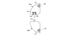
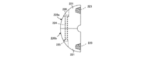
また、連結部材の他の実施形態として、図2又は図3に示す構造のものを用いることができる。図2及び図3は、連結部材の他の実施形態を示す平面模式図である。
図2に示す連結部材120a、120bは、各鉄筋10へ接続するための接続部121をそれぞれ独立して設け、鉄筋10の端部に接続部121を螺着した後に、接続部121同士を接続して一体とする。すなわち、図2に示す連結部材120a、120bは分割構造となっており、各鉄筋10の端部に接続部121を取り付けて、分割された接続部121を一体とすることにより定着構造を形成する。
Further, as another embodiment of the connecting member, one having the structure shown in FIG. 2 or 3 can be used. 2 and 3 are schematic plan views showing other embodiments of the connecting member.
The connecting
この連結部材120a、120bは、2分割構造となっており、それぞれ各鉄筋10へ接続するための接続部121を有している。また、一方の接続部121には他方の接続部121へ向かって突出した連結突起124が設けられており、他方の接続部121には連結突起124を係止するための機構が設けられている。連結突起124は、基端部から中央部へ向かって拡径すると共に、中央部から先端部へ向かって縮径している。連結突起124を係止するための機構は、凹部125と、凹部125内に設けた楔部材126と、楔部材126を凹部125の開口側に向かって押圧するバネ127とを備えている。楔部材126は、連結突起124を係止しない状態で、凹部125の開口側に向かって縮径した形状となっており、連結突起124の進入に伴い、バネ127の付勢力に抗して凹部125の奥へ向かって移動すると、先端部側の間隔が広がり連結突起124の先端部を受け入れる。そして、連結突起124の楔部材126の中央部が通過すると、楔部材126はバネ127の付勢力により凹部125の開口側へ押し戻されて連結突起124を受け入れ、凹部125内に連結突起124を係止することができる。
各接続部121には、鉄筋10のテーパーネジ部11を螺着するための雌ネジ部123が設けられている。
Each of the connecting
Each connecting
図3に示す連結部材220a、220bは、各鉄筋10へ接続するための接続部221をそれぞれ独立して設け、鉄筋10の端部に接続部221を螺着した後に、接続部221同士を接続して一体とする。すなわち、図3に示す連結部材220a、220bは分割構造となっており、各鉄筋10の端部に接続部221を取り付けて、分割された接続部221を一体とすることにより定着構造を形成する。
The
この連結部材220は、2分割構造となっており、それぞれ各鉄筋10へ接続するための接続部221を有している。また、各接続部221には、接続部221を一体とした際に一連となるボルト挿通孔224が設けられている。そして、各鉄筋10の端部に接続部221を取り付け、各接続部221に設けたボルト挿通孔224に一連にボルト225を挿通し、ボルト225の先端にナット226を螺着することにより、接続部221を一体として定着構造を形成する。
各接続部221には、鉄筋10のテーパーネジ部11を螺着するための雌ネジ部223が設けられている。
This connecting member 220 has a two-part structure, and has a connecting
Each
<鉄筋コンクリート構造物への鉄筋の定着方法>
本発明の実施形態に係る鉄筋コンクリート構造物への鉄筋の定着方法は、基本的な工程として、鉄筋コンクリート構造物に対して、鉄筋10及び連結部材20を挿入するための挿入孔を形成する工程と、鉄筋10及び連結部材20を挿入孔30、130a、130b(図4、図5参照)内に挿入する工程と、挿入孔30、130a、130b内への鉄筋10及び連結部材20の挿入前あるいは挿入後のいずれかの時点で、挿入孔30、130a、130b内に充填材を注入すると共に、鉄筋10の端部に連結部材20を接続する工程と、を含んでいる。
<Method of fixing reinforcing bars to reinforced concrete structures>
The fixing method of the reinforcing bar to the reinforced concrete structure according to the embodiment of the present invention includes, as a basic process, forming an insertion hole for inserting the reinforcing
<挿入孔>
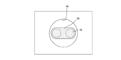
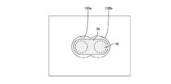
図4及び図5を参照して、鉄筋コンクリート構造物に形成する挿入孔について説明する。図4及び図5は、挿入孔の形状を示す断面模式図である。
図4に示す例は、定着構造全体を1つの挿入孔30内に挿入する1孔タイプのものである。すなわち、1孔タイプの挿入孔30は、鉄筋10及び連結部材20が一体となった定着構造の最大直径よりも大きな直径を有する1つの挿入孔30を形成し、この挿入孔30内に定着構造を挿入するようになっている。この1孔タイプの挿入孔30は、1回の穿孔工程で挿入孔30を形成することができるため、迅速な施工を行うことができる。
<Insertion hole>
With reference to FIG.4 and FIG.5, the insertion hole formed in a reinforced concrete structure is demonstrated. 4 and 5 are schematic cross-sectional views showing the shape of the insertion hole.
The example shown in FIG. 4 is a one-hole type in which the entire fixing structure is inserted into one
図5に示す例は、各鉄筋10の外径にそれぞれ対応して別個の挿入孔130a、130bを形成した2孔タイプのものである。すなわち、2孔タイプの挿入孔130a、130bは、各鉄筋10の最大直径よりも大きな直径を有する挿入孔130a、130bを鉄筋10毎に形成し、各挿入孔130a、130b内にそれぞれ鉄筋10を挿入するようになっている。この2孔タイプの挿入孔130a、130bは、1孔タイプのものと比較して、挿入孔の断面積を小さくすることができ、十分な被り厚を確保することが可能となる。また、挿入孔の断面積が小さいので、充填材の使用量を低減することが可能である。
挿入孔として、いずれのタイプのものを形成するかは、施工対象となる鉄筋コンクリート構造物の構成や状態等に応じて適宜選択することができる。
The example shown in FIG. 5 is a two-hole type in which separate
Which type of insertion hole is to be formed can be appropriately selected according to the configuration or state of the reinforced concrete structure to be constructed.
<他の実施形態>
本発明の鉄筋コンクリート構造物への鉄筋の定着構造及び定着方法は、上述した各実施形態に限定されるものではなく、適宜変更して実施することができる。例えば、一対(2本)の鉄筋10を用いるのではなく、3本以上の鉄筋10を一組として用いてもよい。この場合、連結部材20には鉄筋10の数に応じた接続部21が形成される。
また、鉄筋10の両端部に連結部材20を取り付けるのではなく、施工対象となる鉄筋コンクリート構造物の構成や状態等に応じて、いずれか一方の端部のみに連結部材20を取り付けてもよい。
さらに、上述した実施形態では、鉄筋10と連結部材20とをテーパーネジ構造により接続しているが、一般的なネジ構造を用いて接続してもよいし、摩擦圧接等の技術を用いて接続してもよい。
<Other embodiments>
The fixing structure and fixing method of reinforcing bars to the reinforced concrete structure of the present invention are not limited to the above-described embodiments, and can be implemented with appropriate modifications. For example, instead of using a pair (two) of reinforcing
Moreover, instead of attaching the connecting
Further, in the above-described embodiment, the reinforcing
<従来技術との比較>
以上説明したように、本発明の鉄筋コンクリート構造物への鉄筋の定着構造及び定着方法では、鉄筋コンクリート構造物に形成した挿入孔内に鉄筋を挿入し、この鉄筋の端部に連結部材を連結した構造であるため、半円形フックを適用できない箇所であっても鉄筋の定着を行うことが可能となる。
<Comparison with conventional technology>
As described above, in the fixing structure and fixing method of the reinforcing bar to the reinforced concrete structure according to the present invention, the reinforcing bar is inserted into the insertion hole formed in the reinforced concrete structure, and the connecting member is connected to the end of the reinforcing bar. Therefore, it is possible to fix the reinforcing bar even at a location where the semicircular hook cannot be applied.
10 鉄筋
11 テーパーネジ部
20 連結部材
21 接続部
22 本体部
23 雌ネジ部
30 挿入孔
120a、120b 連結部材
121 接続部
123 雌ネジ部
124 連結突起
125 凹部
126 楔部材
127 バネ
130a、130b 挿入孔
220a、220b 連結部材
221 接続部
223 雌ネジ部
224 ボルト挿通孔
225 ボルト
226 ナット
DESCRIPTION OF
Claims (4)
略平行に配置した一組の鉄筋と、各鉄筋の端部に取り付けて各鉄筋を一体に連結する連結部材とを備え、
前記連結部材は、連結する各鉄筋にそれぞれ相対する接続部と、各接続部の間に掛け渡す本体部とからなることを特徴とする鉄筋コンクリート構造物への鉄筋の定着構造。 A fixing structure for fixing a reinforcing bar to a reinforced concrete structure,
A set of reinforcing bars arranged substantially in parallel, and a connecting member that attaches to the end of each reinforcing bar and connects the reinforcing bars together;
The connecting member includes a connecting portion facing each reinforcing bar to be connected, and a main body portion spanned between the connecting portions, and the reinforcing bar fixing structure to the reinforced concrete structure.
前記連結部材の接続部は、前記鉄筋の端部に形成したテーパーネジ部に螺着する雌ネジ部を有することを特徴とする請求項1に記載の鉄筋コンクリート構造物への鉄筋の定着構造。 The rebar has a taper screw portion formed by cutting into a tapered shape after plastic hardening of the end portion,
The reinforcing member fixing structure to the reinforced concrete structure according to claim 1, wherein the connecting portion of the connecting member has a female screw portion screwed into a taper screw portion formed at an end portion of the reinforcing bar.
鉄筋コンクリート構造物に対して、鉄筋及び連結部材を挿入するための挿入孔を形成する工程と、
前記鉄筋及び前記連結部材を前記挿入孔内に挿入する工程と、
前記挿入孔内への鉄筋及び連結部の挿入前あるいは挿入後のいずれかの時点で、前記挿入孔内に充填材を注入すると共に、鉄筋の端部に連結部材を接続する工程と、を含み、
前記鉄筋は、略平行に配置された一組からなり、
前記連結部材は、各鉄筋の端部に取り付けて各鉄筋を一体に連結する連結部材を備え、
前記連結部材は、連結する各鉄筋にそれぞれ相対する接続部と、各接続部の間に掛け渡す本体部とからなることを特徴とする鉄筋コンクリート構造物への鉄筋の定着方法。 A fixing method for fixing a reinforcing bar to a reinforced concrete structure,
Forming an insertion hole for inserting a reinforcing bar and a connecting member with respect to a reinforced concrete structure;
Inserting the rebar and the connecting member into the insertion hole;
And a step of injecting a filler into the insertion hole at any time before or after insertion of the reinforcing bar and the connecting part into the insertion hole and connecting a connecting member to the end of the reinforcing bar. ,
The reinforcing bars consist of a set arranged substantially in parallel,
The connecting member includes a connecting member that is attached to an end of each reinforcing bar and integrally connects the reinforcing bars,
The connecting member includes a connecting portion facing each reinforcing bar to be connected, and a main body portion that spans between the connecting portions, and a method for fixing the reinforcing bar to the reinforced concrete structure.
Priority Applications (1)
| Application Number | Priority Date | Filing Date | Title |
|---|---|---|---|
| JP2008260212A JP5392749B2 (en) | 2008-10-07 | 2008-10-07 | Reinforcing structure of reinforcing bar to reinforced concrete structure |
Applications Claiming Priority (1)
| Application Number | Priority Date | Filing Date | Title |
|---|---|---|---|
| JP2008260212A JP5392749B2 (en) | 2008-10-07 | 2008-10-07 | Reinforcing structure of reinforcing bar to reinforced concrete structure |
Publications (2)
| Publication Number | Publication Date |
|---|---|
| JP2010090574A true JP2010090574A (en) | 2010-04-22 |
| JP5392749B2 JP5392749B2 (en) | 2014-01-22 |
Family
ID=42253550
Family Applications (1)
| Application Number | Title | Priority Date | Filing Date |
|---|---|---|---|
| JP2008260212A Active JP5392749B2 (en) | 2008-10-07 | 2008-10-07 | Reinforcing structure of reinforcing bar to reinforced concrete structure |
Country Status (1)
| Country | Link |
|---|---|
| JP (1) | JP5392749B2 (en) |
Citations (5)
| Publication number | Priority date | Publication date | Assignee | Title |
|---|---|---|---|---|
| JPS5869965A (en) * | 1981-10-20 | 1983-04-26 | 株式会社熊谷組 | Reinforcement of existing reinforced concrete pillar |
| JPH0657883A (en) * | 1992-01-24 | 1994-03-01 | Erico Internatl Corp | Bar splice for reinforcement and sleeve and manufacture of sleeve and bar connection structure |
| JP2001303773A (en) * | 2000-04-19 | 2001-10-31 | East Japan Railway Co | Reinforcing method for reinforced concrete column |
| JP2005029991A (en) * | 2003-07-08 | 2005-02-03 | Nippon Steel Composite Co Ltd | Reinforcing method of concrete structure |
| JP2006225878A (en) * | 2005-02-15 | 2006-08-31 | Shimizu Corp | Reinforcement structure of masonry construction structure |
-
2008
- 2008-10-07 JP JP2008260212A patent/JP5392749B2/en active Active
Patent Citations (5)
| Publication number | Priority date | Publication date | Assignee | Title |
|---|---|---|---|---|
| JPS5869965A (en) * | 1981-10-20 | 1983-04-26 | 株式会社熊谷組 | Reinforcement of existing reinforced concrete pillar |
| JPH0657883A (en) * | 1992-01-24 | 1994-03-01 | Erico Internatl Corp | Bar splice for reinforcement and sleeve and manufacture of sleeve and bar connection structure |
| JP2001303773A (en) * | 2000-04-19 | 2001-10-31 | East Japan Railway Co | Reinforcing method for reinforced concrete column |
| JP2005029991A (en) * | 2003-07-08 | 2005-02-03 | Nippon Steel Composite Co Ltd | Reinforcing method of concrete structure |
| JP2006225878A (en) * | 2005-02-15 | 2006-08-31 | Shimizu Corp | Reinforcement structure of masonry construction structure |
Also Published As
| Publication number | Publication date |
|---|---|
| JP5392749B2 (en) | 2014-01-22 |
Similar Documents
| Publication | Publication Date | Title |
|---|---|---|
| JP5953075B2 (en) | Wood | |
| JP4029105B2 (en) | Connector, PC member manufacturing apparatus and manufacturing method | |
| KR101285704B1 (en) | A reinforcing bar connector | |
| KR101097958B1 (en) | Anchor bolt for fixing wire | |
| KR200415050Y1 (en) | Coupling device of reinforcing rods | |
| JP5392749B2 (en) | Reinforcing structure of reinforcing bar to reinforced concrete structure | |
| KR100837113B1 (en) | Reinforcing bar coupler | |
| JP2015059314A (en) | Connection structure of screw-knotted reinforcing bar | |
| JP4687040B2 (en) | Connection device for concrete components | |
| JP5002428B2 (en) | Fastener | |
| KR101003981B1 (en) | Removable Ground Anchor Body | |
| CN114555958A (en) | Press-fit nut for assembly, press-fit nut-bolt assembly, and method of constructing steel-concrete composite structure using the same | |
| JP4056027B2 (en) | Segment joint structure | |
| JP4865104B2 (en) | Design method for composite structural beams | |
| JP4866894B2 (en) | Reinforcing bar with fixing part, material for reinforcing bar with fixing part, and anchor bolt | |
| JP2001003518A (en) | Joint for placing joint and jointing member therefor | |
| JP2007321420A (en) | Reinforcing bar holder | |
| JP2005232750A (en) | Reinforcing fitting for concrete structure | |
| JP6893949B2 (en) | Connection structure and connection method between members | |
| JP5327779B2 (en) | Reinforcing bar anchoring structure | |
| JP4178047B2 (en) | Rebar end fixing device | |
| KR200141871Y1 (en) | Connector of steel reinforcing | |
| JP7023473B1 (en) | Construction method of profile holder with reinforcement and rehabilitation pipe | |
| JP2009209673A (en) | Mounting structure of pile head joining structure and method of installing pile head joining structure | |
| JP6921413B2 (en) | Reinforcing bar joints and rebar assemblies, as well as precast reinforced concrete bodies |
Legal Events
| Date | Code | Title | Description |
|---|---|---|---|
| A621 | Written request for application examination |
Free format text: JAPANESE INTERMEDIATE CODE: A621 Effective date: 20110926 |
|
| A521 | Request for written amendment filed |
Free format text: JAPANESE INTERMEDIATE CODE: A821 Effective date: 20110926 |
|
| A977 | Report on retrieval |
Free format text: JAPANESE INTERMEDIATE CODE: A971007 Effective date: 20121206 |
|
| A131 | Notification of reasons for refusal |
Free format text: JAPANESE INTERMEDIATE CODE: A131 Effective date: 20121212 |
|
| A521 | Request for written amendment filed |
Free format text: JAPANESE INTERMEDIATE CODE: A523 Effective date: 20130205 |
|
| TRDD | Decision of grant or rejection written | ||
| A01 | Written decision to grant a patent or to grant a registration (utility model) |
Free format text: JAPANESE INTERMEDIATE CODE: A01 Effective date: 20131003 |
|
| A61 | First payment of annual fees (during grant procedure) |
Free format text: JAPANESE INTERMEDIATE CODE: A61 Effective date: 20131009 |
|
| R150 | Certificate of patent or registration of utility model |
Free format text: JAPANESE INTERMEDIATE CODE: R150 Ref document number: 5392749 Country of ref document: JP Free format text: JAPANESE INTERMEDIATE CODE: R150 |
|
| S531 | Written request for registration of change of domicile |
Free format text: JAPANESE INTERMEDIATE CODE: R313531 |
|
| R350 | Written notification of registration of transfer |
Free format text: JAPANESE INTERMEDIATE CODE: R350 |
|
| S111 | Request for change of ownership or part of ownership |
Free format text: JAPANESE INTERMEDIATE CODE: R313115 |
|
| R350 | Written notification of registration of transfer |
Free format text: JAPANESE INTERMEDIATE CODE: R350 |
|
| R250 | Receipt of annual fees |
Free format text: JAPANESE INTERMEDIATE CODE: R250 |
|
| R250 | Receipt of annual fees |
Free format text: JAPANESE INTERMEDIATE CODE: R250 |
|
| R250 | Receipt of annual fees |
Free format text: JAPANESE INTERMEDIATE CODE: R250 |
|
| R250 | Receipt of annual fees |
Free format text: JAPANESE INTERMEDIATE CODE: R250 |
|
| R250 | Receipt of annual fees |
Free format text: JAPANESE INTERMEDIATE CODE: R250 |
|
| R250 | Receipt of annual fees |
Free format text: JAPANESE INTERMEDIATE CODE: R250 |