JP2010089575A - Vehicle drive controller - Google Patents
Vehicle drive controller Download PDFInfo
- Publication number
- JP2010089575A JP2010089575A JP2008259641A JP2008259641A JP2010089575A JP 2010089575 A JP2010089575 A JP 2010089575A JP 2008259641 A JP2008259641 A JP 2008259641A JP 2008259641 A JP2008259641 A JP 2008259641A JP 2010089575 A JP2010089575 A JP 2010089575A
- Authority
- JP
- Japan
- Prior art keywords
- torque
- dog
- stroke
- release
- time
- Prior art date
- Legal status (The legal status is an assumption and is not a legal conclusion. Google has not performed a legal analysis and makes no representation as to the accuracy of the status listed.)
- Granted
Links
Images


Classifications
-
- Y—GENERAL TAGGING OF NEW TECHNOLOGICAL DEVELOPMENTS; GENERAL TAGGING OF CROSS-SECTIONAL TECHNOLOGIES SPANNING OVER SEVERAL SECTIONS OF THE IPC; TECHNICAL SUBJECTS COVERED BY FORMER USPC CROSS-REFERENCE ART COLLECTIONS [XRACs] AND DIGESTS
- Y02—TECHNOLOGIES OR APPLICATIONS FOR MITIGATION OR ADAPTATION AGAINST CLIMATE CHANGE
- Y02T—CLIMATE CHANGE MITIGATION TECHNOLOGIES RELATED TO TRANSPORTATION
- Y02T10/00—Road transport of goods or passengers
- Y02T10/60—Other road transportation technologies with climate change mitigation effect
- Y02T10/62—Hybrid vehicles
Landscapes
- Control Of Transmission Device (AREA)
- Hybrid Electric Vehicles (AREA)
- Mechanical Operated Clutches (AREA)
Abstract
Description
本発明は、ハイブリッド車両に好適な駆動制御装置に関する。 The present invention relates to a drive control device suitable for a hybrid vehicle.
エンジンに加えて、電動機やモータジェネレータなどの動力源を備えるハイブリッド車両が既知である。ハイブリッド車両では、エンジンを可及的に高効率状態で運転する一方、駆動力やエンジンブレーキ力の過不足を電動機又はモータジェネレータで補う。 Hybrid vehicles that include a power source such as an electric motor or a motor generator in addition to an engine are known. In a hybrid vehicle, an engine is operated in a highly efficient state as much as possible, while an excess or deficiency in driving force or engine braking force is compensated by an electric motor or a motor generator.
上記のようなハイブリッド車両において、無段変速モードと固定変速比モードとを切り替えて運転することが可能なように構成された変速機構の例が特許文献1に提案されている。具体的には、2つの遊星歯車機構を組み合わせて4つの回転要素を有する動力分配機構が構成され、4つの回転要素がそれぞれエンジン、第1のモータジェネレータ、出力軸及びブレーキに接続される。ブレーキを解放した状態では、第1のモータジェネレータの回転数を連続的に変化させることにより、エンジンの回転数が連続的に変化し、無段変速モードでの運転が実行される。一方、ブレーキを固定した状態では、上記の回転要素の1つの回転が阻止されることにより変速比が固定となり、固定変速比モードでの運転が実行される。また、無段変速モードと固定変速比モードとを切り替える変速機構は、従来の湿式多板クラッチではなく、係合要素の歯と被係合要素の歯とを噛合させる噛合機構を用いたものが知られている。 In the hybrid vehicle as described above, Patent Document 1 proposes an example of a speed change mechanism configured to be able to operate by switching between a continuously variable transmission mode and a fixed speed ratio mode. Specifically, a power distribution mechanism having four rotating elements is configured by combining two planetary gear mechanisms, and the four rotating elements are connected to the engine, the first motor generator, the output shaft, and the brake, respectively. In a state where the brake is released, the engine speed is continuously changed by continuously changing the rotation speed of the first motor generator, and the operation in the continuously variable transmission mode is executed. On the other hand, in a state where the brake is fixed, the gear ratio is fixed by preventing one rotation of the rotating element, and the operation in the fixed gear ratio mode is executed. In addition, the speed change mechanism for switching between the continuously variable transmission mode and the fixed speed ratio mode is not a conventional wet multi-plate clutch, but uses a meshing mechanism that meshes the teeth of the engaging element and the teeth of the engaged element. Are known.
しかしながら、上記した特許文献1に記載された技術では、ドグ歯が設けられたドグクラッチなどの噛合機構を用いた場合、固定変速比モードから無段変速モードへ変速する際に、噛合機構におけるドグ歯が受けている反力(以下、「ドグ部作用トルク」と呼ぶ。)を適切に推定することが困難であった。その理由の1つとしては、第1のモータジェネレータではなく噛合機構のドグ歯でエンジン反力を支持しているために、エンジントルクを精度良く推定できなかったことが挙げられる。このようにドグ部作用トルクを適切に推定できなかった場合には、変速時間(噛合機構の解放に要する時間若しくは係合に要する時間)にばらつきが生じてしまう可能性があった。 However, in the technique described in Patent Document 1 described above, when a meshing mechanism such as a dog clutch provided with dog teeth is used, the dog teeth in the meshing mechanism are used when shifting from the fixed gear ratio mode to the continuously variable transmission mode. It has been difficult to properly estimate the reaction force (hereinafter referred to as “dog portion acting torque”). One of the reasons is that the engine torque could not be accurately estimated because the engine reaction force is supported not by the first motor generator but by the dog teeth of the meshing mechanism. As described above, when the dog portion operating torque cannot be properly estimated, there is a possibility that the shift time (the time required for releasing the meshing mechanism or the time required for engaging) may vary.
本発明は、上記のような課題を解決するためになされたものであり、ドグ部作用トルクを適切に推定することで解放時間のばらつきを低減することが可能な車両の駆動制御装置を提供することを目的とする。 The present invention has been made to solve the above-described problems, and provides a vehicle drive control device capable of reducing variation in release time by appropriately estimating the dog portion operation torque. For the purpose.
本発明の1つの観点では、複数のドグ歯が設けられた係合要素及び被係合要素を有し、前記係合要素及び前記被係合要素の少なくともいずれかのドグ歯をストロークさせることで係合/解放を行う噛合機構を備える車両の駆動制御装置は、前記噛合機構の係合動作時及び解放動作時において、前記ドグ歯におけるストロークの変化量から前記解放に要する時間を求め、求められた前記解放に要する時間から前記ドグ歯に作用するトルクを推定するトルク推定手段を備える。 In one aspect of the present invention, an engagement element having a plurality of dog teeth and an engaged element are provided, and at least one of the engagement elements and the engaged element is stroked. A vehicle drive control device having a meshing mechanism that performs engagement / release calculates a time required for the release from an amount of stroke change in the dog teeth during the engagement operation and the release operation of the meshing mechanism. And torque estimation means for estimating a torque acting on the dog teeth from the time required for the release.
上記の車両の駆動制御装置は、複数のドグ歯が設けられた係合要素及び被係合要素の少なくともいずれかのドグ歯をストローク動作させることで係合/解放を行う噛合機構を備える。トルク推定手段は、噛合機構の係合動作時及び解放動作時において、ドグ歯におけるストロークの変化量から解放に要する時間を求め、求められた解放に要する時間からドグ歯に作用するトルクを推定する。これにより、ドグ歯に作用するトルクを精度良く推定することができる。したがって、このように推定されたトルクに基づいて噛合機構を解放する制御を行うことにより、解放時間のばらつきを低減することが可能となる。 The drive control apparatus for a vehicle includes a meshing mechanism that engages / releases by stroke-operating at least one of the engagement elements provided with a plurality of dog teeth and the engaged elements. The torque estimation means obtains the time required for the release from the stroke change amount in the dog teeth during the engagement operation and the release operation of the meshing mechanism, and estimates the torque acting on the dog teeth from the obtained time required for the release. . Thereby, the torque which acts on a dog tooth can be estimated accurately. Therefore, by performing control to release the meshing mechanism based on the torque estimated in this way, it is possible to reduce variation in release time.
上記の車両の駆動制御装置の一態様では、前記トルク推定手段は、前記ストローク方向に作用させる力を、前記トルクの推定を行う前よりも低減させてから、前記トルクの推定を行う。 In one aspect of the vehicle drive control apparatus, the torque estimation means estimates the torque after reducing the force applied in the stroke direction more than before estimating the torque.
この態様では、トルク推定手段は、ストローク方向に作用させる力を弱めることでストローク変化を緩やかにしてから、ドグ歯に作用するトルクを推定する。こうすることにより、トルクの推定精度を向上させることが可能となる。 In this aspect, the torque estimation means estimates the torque acting on the dog teeth after reducing the stroke change by weakening the force acting in the stroke direction. By doing so, it is possible to improve the estimation accuracy of the torque.
上記の車両の駆動制御装置の他の一態様では、前記係合要素及び前記被係合要素の少なくともいずれかにモータジェネレータが連結されており、前記モータジェネレータからトルクを付与させることで前記ドグ歯に作用するトルクを変化させた状態での前記ストロークの変化量から、前記トルク推定手段によって推定された前記ドグ歯に作用するトルクの正負を判定する第1のトルク符号判定方法を実行するトルク符号判定手段を更に備える。 In another aspect of the vehicle drive control device described above, a motor generator is connected to at least one of the engaging element and the engaged element, and the dog teeth are provided by applying torque from the motor generator. Torque code for executing a first torque code determination method for determining whether the torque acting on the dog teeth estimated by the torque estimating means is positive or negative based on the amount of change in the stroke when the torque acting on the torque is changed A determination unit is further provided.
この態様では、上記のように推定されたドグ歯に作用するトルクは絶対値で得られるため、トルク符号判定手段は、第1のトルク符号判定方法を実行することで、当該トルクの正負を判定する。具体的には、トルク符号判定手段は、モータジェネレータからトルクを付与させることでドグ歯に作用するトルクを変化させた際のストロークの変化量(勾配)から、ドグ歯に作用するトルクの正負を判定する。これにより、精度良く、ドグ歯に作用するトルクの正負を判定することができる。 In this aspect, since the torque acting on the dog teeth estimated as described above is obtained as an absolute value, the torque sign determination means determines whether the torque is positive or negative by executing the first torque sign determination method. To do. Specifically, the torque sign determination means determines whether the torque acting on the dog teeth is positive or negative from the stroke change amount (gradient) when the torque acting on the dog teeth is changed by applying torque from the motor generator. judge. Thereby, it is possible to accurately determine whether the torque acting on the dog teeth is positive or negative.
上記の車両の駆動制御装置において好適には、前記トルク符号判定手段は、前記トルク推定手段によって推定された前記ドグ歯に作用するトルクの大きさに応じて、前記第1のトルク符号判定方法と、前記ドグ歯におけるバックラッシ相当の位相変化量から前記ドグ歯に作用するトルクの正負を判定する第2のトルク符号判定方法とを切り替えて、前記トルク推定手段によって推定された前記ドグ歯に作用するトルクの正負を判定する。これにより、ドグ部作用トルクの符号判定における信頼性を向上させることができる。 Preferably, in the vehicle drive control device, the torque code determination means includes the first torque code determination method according to the magnitude of the torque acting on the dog teeth estimated by the torque estimation means. And switching to a second torque sign determination method for determining whether the torque acting on the dog teeth is positive or negative based on a phase change amount equivalent to backlash in the dog teeth, and acting on the dog teeth estimated by the torque estimating means. Determine whether the torque is positive or negative. Thereby, the reliability in the code | symbol determination of a dog part action torque can be improved.
上記の車両の駆動制御装置の他の一態様では、前記トルク推定手段が前記ストロークの変化量を検出できなかった場合に、前記解放時におけるショックが許容範囲内となるように、前記ストローク方向に作用させる力を低減させる手段を更に備える。 In another aspect of the drive control apparatus for a vehicle described above, in the stroke direction, the shock at the time of release is within an allowable range when the torque estimation unit cannot detect the change amount of the stroke. A means for reducing the applied force is further provided.
この態様によれば、所定以上のトルク誤差がある場合に解放してしまうことを適切に防止することができる。また、もし解放されても、解放時のショックの発生を抑制することができる。 According to this aspect, it is possible to appropriately prevent the release when there is a torque error of a predetermined value or more. Moreover, even if released, the occurrence of shock at the time of release can be suppressed.
上記の車両の駆動制御装置の他の一態様では、前記係合要素及び前記被係合要素の少なくともいずれかにモータジェネレータが連結されており、前記モータジェネレータからトルクを付与させて前記ドグ歯に所定トルクを作用させた状態で、前記ドグ歯をストロークさせることにより、前記ストローク時における摺動部分の摩擦係数を算出する摩擦係数算出手段を更に備える。 In another aspect of the vehicle drive control apparatus, a motor generator is connected to at least one of the engaging element and the engaged element, and torque is applied from the motor generator to the dog teeth. Friction coefficient calculation means is further provided for calculating the friction coefficient of the sliding portion during the stroke by stroking the dog teeth while applying a predetermined torque.
この態様によれば、摺動部分の摩擦係数における経時変化に対して適切に対応することが可能となる。具体的には、摺動部分の摩擦係数が変化した場合にも、解放時間のばらつきを適切に低減することができる。 According to this aspect, it is possible to appropriately cope with a change with time in the friction coefficient of the sliding portion. Specifically, even when the friction coefficient of the sliding portion changes, the release time variation can be appropriately reduced.
好適には、上記の車両の駆動制御装置は、内燃機関と、第1のモータジェネレータと、前記内燃機関及び前記第1のモータジェネレータが連結されると共に前記噛合機構が連結された動力分配機構と、駆動軸に接続された第2のモータジェネレータと、を具備し、前記噛合機構の解放/係合を行うことで無段変速モードと固定変速比モードとの間で変速モードの切り替えを行うハイブリッド車両に適用される。 Preferably, the vehicle drive control device includes an internal combustion engine, a first motor generator, a power distribution mechanism to which the internal combustion engine and the first motor generator are connected, and the meshing mechanism is connected. , A second motor generator connected to the drive shaft, and a shift mode switching between a continuously variable transmission mode and a fixed transmission ratio mode by releasing / engaging the meshing mechanism Applies to vehicles.
本発明における車両の駆動制御装置は、複数のドグ歯が設けられた係合要素及び被係合要素の少なくともいずれかのドグ歯をストローク動作させることで係合/解放を行う噛合機構を備える。トルク推定手段は、噛合機構の係合動作時及び解放動作時において、ドグ歯におけるストロークの変化量から解放に要する時間を求め、求められた解放に要する時間からドグ歯に作用するトルクを推定する。これにより、ドグ歯に作用するトルクを精度良く推定することができる。したがって、このように推定されたトルクに基づいて噛合機構を解放する制御を行うことにより、解放時間のばらつきを低減することが可能となる。 The vehicle drive control device according to the present invention includes a meshing mechanism that performs engagement / release by stroke-operating at least one of the engagement elements provided with a plurality of dog teeth and the engaged elements. The torque estimation means obtains the time required for the release from the stroke change amount in the dog teeth during the engagement operation and the release operation of the meshing mechanism, and estimates the torque acting on the dog teeth from the obtained time required for the release. . Thereby, the torque which acts on a dog tooth can be estimated accurately. Therefore, by performing control to release the meshing mechanism based on the torque estimated in this way, it is possible to reduce variation in release time.
以下、図面を参照して本発明の好適な実施の形態について説明する。 Preferred embodiments of the present invention will be described below with reference to the drawings.
[装置構成]
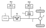
図1に本発明を適用したハイブリッド車両の概略構成を示す。図1の例は、機械分配式2モータ型と称されるハイブリッド車両であり、エンジン(内燃機関)1、第1のモータジェネレータMG1、第2のモータジェネレータMG2、動力分配機構20、を備える。動力源に相当するエンジン1と、回転数制御機構に相当する第1のモータジェネレータMG1とが動力分配機構20に連結されている。動力分配機構20の出力軸3には、駆動トルク又はブレーキ力のアシストを行うための副動力源である第2のモータジェネレータMG2が連結されている。第2のモータジェネレータMG2と出力軸3とはMG2変速部6を介して接続されている。さらに、出力軸3は最終減速機8を介して左右の駆動輪9に連結されている。第1のモータジェネレータMG1と第2のモータジェネレータMG2とは、バッテリ、インバータ、又は適宜のコントローラ(図2参照)を介して、もしくは直接的に電気的に接続され、第1のモータジェネレータMG1で生じた電力で第2のモータジェネレータMG2を駆動するように構成されている。
[Device configuration]
FIG. 1 shows a schematic configuration of a hybrid vehicle to which the present invention is applied. The example of FIG. 1 is a hybrid vehicle called a mechanical distribution type two-motor type, and includes an engine (internal combustion engine) 1, a first motor generator MG 1, a second motor generator MG 2, and a
エンジン1は燃料を燃焼して動力を発生する熱機関であり、ガソリンエンジン、ディーゼルエンジンなどが挙げられる。第1のモータジェネレータMG1はエンジン1からトルクを受けて回転することにより主として発電を行うものであり、発電に伴うトルクの反力が作用する。第1のモータジェネレータMG1の回転数を制御することにより、エンジン1の回転数が連続的に変化する。このような変速モードを無段変速モードという。無段変速モードは、後述する動力分配機構20の差動作用により実現される。
The engine 1 is a heat engine that generates power by burning fuel, and examples thereof include a gasoline engine and a diesel engine. The first motor generator MG1 generates power mainly by receiving torque from the engine 1 and rotating, and a reaction force of torque accompanying power generation acts. By controlling the rotational speed of first motor generator MG1, the rotational speed of engine 1 changes continuously. Such a speed change mode is called a continuously variable speed change mode. The continuously variable transmission mode is realized by a differential action of a
第2のモータジェネレータMG2は、駆動トルク又はブレーキ力を補助(アシスト)する装置である。駆動トルクをアシストする場合、第2のモータジェネレータMG2は電力の供給を受けて電動機として機能する。一方、ブレーキ力をアシストする場合には、第2のモータジェネレータMG2は、駆動輪9から伝達されるトルクにより回転させられて電力を発生する発電機として機能する。 The second motor generator MG2 is a device that assists the driving torque or the braking force. When assisting the drive torque, the second motor generator MG2 receives power supply and functions as an electric motor. On the other hand, when assisting the braking force, the second motor generator MG2 functions as a generator that is rotated by the torque transmitted from the drive wheels 9 to generate electric power.
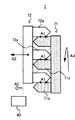
図2は、図1に示す第1のモータジェネレータMG1、第2のモータジェネレータMG2及び動力分配機構20などの構成を示す。
FIG. 2 shows the configuration of the first motor generator MG1, the second motor generator MG2 and the
動力分配機構20は、エンジン1の出力トルクを第1のモータジェネレータMG1と出力軸3とに分配する機構であり、差動作用を生じるように構成されている。具体的には複数組の差動機構を備え、互いに差動作用を生じる4つの回転要素のうち、第1の回転要素にエンジン1が連結され、第2の回転要素に第1のモータジェネレータMG1が連結され、第3の回転要素に出力軸3が連結される。第4の回転要素はドグブレーキ部7により固定可能となっている。
The
ドグブレーキ部7は、複数のドグ歯が設けられた係合要素(不図示)及び複数のドグ歯が設けられた被係合要素(不図示)を具備する噛合機構として構成されており、ブレーキ操作部5により制御される。詳しくは、ドグブレーキ部7において、被係合要素は回転可能に構成されており、係合要素は回転不能に構成されている。つまり、被係合要素は回転要素に相当し、係合要素は固定要素に相当する。また、係合要素は、軸方向にストローク可能に構成されている。なお、以下では、ドグブレーキ部7のことを、単に「ドグ部」とも表記する。
The dog brake unit 7 is configured as a meshing mechanism including an engagement element (not shown) provided with a plurality of dog teeth and an engaged element (not shown) provided with a plurality of dog teeth. Controlled by the
ドグブレーキ部7が第4の回転要素を固定していない状態では、第1のモータジェネレータMG1の回転数を連続的に変化させることによりエンジン1の回転数が連続的に変化し、無段変速モードが実現される。一方、ドグブレーキ部7が第4の回転要素を固定している状態では、動力分配機構20により決定される変速比がオーバードライブ状態(即ち、エンジン回転数が出力回転数より小さくなる状態)に固定され、固定変速比モードが実現される。
In a state where the dog brake unit 7 does not fix the fourth rotation element, the rotation speed of the engine 1 is continuously changed by continuously changing the rotation speed of the first motor generator MG1, and the continuously variable transmission mode Is realized. On the other hand, when the dog brake unit 7 is fixing the fourth rotating element, the transmission gear ratio determined by the
本実施形態では、図2に示すように、動力分配機構20は、2つの遊星歯車機構を組み合わせて構成される。第1の遊星歯車機構はリングギア21、キャリア22、サンギア23を備える。第2の遊星歯車機構はダブルピニオン式であり、リングギア25、キャリア26、サンギア27を備える。
In the present embodiment, as shown in FIG. 2, the
エンジン1の出力軸2は第1の遊星歯車機構のキャリア22に連結され、そのキャリア22は第2の遊星歯車機構のリングギア25に連結されている。これらが第1の回転要素を構成する。第1のモータジェネレータMG1のロータ11は第1の遊星歯車機構のサンギア23に連結され、これらが第2の回転要素を構成している。
The
第1の遊星歯車機構のリングギア21と第2の遊星歯車機構のキャリア26は相互に連結されているとともに出力軸3に連結されている。これらが第3の回転要素を構成している。また、第2の遊星歯車機構のサンギア27は回転軸29に連結されており、回転軸29とともに第4の回転要素を構成している。回転軸29はドグブレーキ部7により固定可能となっている。
The
電源ユニット30は、インバータ31、コンバータ32、HVバッテリ33及びコンバータ34を備える。第1のモータジェネレータMG1は電源線37によりインバータ31に接続されており、第2のモータジェネレータMG2は電源線38によりインバータ31に接続されている。また、インバータ31はコンバータ32に接続され、コンバータ32はHVバッテリ33に接続されている。さらに、HVバッテリ33はコンバータ34を介して補機バッテリ35に接続されている。
The
インバータ31は、モータジェネレータMG1及びMG2との間で電力の授受を行う。モータジェネレータの回生時には、インバータ31はモータジェネレータMG1及びMG2が回生により発電した電力を直流に変換し、コンバータ32へ供給する。コンバータ32は、インバータ31から供給される電力を電圧変換し、HVバッテリ33を充電する。一方、モータジェネレータの力行時には、HVバッテリ33から出力される直流電力はコンバータ32により昇圧され、電源線37又は38を介してモータジェネレータMG1又はMG2へ供給される。
HVバッテリ33の電力はコンバータ34により電圧変換されて補機バッテリ35に供給され、各種の補機の駆動に使用される。
The electric power of the
インバータ31、コンバータ32、HVバッテリ33及びコンバータ34の動作はECU4により制御されている。ECU4は制御信号S4を送信することにより、電源ユニット30内の各要素の動作を制御する。また、電源ユニット30内の各要素の状態などを示す必要な信号は制御信号S4としてECU4に供給される。具体的には、HVバッテリ33の状態を示すSOC(State Of Charge)及びバッテリの入出力制限値などは制御信号S4としてECU4に供給される。
The operation of the
また、ドグブレーキ部7には、係合要素のストローク量を検出するストローク量センサ40、及び係合要素と被係合要素との位相変化を検出可能な回転センサ41が設けられている。ストローク量センサ41は、検出したストローク量に対応する検出信号S40をECU4に供給し、回転センサ41は、検出した位相変化に対応する検出信号S41をECU4に供給する。なお、回転センサ41は、ドグブレーキ部7付近に設ける必要はない。
Further, the dog brake unit 7 is provided with a
ECU4は、エンジン1、第1のモータジェネレータMG1及び第2のモータジェネレータMG2との間で制御信号S1〜S3を送受信することにより、それらを制御する。また、ECU4はブレーキ操作部5に対してブレーキ操作指示信号S5を供給する。ブレーキ操作部5は、ブレーキ操作指示信号S5に従って、ドグブレーキ部7を係合(固定)/解放する制御を行う。具体的には、ブレーキ操作部5は、ドグブレーキ部7の係合要素をストロークさせる制御などを行う。なお、詳細は後述するが、ECU4は、本発明におけるトルク推定手段、トルク符号判定手段、及び摩擦係数算出手段に相当する。
The
図3に、動力分配機構20の固定変速比モードにおける共線図を示す。固定変速比モードでは、図3中の黒丸で示すように、係合要素のドグ歯と被係合要素のドグ歯とが噛み合うことによってドグブレーキ部7が固定される。以下では、係合要素のドグ歯を「係合側ドグ歯」と呼び、被係合要素のドグ歯を「被係合側ドグ歯」と呼ぶ。
FIG. 3 shows an alignment chart in the fixed speed ratio mode of the
無段変速モードでは、矢印90で示すように、エンジントルクの反力が第1のモータジェネレータMG1によって支持される。なお、図3は固定変速比モードにおける共線図を示しているが、説明の便宜上、この図を用いて無段変速モードの説明を行っている。これに対して、固定変速比モードでは、矢印91で示すように、エンジントルクの反力がドグブレーキ部7において機械的に支持される。
In the continuously variable transmission mode, as indicated by an
図4は、ドグブレーキ部7の構成を模式的に表している。図示のように、ドグブレーキ部7は、複数の被係合側ドグ歯71aが設けられた被係合要素71と、複数の係合側ドグ歯72aが設けられた係合要素72とを備えて構成される。なお、図4は、被係合要素71と係合要素72とが係合状態にある場合の図を示している。また、説明の便宜上、被係合要素71をハッチングして表している。
FIG. 4 schematically shows the configuration of the dog brake unit 7. As illustrated, the dog brake portion 7 includes an engaged element 71 provided with a plurality of engaged
被係合要素71は、図2に示した第2の遊星歯車機構のサンギア27に連結されており、矢印A3で示すように、第4の回転要素であるサンギア27の回転に従って回転する。具体的には、被係合要素71には、ドグ部作用トルクが付与されることで回転する。このドグ部作用トルクは、主動力(エンジントルクなど)や車両走行抵抗などのトルクと、第1のモータジェネレータMG1などのトルクとの合成トルク(詳しくは、ギア比換算したトルク)に相当する。主動力や車両走行抵抗などのトルクは、正確に把握することが困難であるという意味において未知量のトルクに相当する。また、第1のモータジェネレータMG1からのトルク(以下では、単に「MGトルク」とも呼ぶ。)は、正確に把握することができるという意味において既知量のトルクに相当する。
The engaged element 71 is connected to the
更に、ドグ部作用トルクは、直接的に若しくは間接的に、係合要素72におけるストロークに対する抵抗力となる。具体的には、ドグ部作用トルクは、係合時において、被係合側ドグ歯71aと係合側ドグ歯72aとの間などのストローク時の摺動部分における摩擦力(符号A1で示す)に影響を及ぼす。
Further, the dog portion acting torque becomes a resistance force against the stroke of the engaging
係合要素72は、回転不能に構成されていると共に、矢印A2で示す方向(軸方向)にストローク可能に構成されている。具体的には、係合要素72は、矢印A2で示す方向に力(以下、この力を「ストローク力」と呼ぶ。)が付与されることでストロークされる。例えば、ストローク力としては、バネ力や、電磁力や、流体圧力などが用いられる。
The engaging
ここで、符号A1で示すような被係合側ドグ歯71aと係合側ドグ歯72aとの間に働く摩擦力は、係合要素72におけるストローク方向への動作時にストロークを阻害する方向へ作用する。この場合、符号A1で示す摩擦力が、係合要素72に対して付与されるストローク力よりも小さくなった場合に、係合要素72が矢印A2の方向にストロークすることとなる。これにより、被係合要素71と係合要素72との係合が解放する。つまり、固定変速比モードから無段変速モードへ変速されることとなる。なお、ストローク量センサ40は、白抜き矢印A5で示すように係合要素72がストロークした際のストローク量を検出する。
Here, the frictional force acting between the engaged
なお、上記した係合要素72に対して付与するストローク力は、固定しても良いし、変化させても良い。つまり、一定のストローク力を付与する構成部を用いても良いし、ストローク力が変化可能に構成された構成部を用いても良い。以下で説明する制御において、ストローク力を制御する場合には、ストローク力が変化可能に構成された構成部を用いる必要がある。このようにストローク力を変化させる場合には、ECU4が当該ストローク力を制御することができる。
Note that the stroke force applied to the
[制御方法]
次に、本実施形態に係る制御方法について説明する。本実施形態では、ドグブレーキ部7を解放する場合において、言い換えると固定変速比モードから無段変速モードへ変速させる場合において、ドグブレーキ部7が係合状態から解放状態となるまでに要する時間(以下では、「解放時間」若しくは「解放ストローク時間」と呼ぶ。)のばらつきを低減するため、及び解放時のショック(変速ショック)を低減するための制御を行う。具体的には、本実施形態では、前述したドグ部作用トルクを精度良く推定する処理などを行うことによって、解放時間のばらつきの低減などを図る。
[Control method]
Next, a control method according to the present embodiment will be described. In the present embodiment, when the dog brake unit 7 is released, in other words, when shifting from the fixed gear ratio mode to the continuously variable transmission mode, the time required for the dog brake unit 7 to change from the engaged state to the released state (hereinafter, referred to as the following) , Referred to as “release time” or “release stroke time”), and control for reducing shock (shift shock) at the time of release is performed. Specifically, in the present embodiment, the variation in release time is reduced by performing the above-described process of accurately estimating the dog portion operating torque.
こうする理由は以下の通りである。固定変速比モードから無段変速モードへ変速する際に行われるドグブレーキ部7の解放は、ドグ部作用トルクの絶対値が小さい場合(例えば0である場合)には解放時間が短くなる傾向にあり、ドグ部作用トルクの絶対値が大きい場合には解放時間が長くなる傾向にある。また、固定変速比モードでは、第1のモータジェネレータMG1ではなくドグブレーキ部7でエンジン反力を受けているため、第1のモータジェネレータMG1からのMGトルクに基づいてエンジントルクの推定を行う無段変速モードと比較して、エンジントルクの推定精度が低下する傾向にある。更に、解放時間の短縮を狙い、係合要素72に付与するストローク力を強くすると変速ショックが増加する傾向にあり、また、変速ショックの低減を狙い、ストローク力を弱くすると解放時間が増加する傾向にある。このようなことから、解放時間の短縮と変速ショックの低減とを両立させることは困難であると言える。
The reason for this is as follows. The release of the dog brake unit 7 performed when shifting from the fixed gear ratio mode to the continuously variable transmission mode tends to shorten the release time when the absolute value of the dog unit operating torque is small (for example, 0). When the absolute value of the dog portion operating torque is large, the release time tends to be long. In the fixed gear ratio mode, since the engine reaction force is received not by the first motor generator MG1 but by the dog brake unit 7, the engine torque is estimated based on the MG torque from the first motor generator MG1. Compared with the shift mode, the estimation accuracy of the engine torque tends to decrease. Furthermore, when the stroke force applied to the
したがって、本実施形態では、ドグブレーキ部7を解放する場合において、解放時間のばらつきの低減及び変速ショックの低減を実現するために、ドグ部作用トルクを精度良く推定する処理などを行う。 Therefore, in the present embodiment, when the dog brake unit 7 is released, a process for accurately estimating the dog unit operating torque is performed in order to reduce the variation in release time and reduce the shift shock.
以下では、図5乃至図13を参照して、本実施形態においてECU4が行う制御方法について具体的に説明する。 Below, with reference to FIG. 5 thru | or FIG. 13, the control method which ECU4 performs in this embodiment is demonstrated concretely.
(ドグ部作用トルクの推定方法)
本実施形態では、ECU4は、上記したように、解放時間のばらつきの低減を実現するべく、ドグ部作用トルクの推定を行う。具体的には、ECU4は、ドグブレーキ部7の解放動作時などにおいて、係合要素72のストロークの変化量から解放ストローク時間を求め、求められた解放ストローク時間に基づいてドグ部作用トルクの推定を行う。そして、ECU4は、推定されたドグ部作用トルクなどに基づいて、ドグブレーキ部7を係合状態から解放させる制御を行う。
(Dog part acting torque estimation method)
In the present embodiment, as described above, the
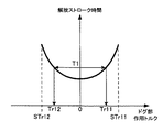
図5は、ドグ部作用トルクの推定方法を具体的に説明するための図である。図5は、ドグ部作用トルク(横軸)と解放ストローク時間(縦軸)との関係の一例を示している。これより、ドグ部作用トルクの絶対値が大きいほど解放ストローク時間が長くなる傾向にあり、ドグ部作用トルクの絶対値が小さいほど解放ストローク時間が短くなる傾向にあることがわかる。これは、ドグ部作用トルクの絶対値が大きいほど、係合要素72のストローク動作を阻害する摩擦力が大きくなり、ドグ部作用トルクの絶対値が小さいほど、係合要素72のストローク動作を阻害する摩擦力が小さくなるからである。
FIG. 5 is a diagram for specifically explaining a method of estimating the dog portion operation torque. FIG. 5 shows an example of the relationship between the dog portion acting torque (horizontal axis) and the release stroke time (vertical axis). From this, it can be seen that the release stroke time tends to be longer as the absolute value of the dog portion acting torque is larger, and the release stroke time tends to be shorter as the absolute value of the dog portion acting torque is smaller. This is because the frictional force that inhibits the stroke operation of the
なお、図5において破線で示すトルクSTr11、STr12(トルクSTr11、STr12は絶対値において等しい)は、摩擦力とストローク力とが概ね釣り合うようなトルクであり、トルクSTr11よりも大きなトルク若しくはトルクSTr12よりも小さなトルクがドグブレーキ部7に作用している場合には解放不能となる。以下では、このようなトルクSTr11、STr12を「スティックトルク」と呼ぶ。なお、スティックトルクは、ストローク力に応じて変化する。 Note that the torques STr11 and STr12 (the torques STr11 and STr12 are equal in absolute value) indicated by broken lines in FIG. 5 are torques in which the frictional force and the stroke force are approximately balanced, and are larger than the torque STr11 or the torque STr12. However, when a small torque is applied to the dog brake portion 7, it cannot be released. Hereinafter, such torques STr11 and STr12 are referred to as “stick torque”. The stick torque changes according to the stroke force.
本実施形態においては、ECU4は、図5に示すような関係を利用して、ドグ部作用トルクを求める。具体的には、まず、ECU4は、ストローク量センサ40を利用して係合要素72のストローク変化量を検出して、当該ストローク変化量から解放ストローク時間を求める。係合状態から完全に解放させるまでに必要なストローク量は分かっているので、このストローク量に基づいて、検出されたストローク変化量から解放ストローク時間を求めることができる。
In this embodiment, ECU4 calculates | requires a dog part action torque using a relationship as shown in FIG. Specifically, first, the
そして、ECU4は、図5に示すような関係に基づいて、求められた解放ストローク時間に対応するドグ部作用トルクを得る。例えば、解放ストローク時間として「T1」が得られた場合には、ドグ部作用トルクとして「Tr11」及び「Tr12」が得られる。「Tr11」は正のトルクであり、「Tr12」は負のトルクであり、「Tr11」と「Tr12」とは絶対値が等しい。
Then, the
以上のようにしてドグ部作用トルクを推定することで、当該推定されたドグ部作用トルクを用いてドグブレーキ部7の解放を行うことにより、ドグブレーキ部7の解放の信頼性を向上させることができると共に、解放時間(変速時間)のばらつきを低減することができる。 By estimating the dog portion operation torque as described above, by releasing the dog brake portion 7 using the estimated dog portion operation torque, the reliability of the release of the dog brake portion 7 can be improved. At the same time, the variation in release time (shift time) can be reduced.
なお、図5に示すようなドグ部作用トルクと解放ストローク時間との関係は、予め求めておいてマップとして記憶しておいても良いし、演算によって求めても良い。例えば、ストローク力としてバネ力を用いた場合には、バネ定数などから図5に示すような関係を容易に求めることができる。なお、図5では、ドグ部作用トルクの絶対値が同じときに解放ストローク時間が同じになる特性を示しているが、このような特性が得られるとは限らない。ドグ歯の形状によっては、ドグ部作用トルクの絶対値が同じでも、符号の正負で解放ストローク時間に差がでる特性になる場合がある。 The relationship between the dog portion acting torque and the release stroke time as shown in FIG. 5 may be obtained in advance and stored as a map, or may be obtained by calculation. For example, when a spring force is used as the stroke force, the relationship as shown in FIG. 5 can be easily obtained from the spring constant or the like. FIG. 5 shows a characteristic that the release stroke time is the same when the absolute value of the dog portion acting torque is the same, but such a characteristic is not always obtained. Depending on the shape of the dog tooth, even if the absolute value of the dog portion acting torque is the same, there may be a characteristic that the release stroke time varies depending on the sign.
次に、図6を参照して、ドグ部作用トルクの推定の精度を向上させるために行う制御について説明する。本実施形態においては、ECU4は、ドグ部作用トルクの推定精度の向上を図り、係合要素72に付与するストローク力を低減させてから、上記したような方法にてドグ部作用トルクの推定を行う。
Next, with reference to FIG. 6, the control performed in order to improve the precision of estimation of dog part action torque is demonstrated. In the present embodiment, the
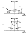
図6は、ストローク力を低減するとトルク推定精度が向上する理由を説明するための図である。図6(a)及び図6(b)は、それぞれ、ドグ部作用トルク(横軸)と解放ストローク時間(縦軸)との関係の一例を示している。具体的には、図6(a)はストローク力が比較的大きい場合のグラフB1を示しており、図6(b)はストローク力が比較的小さい場合のグラフB2を示している。図6(a)に示すように、ストローク力が大きい場合には、ドグ部作用トルクに対する解放ストローク時間の勾配が比較的小さいことがわかる。これに対して、図6(b)に示すように、ストローク力が小さい場合には、ドグ部作用トルクに対する解放ストローク時間の勾配が比較的大きいことがわかる。 FIG. 6 is a diagram for explaining the reason why the torque estimation accuracy is improved when the stroke force is reduced. FIGS. 6A and 6B show an example of the relationship between the dog portion operating torque (horizontal axis) and the release stroke time (vertical axis), respectively. Specifically, FIG. 6A shows a graph B1 when the stroke force is relatively large, and FIG. 6B shows a graph B2 when the stroke force is relatively small. As shown in FIG. 6A, it can be seen that when the stroke force is large, the gradient of the release stroke time with respect to the dog portion acting torque is relatively small. In contrast, as shown in FIG. 6B, it can be seen that when the stroke force is small, the gradient of the release stroke time with respect to the dog portion acting torque is relatively large.
より具体的には、ストローク力が大きい場合には、解放ストローク時間の差分ΔT21に対するドグ部作用トルクにおける差分はΔTr21、ΔTr22であるのに対して、ストローク力が小さい場合には、同じ解放ストローク時間の差分ΔT21に対するドグ部作用トルクにおける差分は、ΔTr21、ΔTr22よりも小さなΔTr23、ΔTr24であることがわかる。したがって、ストローク力が小さいほうが、解放ストローク時間からドグ部作用トルクを精度良く推定することができると言える。こうなるのは、ストローク力が小さい場合には、係合要素72のストローク変化が緩やかになるからである。
More specifically, when the stroke force is large, the difference in the dog portion acting torque with respect to the difference ΔT21 in the release stroke time is ΔTr21 and ΔTr22, whereas when the stroke force is small, the same release stroke time. It can be seen that the difference in the dog portion acting torque with respect to the difference ΔT21 is ΔTr23 and ΔTr24 smaller than ΔTr21 and ΔTr22. Therefore, it can be said that when the stroke force is small, the dog portion acting torque can be accurately estimated from the release stroke time. This is because when the stroke force is small, the stroke change of the
以上のような特性より、本実施形態では、ECU4は、ストローク力をトルクの推定前よりも低減させてから、前述したようなドグ部作用トルクの推定を実行する。例えば、ECU4は、予め定めたストローク力まで低減させて、当該ストローク力でのドグ部作用トルクと解放ストローク時間との関係(例えば、予めマップとして記憶されている)に基づいてドグ部作用トルクの推定を実行する。こうすることにより、ドグ部作用トルクの推定精度を向上させることが可能となる。
From the characteristics as described above, in the present embodiment, the
(ドグ部作用トルクの符号判定方法)
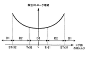
次に、上記した方法にて推定されたドグ部作用トルクの符号(正負)を判定する方法について説明する。上記した方法で推定されたドグ部作用トルクは絶対値で得られるため(図5など参照)、本実施形態では、ECU4は、当該ドグ部作用トルクの符号を判定するための処理を行う。具体的には、ECU4は、推定されたドグ部作用トルクの大きさに応じてドグ部作用トルクの符号を判定する2つの方法を切り替えて、ドグ部作用トルクの符号の判定を行う。以下では、この2つの方法の一方を「第1のトルク符号判定方法」と呼び、他方を「第2のトルク符号判定方法」と呼ぶ。
(Dog part acting torque sign determination method)
Next, a method for determining the sign (positive / negative) of the dog portion operating torque estimated by the above method will be described. Since the dog portion acting torque estimated by the above-described method is obtained as an absolute value (see FIG. 5 and the like), in this embodiment, the
第1のトルク符号判定方法は、MGトルクを付与させることでドグ部作用トルクを変化させた際のストロークの変化量(勾配)から、ドグ部作用トルクの符号を判定する方法である。ドグ部作用トルクは基本的にはエンジントルクとMGトルクとの合成トルクであるため、MGトルクを増減させると、これに伴ってドグ部作用トルクも増減することとなる。ドグ部作用トルクが増減した場合には、ドグ部作用トルクの正負に応じて解放ストローク時間が増減することとなる(つまり、ストロークの変化量(勾配)が変わる)ため、これに基づいてドグ部作用トルクの符号を判定することができる。 The first torque sign determination method is a method for determining the sign of the dog portion acting torque from the stroke change amount (gradient) when the dog portion acting torque is changed by applying the MG torque. Since the dog portion operating torque is basically a combined torque of the engine torque and the MG torque, when the MG torque is increased or decreased, the dog portion operating torque is also increased or decreased accordingly. When the dog portion acting torque increases or decreases, the release stroke time increases or decreases according to the positive or negative of the dog portion acting torque (that is, the stroke change amount (gradient) changes). The sign of the working torque can be determined.
第2のトルク符号判定方法は、係合要素72におけるバックラッシ相当の位相変化量から、ドグ部作用トルクの符号を判定する方法である。ドグ部作用トルクの符号に応じてドグ歯における位相の正負に偏りが生じるため、この位相の正負の偏りを回転センサ41で検出することにより、ドグ部作用トルクの符号を判定することができる。
The second torque sign determination method is a method for determining the sign of the dog portion operating torque from the phase change amount corresponding to the backlash in the
図7は、第1のトルク符号判定方法を具体的に説明するための図である。図7は、横軸にドグ部作用トルクを示しており、縦軸に解放ストローク時間を示している。ここでは、MGトルクを変化させることでドグ部作用トルクを増加させた場合を、例に挙げて説明する。図示のように、ドグ部作用トルクが正である場合には、矢印C1で示すようにドグ部作用トルクを増加させた場合、矢印C2で示すように解放ストローク時間が増加することがわかる。これに対して、ドグ部作用トルクが負である場合には、矢印C3で示すようにドグ部作用トルクを増加させた場合、矢印C4で示すように解放ストローク時間が減少することがわかる。 FIG. 7 is a diagram for specifically explaining the first torque code determination method. In FIG. 7, the abscissa indicates the dog portion acting torque, and the ordinate indicates the release stroke time. Here, a case where the dog portion operating torque is increased by changing the MG torque will be described as an example. As shown in the figure, when the dog portion acting torque is positive, when the dog portion acting torque is increased as shown by the arrow C1, the release stroke time is increased as shown by the arrow C2. On the other hand, when the dog portion acting torque is negative, it is understood that when the dog portion acting torque is increased as indicated by the arrow C3, the release stroke time is reduced as indicated by the arrow C4.
このように、ドグ部作用トルクが正であるか負であるかに応じて、ドグ部作用トルクを変化させたときの解放ストローク時間の変化が異なることがわかる。よって、解放ストローク時間の増減に応じて、ドグ部作用トルクが正であるか負であるかを判別することができる。具体的には、解放ストローク時間が増加した場合にはドグ部作用トルクが正であると判別することができ、解放ストローク時間が減少した場合にはドグ部作用トルクが負であると判別することができる。 Thus, it can be seen that the change in the release stroke time when the dog portion acting torque is changed differs depending on whether the dog portion acting torque is positive or negative. Therefore, it is possible to determine whether the dog portion operating torque is positive or negative according to the increase / decrease of the release stroke time. Specifically, when the release stroke time increases, it can be determined that the dog portion operating torque is positive, and when the release stroke time decreases, it is determined that the dog portion operating torque is negative. Can do.
したがって、本実施形態では、ECU4は、MGトルクを付与させることでドグ部作用トルクを変化させた際のストロークの変化量から、ドグ部作用トルクの符号を判定する第1のトルク符号判定方法を用いる。この場合、解放ストローク時間の減少は単位時間当たりのストローク変化量の増加で検出することができ、解放ストローク時間の増加は単位時間当たりのストローク変化量の減少で検出することができる。
Therefore, in the present embodiment, the
なお、第1のトルク符号判定方法は、第2のトルク符号判定方法よりも判定精度が高くなる傾向にある。また、図7では、MGトルクを変化させてドグ部作用トルクを増加させることで符号を判定する方法を示したが、この代わりに、MGトルクを変化させてドグ部作用トルクを減少させることで符号を判定することも可能である。 The first torque code determination method tends to have higher determination accuracy than the second torque code determination method. FIG. 7 shows a method of determining the sign by changing the MG torque and increasing the dog portion acting torque. Instead, by changing the MG torque and reducing the dog portion acting torque. It is also possible to determine the sign.
図8は、ドグ部作用トルクの大きさに応じて、第1のトルク符号判定方法と第2のトルク符号判定方法とを切り替える方法を説明するための図である。図8は、横軸にドグ部作用トルクを示しており、縦軸に解放ストローク時間を示している。 FIG. 8 is a diagram for explaining a method of switching between the first torque code determination method and the second torque code determination method according to the magnitude of the dog portion application torque. In FIG. 8, the abscissa indicates the dog portion acting torque, and the ordinate indicates the release stroke time.
本実施形態では、ドグ部作用トルクの絶対値がスティックトルクSTr31、STr32の絶対値(以下、単に「スティックトルクSTr3」と表記する。)よりも大きな領域D1では、第2のトルク符号判定方法を実行する。こうしているのは、領域D1では、ドグ部作用トルクの絶対値がスティックトルクSTr3よりも大きく、係合要素72がストロークしないため、ストローク変化を検出できないからである。よって、領域D1では、ストローク検出が不要である第2のトルク符号判定方法を実行する。
In the present embodiment, in the region D1 where the absolute value of the dog portion acting torque is larger than the absolute values of the stick torques STr31 and STr32 (hereinafter simply referred to as “stick torque STr3”), the second torque sign determination method is used. Execute. This is because in the region D1, the absolute value of the dog portion acting torque is larger than the stick torque STr3, and the
一方、ドグ部作用トルクの絶対値がスティックトルクSTr3以下であり、且つドグ部作用トルクの絶対値が所定トルクTr31、Tr32の絶対値(例えば、0付近の比較的小さな値であり、以下では単に「所定トルクTr3」と表記する。)以上である領域D2では、第1のトルク符号判定方法を実行する。こうしているのは、領域D2では、ドグ部作用トルクによる解放ストローク時間の勾配が大きいからである。また、ドグ部作用トルクを比較的大きめに変化させることができるからである。よって、領域D2では、判定精度が高い第1のトルク符号判定方法を実行する。 On the other hand, the absolute value of the dog portion working torque is less than or equal to the stick torque STr3, and the absolute value of the dog portion acting torque is the absolute value of the predetermined torques Tr31 and Tr32 (for example, a relatively small value near 0. (Indicated as “predetermined torque Tr3”.) In the region D2 as described above, the first torque code determination method is executed. This is because, in the region D2, the gradient of the release stroke time due to the dog portion acting torque is large. Moreover, it is because a dog part action torque can be changed comparatively large. Therefore, in the region D2, the first torque code determination method with high determination accuracy is executed.
一方、ドグ部作用トルクの絶対値が所定トルクTr3未満である領域D3では、第2のトルク符号判定方法を実行する。こうしているのは、領域D3では、ドグ部作用トルクが既に小さくなっており、ドグ部作用トルクを大きく変化させるべきではないからである。よって、領域D3では、ドグ部作用トルクを変化させないで判定を行うことが可能な第2のトルク符号判定方法を実行する。 On the other hand, in the region D3 where the absolute value of the dog portion acting torque is less than the predetermined torque Tr3, the second torque sign determination method is executed. This is because in the region D3, the dog portion operating torque is already small, and the dog portion operating torque should not be changed greatly. Therefore, in the region D3, the second torque code determination method capable of performing determination without changing the dog portion acting torque is executed.
なお、領域D2と領域D3との境界を規定する所定トルクTr3は、ドグ部作用トルクを比較的大きく変化させることが可能か否か(言い換えると、ドグ部作用トルクを大きく変化させても問題ないか否か)などを考慮に入れて設定される。また、所定トルクTr3は、ストローク力に応じたドグ部作用トルクと解放ストローク時間との関係ごとに設定される。 Note that the predetermined torque Tr3 that defines the boundary between the region D2 and the region D3 can determine whether or not the dog portion operating torque can be changed relatively large (in other words, there is no problem even if the dog portion operating torque is changed greatly). Whether or not) is set. Further, the predetermined torque Tr3 is set for each relationship between the dog portion acting torque corresponding to the stroke force and the release stroke time.
以上のように、ドグ部作用トルクの大きさに応じてドグ部作用トルクの符号の判定方法を切り替えることにより、当該判定の信頼性を向上させることができる。 As described above, the reliability of the determination can be improved by switching the determination method of the sign of the dog portion acting torque according to the magnitude of the dog portion acting torque.
(解放時間の調整方法)
次に、上記したように推定されたドグ部作用トルクに基づいて解放時間を調整する方法について説明する。本実施形態では、ECU4は、目標の解放ストローク時間(以下、「目標解放時間」とも呼ぶ。)へ収束させるために、推定されたドグ部作用トルクに基づいて、MGトルク及びエンジントルクの少なくとも一方を制御してドグ部作用トルクを調整したり、ストローク力を調整したりする制御を行う。つまり、ECU4は、推定されたドグ部作用トルクに基づいて、ドグ部作用トルクやストローク力を制御することで解放ストローク時間を調整することによって(言い換えるとストローク変化量を調整することによって)、目標解放時間への収束を図る。
(How to adjust the release time)
Next, a method for adjusting the release time based on the dog portion acting torque estimated as described above will be described. In the present embodiment, the
具体的には、ECU4は、推定されたドグ部作用トルクに対応する解放ストローク時間と目標解放時間とを比較することによって、解放ストローク時間を長くしたり短くしたりする制御を行う。詳しくは、ECU4は、MGトルクを調整してドグ部作用トルクを小さくしたり、ストローク力を大きくしたりすることで、解放ストローク時間を短くする。これに対して、ECU4は、MGトルクを調整してドグ部作用トルクを大きくしたり、ストローク力を小さくしたりすることで、解放ストローク時間を長くする。このような制御を行うことにより、目標解放時間に適切に収束させることができ、解放時間のばらつきを低減することが可能となる。
Specifically, the
図9は、ドグ部作用トルクに基づいた解放時間の調整の一例を示す図である。図9は、横軸に時間を示し、縦軸にストローク量を示している。ここでは、時刻t11において係合状態にあるものとする、つまりストローク量が「0」であるものとする。また、ECU4は、制御周期T10で制御を行うものとする。具体的には、制御周期T10ごとに判定を行って制御方法を変更する。更に、図9では、一定のストローク量で変化して目標解放時間(時刻t11から時刻t16までの時間)にて解放が完了した場合のグラフE5を、比較のために示している。なお、ストローク量が解放判定値に達した際に、解放が完了したと判定される。
FIG. 9 is a diagram illustrating an example of the adjustment of the release time based on the dog portion operation torque. In FIG. 9, the horizontal axis indicates time, and the vertical axis indicates the stroke amount. Here, it is assumed that the clutch is engaged at time t11, that is, the stroke amount is “0”. Further, the
図示のように、時刻t11から、初期のドグ部作用トルク及びストローク力に設定された状態にて、ストロークが行われている。つまり、成り行きで解放が行われている。この後、時刻t12でのストローク量が、対応するグラフE5でのストローク量を下回るため、時刻t12以降、矢印E1で示すように、解放ストローク時間を短くするための制御が行われる。具体的には、MGトルクを調整してドグ部作用トルクを小さくしたり、ストローク力を大きくしたりする制御が行われる。この後、時刻t13でのストローク量が、対応するグラフE5でのストローク量を上回るため、時刻t13以降、矢印E2で示すように、解放ストローク時間を長くするための制御が行われる。具体的には、MGトルクを調整してドグ部作用トルクを大きくしたり、ストローク力を小さくしたりする制御が行われる。 As shown in the figure, the stroke is performed from the time t11 in a state where the initial dog portion acting torque and the stroke force are set. In other words, liberation is done by the way. Thereafter, since the stroke amount at the time t12 is lower than the stroke amount in the corresponding graph E5, the control for shortening the release stroke time is performed after the time t12 as shown by the arrow E1. Specifically, control for adjusting the MG torque to reduce the dog portion acting torque or increasing the stroke force is performed. Thereafter, since the stroke amount at the time t13 exceeds the stroke amount in the corresponding graph E5, the control for extending the release stroke time is performed after the time t13 as shown by the arrow E2. Specifically, control is performed to adjust the MG torque to increase the dog portion acting torque or to reduce the stroke force.
この後、時刻t14でのストローク量が、対応するグラフE5でのストローク量と概ね一致するため、時刻t14以降、矢印E3で示すように、時刻t13で設定された解放ストローク時間が維持される(つまり新たな調整は行われない)。この後、時刻t15でのストローク量が、対応するグラフE5でのストローク量を下回るため(つまり偏差が生じるため)、時刻t15以降、矢印E4で示すように、解放ストローク時間を修正する制御が再度行われる。具体的には、解放ストローク時間を短くするための制御が行われる。これにより、時刻t16でストローク量が解放判定値に達する。つまり、目標解放時間で解放完了する。 Thereafter, since the stroke amount at time t14 substantially matches the stroke amount in the corresponding graph E5, the release stroke time set at time t13 is maintained after time t14 as indicated by arrow E3 ( That is, no new adjustments are made). After that, since the stroke amount at time t15 is smaller than the stroke amount in the corresponding graph E5 (that is, a deviation occurs), after time t15, the control for correcting the release stroke time is again performed as indicated by the arrow E4. Done. Specifically, control for shortening the release stroke time is performed. As a result, the stroke amount reaches the release determination value at time t16. That is, release is completed in the target release time.
(推定失敗時の制御方法)
次に、ドグ部作用トルクの推定に失敗した場合に行われる制御について説明する。ストロークが早すぎて制御周期内でストローク完了した場合には、基本的には、ドグ部作用トルクを推定することができない。このような場合には、ECU4は、ドグ部作用トルクの絶対値が小さいためにドグ部作用トルクの推定に失敗したと判定する。そして、ECU4は、ドグ部作用トルクの絶対値が極小のため短時間で解放完了しているとして、解放後の制御へ移行させる。
(Control method for estimation failure)
Next, the control performed when the estimation of the dog portion operation torque has failed will be described. When the stroke is too early and the stroke is completed within the control period, basically, the dog portion operating torque cannot be estimated. In such a case, the
一方、係合要素72がストロークしない場合やストローク停止した場合(スティックした場合)にも、基本的には、ドグ部作用トルクを推定することができない。このような場合には、ECU4は、ドグ部作用トルクの絶対値が大きい(例えば絶対値がスティックトルクよりも大きい)ためにドグ部作用トルクの推定に失敗したと判定する。そして、ECU4は、基本的には、前述した第2のトルク符号判定方法を実行してドグ部作用トルクの符号を判定し、ドグ部作用トルクの絶対値が減少する方向へMGトルクを調整して、ドグ部を解放するための制御を継続する。
On the other hand, even when the
ここで、ドグ部作用トルクの推定に失敗したと判定された場合において、上記のように第2のトルク符号判定方法によってドグ部作用トルクの符号を判定して、MGトルクを調整して制御を継続すると、次のステップでドグ部作用トルクがどのような値になるかを適切に把握することができないと言える。例えば、ストローク力が大きい状態で当該制御を実行すると、ドグ部作用トルクが大きい状態で解放してしまい、変速ショック(解放時のショック)が生じてしまう可能性がある。 Here, when it is determined that the estimation of the dog portion acting torque has failed, the sign of the dog portion acting torque is determined by the second torque sign determining method as described above, and the control is performed by adjusting the MG torque. If it continues, it can be said that it is not possible to appropriately grasp what value the dog portion operating torque will be in the next step. For example, if the control is executed in a state where the stroke force is large, the dog portion operating torque is released in a large state, and a shift shock (shock at the time of release) may occur.
したがって、本実施形態では、ECU4は、このような変速ショックを抑制するために、ドグ部作用トルクの絶対値が大きいためにドグ部作用トルクの推定に失敗したと判定された場合に、変速ショックが許容範囲内となるようにストローク力を低減させる。これにより、所定以上のトルク誤差がある場合に解放してしまうことを防止することができる。また、もし解放されても変速ショックの発生を抑制することができる。
Therefore, in this embodiment, in order to suppress such a shift shock, the
図10は、ドグ部作用トルクの絶対値が大きいためにドグ部作用トルクの推定に失敗したと判定された場合に行われる、ストローク力を低減させる制御を説明するための図である。図10は、横軸にドグ部作用トルクを示しており、縦軸に解放ストローク時間を示している。図10には、ストローク力が比較的大きい場合のグラフF1と、ストローク力が比較的小さい場合のグラフF2とを示している。また、図10中のトルクTr43は、人間が変速ショックを許容できるようなレベルのドグ部作用トルクに相当する。 FIG. 10 is a diagram for explaining the control for reducing the stroke force performed when it is determined that the estimation of the dog portion acting torque has failed because the absolute value of the dog portion acting torque is large. In FIG. 10, the abscissa indicates the dog portion acting torque, and the ordinate indicates the release stroke time. FIG. 10 shows a graph F1 when the stroke force is relatively large and a graph F2 when the stroke force is relatively small. Further, the torque Tr43 in FIG. 10 corresponds to a dog portion operating torque at a level that allows a human to accept a shift shock.
グラフF1に対応するストローク力に設定されている場合、ドグ部作用トルクが「Tr41」である際にはストロークしないが、ドグ部作用トルクが「Tr42」になるとストロークして解放することとなる。ドグ部作用トルクTr42はドグ部作用トルクTr43よりも絶対値において大きいため、このドグ部作用トルクTr42で解放すると、許容レベルを超える変速ショックが生じる場合がある。したがって、本実施形態では、このような変速ショックの発生を抑制するために、ECU4は、変速ショックが許容範囲内となるようにストローク力を低減させる。例えば、ECU4は、絶対値においてドグ部作用トルクTr43未満でないと解放しないようなグラフF2に対応するストローク力にまで低減させる。
When the stroke force corresponding to the graph F1 is set, the stroke does not occur when the dog portion acting torque is “Tr41”, but when the dog portion acting torque becomes “Tr42”, the stroke is released. Since the dog portion acting torque Tr42 is larger in absolute value than the dog portion acting torque Tr43, if the dog portion acting torque Tr42 is released, a shift shock exceeding an allowable level may occur. Therefore, in the present embodiment, in order to suppress the occurrence of such a shift shock, the
このようにストローク力を低減させることにより、所定以上のトルク誤差がある場合に解放してしまうことを防止することができると共に、解放した場合にも変速ショックの発生を抑制することができる。 By reducing the stroke force in this way, it is possible to prevent release when there is a torque error of a predetermined value or more, and it is possible to suppress the occurrence of a shift shock even when the torque error is released.
なお、ドグ部作用トルクの絶対値が大きいためにドグ部作用トルクの推定に失敗したと判定された場合において、上記したようなストローク力を低減させる制御を行う代わりに、ストローク力を調整して解放を完了させる制御を行っても良い。つまり、変速ショックの抑制よりも、解放完了を優先させても良い。例えば、加速時や、変速要求が高い場合や、エンジン低回転域の共振帯滞留で危険を回避する必要がある場合には、変速ショックを許容してでも変速すべき状況であると言えるので、ECU4は、変速ショックを抑制するための制御を実行しないで、ストローク力を調整して解放を完了させる制御を実行することができる。
In addition, when it is determined that the estimation of the dog portion acting torque has failed because the absolute value of the dog portion acting torque is large, the stroke force is adjusted instead of performing the control for reducing the stroke force as described above. Control to complete the release may be performed. That is, release completion may be given priority over suppression of shift shock. For example, when acceleration is required, when a shift request is high, or when it is necessary to avoid danger by staying in the resonance band of the engine low rotation range, it can be said that the gear should be shifted even if a shift shock is allowed The
次に、図11を参照して、ドグ部作用トルクの絶対値が小さいためにドグ部作用トルクの推定に失敗したと判定された場合に行われる制御について説明する。図11は、横軸にドグ部作用トルクを示しており、縦軸に解放ストローク時間を示している。矢印G1で示すように、解放ストローク時間が設定ストローク力における最小値付近であり、トルクの変動が大きい場合などには、ストローク時間差が小さかったり、バックラッシがふらついたりして、ドグ部作用トルクの符号を精度良く判定できないことが考えられる。 Next, with reference to FIG. 11, the control performed when it is determined that the estimation of the dog portion acting torque has failed because the absolute value of the dog portion acting torque is small will be described. In FIG. 11, the abscissa indicates the dog portion acting torque, and the ordinate indicates the release stroke time. As shown by the arrow G1, when the release stroke time is near the minimum value of the set stroke force and the torque fluctuation is large, the difference in stroke time is small or the backlash fluctuates, and the sign of the dog portion acting torque May not be determined with high accuracy.
そこで、本実施形態では、ECU4は、解放ストローク時間が設定ストローク力における最小値付近であり、且つ、第2のトルク符号判定方法によってドグ歯における位相の正負の偏りが判別困難である場合に、ドグ部作用トルクの符号の判定が失敗したと判定する。そして、ECU4は、このような判定が行われた場合に、符号G2で示すように、ドグ部作用トルクに偏差をつけるようにMGトルクを発生させる制御を行う。具体的には、ECU4は、変速ショックが許容範囲内となるようなドグ部作用トルク(つまり、変速ショックを許容できるようなレベルのドグ部作用トルクTr51以下のトルク)であって、変動トルク振幅以上の変化を生じさせるようなドグ部作用トルクに変化させる。
Therefore, in the present embodiment, the
これにより、変速ショックが発生しない範囲でドグ部作用トルクの符号の判定を行うことができる。また、ドグ部作用トルクの絶対値が大きくなるため、バックラッシのふらつきに起因する歯打ち音を低減することができる。なお、図11では、ドグ部作用トルクを減少させる方向にMGトルクを発生させる例を示したが、ドグ部作用トルクを増加させる方向にMGトルクを発生させても良い。 As a result, the sign of the dog portion operating torque can be determined within a range where no shift shock occurs. Further, since the absolute value of the dog portion acting torque is increased, the rattling noise caused by the backlash fluctuation can be reduced. Although FIG. 11 shows an example in which the MG torque is generated in the direction in which the dog portion acting torque is decreased, the MG torque may be generated in the direction in which the dog portion acting torque is increased.
(摩擦係数の算出方法)
次に、ストローク動作時の摺動部分における摩擦係数を算出する方法について説明する。前述した制御・処理においては、ストローク動作する際の摺動部分の摩擦係数が不変という前提で、任意のストローク力における解放ストローク時間とドグ部作用トルクとの関係が一意に決まることを利用していた。しかしながら、機械部品の摩擦係数は、劣化や損傷、その他経時変化を起こすことが考えられる。
(Friction coefficient calculation method)
Next, a method for calculating the friction coefficient at the sliding portion during the stroke operation will be described. The control and processing described above uses the fact that the relationship between the release stroke time and the dog portion acting torque at any stroke force is uniquely determined on the assumption that the friction coefficient of the sliding part during the stroke operation is unchanged. It was. However, it is conceivable that the coefficient of friction of the machine part causes deterioration, damage, and other changes over time.
したがって、本実施形態では、このような摩擦係数の経時変化に対して対応するために、当該摩擦係数の学習を行う。具体的には、ECU4は、ストローク力を固定した状態で検出された解放ストローク時間の変化に基づいて、摩擦係数の学習が必要か否かを判定する。次に、ECU4は、摩擦係数の学習が必要と判定された場合に、MGトルクを付与させて所定のドグ部作用トルクを作用させた状態で係合要素72を解放ストローク動作させることにより、摺動部分の摩擦係数を算出する。次に、ECU4は、算出された摩擦係数を学習記憶する。これにより、摺動部分の摩擦係数の経時変化に対して、適切に対応することが可能となる。
Therefore, in the present embodiment, the friction coefficient is learned in order to cope with such a change with time of the friction coefficient. Specifically, the
図12は、摺動部分の摩擦係数の学習が必要か否かを判定する方法を説明するための図である。図12は、横軸にドグ部作用トルクを示しており、縦軸に解放ストローク時間を示している。図12中の領域H1は、基本となる解放ストローク時間の範囲を示している。つまり、摺動部分の摩擦係数が変化していない場合の解放ストローク時間の範囲に相当する。 FIG. 12 is a diagram for explaining a method for determining whether or not learning of the friction coefficient of the sliding portion is necessary. In FIG. 12, the abscissa indicates the dog portion acting torque, and the ordinate indicates the release stroke time. A region H1 in FIG. 12 indicates a basic release stroke time range. That is, it corresponds to the range of the release stroke time when the friction coefficient of the sliding portion is not changed.
このような領域H1を上回る解放ストローク時間が検出された場合、つまり領域H2内の解放ストローク時間が検出された場合、摩擦係数の変化が疑われるとして、摩擦係数の学習が必要であると判定される。この場合には、摺動部分の摩擦係数が大きくなっているものと考えられる。これに対して、領域H1を下回る解放ストローク時間が検出された場合、つまり領域H3内の解放ストローク時間が検出された場合、摩擦係数の変化が疑われるとして、摩擦係数の学習が必要であると判定される。この場合には、摺動部分の摩擦係数が小さくなっているものと考えられる。 When the release stroke time exceeding the region H1 is detected, that is, when the release stroke time within the region H2 is detected, it is determined that the friction coefficient needs to be learned because the change in the friction coefficient is suspected. The In this case, it is considered that the friction coefficient of the sliding portion is increased. On the other hand, when the release stroke time below the region H1 is detected, that is, when the release stroke time in the region H3 is detected, it is assumed that the friction coefficient is changed, and learning of the friction coefficient is necessary. Determined. In this case, it is considered that the friction coefficient of the sliding portion is small.
なお、摩擦係数の学習が必要か否かの判定は、予め定めたタイミングで実行される。1つの例としては、前述したようなドグ部作用トルクの推定の実行時に実行される。他の例では、車両の停車中などに実行される。 Note that the determination of whether or not the friction coefficient needs to be learned is executed at a predetermined timing. As one example, it is executed at the time of execution of estimation of the dog portion operation torque as described above. In another example, it is executed while the vehicle is stopped.
図13は、摺動部分の摩擦係数の算出方法を説明するための図である。図13は、横軸にドグ部作用トルクを示しており、縦軸に解放ストローク時間を示している。具体的には、図13には、摩擦係数が変化していない場合のグラフJ1と、摩擦係数が変化した場合(摩擦係数が大きくなった場合)のグラフJ2とを示している。なお、領域H1、H2は、図12に示したものと同様である。 FIG. 13 is a diagram for explaining a method of calculating the friction coefficient of the sliding portion. In FIG. 13, the abscissa indicates the dog portion acting torque, and the ordinate indicates the release stroke time. Specifically, FIG. 13 shows a graph J1 when the friction coefficient is not changed and a graph J2 when the friction coefficient is changed (when the friction coefficient is increased). Regions H1 and H2 are the same as those shown in FIG.
本実施形態においては、ECU4は、上記したように摩擦係数の学習が必要であると判定された場合、ドグブレーキ部7に未知トルクが作用していない状態で既知トルクのみを作用させて、係合要素72を解放ストローク動作させることで、摺動部分の摩擦係数を算出する。具体的には、ECU4は、MGトルクを利用して係合要素72に対して既知トルクを付与した状態でストローク動作させて、この際の解放ストローク時間を計測することで、摺動部分の摩擦係数を算出する。
In the present embodiment, when it is determined that the friction coefficient needs to be learned as described above, the
例えば、ECU4は、MGトルクを利用することで発生させた所定のドグ部作用トルクTr6(既知トルク)と、予め決めておいたストローク力とを付与した状態で、係合要素72をストローク動作させることで、解放ストローク時間を計測する。この場合、解放ストローク時間の計測は、前述したドグ部作用トルクの推定で用いた方法によって行われる。そして、ECU4は、予め求めておいた解放ストローク時間と摩擦係数との関係(マップなど)を参照することで、計測された解放ストローク時間に対応する摩擦係数を得る。図13に示す例では、所定のドグ部作用トルクTr6を作用させた場合に解放ストローク時間T6が計測されるため、予め求めておいた解放ストローク時間と摩擦係数との関係から、当該解放ストローク時間T6に対応する摩擦係数が得られる。この場合には、元の摩擦係数(グラフJ1の関係が得られる摩擦係数)よりも大きな摩擦係数が得られる。
For example, the
この後、ECU4は、得られた摩擦係数を学習記憶する。具体的には、ECU4は、得られた摩擦係数を最新の値として記憶し、以後、この最新の摩擦係数に対応するドグ部作用トルクと解放ストローク時間との関係(例えばグラフJ2)に従って前述したようなドグ部作用トルクの推定などを行う。
Thereafter, the
このように摩擦係数を学習記憶することにより、摺動部分の摩擦係数の経時変化に対して適切に対応することが可能となる。具体的には、摺動部分の摩擦係数が変化した場合にも、解放時間のばらつきを適切に低減することができる。 By learning and storing the friction coefficient in this way, it is possible to appropriately cope with a change with time in the friction coefficient of the sliding portion. Specifically, even when the friction coefficient of the sliding portion changes, the release time variation can be appropriately reduced.
[制御処理]
次に、図14を参照して、本実施形態においてECU4が行う制御処理について説明する。図14は、ドグブレーキ部7を解放させる際に行われる処理を示すフローチャートである。この処理は、ECU4によって繰り返し実行される。
[Control processing]
Next, a control process performed by the
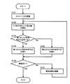
まず、ステップS101では、ECU4は、係合要素72に付与するストローク力を調整する処理を行う。具体的には、ECU4は、ドグ部作用トルクの推定の精度を向上させるべく、係合要素72に付与するストローク力を低減させる。例えば、ECU4は、予め定めたストローク力まで低減させる。この場合、ECU4は、ストローク力を変化可能に構成された構成部に対する制御を行う。そして、処理はステップS102に進む。
First, in step S <b> 101, the
ステップS102では、ECU4は、ドグ部作用トルク(絶対値)の推定を行う。具体的には、ECU4は、上記のようにストローク力を調整した後において、係合要素72におけるストロークの変化量から解放ストローク時間を求め、求められた解放ストローク時間に基づいてドグ部作用トルクの推定を行う。詳しくは、ECU4は、ストローク量センサ40を利用して係合要素72のストローク変化量を検出して、当該ストローク変化量から解放ストローク時間を求める。そして、ECU4は、例えば予め求められたドグ部作用トルクと解放ストローク時間との関係(図5など参照)などに基づいて、求められた解放ストローク時間に対応するドグ部作用トルクを得る。このような処理後、処理はステップS103に進む。
In step S102, the
ステップS103〜S105では、ECU4は、ステップS102で推定されたドグ部作用トルクが絶対値で得られるため、当該ドグ部作用トルクの符号(正負)を判定するための処理を行う。まず、ステップS103では、ECU4は、ドグ部作用トルクの大きさに応じて、第1のトルク符号判定方法を行うか否かを判定する。具体的には、ECU4は、推定されたドグ部作用トルクが、第1のトルク符号判定方法を実行すべきとして定めた領域(例えば、図6中の領域D2)内にあるか否かを判定する。詳しくは、推定されたドグ部作用トルクの絶対値が、スティックトルク以下であり且つ所定トルク以上であるか否かを判定する。
In steps S103 to S105, the
推定されたドグ部作用トルクが第1のトルク符号判定方法を実行すべきとして定めた領域内にある場合には、ECU4は、第1のトルク符号判定方法を行うべきと判定し(ステップS103;Yes)、処理はステップS104に進む。ステップS104では、ECU4は、第1のトルク符号判定方法を実行する。具体的には、ECU4は、MGトルクを付与させることでドグ部作用トルクを変化させた際の解放ストローク時間の変化(増減)から、ドグ部作用トルクの符号を判定する。この場合、ECU4は、解放ストローク時間の減少を単位時間当たりのストローク変化量の増加で検出し、解放ストローク時間の増加を単位時間当たりのストローク変化量の減少で検出する。そして、処理はステップS106に進む。
If the estimated dog portion acting torque is within the region determined to execute the first torque code determination method, the
これに対して、推定されたドグ部作用トルクが第1のトルク符号判定方法を実行すべきとして定めた領域内にない場合には、ECU4は、第1のトルク符号判定方法を行うべきでないと判定し(ステップS103;No)、処理はステップS105に進む。ステップS105では、ECU4は、第2のトルク符号判定方法を実行する。具体的には、ECU4は、係合要素72におけるバックラッシ相当の位相変化量から、ドグ部作用トルクの符号を判定する。詳しくは、ECU4は、ドグ歯におけるバックラッシ相当の位相の偏りを回転センサ41で検出することにより、ドグ部作用トルクの符号を判定する。そして、処理はステップS106に進む。
On the other hand, if the estimated dog portion applied torque is not within the region determined to execute the first torque code determination method, the
ステップS106では、ECU4は、ドグブレーキ部7の解放が完了したか否かを判定する。具体的には、ECU4は、ストローク量センサ40の検出値に基づいて、係合要素72のストローク量が解放判定値に達したか否かを判定する。解放が完了している場合(ステップS106;Yes)、処理は終了する。これに対して、解放が完了していない場合(ステップS106;No)、処理はステップS107に進む。
In step S106, the
ステップS107では、ECU4は、上記したように推定されたドグ部作用トルクに基づいて解放時間の調整を行う。具体的には、ECU4は、目標解放時間へ収束させるべく、推定されたドグ部作用トルクに基づいて、MGトルク及びエンジントルクの少なくとも一方を制御してドグ部作用トルクを調整したり、ストローク力を調整したりする制御を行う。つまり、ECU4は、推定されたドグ部作用トルクに基づいて、ドグ部作用トルクやストローク力を制御することで解放ストローク時間を調整することによって(言い換えるとストローク変化量を調整することによって)、目標解放時間への収束を図る。例えば、ECU4は、MGトルクを調整してドグ部作用トルクを小さくしたり、ストローク力を大きくしたりすることで、解放ストローク時間を短くする。これに対して、ECU4は、MGトルクを調整してドグ部作用トルクを大きくしたり、ストローク力を小さくしたりすることで、解放ストローク時間を長くする。ステップS107の処理が終了すると、処理はステップS102に戻り、上記したような処理を再度実行する。
In step S107, the
以上説明した処理によれば、解放時間のばらつきを低減することができると共に、変速ショックを低減することができる。 According to the processing described above, variation in release time can be reduced and shift shock can be reduced.
[変形例]
上記では、ストローク量センサ40を用いて係合要素72のストローク量を検出する例を示したが、ストローク量センサ40の代わりに接点スイッチを用いてストローク量を取得しても良い。更に他の例では、回転センサ41が検出する位相情報から、ストローク量を取得することとしても良い。この方法は、ストローク量が変化することに伴う物理量の変化を検出することに相当する。例えばドグ歯の接触面に勾配をつけた場合などには、回転センサ41で検出される位相情報でもストローク量情報と同等の情報として利用でき、制御構築が可能であるからである。
[Modification]
In the above, an example in which the stroke amount of the
また、上記では、回転センサ41によって位相変化を検出する例を示したが、これに限定はされない。他の例では、回転センサ41を用いずに、第1のモータジェネレータMG1における位相(レゾルバより取得される)及び第2のモータジェネレータMG2における位相(レゾルバより取得される)に基づき、ギア比より、このような位相変化を求めることができる。
Moreover, although the example which detects a phase change with the
また、本発明は、ドグ部作用トルクが付与されて回転可能に構成された被係合要素71と、ストローク可能に構成された係合要素72とを備えてなるドグブレーキ部7に対する適用に限定されない。本発明は、ドグ部作用トルクが付与されて回転可能に構成されると共にストローク可能に構成された被係合要素を有するドグブレーキ部に対しても適用可能である。つまり、回転要素がストローク可能に構成されたタイプのドグブレーキ部に対しても適用可能である。
Further, the present invention is not limited to application to the dog brake portion 7 including the engaged element 71 configured to be rotatable by being applied with the dog portion operating torque and the engaging
また、本発明は、回転可能に構成された被係合要素71と、回転不能に構成された係合要素72とを備えてなるドグブレーキ部7に対する適用に限定されない。つまり、回転要素と固定要素とを備え、ブレーキとしての役割を果たす噛合機構に対する適用に限定されない。本発明は、両方の要素が回転可能に構成された噛合機構に対しても適用可能である。つまり、回転要素同士を噛み合わせるように構成されたクラッチ(ドグクラッチ)としての役割を果たす噛合機構に対しても適用可能である。例えば、本発明は、回転要素同士を噛み合わせるように構成された噛合機構を利用する、マルチモードにて変速を行うハイブリッド車両に対しても適用することができる。
Further, the present invention is not limited to the application to the dog brake portion 7 including the engaged element 71 configured to be rotatable and the engaging
更に、本発明は、係合要素及び被係合要素のいずれか一方にモータジェネレータが連結された構成に適用は限定されず、係合要素及び被係合要素の両方にモータジェネレータが連結された構成にも適用することができる。 Further, the present invention is not limited to the configuration in which the motor generator is connected to either the engaging element or the engaged element, and the motor generator is connected to both the engaging element and the engaged element. It can also be applied to configurations.
1 エンジン
3 出力軸
4 ECU
7 ドグブレーキ部
20 動力分配機構
31 インバータ
32、34 コンバータ
33 HVバッテリ
40 ストローク量センサ
41 回転センサ
71 被係合要素
72 係合要素
MG1 第1のモータジェネレータ
MG2 第2のモータジェネレータ
1
7
Claims (7)
前記噛合機構の係合動作時及び解放動作時において、前記ドグ歯におけるストロークの変化量から前記解放に要する時間を求め、求められた前記解放に要する時間から前記ドグ歯に作用するトルクを推定するトルク推定手段を備えることを特徴とする車両の駆動制御装置。 A meshing mechanism having an engagement element and an engaged element provided with a plurality of dog teeth, and performing engagement / release by stroking at least one of the engagement elements and the engaged elements. A vehicle drive control device comprising:
During the engagement operation and the release operation of the meshing mechanism, the time required for the release is obtained from the amount of change in the stroke of the dog teeth, and the torque acting on the dog teeth is estimated from the obtained time required for the release. A drive control apparatus for a vehicle, comprising torque estimation means.
前記モータジェネレータからトルクを付与させることで前記ドグ歯に作用するトルクを変化させた状態での前記ストロークの変化量から、前記トルク推定手段によって推定された前記ドグ歯に作用するトルクの正負を判定する第1のトルク符号判定方法を実行するトルク符号判定手段を更に備える請求項1又は2に記載の車両の駆動制御装置。 A motor generator is connected to at least one of the engaging element and the engaged element,
The sign of the torque acting on the dog tooth estimated by the torque estimating means is determined from the amount of change in the stroke in a state where the torque acting on the dog tooth is changed by applying torque from the motor generator. The vehicle drive control device according to claim 1, further comprising torque code determination means for executing the first torque code determination method.
前記モータジェネレータからトルクを付与させて前記ドグ歯に所定トルクを作用させた状態で、前記ドグ歯をストロークさせることにより、前記ストローク時における摺動部分の摩擦係数を算出する摩擦係数算出手段を更に備える請求項1乃至5のいずれか一項に記載の車両の駆動制御装置。 A motor generator is connected to at least one of the engaging element and the engaged element,
Friction coefficient calculating means for calculating a friction coefficient of a sliding portion during the stroke by stroking the dog teeth while applying a predetermined torque to the dog teeth by applying torque from the motor generator. A vehicle drive control device according to any one of claims 1 to 5.
Priority Applications (1)
| Application Number | Priority Date | Filing Date | Title |
|---|---|---|---|
| JP2008259641A JP5187111B2 (en) | 2008-10-06 | 2008-10-06 | Vehicle drive control device |
Applications Claiming Priority (1)
| Application Number | Priority Date | Filing Date | Title |
|---|---|---|---|
| JP2008259641A JP5187111B2 (en) | 2008-10-06 | 2008-10-06 | Vehicle drive control device |
Publications (2)
| Publication Number | Publication Date |
|---|---|
| JP2010089575A true JP2010089575A (en) | 2010-04-22 |
| JP5187111B2 JP5187111B2 (en) | 2013-04-24 |
Family
ID=42252727
Family Applications (1)
| Application Number | Title | Priority Date | Filing Date |
|---|---|---|---|
| JP2008259641A Expired - Fee Related JP5187111B2 (en) | 2008-10-06 | 2008-10-06 | Vehicle drive control device |
Country Status (1)
| Country | Link |
|---|---|
| JP (1) | JP5187111B2 (en) |
Cited By (8)
| Publication number | Priority date | Publication date | Assignee | Title |
|---|---|---|---|---|
| JP2012076539A (en) * | 2010-09-30 | 2012-04-19 | Hitachi Nico Transmission Co Ltd | Method and device for control of power transmission system for vehicle |
| JP2012081811A (en) * | 2010-10-08 | 2012-04-26 | Mitsubishi Motors Corp | Hybrid vehicle clutch control device |
| WO2013129053A1 (en) | 2012-02-29 | 2013-09-06 | 日産自動車株式会社 | Vehicle shift control device |
| JP2015089787A (en) * | 2013-11-07 | 2015-05-11 | トヨタ自動車株式会社 | Hybrid-vehicular control apparatus |
| WO2015136356A1 (en) | 2014-03-13 | 2015-09-17 | Toyota Jidosha Kabushiki Kaisha | Control apparatus for hybrid vehicle |
| JP2016135626A (en) * | 2015-01-23 | 2016-07-28 | トヨタ自動車株式会社 | Control device of gearing-type engagement device |
| JP2019093913A (en) * | 2017-11-22 | 2019-06-20 | トヨタ自動車株式会社 | Control device of transmission |
| JP2020199964A (en) * | 2019-06-12 | 2020-12-17 | トヨタ自動車株式会社 | Control device for hybrid vehicle |
Citations (6)
| Publication number | Priority date | Publication date | Assignee | Title |
|---|---|---|---|---|
| JP2000313250A (en) * | 1999-04-28 | 2000-11-14 | Hitachi Ltd | Automotive control device |
| JP2002005204A (en) * | 2000-06-23 | 2002-01-09 | Hitachi Ltd | Control unit for automobile, method for controlling automobile, and transmission |
| JP2004345527A (en) * | 2003-05-22 | 2004-12-09 | Toyota Motor Corp | Driving device of hybrid car |
| JP2005304229A (en) * | 2004-04-14 | 2005-10-27 | Nissan Motor Co Ltd | Control device for coping with motor failure of hybrid vehicle |
| JP2006038136A (en) * | 2004-07-28 | 2006-02-09 | Toyota Motor Corp | Driving device |
| JP2006083919A (en) * | 2004-09-15 | 2006-03-30 | Toyota Motor Corp | Control device of vehicle |
-
2008
- 2008-10-06 JP JP2008259641A patent/JP5187111B2/en not_active Expired - Fee Related
Patent Citations (6)
| Publication number | Priority date | Publication date | Assignee | Title |
|---|---|---|---|---|
| JP2000313250A (en) * | 1999-04-28 | 2000-11-14 | Hitachi Ltd | Automotive control device |
| JP2002005204A (en) * | 2000-06-23 | 2002-01-09 | Hitachi Ltd | Control unit for automobile, method for controlling automobile, and transmission |
| JP2004345527A (en) * | 2003-05-22 | 2004-12-09 | Toyota Motor Corp | Driving device of hybrid car |
| JP2005304229A (en) * | 2004-04-14 | 2005-10-27 | Nissan Motor Co Ltd | Control device for coping with motor failure of hybrid vehicle |
| JP2006038136A (en) * | 2004-07-28 | 2006-02-09 | Toyota Motor Corp | Driving device |
| JP2006083919A (en) * | 2004-09-15 | 2006-03-30 | Toyota Motor Corp | Control device of vehicle |
Cited By (8)
| Publication number | Priority date | Publication date | Assignee | Title |
|---|---|---|---|---|
| JP2012076539A (en) * | 2010-09-30 | 2012-04-19 | Hitachi Nico Transmission Co Ltd | Method and device for control of power transmission system for vehicle |
| JP2012081811A (en) * | 2010-10-08 | 2012-04-26 | Mitsubishi Motors Corp | Hybrid vehicle clutch control device |
| WO2013129053A1 (en) | 2012-02-29 | 2013-09-06 | 日産自動車株式会社 | Vehicle shift control device |
| JP2015089787A (en) * | 2013-11-07 | 2015-05-11 | トヨタ自動車株式会社 | Hybrid-vehicular control apparatus |
| WO2015136356A1 (en) | 2014-03-13 | 2015-09-17 | Toyota Jidosha Kabushiki Kaisha | Control apparatus for hybrid vehicle |
| JP2016135626A (en) * | 2015-01-23 | 2016-07-28 | トヨタ自動車株式会社 | Control device of gearing-type engagement device |
| JP2019093913A (en) * | 2017-11-22 | 2019-06-20 | トヨタ自動車株式会社 | Control device of transmission |
| JP2020199964A (en) * | 2019-06-12 | 2020-12-17 | トヨタ自動車株式会社 | Control device for hybrid vehicle |
Also Published As
| Publication number | Publication date |
|---|---|
| JP5187111B2 (en) | 2013-04-24 |
Similar Documents
| Publication | Publication Date | Title |
|---|---|---|
| JP5187111B2 (en) | Vehicle drive control device | |
| JP4329856B2 (en) | Vehicle drive control device | |
| EP2581284B1 (en) | Hybrid vehicle and method of controlling thereof | |
| JP4111140B2 (en) | Electric vehicle drive control device and electric vehicle drive control method | |
| JP4236084B2 (en) | Hybrid vehicle drive control device, hybrid vehicle drive control method, and hybrid vehicle drive control program | |
| US9014899B2 (en) | Method and system for controlling downshift for hybrid vehicle | |
| US9415675B2 (en) | Hybrid vehicle driving device | |
| JP4390005B2 (en) | Vehicle control device | |
| JP2013103516A (en) | Vehicle and control method for vehicle | |
| JP6245234B2 (en) | Vehicle drive device | |
| CN102753804B (en) | Device for estimating changes in target objects | |
| JP3900105B2 (en) | Hybrid vehicle drive control apparatus, hybrid vehicle drive control method, and program thereof | |
| JP4888300B2 (en) | Motor torque control device | |
| JP6048154B2 (en) | Power transmission device and hybrid system for hybrid vehicle | |
| JP2005220873A (en) | Device and method for controlling vehicle driving | |
| JP6344338B2 (en) | Hybrid vehicle | |
| JP5035034B2 (en) | Clutch control device | |
| JP6030478B2 (en) | Vehicle control device | |
| JP5024101B2 (en) | Vehicle drive control device | |
| JP6048101B2 (en) | Hybrid vehicle drive device | |
| JP2013103514A (en) | Vehicle and control method for the same | |
| JP2005117779A (en) | Controller of hybrid vehicle | |
| JP5758778B2 (en) | Vehicle and vehicle control method | |
| JP6064877B2 (en) | Hybrid vehicle engine start control device | |
| JP4941255B2 (en) | Drive device for hybrid vehicle |
Legal Events
| Date | Code | Title | Description |
|---|---|---|---|
| A621 | Written request for application examination |
Free format text: JAPANESE INTERMEDIATE CODE: A621 Effective date: 20101227 |
|
| A977 | Report on retrieval |
Free format text: JAPANESE INTERMEDIATE CODE: A971007 Effective date: 20120831 |
|
| A131 | Notification of reasons for refusal |
Free format text: JAPANESE INTERMEDIATE CODE: A131 Effective date: 20120911 |
|
| A521 | Request for written amendment filed |
Free format text: JAPANESE INTERMEDIATE CODE: A523 Effective date: 20121002 |
|
| TRDD | Decision of grant or rejection written | ||
| A01 | Written decision to grant a patent or to grant a registration (utility model) |
Free format text: JAPANESE INTERMEDIATE CODE: A01 Effective date: 20121225 |
|
| A61 | First payment of annual fees (during grant procedure) |
Free format text: JAPANESE INTERMEDIATE CODE: A61 Effective date: 20130107 |
|
| FPAY | Renewal fee payment (event date is renewal date of database) |
Free format text: PAYMENT UNTIL: 20160201 Year of fee payment: 3 |
|
| R151 | Written notification of patent or utility model registration |
Ref document number: 5187111 Country of ref document: JP Free format text: JAPANESE INTERMEDIATE CODE: R151 |
|
| FPAY | Renewal fee payment (event date is renewal date of database) |
Free format text: PAYMENT UNTIL: 20160201 Year of fee payment: 3 |
|
| LAPS | Cancellation because of no payment of annual fees |