JP2010088217A - Grommet - Google Patents
Grommet Download PDFInfo
- Publication number
- JP2010088217A JP2010088217A JP2008254989A JP2008254989A JP2010088217A JP 2010088217 A JP2010088217 A JP 2010088217A JP 2008254989 A JP2008254989 A JP 2008254989A JP 2008254989 A JP2008254989 A JP 2008254989A JP 2010088217 A JP2010088217 A JP 2010088217A
- Authority
- JP
- Japan
- Prior art keywords
- cylindrical portion
- diameter cylindrical
- flap
- grommet
- small
- Prior art date
- Legal status (The legal status is an assumption and is not a legal conclusion. Google has not performed a legal analysis and makes no representation as to the accuracy of the status listed.)
- Granted
Links
Images


Abstract
Description
本発明は、自動車の車体に設けられた貫通穴に、ワイヤハーネスを挿通した状態で取り付けるグロメットに関し、特に、遮音部によるシール構造を備えるものにおいて、さらなる遮音性向上を図るものである。 The present invention relates to a grommet that is attached in a state where a wire harness is inserted into a through hole provided in a vehicle body of an automobile, and in particular, in a case having a seal structure with a sound insulation portion, further improving sound insulation.
自動車のエンジンルームと車室とを仕切る車体パネルに設けた貫通穴にワイヤハーネスを貫通させて配索する場合、ゴムあるいはエストラマー製のグロメットを介在させて、車室への防水、防塵、遮音等を図っている。なかでも、遮音部を有するグロメットは、エンジンルームの騒音が車室内に伝わることを防止、抑制するものとして広く用いられている。 When wiring the wiring harness through the through hole provided in the vehicle body panel that separates the engine room from the vehicle compartment, rubber or elastomer grommet is interposed to waterproof, dustproof, soundproof, etc. I am trying. Especially, the grommet which has a sound-insulation part is widely used as what prevents and suppresses the noise of an engine room being transmitted to a vehicle interior.
図12は、この種のグロメットとして、登録実用新案第3049904号で示されたグロメットである。このグロメット1は、ワイヤハーネスWを密着させて挿通する両端の小径筒部2、3を大径筒部4を介して軸線方向に連続させ、大径筒部4の外周面に車体パネル7の貫通穴7aと嵌合する車体係止凹部5を形成すると共に、該外周面から遮音用フラップ6を突設している。該グロメット1は、遮音用フラップ6の周縁部先端を、車体パネル7に積層した遮音材8の表面に当接させて該遮音材8の貫通穴8aをシールすると共に、前記フラップ6と大径筒部4と遮音材8の貫通穴8aの内周面とで囲まれた空間に密閉された空気層9を形成することで遮音性を高めている。
FIG. 12 shows a grommet shown in registered utility model No. 3049904 as this type of grommet. The
しかしながら、近年は車室内における高度な静寂性が求められる傾向にあるため、グロメットの遮音性能のさらなる向上が必要となっている。 However, in recent years, since there is a tendency to require a high degree of silence in the passenger compartment, it is necessary to further improve the sound insulation performance of the grommet.
本発明は前記問題に鑑みてなされたもので、遮音部を備えるグロメットにおいて、遮音性能をさらに高めることを課題としている。 This invention is made | formed in view of the said problem, and makes it a subject to further improve a sound insulation performance in a grommet provided with a sound insulation part.
前記課題を解決するために、本発明は、車両に配索するワイヤハーネスを密着させて挿通する小径筒部と、該小径筒部の一端と連続する拡径筒部と、該拡径筒部の大径側先端と連続する大径筒部と、該大径筒部の外周面に設けた車体パネルの貫通穴に嵌合する環状の車体係止凹部とを備えた弾性材からなるグロメットであって、
前記小径筒部の外周面には、軸線方向に間隔をあけて前記拡径筒部側へ向けて円錐状に突出させた第1フラップと第2フラップとを備え、
前記第1フラップは、その周縁を前記車体パネルの一面側に積層した遮音材の表面に前記貫通穴を囲むように当接する大きさとし、前記第2フラップは、その周縁が前記遮音材と当接している第1フラップに当接し、又は第2フラップの周縁が前記遮音材に直接当接する大きさとし、前記車体パネルに取り付けた状態で、前記第1フラップと前記拡径筒部と前記大径筒部と前記遮音材の開口周縁に囲まれた第1吸音用空気層と、該第1フラップと前記第2フラップと前記小径筒部に囲まれた第2吸音用空気層とを設ける構成としていることを特徴とするグロメットを提供している。
In order to solve the above-described problems, the present invention provides a small-diameter cylindrical portion that is inserted in close contact with a wire harness arranged in a vehicle, an enlarged-diameter cylindrical portion that is continuous with one end of the small-diameter cylindrical portion, and the enlarged-diameter cylindrical portion. A grommet made of an elastic material including a large-diameter cylindrical portion that is continuous with the large-diameter tip and an annular vehicle body locking recess that fits into a through-hole of a vehicle body panel provided on the outer peripheral surface of the large-diameter cylindrical portion. There,
The outer peripheral surface of the small-diameter cylindrical portion includes a first flap and a second flap that protrude in a conical shape with an interval in the axial direction toward the enlarged-diameter cylindrical portion side,
The first flap is sized to abut on the surface of the sound insulating material laminated on one side of the vehicle body panel so as to surround the through hole, and the second flap has a periphery abutting on the sound insulating material. The first flap, the enlarged-diameter cylindrical portion, and the large-diameter cylinder are attached to the vehicle body panel in such a size that the first flap is in contact with each other or the peripheral edge of the second flap is in direct contact with the sound insulating material. And a first sound-absorbing air layer surrounded by the opening periphery of the sound insulating material, and a second sound-absorbing air layer surrounded by the first flap, the second flap, and the small-diameter cylindrical portion. The grommet characterized by this is provided.
このように、グロメットの小径筒部の外周面から軸線方向に間隔をあけて2枚のフラップを突設することにより、該グロメットを車体パネルの貫通穴に取り付けたときに、該貫通穴部分において、車体パネルを挟んだ一面側と他面側との間に前記2つの密閉された吸音用空気層を形成でき、この2つの吸音用空気層と2枚のフラップを介して貫通穴を封鎖できるため、1枚のフラップと1つの空気層で貫通穴を封鎖する従来のグロメットよりもさらに遮音性能を向上させることができる。 Thus, by projecting two flaps at an interval in the axial direction from the outer peripheral surface of the small diameter cylindrical portion of the grommet, when the grommet is attached to the through hole of the vehicle body panel, The two sealed sound-absorbing air layers can be formed between the one side and the other side of the vehicle body panel, and the through holes can be sealed through the two sound-absorbing air layers and two flaps. Therefore, the sound insulation performance can be further improved as compared with the conventional grommet that seals the through hole with one flap and one air layer.
さらに、本発明は、車両に配索するワイヤハーネスを密着させて挿通する小径筒部と、該小径筒部の一端と連続する拡径筒部と、該拡径筒部の大径側先端と連続する大径筒部と、該大径筒部の外周面に設けた車体パネルの貫通穴に嵌合する環状の車体係止凹部とを備えた弾性材からなるグロメットであって、
前記小径筒部に取り付ける後付部材を備え、該後付部材は前記本体側小径筒部に連結又は外嵌する後付側小径筒部と、該後付側小径筒部の外周面より軸線方向に間隔をあけて円錐状に突出させた第1フラップと第2フラップを備え、
前記第1フラップは、その周縁を前記車体パネルの一面側に積層した遮音材の表面に前記貫通穴を囲むように当接する大きさとし、前記第2フラップは、その周縁が前記遮音材と当接している第1フラップに当接し又は第2フラップの周縁が前記遮音材に直接当接する大きさとし、前記車体パネルに取り付けた状態で、前記第1フラップと前記拡径筒部と前記大径筒部と前記遮音材の開口周縁に囲まれた第1吸音用空気層と、該第1フラップと前記第2フラップと前記後付側小径筒部に囲まれた第2吸音用空気層とを設ける構成としていることを特徴とするグロメットを提供している。
Further, the present invention provides a small-diameter cylindrical portion that is inserted in close contact with a wire harness that is routed in a vehicle, an enlarged-diameter cylindrical portion that is continuous with one end of the small-diameter cylindrical portion, and a large-diameter-side tip of the enlarged-diameter cylindrical portion; A grommet made of an elastic material having a continuous large-diameter cylindrical portion and an annular vehicle body locking recess that fits into a through-hole of a vehicle body panel provided on the outer peripheral surface of the large-diameter cylindrical portion,
A retrofit member attached to the small-diameter cylindrical portion is provided, and the retrofit member is connected to or externally attached to the main body-side small-diameter cylindrical portion, and an axial direction from the outer peripheral surface of the retrofit-side small-diameter cylindrical portion. A first flap and a second flap projecting in a conical shape with a gap therebetween,
The first flap is sized to abut on the surface of the sound insulating material laminated on one side of the vehicle body panel so as to surround the through hole, and the second flap has a periphery abutting on the sound insulating material. The first flap, the enlarged-diameter cylindrical portion, and the large-diameter cylindrical portion in a state where the first flap is in contact with the first flap or the peripheral edge of the second flap is in direct contact with the sound insulating material and attached to the vehicle body panel. And a first sound-absorbing air layer surrounded by the opening periphery of the sound-insulating material, and a second sound-absorbing air layer surrounded by the first flap, the second flap, and the rear-side small-diameter cylindrical portion. It provides a grommet characterized by that.
このように第1フラップと第2フラップを前記後付部材に備え、該後付部材をグロメットの本体側小径筒部に取り付ける構成とすることにより、グロメットにフラップを一体成形するときほどの高度な技術を必要とせず、容易に製造することができる。 As described above, the first flap and the second flap are provided on the retrofitting member, and the retrofitting member is attached to the main body side small-diameter cylindrical portion of the grommet so that the flap is integrated with the grommet. It can be manufactured easily without requiring any technology.
前記後付部材は、前記後付側小径筒部の後端面と前記第1フラップの内周面とを連続させて断面く字状の段状凹部を形成すると共に、該後付部材をグロメットに取り付けるときに、前記段状凹部の底面となる前記後付側小径筒部の後端面を、前記本体側小径筒部の開口側端面又は該本体側小径筒部の外周面より突設した被突き当てリブに突き当てて位置決めできる構成としていることが好ましい。 The retrofitting member forms a step-shaped recess having a square cross section by connecting the rear end surface of the retrofitting side small diameter cylindrical portion and the inner peripheral surface of the first flap, and the retrofitting member is used as a grommet. When attached, the rear end surface of the rear-side small-diameter cylindrical portion serving as the bottom surface of the stepped recess is projected from the opening-side end surface of the main-body-side small-diameter cylindrical portion or the outer peripheral surface of the main-body-side small-diameter cylindrical portion. It is preferable that the configuration is such that it can be positioned against the abutment rib.
このように、グロメットの本体側と後付部材側に、互いに突き当てて位置決めできる構造を備えることにより、後付部材の取付時に該後付部材のグロメット本体に対する位置決めを容易かつ正確に行うことができる。よって、後付部材を本体側に深く嵌め込みすぎて前記第1吸音空気層を潰してしまう、あるいは、浅く嵌め込みすぎて第1フラップが前記遮音材の表面に当接せず浮いてしまうことに因る空気層の形成不良を防止し、常に安定した優れた遮音性を機能させることができる。 In this way, by providing a structure that can be positioned by abutting each other on the main body side and the rear attachment member side of the grommet, the rear attachment member can be easily and accurately positioned relative to the grommet main body when the rear attachment member is attached. it can. Therefore, the retrofitting member is too deeply fitted into the main body side to crush the first sound-absorbing air layer, or is too shallow and the first flap floats without coming into contact with the surface of the sound insulating material. It is possible to prevent a poor formation of the air layer and to function a stable sound insulation that is always stable.
グロメット前記本体側小径筒部には、前記後付部材の前方への抜けを防止する突起を形成してもよい。
具体的には、後付部材の小径筒部を本体側小径筒部に外嵌して後付部材をグロメット本体に取り付ける構成とすると共に、本体側小径筒部の開口端(前端)より外側に被突き当てリブを突設し、後付側小径筒部の前端面、あるいは、該前端より外側に突設した突き当てリブを前記被突き当てリブの後端面に突き当てる。これにより、後付部材がグロメット本体への正常な取付位置よりも前方に位置ズレすることを防止できる。
A grommet may be formed on the main body side small-diameter cylindrical portion to prevent the retrofitting member from slipping forward.
Specifically, the small-diameter cylindrical portion of the retrofitting member is externally fitted to the main body-side small-diameter cylindrical portion, and the retrofitting member is attached to the grommet main body, and outside the opening end (front end) of the main-body-side small-diameter cylindrical portion. The abutting rib is projected, and the abutting rib projecting outward from the front end of the small diameter cylindrical portion at the rear side or the abutting rib is abutted against the rear end surface of the abutting rib. Thereby, it can prevent that a retrofitting member shifts ahead rather than the normal attachment position to a grommet main body.
上述したように、本発明のグロメットは、二重フラップ構造とすることにより、車体パネルの貫通穴部分に2つの密閉された吸音用空気層を形成することができ、この2つの吸音用空気層と2枚のフラップを介して前記貫通穴をシールすることができる。よって、1枚のフラップとで1つの吸音用空気層によって貫通穴をシールする従来のグロメットに比して、遮音性能をさらに高めることができる。 As described above, the grommet of the present invention has a double flap structure, so that two sealed sound absorbing air layers can be formed in the through-hole portion of the vehicle body panel, and these two sound absorbing air layers are formed. And the through hole can be sealed through two flaps. Therefore, compared with the conventional grommet which seals a through-hole with one sound absorption air layer with one flap, sound insulation performance can further be improved.
また、前記2枚のフラップを後付部材に備え、該後付部材をグロメットの本体側小径筒部に取り付ける構成とすることにより、グロメットにフラップを一体成形する技術よりも易しい技術で容易に製造することができる。 In addition, the two flaps are provided in a retrofitting member, and the retrofitting member is attached to the main body side small-diameter cylindrical portion of the grommet so that it can be easily manufactured by a technique that is easier than the technique of integrally forming the flap on the grommet. can do.
以下、本発明の実施形態を図面を参照して説明する。
いずれの実施形態も、図2に示すように、自動車のエンジンルームXと車室Yとを仕切る車体パネル60(ダッシュパネル)に設けた貫通穴61を挿通するワイヤハーネス70に装着して前記貫通穴61に取り付けられるグロメットに本発明を適用している。車体パネル60の車室Y側面には遮音材62を積層し、該遮音材62には車体パネル60の貫通穴61と連通する内側貫通穴63を設けている。
Hereinafter, embodiments of the present invention will be described with reference to the drawings.
In any of the embodiments, as shown in FIG. 2, the through-
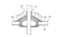
図1および図2に、本発明の第1実施形態に係るグロメット10を示す。
グロメット10はゴム又はエストラマーからなる一体成形品である。図1に示すように、小径筒部11と、該小径筒部11の一端と連続する拡径筒部12と、該拡径筒部12の大径側先端と連続する大径筒部13と、該大径筒部13の先端内周面から突設する閉鎖壁部14とを備え、前記大径筒部13の外周面には、車体パネル60の前記貫通穴61の周縁部と嵌合する環状の車体係止凹部17を凹設している。
1 and 2 show a
The
前記閉鎖壁部14の中央には、ワイヤハーネス70を挿通するためのハーネス貫通穴15を設けており、連続して設ける小径筒部11、拡径筒部12、大径筒部13、ハーネス貫通穴15の同一軸線に沿った中空部をワイヤハーネス挿通路16としている。前記小径筒部11とハーネス貫通穴15は、ワイヤハーネス挿通路16に挿通したワイヤハーネス70の両端部外周面にそれぞれ密嵌する構成としている。
A harness through
前記小径筒部11の外周面からは、軸線方向に間隔をあけて、拡径筒部12に向けて円錐状に突出させた遮音用の第1フラップ18と第2フラップ19を突設している。
前記第1フラップ18は、図2に示すように、その先端周縁部18aが、グロメット10を車体パネル60の貫通穴61に取り付けた状態において、該車体パネル60に積層した前記遮音材62の前記内側貫通穴63を囲むように該遮音材62の表面に当接する大きさとしている。
前記第2フラップ19は、その先端周縁部19aが、遮音材62に当接した前記第1フラップ18の先端側外周面に当接する大きさとしている。
From the outer peripheral surface of the small-diameter
As shown in FIG. 2, the
The
前記構成のグロメット10は、図2に示すように、ワイヤハーネス70を挿通して車体パネル60の貫通穴61に取り付けられた状態において、遮音材62の内側貫通穴63の内周面63aとグロメット10と外周面との隙間を前記第1フラップ18でシールすることができるうえ、第1フラップ18と小径筒部11と拡径筒部12と大径筒部13と遮音材62の前記内側貫通穴63の内周面63aとで囲まれた部分に、密閉された第1吸音用空気層S1を形成し、かつ、第1フラップ18と第2フラップ19と小径筒部11とで囲まれた部分にも密閉された第2吸音用空気層S2を形成することができる。このように、グロメット10は、第1フラップ18と第2フラップ19の二重フラップ構造により、密閉された吸音用空気層を2つに増やすことができるため、従来のグロメットよりも遮音性が向上し、車室Y側の静寂性を高めることができる。
As shown in FIG. 2, the
前記グロメット10は、図3に示す変形例1のように、第2フラップ19を第1フラップ18よりも大径とし、該第2フラップ19の先端周縁部19aを、遮音材62に当接した第1フラップ18の外側を囲むように遮音材62の表面に当接させてもよい。
In the
本変形例1においても、前記第1吸音用空気層S1に加えて、第1フラップ18と第2フラップ19と遮音材62と小径筒部11とに囲まれた部分に密閉された第2吸音用空気層S2を形成することができるため、優れた遮音性を備えることができる。
Also in the first modification, in addition to the first sound absorbing air layer S1, the second sound absorbing member sealed in a portion surrounded by the
図4乃至図6に、本発明の第2実施形態に係るグロメット20を示す。
グロメット20は、互いに別体からなるグロメット本体21と後付部材22とを連結してなる。
4 to 6 show a
The
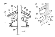
グロメット本体21は、ゴム又はエストラマーからなる一体成形品であり、図4に示すように、軸線方向に短い小径筒部(本体側小径筒部)23と、該小径筒部23の一端と連続する拡径筒部24と、該拡径筒部24の大径側先端と連続する大径筒部25と、該大径筒部25の先端内周面から突設する閉鎖壁部26とを備えている。大径筒部25の外周面には、車体パネル60の前記貫通穴61の周縁部と嵌合する環状の車体係止凹部28を凹設している。
The
前記閉鎖壁部26の中央には、ワイヤハーネス70を挿通するためのハーネス貫通穴27を設けており、該ハーネス貫通穴27と前記小径筒部23は、ワイヤハーネス70の両端部外周面にそれぞれ密嵌する構成としている。
前記本体側小径筒部23の開口側先端面23bは、グロメット本体21と後付部材22との連結時の突き当て面であり、本体側小径筒部23の軸線方向に直交する垂直面としている。
A harness through
The opening side
前記後付部材22は、ゴム又はエストラマーからなる一体成形品であり、図4に示すように、小径筒部(後付側小径筒部)31と、該小径筒部31の軸線方向一端側の外周面より円錐状に突出させた遮音用の第1フラップ32と、該第1フラップ32から軸線方向に間隔をあけた小径筒部31の軸線方向中央部の外周面より前記第1フラップ32と略平行に円錐状に突出させた遮音用の第2フラップ33とを備えている。
The retrofitting
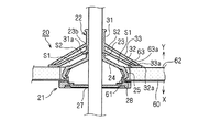
前記第1フラップ32は、図6に示すように、その先端周縁部32aが、グロメット20を車体パネル60の貫通穴61に取り付けた状態において、車体パネル60に積層した前記遮音材62の前記内側貫通穴63を囲むように該遮音材62の表面に当接する大きさとしている。
前記第2フラップ33は、その先端周縁部33aが、遮音材62に当接した前記第1フラップ32の先端側外周面に当接する大きさとしている。
As shown in FIG. 6, the
The
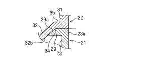
前記後付側小径筒部31のフラップ突出側の先端面31a(後端面31a)は、グロメット本体21と後付部材22との連結に際しての突き当て面となる。該突き当て面31aは、前記軸線方向に対して直交する垂直面とし、図4に示すように、この垂直な突き当て面31aと第1フラップ32の傾斜した内周面32bとを連続させて、該突き当て面31aを底面とする断面く字状の段状凹部34を形成している。
The
前記グロメット20をワイヤハーネス70に装着するに際しては、まず、図5(A)に示すように、グロメット本体21をワイヤハーネス70に挿通し、本体側小径筒部23とワイヤハーネス70とをテープ巻き(図示せず)してグロメット本体21をワイヤハーネス70に位置決め固定した後、該ワイヤハーネス70に後付部材22を挿通し、図5(B)に示すように、本体側小径筒部23の開口側先端面23bに、前記後付側小径筒部31の後端面31aを突き当てて位置決めし、本体側小径筒部23と後付側小径筒部31の中空部が連続するようにグロメット本体21と後付部材22とを連結した状態で、後付側小径筒部31とワイヤハーネス70とをテープ巻き(図示せず)して後付部材22をワイヤハーネス70に位置決め固定する。
When attaching the
このようにグロメット本体21に後付部材22を連結してなるグロメット20は、図6に示すように、車体パネル60の貫通穴61に取り付けられた状態において、後付部材22の第1フラップ32の先端周縁部32aが遮音材62の表面に当接する。これにより、該遮音材62の内側貫通穴63の内周面63aとグロメット本体21の外周面との間の隙間をシールすることができる。かつ、第1フラップ32と本体側小径筒部23と拡径筒部24と大径筒部25と遮音材62の内側貫通穴63の内周面63aとで囲まれた部分に密閉された第1吸音用空気層S1を形成する。かつ、第1フラップ32と第2フラップ33と後付側小径筒部31とで囲まれた部分にも密閉された第2吸音用空気層S2を形成することができる。よって、前記第1実施形態と同様に、従来のグロメットよりも吸音用空気層を増やすことができるため、遮音性を高めることができる。
The
また、前記グロメット20は、フラップ32、33を備えた後付部材22を、グロメット本体21とは別体としているため、グロメット本体にフラップを一体成形する場合ほどの高度な技術を必要とせず、比較的容易に製造することができる。
Further, since the
さらに、後付側小径筒部31の後端面31aと第1フラップ32の内周面32bとで断面く字状の段状凹部34を形成しているため、グロメット本体21に後付部材22を取り付けるときに、図5(B)に示すように、本体側小径筒部23の開口側先端部23aが前記段状凹部34内に収まり、この本体側小径筒部23の開口側先端面23bに後付側小径筒部31の前記後端面31aを容易かつ正確に突き当てることができる。また、本体側小径筒部23の開口側先端部23aが段状凹部34内に嵌り込む。これにより、本体側小径筒部23と後付側小径筒部31の互いの突き当て面23b、31aが位置ズレすることも防止できる。よって、グロメット本体21と後付部材22とを容易かつ正確に、隙間なく連結することができるため、作業性および品質安定性を高めることができる。
Furthermore, since the
図7に第2実施形態の変形例1を示す。
変形例1では、後付側小径筒部31の後端部よりフランジ部35を外方に突設し、該フランジ部35の外周端から第1フラップ32を突設している。また、本体側小径筒部23の開口側先端(前端)より外方に環状の被突き当てリブ29を突設している。
FIG. 7 shows a first modification of the second embodiment.
In the first modification, the
このように、後付側小径筒部31に前記フランジ部35を形成することにより、該後付側小径筒部31の後端面31aの面積を大きくでき、該後端面31aが突き当たる本体側小径筒部23の開口側先端面23bも前記被突き当てリブ29の形成により大きくなり、互いの突き当て面積を拡大できるため、前記突き当て状態を安定させ、かつ、強化することができる。
In this way, by forming the
前記被突き当てリブ29の外周面29aは、図8に示す変形例2のように、後付部材22の第1フラップ32の内周面32bに当接するようにテーパー状に突出させてもよい。これにより、グロメット本体21の開口側先端部23aを、後付部材22の前記段状凹部34内へ嵌め込んだときのフィット感が高まるため、前記突き当て状態を一層安定させ、強化することができる。
The outer
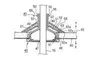
図9乃至図11に、本発明の第3実施形態に係るグロメット40を示す。
グロメット40は、互いに別体からなるグロメット本体41と後付部材42とを嵌合してなる。
9 to 11 show a
The
グロメット本体41は、ゴム又はエストラマーからなる一体成形品であり、図9に示すように、小径筒部(本体側小径筒部)43と、該小径筒部43の一端と連続する拡径筒部44と、該拡径筒部44の大径側先端と連続する大径筒部45と、該大径筒部45の先端内周面から突設する閉鎖壁部46とを備えている。大径筒部45の外周面には、車体パネル60の前記貫通穴61の周縁部と嵌合する環状の車体係止凹部48を凹設している。
The grommet
前記閉鎖壁部46の中央には、ワイヤハーネス70を挿通するためのハーネス貫通穴47を設けており、該ハーネス貫通穴47と前記小径筒部43は、ワイヤハーネス70の両端部外周面にそれぞれ密嵌する構成としている。
A harness through
前記後付部材42は、ゴム又はエストラマーからなる一体成形品であり、図9に示すように、前記本体側小径筒部43に外嵌する小径筒部(後付側小径筒部)51と、該小径筒部51の軸線方向一端側の外周面より円錐状に突出させた遮音用の第1フラップ52と、該第1フラップ52から軸線方向に間隔をあけた小径筒部51の軸線方向中央部の外周面より前記第1フラップ52と略平行に円錐状に突出させた遮音用の第2フラップ53とを備えている。
The retrofitting
前記第1フラップ52は、図11に示すように、その先端周縁部52aが、グロメット40を車体パネル60の貫通穴61に取り付けた状態において、車体パネル60に積層した前記遮音材62の前記内側貫通穴63を囲むように該遮音材62の表面に当接する大きさとしている。
前記第2フラップ53は、その先端周縁部53aが、遮音材62に当接した前記第1フラップ52の先端側外周面に当接する大きさとしている。
As shown in FIG. 11, the
The
前記後付側小径筒部51のフラップ突出側の先端面51a(後端面51a)は、後付部材42をグロメット本体41に取り付けるときの突き当て面となる。該突き当て面51aは、前記軸線方向に対して直交する垂直面とし、図9に示すように、この垂直な突き当て面51aと第1フラップ52の傾斜した内周面52bとを連続させて、該突き当て面51aを底面とする断面く字状の段状凹部54を形成している。
前記後付側小径筒部51には、その前端より外側に環状の突き当てリブ55を突設している。
The
An
前記本体側小径筒部43の外周面には、該グロメット本体41に後付部材42を正常に取り付けた状態において後付部材42の前記突き当て面51aが突き当たる被突き当て後端リブ49を環状に突設している。また、該本体側小径筒部43の開口側先端(前端)には、後付部材42の前記突き当てリブ55の前端面55aが突き当たる環状の被突き当て前端リブ50を外側に突設している。
On the outer peripheral surface of the main body side small-diameter
前記グロメット40をワイヤハーネス70に装着するに際しては、まず、図10(A)に示すように、グロメット本体41をワイヤハーネス70に挿通し、該ワイヤハーネス70の所要位置にグロメット本体41を取り付ける。
次いで、該ワイヤハーネス70に後付部材42を挿通して後付側小径筒部51を本体側小径筒部43に外嵌し、図10(B)に示すように、本体側小径筒部43の前記被突き当て後端リブ49に後付側小径筒部51の前記後端面51aを突き当てる。かつ、本体側小径筒部43の前記被突き当て前端リブ50に後付側小径筒部51の前記突き当てリブ55の前端面55aを突き当てて、グロメット本体41に後付部材42を嵌合する。
次いで、この嵌合状態で、後付側小径筒部51とワイヤハーネス70とをテープ巻き(図示せず)して後付部材42とグロメット本体41を一体にワイヤハーネス70に位置決め固定する。
When attaching the
Next, the
Next, in this fitted state, the rear attachment side small-diameter
このようにグロメット本体41に後付部材42を後付けしてなるグロメット40は、本体側小径筒部43に突設した被突き当て後端リブ49に後付側小径筒部51の後端面51aが突き当たることにより、後付部材42がグロメット本体41に対して深く嵌り込みすぎることを規制できる。また、本体側小径筒部43に突設した被突き当て前端リブ50に後付側小径筒部51の突き当てリブ55が突き当たることにより、後付部材42のグロメット本体41への嵌めこみが浅くなりすぎたり、後付部材42が前方へ抜け外れることを規制できる。よって、これらの突き当て構造により、グロメット本体41への後付部材42の取り付けを容易かつ正確に行うことができるため、作業性および品質安定性を高めることができる。
In this way, the
また、前記グロメット40が、第1吸音用空気層S1と第2吸音用空気層S2を形成して優れた遮音性を有すること、および、製造が容易であることについては、前記第2実施形態と同じである。
In addition, the
10(20、40) グロメット
11 小径筒部
12 拡径筒部
13 大径筒部
18 第1フラップ
19 第2フラップ
60 車体パネル
61 貫通穴
62 遮音材
70 ワイヤハーネス
S1 第1吸音用空気層
S2 第2吸音用空気層
10 (20, 40)
Claims (3)
前記小径筒部の外周面には、軸線方向に間隔をあけて前記拡径筒部側へ向けて円錐状に突出させた第1フラップと第2フラップとを備え、
前記第1フラップは、その周縁を前記車体パネルの一面側に積層した遮音材の表面に前記貫通穴を囲むように当接する大きさとし、前記第2フラップは、その周縁が前記遮音材と当接している第1フラップに当接し、又は第2フラップの周縁が前記遮音材に直接当接する大きさとし、前記車体パネルに取り付けた状態で、前記第1フラップと前記拡径筒部と前記大径筒部と前記遮音材の開口周縁に囲まれた第1吸音用空気層と、該第1フラップと前記第2フラップと前記小径筒部に囲まれた第2吸音用空気層とを設ける構成としていることを特徴とするグロメット。 A small-diameter cylindrical portion that is inserted in close contact with a wire harness that is routed in a vehicle, a large-diameter cylindrical portion that is continuous with one end of the small-diameter cylindrical portion, and a large-diameter cylindrical portion that is continuous with the tip on the large-diameter side of the large-diameter cylindrical portion And a grommet made of an elastic material including an annular vehicle body locking recess that fits into a through hole of a vehicle body panel provided on the outer peripheral surface of the large diameter cylindrical portion,
The outer peripheral surface of the small-diameter cylindrical portion includes a first flap and a second flap that protrude in a conical shape with an interval in the axial direction toward the enlarged-diameter cylindrical portion side,
The first flap is sized to abut on the surface of the sound insulating material laminated on one side of the vehicle body panel so as to surround the through hole, and the second flap has a periphery abutting on the sound insulating material. The first flap, the enlarged-diameter cylindrical portion, and the large-diameter cylinder are attached to the vehicle body panel in such a size that the first flap is in contact with each other or the peripheral edge of the second flap is in direct contact with the sound insulating material. And a first sound-absorbing air layer surrounded by the opening periphery of the sound insulating material, and a second sound-absorbing air layer surrounded by the first flap, the second flap, and the small-diameter cylindrical portion. Grommet characterized by that.
前記小径筒部に取り付ける後付部材を備え、該後付部材は前記本体側小径筒部に連結又は外嵌する後付側小径筒部と、該後付側小径筒部の外周面より軸線方向に間隔をあけて円錐状に突出させた第1フラップと第2フラップを備え、
前記第1フラップは、その周縁を前記車体パネルの一面側に積層した遮音材の表面に前記貫通穴を囲むように当接する大きさとし、前記第2フラップは、その周縁が前記遮音材と当接している第1フラップに当接し又は第2フラップの周縁が前記遮音材に直接当接する大きさとし、前記車体パネルに取り付けた状態で、前記第1フラップと前記拡径筒部と前記大径筒部と前記遮音材の開口周縁に囲まれた第1吸音用空気層と、該第1フラップと前記第2フラップと前記後付側小径筒部に囲まれた第2吸音用空気層とを設ける構成としていることを特徴とするグロメット。 A small-diameter cylindrical portion that is inserted in close contact with a wire harness that is routed in a vehicle, a large-diameter cylindrical portion that is continuous with one end of the small-diameter cylindrical portion, and a large-diameter cylindrical portion that is continuous with the tip on the large-diameter side of the large-diameter cylindrical portion And a grommet made of an elastic material including an annular vehicle body locking recess that fits into a through hole of a vehicle body panel provided on the outer peripheral surface of the large diameter cylindrical portion,
A retrofit member attached to the small-diameter cylindrical portion is provided, and the retrofit member is connected to or externally attached to the main body-side small-diameter cylindrical portion, and an axial direction from the outer peripheral surface of the retrofit-side small-diameter cylindrical portion. A first flap and a second flap projecting in a conical shape with a gap therebetween,
The first flap is sized to abut on the surface of the sound insulating material laminated on one side of the vehicle body panel so as to surround the through hole, and the second flap has a periphery abutting on the sound insulating material. The first flap, the enlarged-diameter cylindrical portion, and the large-diameter cylindrical portion in a state where the first flap is in contact with the first flap or the peripheral edge of the second flap is in direct contact with the sound insulating material and attached to the vehicle body panel. And a first sound-absorbing air layer surrounded by the opening periphery of the sound-insulating material, and a second sound-absorbing air layer surrounded by the first flap, the second flap, and the rear-side small-diameter cylindrical portion. Grommet characterized by that.
Priority Applications (1)
| Application Number | Priority Date | Filing Date | Title |
|---|---|---|---|
| JP2008254989A JP5163406B2 (en) | 2008-09-30 | 2008-09-30 | Grommet |
Applications Claiming Priority (1)
| Application Number | Priority Date | Filing Date | Title |
|---|---|---|---|
| JP2008254989A JP5163406B2 (en) | 2008-09-30 | 2008-09-30 | Grommet |
Publications (2)
| Publication Number | Publication Date |
|---|---|
| JP2010088217A true JP2010088217A (en) | 2010-04-15 |
| JP5163406B2 JP5163406B2 (en) | 2013-03-13 |
Family
ID=42251621
Family Applications (1)
| Application Number | Title | Priority Date | Filing Date |
|---|---|---|---|
| JP2008254989A Expired - Fee Related JP5163406B2 (en) | 2008-09-30 | 2008-09-30 | Grommet |
Country Status (1)
| Country | Link |
|---|---|
| JP (1) | JP5163406B2 (en) |
Cited By (3)
| Publication number | Priority date | Publication date | Assignee | Title |
|---|---|---|---|---|
| JP2014181461A (en) * | 2013-03-18 | 2014-09-29 | Yamaha Corp | Soundproof panel |
| CN106716759A (en) * | 2014-09-16 | 2017-05-24 | 矢崎总业株式会社 | Grommet and method for manufacturing same |
| WO2022181362A1 (en) * | 2021-02-24 | 2022-09-01 | 住友電装株式会社 | Grommet |
Citations (2)
| Publication number | Priority date | Publication date | Assignee | Title |
|---|---|---|---|---|
| JPH1047548A (en) * | 1996-08-01 | 1998-02-20 | Sumitomo Wiring Syst Ltd | Grommet and manufacture thereof |
| JPH10246333A (en) * | 1997-03-03 | 1998-09-14 | Sumitomo Wiring Syst Ltd | Grommet |
-
2008
- 2008-09-30 JP JP2008254989A patent/JP5163406B2/en not_active Expired - Fee Related
Patent Citations (2)
| Publication number | Priority date | Publication date | Assignee | Title |
|---|---|---|---|---|
| JPH1047548A (en) * | 1996-08-01 | 1998-02-20 | Sumitomo Wiring Syst Ltd | Grommet and manufacture thereof |
| JPH10246333A (en) * | 1997-03-03 | 1998-09-14 | Sumitomo Wiring Syst Ltd | Grommet |
Cited By (4)
| Publication number | Priority date | Publication date | Assignee | Title |
|---|---|---|---|---|
| JP2014181461A (en) * | 2013-03-18 | 2014-09-29 | Yamaha Corp | Soundproof panel |
| CN106716759A (en) * | 2014-09-16 | 2017-05-24 | 矢崎总业株式会社 | Grommet and method for manufacturing same |
| WO2022181362A1 (en) * | 2021-02-24 | 2022-09-01 | 住友電装株式会社 | Grommet |
| JP7344913B2 (en) | 2021-02-24 | 2023-09-14 | 住友電装株式会社 | grommet |
Also Published As
| Publication number | Publication date |
|---|---|
| JP5163406B2 (en) | 2013-03-13 |
Similar Documents
| Publication | Publication Date | Title |
|---|---|---|
| JPH1047548A (en) | Grommet and manufacture thereof | |
| JP2001333521A (en) | Grommet | |
| JP2009201204A (en) | Grommet | |
| JP2006240511A (en) | Steering cover | |
| JP2016207358A (en) | Grommet | |
| JP5163406B2 (en) | Grommet | |
| US8888174B2 (en) | Pass-through element for a motor vehicle front of dash system | |
| JP2006306306A (en) | Fender garnish structure | |
| JP2018052362A (en) | Vehicle side part structure | |
| JP2001287591A (en) | Housing | |
| JP2001245424A (en) | Grommet | |
| WO2020039854A1 (en) | Retaining member | |
| JP5163391B2 (en) | Grommet | |
| JP2008143359A (en) | Automobile interior structure | |
| JP4439657B2 (en) | Vibration isolation sound insulation | |
| JP2005324613A (en) | Grommet | |
| JP5316861B2 (en) | Vehicle speaker device | |
| JP2008155811A (en) | Vehiclular package tray | |
| JP2006284658A (en) | Sound absorbing and blocking structure | |
| CN209126795U (en) | Turning machine input shaft seal device and turning machine assembly | |
| JP6747890B2 (en) | Vehicle cushioning parts | |
| JP4617935B2 (en) | Automotive grommets | |
| JP7306211B2 (en) | vehicle front structure | |
| JP2005125949A (en) | Fuel adaptor structure | |
| WO2023175665A1 (en) | Cargo room trim and trim manufacturing method |
Legal Events
| Date | Code | Title | Description |
|---|---|---|---|
| A621 | Written request for application examination |
Free format text: JAPANESE INTERMEDIATE CODE: A621 Effective date: 20110330 |
|
| A977 | Report on retrieval |
Free format text: JAPANESE INTERMEDIATE CODE: A971007 Effective date: 20120817 |
|
| A131 | Notification of reasons for refusal |
Free format text: JAPANESE INTERMEDIATE CODE: A131 Effective date: 20120918 |
|
| A521 | Written amendment |
Free format text: JAPANESE INTERMEDIATE CODE: A523 Effective date: 20121026 |
|
| TRDD | Decision of grant or rejection written | ||
| A01 | Written decision to grant a patent or to grant a registration (utility model) |
Free format text: JAPANESE INTERMEDIATE CODE: A01 Effective date: 20121120 |
|
| A61 | First payment of annual fees (during grant procedure) |
Free format text: JAPANESE INTERMEDIATE CODE: A61 Effective date: 20121203 |
|
| FPAY | Renewal fee payment (event date is renewal date of database) |
Free format text: PAYMENT UNTIL: 20151228 Year of fee payment: 3 |
|
| R150 | Certificate of patent or registration of utility model |
Ref document number: 5163406 Country of ref document: JP Free format text: JAPANESE INTERMEDIATE CODE: R150 Free format text: JAPANESE INTERMEDIATE CODE: R150 |
|
| LAPS | Cancellation because of no payment of annual fees |