JP2010087236A - Vacuum processing device - Google Patents

Vacuum processing device Download PDF

Info

Publication number
JP2010087236A
JP2010087236A JP2008254484A JP2008254484A JP2010087236A JP 2010087236 A JP2010087236 A JP 2010087236A JP 2008254484 A JP2008254484 A JP 2008254484A JP 2008254484 A JP2008254484 A JP 2008254484A JP 2010087236 A JP2010087236 A JP 2010087236A
Authority
JP
Japan
Prior art keywords
gas
vacuum
mounting table
processing space
vacuum vessel
Prior art date
Legal status (The legal status is an assumption and is not a legal conclusion. Google has not performed a legal analysis and makes no representation as to the accuracy of the status listed.)
Granted
Application number
JP2008254484A
Other languages
Japanese (ja)
Other versions
JP5088284B2 (en
Inventor
Norihiko Tsuji
徳彦 辻
Masayuki Moroi
政幸 諸井
Jun Sawachi
淳 澤地
Susumu Kato
進 河東
Current Assignee (The listed assignees may be inaccurate. Google has not performed a legal analysis and makes no representation or warranty as to the accuracy of the list.)
Tokyo Electron Ltd
Original Assignee
Tokyo Electron Ltd
Priority date (The priority date is an assumption and is not a legal conclusion. Google has not performed a legal analysis and makes no representation as to the accuracy of the date listed.)
Filing date
Publication date
Application filed by Tokyo Electron Ltd filed Critical Tokyo Electron Ltd
Priority to JP2008254484A priority Critical patent/JP5088284B2/en
Publication of JP2010087236A publication Critical patent/JP2010087236A/en
Application granted granted Critical
Publication of JP5088284B2 publication Critical patent/JP5088284B2/en
Active legal-status Critical Current
Anticipated expiration legal-status Critical

Links

Images

Abstract

<P>PROBLEM TO BE SOLVED: To provide a vacuum processing device of which maintenance is easily conducted by opening a vacuum vessel. <P>SOLUTION: The vacuum processing device includes: a vessel body for structuring a ceiling part and side wall part of the vacuum vessel; a bottom plate part of the vacuum vessel detachably arranged on the vessel body and provided with a mounting base for mounting a substrate; a gas supply mechanism arranged on the ceiling part of the vacuum vessel and supplying processing gas to the substrate mounted on the mounting base; a support body for supporting the vessel body on a floor surface on which the vacuum processing device is arranged; a lifting part for lifting the bottom plate part between an upper position for mounting the bottom plate part on the vessel body and a lower position on a lower side of the vessel body; and a moving body which mounts the lifting part and moves along the floor surface. Trouble in removal operation of processing gas and liquid material in a pipeline, which is required in removing the ceiling part from the vacuum vessel, is omitted to facilitate maintenance. <P>COPYRIGHT: (C)2010,JPO&INPIT

Description

本発明は、真空容器内で処理ガスにより基板を処理する真空処理装置に関する。   The present invention relates to a vacuum processing apparatus for processing a substrate with a processing gas in a vacuum vessel.

半導体製造プロセスにおいては、真空容器内に形成された処理空間に設けられた載置台に基板である半導体ウエハ(以下ウエハという)を載置し、前記処理空間を排気しながら当該処理空間に処理ガスを供給する真空処理装置が用いられ、その真空処理の一例としては反応ガスを連続的に供給してウエハに成膜を行うCVD(Chemical Vapor Deposition)と呼ばれる手法が挙げられる。   In a semiconductor manufacturing process, a semiconductor wafer as a substrate (hereinafter referred to as a wafer) is mounted on a mounting table provided in a processing space formed in a vacuum vessel, and a processing gas is exhausted into the processing space while exhausting the processing space. As an example of the vacuum processing, there is a technique called CVD (Chemical Vapor Deposition) in which a reactive gas is continuously supplied to form a film on a wafer.

また、半導体製造プロセスにおけるその他の真空処理装置を用いた成膜手法としては、基板である半導体ウエハ(以下「ウエハ」という)等の表面に真空雰囲気下で第1の反応ガスを吸着させた後、供給するガスを第2の反応ガスに切り替えて、両ガスの反応により1層あるいは複数層の原子層や分子層を形成し、このサイクルを多数回行うことにより、これらの層を積層して、基板上への成膜を行うプロセスが知られている。このプロセスは、例えばALD(Atomic Layer Deposition)やMLD(Molecular Layer Deposition)などと呼ばれており、サイクル数に応じて膜厚を高精度にコントロールすることができると共に、膜質の面内均一性も良好であり、半導体デバイスの薄膜化に対応できる有効な手法である。   As another film forming method using a vacuum processing apparatus in a semiconductor manufacturing process, a first reactive gas is adsorbed on the surface of a semiconductor wafer (hereinafter referred to as “wafer”) as a substrate in a vacuum atmosphere. The gas to be supplied is switched to the second reaction gas, and one or a plurality of atomic layers and molecular layers are formed by the reaction of both gases, and these layers are stacked by repeating this cycle many times. A process for forming a film on a substrate is known. This process is called ALD (Atomic Layer Deposition) or MLD (Molecular Layer Deposition), for example, and the film thickness can be controlled with high precision according to the number of cycles, and the in-plane uniformity of the film quality is also achieved. It is a good technique that can cope with thinning of semiconductor devices.

前記ALDあるいはMLDが好適である例としては、例えばゲート酸化膜に用いられる高誘電体膜の成膜が挙げられる。一例を挙げると、シリコン酸化膜(SiO膜)を成膜する場合には、第1の反応ガス(原料ガス)として、例えばビスターシャルブチルアミノシラン(以下「BTBAS」という)ガス等が用いられ、第2の反応ガスとして酸素ガス等が用いられる。 As an example where the ALD or MLD is suitable, there is a film formation of a high dielectric film used for a gate oxide film, for example. For example, when a silicon oxide film (SiO 2 film) is formed, for example, a Vista butylaminosilane (hereinafter referred to as “BTBAS”) gas or the like is used as the first reaction gas (raw material gas). Oxygen gas or the like is used as the second reaction gas.

ウエハに均一な成膜を行うために、これらCVD、ALDあるいはMLDを実施する真空処理装置については、通常は真空容器の天井部に例えばガスシャワーヘッドなどのガス供給部が設けられ、前記載置台に載置されたウエハの中央部に対向する位置から反応ガスを供給すると共に未反応の反応ガス及び反応副生成物を処理容器の底部から排気するように構成される。例えば特許文献1にはガスシャワーヘッドを備えたCVD装置について記載されている。   In order to perform uniform film formation on a wafer, a vacuum processing apparatus that performs CVD, ALD, or MLD is usually provided with a gas supply unit such as a gas shower head on the ceiling of the vacuum vessel. The reaction gas is supplied from a position facing the central portion of the wafer placed on the substrate, and unreacted reaction gas and reaction byproducts are exhausted from the bottom of the processing vessel. For example, Patent Document 1 describes a CVD apparatus equipped with a gas shower head.

ところで成膜処理を継続すると、真空容器内において反応ガスに接触する部品にはこの反応ガスから生成した反応生成物が付着し、堆積する。そして、堆積した反応生成物をそのままにしておくと、当該反応生成物は成膜処理中に剥がれ落ちてウエハにパーティクルとして付着するので製品の歩留りが低下してしまう。このため、真空容器は例えばその側壁と天井部とが別々の部品として構成され、天井部を真空容器から取り外して、その内部を大気開放できるように構成されている。そして、装置のユーザは定期的にその天井部を取り外して、処理空間を構成する壁部、載置台及びその他の反応ガスに接触する部品を純水や有機溶剤などを用いて手拭洗浄したり、それらの部品を真空容器から取り外して専用の洗浄装置を用いて洗浄することによって、反応生成物を除去する必要がある。また、ユーザはこのような洗浄の他にも例えば不具合のある部品を交換、その取り付けを修正するなどの各種の装置のメンテナンスを行う必要がある。   By the way, when the film forming process is continued, the reaction product generated from the reaction gas adheres to and accumulates on the part that contacts the reaction gas in the vacuum vessel. If the deposited reaction product is left as it is, the reaction product peels off during the film forming process and adheres to the wafer as particles, so that the yield of the product decreases. For this reason, for example, the side wall and the ceiling part of the vacuum container are configured as separate parts, and the ceiling part can be removed from the vacuum container and the inside thereof can be opened to the atmosphere. And the user of the apparatus periodically removes the ceiling part, and manually cleans the wall part that constitutes the processing space, the mounting table, and other parts that come in contact with the reaction gas using pure water or an organic solvent, It is necessary to remove the reaction products by removing those parts from the vacuum vessel and cleaning them using a dedicated cleaning device. In addition to such cleaning, the user needs to perform maintenance of various devices such as replacing defective parts and correcting their attachment.

ところで、この天井部には上記のようにウエハに反応ガスを供給するためのガス供給部が設けられており、このガス供給部にはガス供給源から引き回されたガス供給管やウエハに供給されるまでに気化して反応ガスを生成する液体原料の供給管が接続されている。成膜処理中においては、それらの供給管に介設されたバルブが開かれ、それらの管路を加圧された状態で反応ガスや液体原料が流通するので、上記の各部品の洗浄を含むメンテナンスを行うために前記バルブを閉じて成膜処理を停止したときには、バルブの上流側にはそのように加圧された反応ガスや液体原料が残留している。   By the way, the gas supply part for supplying the reaction gas to the wafer as described above is provided in the ceiling part, and the gas supply part is supplied to the gas supply pipe drawn from the gas supply source and the wafer. A supply pipe for a liquid material that is vaporized to generate a reaction gas is connected. During the film forming process, the valves provided in the supply pipes are opened, and the reaction gas and the liquid raw material are circulated in the pressurized state of the pipes. When the valve is closed to perform maintenance and the film forming process is stopped, the reaction gas and the liquid source so pressurized remain on the upstream side of the valve.

そして、これら供給管の長さや硬度から、前記真空容器の天井部をその側壁の取り付け位置から外して移動させるときには、事前に天井部からこれら供給管を取り外しておくことが必要な場合がある。その場合は、そのまま供給管を外すと、当該供給管に外力が加わることで上記のように管路に加圧された状態で残留した反応ガス及び液体原料が、例えばその供給管の継手から噴出してしまう恐れがある。   And when removing the ceiling part of the said vacuum vessel from the attachment position of the side wall from the length and hardness of these supply pipes, it may be necessary to remove these supply pipes from the ceiling part beforehand. In that case, if the supply pipe is removed as it is, the reaction gas and the liquid raw material remaining in a pressurized state as described above due to external force being applied to the supply pipe, for example, are ejected from the joint of the supply pipe. There is a risk of it.

これら反応ガスや液体原料としては人体に有害なものが用いられることがあるので、人体への影響を与えることを防ぐために、上記のように天井部から供給管を取り外す前に例えばポンプにより予め各管内を吸引する処理と不活性ガスによるパージ処理とを繰り返して反応ガスや液体原料を除去する処理が行われている。しかし、このように供給管からのガス及び液の除去処理を行うことは多大な手間と時間がかかるので、メンテナンスを効率よく行うことができる真空処理装置が求められていた。
特開2008−1923(図1)
Since these reactive gases and liquid raw materials may be harmful to the human body, in order to prevent the influence on the human body, before removing the supply pipe from the ceiling as described above, for example, by using a pump in advance. A process of removing the reaction gas and the liquid raw material by repeating the process of sucking the inside of the pipe and the purge process with an inert gas is performed. However, it takes a lot of labor and time to remove the gas and liquid from the supply pipe in this way, and thus a vacuum processing apparatus capable of performing maintenance efficiently has been demanded.
JP2008-1923 (FIG. 1)

本発明はこのような事情に基づいて行われたものであり、その目的は容易に真空容器内を開放してメンテナンスを行うことができる真空処理装置を提供することである。   The present invention has been made based on such circumstances, and an object thereof is to provide a vacuum processing apparatus that can easily perform maintenance by opening the inside of a vacuum vessel.

本発明の真空処理装置は、真空容器内に形成された処理空間にて、基板に対して処理ガスを供給して処理を行う真空処理装置において、
前記真空容器の天井部及び側壁部を構成する容器本体と、
この容器本体に対して着脱自在に設けられ、基板を載置する載置台を備えた真空容器の底板部と、
前記真空容器の天井部に設けられ、前記載置台に載置された基板に前記処理ガスを供給するガス供給機構と、
前記真空処理装置が設置される床面に前記容器本体を支持する支持体と、
前記底板部を、容器本体に装着される上位置と、容器本体の下方側の下位置との間で昇降させる昇降部と、
この昇降部を搭載し、前記床面に沿って移動可能な移動体と、
を備えたことを特徴とする。
The vacuum processing apparatus of the present invention is a vacuum processing apparatus that performs processing by supplying a processing gas to a substrate in a processing space formed in a vacuum vessel.
A container body constituting the ceiling and side walls of the vacuum container;
A bottom plate portion of a vacuum vessel provided detachably with respect to the container main body and provided with a mounting table for mounting a substrate;
A gas supply mechanism that is provided on the ceiling of the vacuum vessel and supplies the processing gas to the substrate placed on the mounting table;
A support that supports the container body on the floor on which the vacuum processing apparatus is installed;
An elevating part that raises and lowers the bottom plate part between an upper position to be attached to the container body and a lower position on the lower side of the container body;
A movable body equipped with this elevating part and movable along the floor surface;
It is provided with.

前記移動体は、例えば床面に沿って転動する転動体を備えており、前記昇降部は、前記底板部を位置合わせした状態で保持するための保持部を備えていてもよい。また、前記処理空間は載置台とその載置台上に当該載置台に対向して設けられる上部材により形成され、処理空間の周方向に沿って、当該処理空間内と処理空間の外部である前記真空容器内の雰囲気とを連通するための排気用開口部が形成されており、その場合例えば前記載置台と上部材との組は真空容器内に複数設けられている。   The moving body may include a rolling element that rolls along the floor surface, for example, and the elevating part may include a holding part for holding the bottom plate part in an aligned state. Further, the processing space is formed by a mounting table and an upper member provided on the mounting table so as to face the mounting table, and the processing space is inside the processing space and outside the processing space along the circumferential direction of the processing space. An exhaust opening for communicating with the atmosphere in the vacuum vessel is formed. In that case, for example, a plurality of sets of the mounting table and the upper member are provided in the vacuum vessel.

本発明の真空処理装置によれば、真空容器の天井部及び側壁部を構成する容器本体に対して着脱自在に設けられ、基板を載置する載置台を備えた真空容器の底板部と、この底板部を、容器本体に装着される上位置と、容器本体の下方側の下位置との間で昇降させる昇降部と、この昇降部を搭載した、床面に沿って移動可能な移動体と、を備えているので、容器本体から底板及び載置台を取り外し、これら容器本体、底板及び載置台の夫々のメンテナンスを実施可能な位置に移動させることができる。従って、従来のように真空容器の天井部を真空容器から取り外す必要が無くなるため、処理ガスや気化して処理ガスを生じる液体原料を、ガス供給機構や当該ガス供給機構にこれらガス及び液体を供給するための供給路から除去しておく必要が無くなる。その結果として、上記のメンテナンスを容易に行うことができる。   According to the vacuum processing apparatus of the present invention, a bottom plate portion of a vacuum vessel provided with a mounting table on which a substrate is placed, which is detachably provided with respect to a container main body constituting a ceiling portion and a side wall portion of the vacuum vessel, An elevating part that raises and lowers the bottom plate part between an upper position where the bottom plate part is mounted on the container main body and a lower position on the lower side of the container main body, and a movable body mounted on the elevating part and movable along the floor surface Therefore, the bottom plate and the mounting table can be removed from the container main body and moved to a position where maintenance of each of the container main body, the bottom plate and the mounting table can be performed. Therefore, it is not necessary to remove the ceiling of the vacuum vessel from the vacuum vessel as in the prior art, so that the process gas or liquid raw material that is vaporized to produce the process gas is supplied to the gas supply mechanism or the gas supply mechanism. This eliminates the need to remove from the supply path. As a result, the above maintenance can be easily performed.

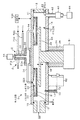
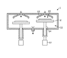
本発明の実施の形態に係る成膜装置は、図1(図2のI−I’線に沿った縦断面図)〜図3に示すように平面形状が概ね円形である扁平な真空容器1と、この真空容器1内に設けられ、当該の真空容器1の周方向に沿って配置された複数、例えば5つの載置台2と、これらの各載置台2に対向する位置に設けられ、当該載置台2との間に処理空間を形成するための上部材である天板部材22と、を備えている。載置台2は、この例では、基板の載置領域を有する下部材を成すものである。真空容器1は天板11及び底板14を側壁部12から分離できるように構成されており、天板11及び底板14は、封止部材例えばOリング13を介して側壁部12に、気密状態を維持しつつねじなどの不図示の留め具により固定されている。   A film forming apparatus according to an embodiment of the present invention includes a flat vacuum container 1 having a substantially circular planar shape as shown in FIG. 1 (longitudinal sectional view along line II ′ in FIG. 2) to FIG. And a plurality of, for example, five mounting tables 2 disposed in the vacuum container 1 along the circumferential direction of the vacuum container 1, and provided at positions facing these mounting tables 2, And a top plate member 22 that is an upper member for forming a processing space between the mounting table 2 and the mounting table 2. In this example, the mounting table 2 constitutes a lower member having a substrate mounting area. The vacuum vessel 1 is configured so that the top plate 11 and the bottom plate 14 can be separated from the side wall portion 12, and the top plate 11 and the bottom plate 14 are brought into an airtight state on the side wall portion 12 via a sealing member, for example, an O-ring 13. While being maintained, it is fixed by a fastener (not shown) such as a screw.

側壁部12から天板11、底板14を分離するときには、天板11を図示しない駆動機構により持ち上げ、また底板14を後述の昇降機構により降下させることができるようになっている。   When separating the top plate 11 and the bottom plate 14 from the side wall portion 12, the top plate 11 can be lifted by a drive mechanism (not shown), and the bottom plate 14 can be lowered by a lifting mechanism described later.

載置台2は、例えばアルミニウムやニッケルなどからなる円形状の板部材であり、当該載置台2の直径は、本成膜装置で処理される基板である例えば直径300mmのウエハWよりもひとまわり大きく形成されている。各載置台2の上面には凹部26が設けられていて、ウエハWを載置するための載置領域(載置面)となっている。また各載置台2には、載置面上のウエハWを加熱するための、例えばシート状の抵抗発熱体より構成される加熱手段を成すステージヒータ21が埋設されており、不図示の電源部より供給される電力によって載置台2上のウエハWを例えば300℃〜450℃程度に加熱することができる。なお必要に応じて載置台2内に図示しない静電チャックを設けて、載置台2上に載置されたウエハWを静電吸着して固定することができる。また図3には便宜上1個の載置台2だけにウエハWを描いてある。   The mounting table 2 is a circular plate member made of, for example, aluminum or nickel, and the diameter of the mounting table 2 is slightly larger than a wafer W having a diameter of, for example, 300 mm, which is a substrate processed by the film forming apparatus. Is formed. A recess 26 is provided on the upper surface of each mounting table 2, which serves as a mounting area (mounting surface) for mounting the wafer W. Each stage 2 is embedded with a stage heater 21 that constitutes a heating means composed of, for example, a sheet-like resistance heating element for heating the wafer W on the mounting surface. The wafer W on the mounting table 2 can be heated to, for example, about 300 ° C. to 450 ° C. by the supplied electric power. If necessary, an electrostatic chuck (not shown) may be provided in the mounting table 2 so that the wafer W mounted on the mounting table 2 can be electrostatically attracted and fixed. In FIG. 3, for convenience, the wafer W is drawn on only one mounting table 2.

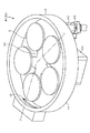
各載置台2は、底面側の中央部を支持腕23によって支持されており、これら支持腕23の基端側は、底板14の中央部を垂直方向に貫通する支柱24の頂部に接続されている。本例では例えば5本の支持腕23が、載置台2を支持する先端側を真空容器1の径方向に向けてほぼ水平に伸び出しており、隣り合う支持腕23同士は周方向にほぼ等角度の間隔を空けて放射状に配置されている。この結果、図2、図3に示すように、支持腕23の先端部に支持された載置台2についても支柱24の周囲に、真空容器1の周方向に沿って等間隔に配置された状態となり、各載置台2の中心は支柱24を中心とする円の周上に位置することとなる。   Each mounting table 2 is supported by a support arm 23 at the center on the bottom surface side, and the base end side of these support arms 23 is connected to the top of a column 24 that vertically penetrates the center of the bottom plate 14. Yes. In this example, for example, five support arms 23 extend substantially horizontally with the tip side supporting the mounting table 2 facing the radial direction of the vacuum vessel 1, and the adjacent support arms 23 are substantially equal in the circumferential direction. They are arranged radially at angular intervals. As a result, as shown in FIGS. 2 and 3, the mounting table 2 supported at the tip of the support arm 23 is also arranged around the support column 24 at equal intervals along the circumferential direction of the vacuum vessel 1. Thus, the center of each mounting table 2 is located on the circumference of a circle centered on the column 24.

底板14を貫通する支柱24の下端側は駆動部51と接続されており、支持腕23を介して当該支柱24に接続された全ての載置台2を同時に上下に昇降させることができる。即ち、本例においては支持腕23、支柱24、駆動部51は各載置台2の共通の昇降手段を構成している。また駆動部51は、支柱24を鉛直軸周りに例えば一回転させることができる回転手段としての役割も備えており、これにより支持腕23に支持された載置台2を当該鉛直軸周りに周方向に移動させることができる。また図1に示すスリーブ25は支柱24を収納して真空容器1の気密状態を維持する役割を果たし、磁気シール18は当該支柱24とスリーブ25で囲まれた空間内の雰囲気と、真空容器1内の雰囲気とを気密に区画する役割を果たす。   The lower end side of the column 24 penetrating the bottom plate 14 is connected to the drive unit 51, and all the mounting tables 2 connected to the column 24 can be moved up and down simultaneously via the support arm 23. That is, in this example, the support arm 23, the support column 24, and the drive unit 51 constitute a common lifting means for each mounting table 2. Further, the drive unit 51 also has a role as a rotating means that can rotate the support column 24 around the vertical axis, for example, so that the mounting table 2 supported by the support arm 23 is circumferentially moved around the vertical axis. Can be moved to. Further, the sleeve 25 shown in FIG. 1 serves to store the support column 24 and maintain the airtight state of the vacuum vessel 1, and the magnetic seal 18 is used to create an atmosphere in the space surrounded by the support column 24 and the sleeve 25 and the vacuum vessel 1. It plays the role of airtightly partitioning the atmosphere inside.

真空容器1の側壁部12には図2、図3に示すように外部の基板搬送手段である搬送アーム101と各載置台2との間でウエハWの受け渡しを行うための受け渡し口を成す搬送口15が形成されており、この搬送口15は図示しないゲートバルブにより開閉されるようになっている。各載置台2は、支柱24を回転させることにより真空容器1内を周方向に移動し、搬送口15に臨む位置にて順次停止してウエハWの受け渡しを行うことができる。当該受け渡し位置の下方側の底板14には、各載置台2に設けられた不図示の貫通孔を介して載置面から突没し、ウエハWを裏面側から持ち上げて搬送アーム101と各載置台2との間の受け渡しを行うための例えば3本の昇降ピン16が設けられている。昇降ピン16は、その底部を昇降板53に支持され、この昇降板53を駆動部52によって上下させることにより、昇降ピン16全体を昇降させることができる。ベローズ17は、昇降ピン16を覆って底板14の底面と昇降板53とに接続されており、真空容器1内の気密状態を維持する役割を果たす。   As shown in FIGS. 2 and 3, the side wall 12 of the vacuum vessel 1 has a transfer port for transferring the wafer W between the transfer arm 101 which is an external substrate transfer means and each mounting table 2. A port 15 is formed, and the transport port 15 is opened and closed by a gate valve (not shown). Each mounting table 2 can move in the circumferential direction in the vacuum vessel 1 by rotating the support column 24, and sequentially stop at a position facing the transfer port 15 to transfer the wafer W. The bottom plate 14 on the lower side of the delivery position projects and sinks from the mounting surface through a through hole (not shown) provided in each mounting table 2, and lifts the wafer W from the back surface side to transfer the transfer arm 101 and each mounting plate. For example, three elevating pins 16 for delivering to and from the mounting table 2 are provided. The raising / lowering pin 16 is supported by the raising / lowering plate 53 at the bottom, and the raising / lowering plate 53 can be moved up and down by the drive unit 52 to raise and lower the entire raising / lowering pin 16. The bellows 17 covers the lifting pins 16 and is connected to the bottom surface of the bottom plate 14 and the lifting plate 53, and plays a role of maintaining an airtight state in the vacuum vessel 1.

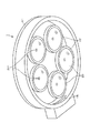
真空容器1の天板11の下面には、既述の載置台2と同様に、真空容器1の中心の周囲に周方向に並ぶように、載置台2と同数の例えば5つの天板部材22が固定されており、成膜を行う際には各天板部材22は夫々1つの載置台2に対向して処理空間20を形成し、5つの組(載置台2と天板部材22との組)を構成する。ここで既述のように載置台2は、支柱24を中心として周方向に移動可能に構成されていることから、これらの載置台2を予め定めた位置(以下、この位置を「処理位置」という)に停止させた場合に、天板部材22は各々対応する載置台2と対向することとなる。   On the lower surface of the top plate 11 of the vacuum vessel 1, for example, five top plate members 22 of the same number as the mounting table 2 so as to be arranged in the circumferential direction around the center of the vacuum vessel 1 like the mounting table 2 described above. When the film formation is performed, each top plate member 22 forms a processing space 20 so as to face one mounting table 2, and five sets (the mounting table 2 and the top plate member 22 are connected to each other). Group). Here, as described above, the mounting table 2 is configured to be movable in the circumferential direction around the support column 24. Therefore, the mounting table 2 is set at a predetermined position (hereinafter, this position is referred to as a "processing position"). In this case, the top plate member 22 is opposed to the corresponding mounting table 2.

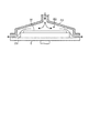
図4に示すように各天板部材22は、上面に平坦面を有する円柱体の下面を、周縁から中心部に向かうにつれて連続的に深くなるように窪ませて、上部から下に向かうにつれて末広がりの円錐形状を成す凹状の面(ラッパ形状の凹部)を形成した本体部分22aと、この本体部分22aの外周に、これを密着して囲むようにして設けられていると共に、その下端面が平坦面を成し、前記本体部分の周縁の高さと同じ高さ寸法に形成されたスリーブ22bとを備えている。これらの本体部分22aとスリーブ22bとは例えばアルミニウムなどから構成されている。前記凹部は、例えば載置台2上に載置されるウエハWの全体を覆うように当該ウエハWよりも一回り大きな径を有する円形状に開口しており、天板部材22の下端から載置台2の上面までの距離は「h」となっている。スリーブ22bの底面は、この天板部材22の下端と同じ高さ位置となっているため、載置台2を天板部材22に対向させると、天板部材22の下縁と載置台2との間には、周方向に幅「h」の隙間が形成される。   As shown in FIG. 4, each top plate member 22 has a bottom surface of a cylindrical body having a flat surface on the top surface that is continuously depressed from the peripheral edge toward the center, and is expanded toward the bottom from the top. And a main body portion 22a formed with a concave surface (a trumpet-shaped concave portion) having a conical shape, and an outer periphery of the main body portion 22a so as to closely surround it, and its lower end surface is a flat surface. And a sleeve 22b formed to have the same height as the peripheral edge of the main body portion. The main body portion 22a and the sleeve 22b are made of, for example, aluminum. The concave portion is opened in a circular shape having a diameter that is slightly larger than the wafer W so as to cover the entire wafer W placed on the placement table 2, for example, and is placed from the lower end of the top plate member 22. The distance to the top surface of 2 is “h”. Since the bottom surface of the sleeve 22 b is at the same height as the lower end of the top plate member 22, when the mounting table 2 is opposed to the top plate member 22, the lower edge of the top plate member 22 and the mounting table 2 are A gap having a width “h” is formed between them in the circumferential direction.

このように凹部を備えた天板部材22と円盤状の載置台2とを対向させて配置することにより、各組の載置台2と天板部材22との間には、例えば本例では円錐状の空間が形成される。本実施の形態に係る成膜装置では、これらの空間は複数種類の反応ガスを切り替えて拡散させ、ウエハW表面にて吸着、反応させて成膜を行う処理空間20となっている。そして処理空間20内に供給された各種ガスは、当該処理空間20の周方向に沿って載置台2と天板部材22との間に形成された前述の隙間を介して真空容器1内へと流出することになる。本実施の形態に係る成膜装置において当該隙間は、処理空間20内と、当該処理空間20の外部である真空容器1内の雰囲気(後述の排気空間10に相当する)とを連通するための排気用開口部に相当する。   Thus, by arranging the top plate member 22 having the concave portion and the disk-like mounting table 2 so as to face each other, for example, in this example, a cone is provided between the mounting table 2 and the top plate member 22. A shaped space is formed. In the film forming apparatus according to the present embodiment, these spaces serve as a processing space 20 in which film formation is performed by switching and diffusing a plurality of types of reactive gases and adsorbing and reacting on the surface of the wafer W. Various gases supplied into the processing space 20 enter the vacuum container 1 through the gap formed between the mounting table 2 and the top plate member 22 along the circumferential direction of the processing space 20. It will be leaked. In the film forming apparatus according to the present embodiment, the gap communicates the inside of the processing space 20 with the atmosphere in the vacuum vessel 1 that is outside the processing space 20 (corresponding to an exhaust space 10 described later). This corresponds to the exhaust opening.

各天板部材22の円錐状に形成された凹部の頂部にはガス供給口221が形成されており、このガス供給口221より処理空間20内に反応ガス及び当該反応ガスをパージするパージガスが供給される。   A gas supply port 221 is formed at the top of the conical recess of each top plate member 22, and a reaction gas and a purge gas for purging the reaction gas are supplied into the processing space 20 from the gas supply port 221. Is done.

天板11の中央部上には各処理空間20にガスを供給するためのマニホールド部3が設けられている。マニホールド部3は、ガス供給路32を形成する垂直な筒状の流路部材31aと、このガス供給路32の下流端が、その上面中央部に接続された大径の扁平な円筒部材31bとを備えている。そして、この円筒部材31bは、垂直なガス供給路32から導入されるガスを拡散して、5本のガス供給管34に供給するためのガス拡散室33を構成する。   On the central portion of the top plate 11, a manifold portion 3 for supplying gas to each processing space 20 is provided. The manifold section 3 includes a vertical cylindrical flow path member 31a that forms a gas supply path 32, and a large-diameter flat cylindrical member 31b in which the downstream end of the gas supply path 32 is connected to the center of the upper surface thereof. It has. The cylindrical member 31 b constitutes a gas diffusion chamber 33 for diffusing the gas introduced from the vertical gas supply path 32 and supplying the gas to the five gas supply pipes 34.

ガス供給管34は各々同様に構成されており、大径の円筒部材31bの側壁から周方向に略等角度の間隔をおいて放射状に伸び出している。そして各ガス供給管34の下流端は前記ガス供給口221に接続されている。   The gas supply pipes 34 are configured in the same manner, and extend radially from the side wall of the large-diameter cylindrical member 31b at substantially equal angular intervals in the circumferential direction. The downstream end of each gas supply pipe 34 is connected to the gas supply port 221.

流路部材31aには、気化して成膜を行うための原料ガスを生じる例えばBTBASなどの第1の反応ガスの原料となる液体原料を横方向からガス供給路32に供給するインジェクタ4が設けられている。原料ガスについては後に詳述する。このインジェクタ4には液体原料の供給配管713が接続されており、供給配管713の上流側は後述の制御部100によりその動作が制御されるポンプ711を介して、前記BTBASなどの液体原料が貯留された原料ガス供給源71に接続されている。この原料ガス供給源71としては例えばインジェクタ4の上方に配置され、原料ガス供給源71からインジェクタ4までの供給路が長くなることを抑えている。このような配置によって、液体原料の劣化即ち揮発や分解による液体原料中のBTBASの濃度が低下することを抑えて、装置の運転のコストの低下を図っている。このように液体原料の劣化を抑えるため、原料ガス供給源71からインジェクタ4間での供給配管の長さは例えば2m以下に構成されている。   The flow path member 31a is provided with an injector 4 for supplying a liquid source, which is a source of a first reaction gas such as BTBAS, which generates a source gas for vapor deposition to form a film, from the lateral direction to the gas supply path 32. It has been. The source gas will be described in detail later. A liquid source supply pipe 713 is connected to the injector 4, and the upstream side of the supply pipe 713 stores a liquid source such as BTBAS via a pump 711 whose operation is controlled by a control unit 100 described later. The source gas supply source 71 is connected. The source gas supply source 71 is disposed, for example, above the injector 4 to suppress an increase in the supply path from the source gas supply source 71 to the injector 4. With such an arrangement, the deterioration of the liquid material, that is, the decrease in the concentration of BTBAS in the liquid material due to volatilization or decomposition is suppressed, thereby reducing the operating cost of the apparatus. In this way, in order to suppress the deterioration of the liquid material, the length of the supply pipe between the material gas supply source 71 and the injector 4 is configured to be 2 m or less, for example.

このインジェクタ4としては従来公知のものが用いられ、その構成の要部を縦断面図である図6を参照しながら以下に簡単に説明する。インジェクタ4は本体部41を備え、本体部41には前記液体原料が供給される供給通路42が、その長さ方向に設けられている。図中の矢印は液体原料の流れを示しており、液体原料は前記ポンプ711により加圧された状態でこの供給通路42を流通する。   As the injector 4, a conventionally known one is used, and the main part of the configuration will be briefly described below with reference to FIG. 6 which is a longitudinal sectional view. The injector 4 includes a main body 41, and a supply passage 42 through which the liquid raw material is supplied is provided in the main body 41 in the length direction thereof. The arrows in the figure indicate the flow of the liquid raw material, and the liquid raw material flows through the supply passage 42 while being pressurized by the pump 711.

前記供給通路42の上流側には液体成膜原料を浄化するためのフィルタ44Aが設けられている。また供給通路42の下流側は縮径されて縮径部42Aを成し、その縮径部42Aの下流端にはニードルバルブ44によって開閉される吐出口45が形成されている。ニードルバルブ44はプランジャ46を介してリターンスプリング47により下流側へ向かって付勢されており、それによって前記縮径部42Aに当接し、吐出口45が塞がれている。また、プランジャ46を囲むように設けられたソレノイド48は電流供給部49に接続されており、電流が供給されることで電磁石として機能する。前記電流供給部49は、制御部100からの制御信号を受けて、ソレノイド48への電流の給断を制御する。   A filter 44 </ b> A for purifying the liquid film forming material is provided on the upstream side of the supply passage 42. The downstream side of the supply passage 42 is reduced in diameter to form a reduced diameter portion 42A, and a discharge port 45 that is opened and closed by a needle valve 44 is formed at the downstream end of the reduced diameter portion 42A. The needle valve 44 is urged toward the downstream side by a return spring 47 via a plunger 46, thereby contacting the reduced diameter portion 42 </ b> A and closing the discharge port 45. A solenoid 48 provided so as to surround the plunger 46 is connected to a current supply unit 49 and functions as an electromagnet when supplied with a current. The current supply unit 49 receives a control signal from the control unit 100 and controls supply / disconnection of the current to the solenoid 48.

ソレノイド48に電流が供給されてその周囲に磁界が形成されると、プランジャ46が供給通路42の上流側へと引かれ、それと同時にニードルバルブ44が上流側に引かれて吐出口45が開放され、供給通路42に加圧された状態で貯留されていた液体原料が当該吐出口45からガス供給路32に吐出される。図中大きな点線の丸で囲った部分にはこのように吐出口45が開放され、この吐出口45から液体原料がガス供給路32に吐出されるときの状態を拡大して示している。   When a current is supplied to the solenoid 48 and a magnetic field is formed around it, the plunger 46 is pulled upstream of the supply passage 42 and at the same time, the needle valve 44 is pulled upstream to open the discharge port 45. The liquid raw material stored in a pressurized state in the supply passage 42 is discharged from the discharge port 45 to the gas supply passage 32. A portion surrounded by a large dotted circle in the figure is such that the discharge port 45 is thus opened, and the state when the liquid material is discharged from the discharge port 45 to the gas supply path 32 is shown in an enlarged manner.

このようにインジェクタ4による液体原料の吐出が行われるときにガス供給路32は減圧されているので、液体原料は減圧沸騰してガスとなり、そのガスが下流へ流通する。ソレノイド48による磁界の形成が停止すると、リターンスプリング47によりプランジャ46が下流側へと押し戻され、ニードルバルブ44により吐出口45が塞がれる。ポンプ711の圧力と吐出口45の開口時間とにより、ガス供給路32で生成する第1の反応ガスの量が制御される。なお、このようにインジェクタ4より液体原料を減圧されたガス供給路32に供給して気化させる他に、供給配管713に気化器を設けて、当該気化器により液体原料を通流空間に供給する前に予め気化させて反応ガスを生成させ、その反応ガスを供給路32に供給してもよい。   Since the gas supply path 32 is decompressed when the liquid material is discharged by the injector 4 as described above, the liquid material is boiled under reduced pressure to become a gas, and the gas flows downstream. When the formation of the magnetic field by the solenoid 48 is stopped, the plunger 46 is pushed back downstream by the return spring 47 and the discharge port 45 is closed by the needle valve 44. The amount of the first reaction gas generated in the gas supply path 32 is controlled by the pressure of the pump 711 and the opening time of the discharge port 45. In addition to supplying the liquid raw material from the injector 4 to the decompressed gas supply path 32 for vaporization, a vaporizer is provided in the supply pipe 713 and the liquid raw material is supplied to the flow space by the vaporizer. It may be vaporized in advance to generate a reaction gas, and the reaction gas may be supplied to the supply path 32.

マニホールド部3には、液体原料を供給する供給配管713の他に図7に示すように各種のガスをガス供給路32へ供給するためのガス供給配管723、733が上下に接続されており、これらの配管723、733は上流側で夫々各種のガス供給源72、73と夫々接続されている。この例ではガス供給配管723,733はインジェクタ4による液体原料の供給方向とは異なる方向から各ガスをガス供給路32に供給できるようにマニホールド部3に接続されている。
本実施の形態に係る成膜装置は、金属元素、例えば周期表の第3周期の元素であるAl、Siなど、周期表の第4周期の元素であるTi、Cr、Mn、Fe、Co、Ni、Cu、Zn、Geなど、周期表の第5周期の元素であるZr、Mo、Ru、Rh、Pd、Agなど、周期表の第6周期の元素であるBa、Hf、Ta、W、Re、lr、Ptなどの元素を含む薄膜を成膜することが可能であり、ウエハW表面に吸着させる金属原料としてはこれらの金属元素の有機金属化合物や無機金属化合物などを反応ガス(以下、原料ガスという)として用いる場合が挙げられる。金属原料の具体例としては、上述のBTBASの他に、例えばDCS[ジクロロシラン]、HCD[ヘキサジクロロシラン]、TMA[トリメチルアルミニウム]、3DMAS[トリスジメチルアミノシラン]などを挙げることができる。
In addition to the supply pipe 713 for supplying the liquid raw material, the manifold section 3 is connected with gas supply pipes 723 and 733 for supplying various gases to the gas supply path 32 as shown in FIG. These pipes 723 and 733 are respectively connected to various gas supply sources 72 and 73 on the upstream side. In this example, the gas supply pipes 723 and 733 are connected to the manifold portion 3 so that each gas can be supplied to the gas supply path 32 from a direction different from the direction in which the liquid raw material is supplied by the injector 4.
The film formation apparatus according to the present embodiment includes metal elements, for example, Ti, Cr, Mn, Fe, Co, which are elements of the fourth period of the periodic table, such as Al and Si, which are elements of the third period of the periodic table. Ba, Hf, Ta, W, which are elements of the sixth period of the periodic table, such as Zr, Mo, Ru, Rh, Pd, Ag, which are elements of the fifth period of the periodic table, such as Ni, Cu, Zn, Ge, etc. It is possible to form a thin film containing elements such as Re, lr, and Pt, and as a metal raw material to be adsorbed on the surface of the wafer W, an organic metal compound or an inorganic metal compound of these metal elements is used as a reactive gas (hereinafter referred to as “reactive gas”). As a raw material gas). Specific examples of the metal raw material include, in addition to the above-described BTBAS, DCS [dichlorosilane], HCD [hexadichlorosilane], TMA [trimethylaluminum], 3DMAS [trisdimethylaminosilane], and the like.

またウエハW表面に吸着した原料ガスを反応させて、所望の膜を得る反応には、例えばO、O、HOなどを利用した酸化反応、H、HCOOH、CHCOOHなどの有機酸、CHOH、COHなどのアルコール類などを利用した還元反応、CH、C、C、Cなどを利用した炭化反応、NH、NHNH、Nなどを利用した窒化反応などの各種反応を利用することができる。本実施の形態では背景技術にて例示したBTBASガスを原料ガスとして、酸素ガスを用いて酸化反応によりSiO膜を成膜する例について説明する。 In addition, for the reaction to obtain a desired film by reacting the raw material gas adsorbed on the surface of the wafer W, for example, an oxidation reaction using O 2 , O 3 , H 2 O, etc., H 2 , HCOOH, CH 3 COOH, etc. Reduction reaction using organic acids, alcohols such as CH 3 OH, C 2 H 5 OH, etc., carbonization reaction using CH 4 , C 2 H 6 , C 2 H 4 , C 2 H 2 , NH 3 , Various reactions such as a nitriding reaction using NH 2 NH 2 , N 2 or the like can be used. In the present embodiment, an example will be described in which a BTBAS gas exemplified in the background art is used as a source gas and an SiO 2 film is formed by an oxidation reaction using oxygen gas.

酸素ガス供給用の配管723は酸素ガス供給源72と接続され、またパージガス供給配管733はパージガス供給源73と接続され、夫々第2の反応ガスである酸素ガス及び、パージガスであるアルゴンガスを既述のガス供給路32へと供給することができる。ここでこれら酸素ガスやアルゴンガスをガス供給路32へと供給する供給配管723、733には、例えばダイヤフラム式の圧力調整弁721、731と、例えばディスク型のプランジャを採用した電磁弁からなる開閉弁722、732とが介設されており、一定圧力の各種ガスを大流量、且つ高い応答速度で供給することができるようになっている。   The oxygen gas supply pipe 723 is connected to the oxygen gas supply source 72, and the purge gas supply pipe 733 is connected to the purge gas supply source 73. The oxygen gas that is the second reaction gas and the argon gas that is the purge gas are already supplied. The gas can be supplied to the gas supply path 32 described above. Here, the supply pipes 723 and 733 for supplying these oxygen gas and argon gas to the gas supply path 32 are opened and closed including, for example, diaphragm-type pressure regulating valves 721 and 731 and electromagnetic valves employing, for example, disk-type plungers. Valves 722 and 732 are interposed so that various gases at a constant pressure can be supplied at a large flow rate and at a high response speed.

これら各ガス供給源71〜73に接続されたポンプ711、圧力調整弁721、731及び開閉弁722、732は、成膜装置のガス供給制御部7を構成しており、後述する制御部100からの指示に基づいて各種ガスの供給タイミングや等を制御することができる。
また本例では、以上に説明した各構成要素のうち、原料ガス供給源71、ポンプ711、原料ガス供給配管713、インジェクタ4、マニホールド部3及びガス供給管34は、第1の反応ガス供給部に相当し、酸素ガス供給源72、圧力調整弁721、開閉弁722、酸素ガス供給配管723、マニホールド部3及びガス供給管34は、第2の反応ガス供給部に相当し、またパージガス供給源73、圧力調整弁731、開閉弁732、パージガス供給配管733、マニホールド部3及びガス供給管34はパージガス供給部に相当している。
A pump 711, pressure regulating valves 721 and 731, and on-off valves 722 and 732 connected to these gas supply sources 71 to 73 constitute a gas supply control unit 7 of the film forming apparatus. The supply timing of various gases and the like can be controlled based on the instruction.
Also, in this example, among the components described above, the source gas supply source 71, the pump 711, the source gas supply pipe 713, the injector 4, the manifold section 3, and the gas supply pipe 34 are the first reactive gas supply section. The oxygen gas supply source 72, the pressure adjustment valve 721, the on-off valve 722, the oxygen gas supply pipe 723, the manifold part 3 and the gas supply pipe 34 correspond to the second reaction gas supply part, and the purge gas supply source 73, the pressure regulating valve 731, the on-off valve 732, the purge gas supply pipe 733, the manifold section 3, and the gas supply pipe 34 correspond to the purge gas supply section.

また、流路部材31aの上側には処理空間20内にプラズマガスを供給するためのリモートプラズマ供給部54が設けられている。装置のメンテナンスを行うにあたり、後述のように排気を行いながらNF3ガスを処理空間20に供給したときに、このリモートプラズマ供給部54によりそのNF3ガスをプラズマ化させて、プラズマを生成する。そして、このプラズマにより処理空間内20の付着物は処理空間20の壁面から除去され、処理空間20内に形成される排気流に乗って処理空間20から除去される。ところでリモートプラズマ供給部54の代わりにインジェクタ4を流路部材31aの上側に設けて、流路部材31aのガス供給路32の形成方向に沿ってインジェクタ4から液体原料を供給してもよい。 A remote plasma supply unit 54 for supplying plasma gas into the processing space 20 is provided above the flow path member 31a. In performing the maintenance of the apparatus, when the NF 3 gas is supplied to the processing space 20 while exhausting as will be described later, the remote plasma supply unit 54 converts the NF 3 gas into plasma to generate plasma. Then, the deposit in the processing space 20 is removed from the wall surface of the processing space 20 by this plasma, and is removed from the processing space 20 by riding on the exhaust flow formed in the processing space 20. Incidentally, instead of the remote plasma supply unit 54, the injector 4 may be provided on the upper side of the flow path member 31a, and the liquid raw material may be supplied from the injector 4 along the direction in which the gas supply path 32 of the flow path member 31a is formed.

真空容器1の説明に戻ると、図1、図3に示すように例えば底板14には、支柱24を挟んで搬送口15とは反対側の位置にて、各反応ガス及びパージガスを排気するための共通の排気口61が設けられている。この排気口61は排気管62と接続されており、当該排気管62は、真空容器1内の圧力調整を行う圧力調整手段63を介して真空排気手段を成す真空ポンプ64に接続されている。ここで真空容器1内には、既述のように成膜が行われる処理空間20を構成する5組の載置台2、天板部材22が配置されており、これらの処理空間20から流出した各種ガスはこの真空容器1内を通って共通の排気口61へと排気されることから、当該真空容器1は反応ガスの排気空間10を構成していることになる。即ち本実施の形態に係る成膜装置では、共通の排気空間10内に複数の処理空間20が配置された構造となっているといえる。   Returning to the description of the vacuum vessel 1, as shown in FIGS. 1 and 3, for example, the bottom plate 14 is used to exhaust each reaction gas and purge gas at a position opposite to the transfer port 15 with the support 24 interposed therebetween. The common exhaust port 61 is provided. The exhaust port 61 is connected to an exhaust pipe 62, and the exhaust pipe 62 is connected to a vacuum pump 64 that constitutes a vacuum exhaust means via a pressure adjusting means 63 that adjusts the pressure in the vacuum vessel 1. Here, in the vacuum vessel 1, as described above, the five sets of mounting tables 2 and the top plate member 22 that constitute the processing space 20 in which film formation is performed are arranged, and flowed out of these processing spaces 20. Various gases are exhausted to the common exhaust port 61 through the inside of the vacuum container 1, so that the vacuum container 1 constitutes an exhaust space 10 for the reaction gas. That is, it can be said that the film forming apparatus according to the present embodiment has a structure in which a plurality of processing spaces 20 are arranged in a common exhaust space 10.

以上に説明した構造を備える成膜装置は、既述のガス供給源71〜73からのガス供給動作、載置台2の回転及び昇降動作や真空ポンプ64による真空容器1の排気動作、各ステージヒータ21による加熱動作などを制御する制御部100を備えている。制御部100は例えば図示しないCPUと記憶部とを備えたコンピュータからなり、この記憶部には当該成膜装置によってウエハWへの成膜を行うのに必要な制御、例えばガス供給源71〜73からの各種ガス供給の給断タイミングや供給量調整に係る制御、真空容器1内の真空度を調節する制御、載置台2の昇降、回転動作制御や各ステージヒータ21の温度制御などについてのステップ(命令)群が組まれたプログラムが記録されている。このプログラムは、例えばハードディスク、コンパクトディスク、マグネットオプティカルディスク、メモリカードなどの記憶媒体に格納され、そこからコンピュータにインストールされる。   The film forming apparatus having the above-described structure includes a gas supply operation from the gas supply sources 71 to 73 described above, a rotation and elevation operation of the mounting table 2, an exhaust operation of the vacuum vessel 1 by the vacuum pump 64, and each stage heater. The control part 100 which controls the heating operation by 21 etc. is provided. The control unit 100 includes, for example, a computer including a CPU and a storage unit (not shown). The storage unit includes controls necessary for film formation on the wafer W by the film formation apparatus, for example, gas supply sources 71 to 73. Steps relating to control of supply / disconnection of various gases from the gas, control of supply amount adjustment, control of adjusting the degree of vacuum in the vacuum vessel 1, raising / lowering of the mounting table 2, rotation operation control, temperature control of each stage heater 21, etc. A program in which (instruction) groups are assembled is recorded. This program is stored in a storage medium such as a hard disk, a compact disk, a magnetic optical disk, or a memory card, and is installed in the computer therefrom.

以下、本実施の形態に係る成膜装置の動作について説明する。先ず載置台2をウエハWの受け渡し位置に下降させた状態で図8に示すように、図示しないゲートバルブにより搬送口15を開き、外部の搬送アーム101を搬送口15より進入させて真空容器1内にウエハWを搬入する。このとき、真空容器1内の搬送口15に対向する位置(ウエハWの受け渡し位置)には、支柱24を回転させることにより、次にウエハWを載置する載置台2が待機している。そして不図示の貫通孔を介して昇降ピン16を載置台2から突出させ搬送アーム101から昇降ピン16にウエハWを受け渡し、搬送アーム101を真空容器1外に退避させてから昇降ピン16を載置台2の下方へと没入させることにより、載置面である凹部26内にウエハWが載置される。そしてウエハWは不図示の静電チャックにより吸着固定される。   Hereinafter, the operation of the film forming apparatus according to the present embodiment will be described. First, as shown in FIG. 8 in a state where the mounting table 2 is lowered to the delivery position of the wafer W, the transfer port 15 is opened by a gate valve (not shown), and the external transfer arm 101 is advanced from the transfer port 15 to enter the vacuum container 1. The wafer W is loaded into the inside. At this time, at the position facing the transfer port 15 in the vacuum container 1 (the delivery position of the wafer W), the mounting table 2 on which the wafer W is placed next is waiting by rotating the support 24. Then, the lifting pins 16 protrude from the mounting table 2 through a through hole (not shown), the wafer W is transferred from the transfer arm 101 to the lifting pins 16, the transfer arm 101 is retracted out of the vacuum container 1, and then the lifting pins 16 are mounted. The wafer W is placed in the recess 26 which is a placement surface by being immersed below the placement table 2. The wafer W is attracted and fixed by an electrostatic chuck (not shown).

このようにして5つの載置台2に順次ウエハWを載置する動作を繰り返してウエハWの搬入を完了したら、各載置台2を処理位置まで移動させて天板部材22に対向させた状態で停止する。このとき載置台2はステージヒータ21により予め例えば300℃〜450℃に加熱されており、ウエハWはこの載置台2に載置されることで加熱される。そして、ウエハWの搬入位置まで下降していた載置台2を上昇させ、例えば当該成膜のレシピにて選択された高さ位置にて停止させる。   In this way, after the operation of sequentially placing the wafers W on the five mounting tables 2 is repeated and the loading of the wafers W is completed, each mounting table 2 is moved to the processing position and opposed to the top plate member 22. Stop. At this time, the mounting table 2 is preheated to, for example, 300 ° C. to 450 ° C. by the stage heater 21, and the wafer W is heated by being mounted on the mounting table 2. Then, the mounting table 2 that has been lowered to the loading position of the wafer W is raised and stopped, for example, at a height position selected in the deposition recipe.

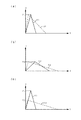
ここで本実施の形態に係る成膜装置は、載置台2を停止させる高さ位置を調節することにより、載置台2と天板部材22との間に形成される隙間の幅(隙間の大きさ)を例えば「h=1mm〜6mm」の範囲で変化させることができる。例えば図9(a)には、前記隙間の幅を「h=4mm」とした場合を示し、図9(b)には前記隙間の幅を「h=2mm」とした場合を示している。   Here, the film forming apparatus according to the present embodiment adjusts the height position at which the mounting table 2 is stopped, thereby adjusting the width of the gap formed between the mounting table 2 and the top plate member 22 (the size of the gap). For example, in the range of “h = 1 mm to 6 mm”. For example, FIG. 9A shows a case where the width of the gap is “h = 4 mm”, and FIG. 9B shows a case where the width of the gap is “h = 2 mm”.

このようにして各載置台2を天板部材22に対向させ、隙間の幅を調節したら、搬送口15を閉じて真空容器1内を気密な状態とした後、真空ポンプ64を稼動させて真空容器1内を引き切りの状態とする。そして真空容器1内が所定の圧力、例えば13.3Pa(0.1Torr)まで真空排気され、さらにウエハWの温度を既述の温度範囲の例えば350℃まで昇温したら成膜を開始する。   After each mounting table 2 is made to face the top plate member 22 and the width of the gap is adjusted in this way, the transfer port 15 is closed to make the inside of the vacuum vessel 1 airtight, and then the vacuum pump 64 is operated to perform vacuum. The inside of the container 1 is set to a draw state. Then, the inside of the vacuum chamber 1 is evacuated to a predetermined pressure, for example, 13.3 Pa (0.1 Torr), and the film formation is started when the temperature of the wafer W is raised to, for example, 350 ° C. of the above-described temperature range.

本実施の形態に係る成膜装置を用いたいわゆるALDプロセスにおいては、成膜は例えば図10(a)、図10(b)に示すガス供給シーケンスに基づいて実行さる。図10(a)、図10(b)は夫々載置台2と天板部材22との間の隙間の幅が「h=4mm」(図9(a)に対応)の場合と、「h=2mm」(図9(b)に対応)の場合とにおけるガス供給シーケンスを示した模式図である。これらの図の横軸は時間を示し、縦軸は処理空間20内の圧力を示している。   In a so-called ALD process using the film forming apparatus according to the present embodiment, film formation is performed based on, for example, a gas supply sequence shown in FIGS. 10 (a) and 10 (b). 10A and 10B show the case where the width of the gap between the mounting table 2 and the top plate member 22 is “h = 4 mm” (corresponding to FIG. 9A), and “h = It is the schematic diagram which showed the gas supply sequence in the case of 2 mm "(corresponding | compatible to FIG.9 (b)). In these drawings, the horizontal axis indicates time, and the vertical axis indicates the pressure in the processing space 20.

例えば図10(a)(h=4mm)の場合を見てみると、まず原料(ガス第1の反応ガス:BTBAS)を各処理空間20内に供給し、載置台2上のウエハWに吸着させる工程を実行する(原料ガス吸着工程:以下、「吸着工程」と略記する。図10(a)中に「a工程」と記載してある)。このとき原料ガス供給源71に貯留されているBTBASの液体原料は、例えばインジェクタ4の吐出口45を例えば1ms間だけ開くことにより、減圧されたガス供給路32に吐出されて、減圧沸騰し、第1の反応ガスであるBTBASガスとなって図11に矢印で示すように下流側のガス拡散室33に供給される。そして、BTBASガスはガス拡散室33を拡散して、下流側へと向かう。   For example, looking at the case of FIG. 10A (h = 4 mm), first, the raw material (gas first reaction gas: BTBAS) is supplied into each processing space 20 and is adsorbed to the wafer W on the mounting table 2. (Source gas adsorption step: hereinafter abbreviated as “adsorption step”. In FIG. 10A, “a step” is described). At this time, the BTBAS liquid source stored in the source gas supply source 71 is discharged to the reduced pressure gas supply path 32 by, for example, opening the discharge port 45 of the injector 4 for 1 ms, for example, and boiled under reduced pressure. The BTBAS gas, which is the first reaction gas, is supplied to the downstream gas diffusion chamber 33 as shown by the arrow in FIG. The BTBAS gas diffuses in the gas diffusion chamber 33 and travels downstream.

そして、気化された原料ガスは、ガス供給口221を介して各処理空間20へ導入され、これにより図10(a)中のa工程に示すように処理空間20内の圧力が例えば133.32Pa(1Torr)まで上昇する。一方、既述のように各処理空間20は排気空間10内に配置されていることから、処理空間20内に供給された原料ガスは処理空間20内よりも圧力の低い排気空間10に向けて流れ、載置台2と天板部材22との間の隙間を介して排気空間10へと流出する。   Then, the vaporized source gas is introduced into each processing space 20 via the gas supply port 221, and thereby the pressure in the processing space 20 is, for example, 133.32 Pa as shown in step a in FIG. Rise to (1 Torr). On the other hand, since each processing space 20 is disposed in the exhaust space 10 as described above, the source gas supplied into the processing space 20 is directed toward the exhaust space 10 having a lower pressure than that in the processing space 20. The air flows out into the exhaust space 10 through the gap between the mounting table 2 and the top plate member 22.

この結果、図12に示すように原料ガスは、円錐状の処理空間20の頂部、即ちウエハW中央部の上方に設けられたガス供給口221より処理空間20内に供給され、当該処理空間20内を広がりながらウエハWの表面を前記隙間へ向けて径方向に流れ、この間、当該ウエハWの表面に吸着してBTBASの分子層を形成する。そして間欠的に供給された原料ガスが処理空間20内から排気空間10へ向けて排気されるにつれて、図10(a)のa工程に示したように処理空間20内の圧力は低下していく。   As a result, as shown in FIG. 12, the source gas is supplied into the processing space 20 from the top of the conical processing space 20, that is, the gas supply port 221 provided above the center of the wafer W. The surface of the wafer W flows in the radial direction toward the gap while expanding inside, and during this time, it is adsorbed on the surface of the wafer W to form a BTBAS molecular layer. As the source gas supplied intermittently is exhausted from the processing space 20 toward the exhaust space 10, the pressure in the processing space 20 decreases as shown in step a of FIG. .

次いで、例えば処理空間20の圧力が原料ガス導入前とほぼ同じ圧力となるタイミング、例えば原料ガスを供給してから予め決めた時間が経過したタイミングにて、処理空間20内に滞留している原料ガスをパージする工程に移る(図10(a)のb工程)。ここで例えばパージガス供給源73の下流に設けられた圧力調整弁731は出口側の二次圧を0.1MPaと一定にするように調整されており、開閉弁732は入口側にこの圧力がかかった状態で「閉」となっている。そしてb工程の開始タイミングにて例えば100ms間だけ開閉弁732を「開」とすると、当該開閉弁732前後の圧力バランス、及び開閉弁732の開放時間に応じた量のパージガスがマニホールド部3を介して処理空間20に供給される。 Next, for example, the raw material staying in the processing space 20 at a timing at which the pressure in the processing space 20 becomes substantially the same as that before the introduction of the raw material gas, for example, at a timing when a predetermined time has elapsed since the supply of the raw material gas. Turning to purging the gas (b 1 process of FIG. 10 (a)). Here, for example, the pressure adjusting valve 731 provided downstream of the purge gas supply source 73 is adjusted so that the secondary pressure on the outlet side is kept constant at 0.1 MPa, and the on-off valve 732 applies this pressure on the inlet side. In the closed state. And When b 1 "open" at the start timing of the on-off valve 732 only between eg 100ms step, the pressure balance in front and rear the on-off valve 732, and a purge gas manifold portion 3 in an amount corresponding to the opening time of the switch valve 732 To the processing space 20.

この結果、原料ガスの場合と同様に図12に示すように、パージガスは円錐状の各処理空間20を広がりながらウエハWの表面を流れ、処理空間20内に滞留している原料ガスと共に載置台2と天板部材22との間の隙間を介して排気空間10へ向けて排気される。この際、処理空間20内の圧力は図10(a)のb工程に示すように、開閉弁732の開閉動作によって供給されたパージガスの量に応じて例えば666.7Pa(5Torr)まで上昇し、このパージガスが排気空間10へ向けて排気されるにつれて低下する。 As a result, as in the case of the source gas, as shown in FIG. 12, the purge gas flows on the surface of the wafer W while spreading in each conical processing space 20, and together with the source gas remaining in the processing space 20, the mounting table 2 and the top plate member 22 are exhausted toward the exhaust space 10 through a gap. At this time, the pressure in the processing space 20, as shown in b 1 step of FIG. 10 (a), elevated example to 666.7Pa (5Torr) depending on the amount of purge gas supplied by the opening and closing operation of the opening and closing valve 732 The purge gas decreases as it is exhausted toward the exhaust space 10.

こうして処理空間20内に滞留している原料ガスがパージガスと共に排気されたタイミング、例えばパージガスを供給してから予め決めた時間経過したタイミングにて、ウエハWに吸着した原料ガスを酸化するために、処理空間20内に第2の反応ガスである酸素ガスを供給する工程を実行する(以下、「酸化工程」という。図10(a)のc工程)。例えば酸素ガス供給源72の下流に設けられた圧力調整弁721は、パージガスの圧力調整弁731と同様に出口側の二次圧を0.1MPaにするように調整されており、開閉弁722は入口側にこの圧力がかかった状態で「閉」となっている。そしてc工程の開始タイミングにて例えば100ms間だけ開閉弁722を「開」とすると、当該開閉弁722前後の圧力バランス、及びこれを開とした時間に応じた量の酸素ガスがマニホールド部3を介して処理空間20に供給される。   In order to oxidize the raw material gas adsorbed on the wafer W at the timing when the raw material gas staying in the processing space 20 is exhausted together with the purge gas, for example, at a timing when a predetermined time has elapsed after supplying the purge gas, A step of supplying oxygen gas as the second reaction gas into the processing space 20 is executed (hereinafter referred to as “oxidation step”, step c in FIG. 10A). For example, the pressure adjustment valve 721 provided downstream of the oxygen gas supply source 72 is adjusted so that the secondary pressure on the outlet side is 0.1 MPa, similarly to the pressure adjustment valve 731 for the purge gas. It is “closed” when this pressure is applied to the inlet side. When the opening / closing valve 722 is opened for 100 ms, for example, at the start timing of step c, oxygen gas in an amount corresponding to the pressure balance before and after the opening / closing valve 722 and the time for opening the opening / closing valve 722 opens the manifold portion 3. To the processing space 20.

そしてこれまでのガス供給の場合と同様、図12に示すように酸素ガスは円錐形の処理空間20を広がりながらウエハWの表面を流れ、ウエハW表面に吸着している原料ガスを酸化することによりSiOの分子層が形成される。この際、処理空間20内の圧力は図10(a)のc工程に示すように、開閉弁722の開閉動作によって供給された酸素ガスの量に応じて666.7Pa(5Torr)まで上昇し、このパージガスが排気空間10へ向けて排気されるにつれて低下する。 As in the case of the gas supply so far, as shown in FIG. 12, the oxygen gas flows on the surface of the wafer W while expanding the conical processing space 20, and oxidizes the source gas adsorbed on the surface of the wafer W. As a result, a molecular layer of SiO 2 is formed. At this time, the pressure in the processing space 20 rises to 666.7 Pa (5 Torr) according to the amount of oxygen gas supplied by the opening / closing operation of the opening / closing valve 722, as shown in step c of FIG. The purge gas decreases as it is exhausted toward the exhaust space 10.

引き続き、例えば処理空間20の圧力が酸素ガス導入前とほぼ同じ圧力となるタイミング、例えば酸素ガスを供給してから予め決めた時間が経過したタイミングにて、既述のb工程と同じ要領にてパージガスを供給し、処理空間20内に滞留している酸素ガスをパージする(b工程)。そして図10(a)に示すように、以上に説明した4つの工程を1サイクルとすると、当該サイクルを予め決められた回数、例えば125回繰り返してSiOの分子層を多層化し、たとえば10nmの膜厚を有する膜の成膜を完了する。なお、図10(a)及び後述の図10(b)は、説明の便宜上、各工程における処理空間20内の圧力パターンを模式的に表したものであり、当該処理空間20内の厳密な圧力を示しているものではない。 Subsequently, for example, the timing at which the pressure of the processing space 20 is substantially the same pressure as before oxygen gas introduction, for example, oxygen gas at predetermined time has elapsed timing from the supply, in the same way as already described b 1 step Te purge gas supply to purge oxygen gas staying in the processing space 20 (b 2 steps). Then, as shown in FIG. 10 (a), when the above-described four steps are defined as one cycle, the cycle is repeated a predetermined number of times, for example, 125 times, and the molecular layer of SiO 2 is multilayered, for example, 10 nm. The film formation having a film thickness is completed. Note that FIG. 10A and FIG. 10B described later schematically show the pressure pattern in the processing space 20 in each step for convenience of explanation, and the strict pressure in the processing space 20 is shown. It does not indicate.

成膜を終えたらガスの供給を停止し、ウエハWの載置された載置台2を搬送口15まで降下させ、真空容器1内の圧力を真空排気前の状態に戻した後、搬入時とは逆の経路で外部の搬送アーム101によりウエハWを搬出し、一連の成膜動作を終える。   When the film formation is completed, the gas supply is stopped, the mounting table 2 on which the wafer W is mounted is lowered to the transfer port 15, the pressure in the vacuum vessel 1 is returned to the state before the vacuum exhaust, In the reverse path, the wafer W is unloaded by the external transfer arm 101, and a series of film forming operations is completed.

以上に説明した動作に基づき成膜を行う本実施の形態に係る成膜装置は、5つの処理空間20に共通のマニホールド部3から反応ガスの供給が行われ、また共通の排気空間10へ向けて各処理空間20からの反応ガスの排気が行われることになる。このため、5つの処理空間20の間で供給される反応ガスの量に若干の差を生じる場合も考えられる。しかしながら、本成膜装置はウエハW表面への反応ガスの吸着を利用するALDプロセスを採用していることから、各処理空間20への反応ガス供給量に多少の偏りなどがあったとしても、分子層を形成可能な十分な量の反応ガスをウエハW表面に供給することが可能であれば、膜厚などの膜質がウエハW面間で均一な膜を成膜することができる。   In the film forming apparatus according to the present embodiment that forms a film based on the operation described above, the reactive gas is supplied from the common manifold section 3 to the five processing spaces 20 and directed toward the common exhaust space 10. Thus, the reaction gas is exhausted from each processing space 20. For this reason, it may be considered that there is a slight difference in the amount of reaction gas supplied between the five processing spaces 20. However, since this film forming apparatus employs an ALD process that utilizes adsorption of a reactive gas to the surface of the wafer W, even if there is a slight deviation in the amount of reactive gas supplied to each processing space 20, If a sufficient amount of reaction gas capable of forming a molecular layer can be supplied to the surface of the wafer W, a film having a uniform film quality such as a film thickness between the wafer W surfaces can be formed.

また本実施の形態に係る成膜装置は、既述のように載置台2と天板部材22との間の隙間を「h=1mm〜6mm」の範囲で変化させることができ、これまで説明した図10(a)は「h=4mm」(図9(a))の場合についてのガス供給シーケンスを示している。そこで、図9(b)に示すように、「h=2mm」として載置台2と天板部材22との間の隙間を狭くした場合の成膜装置の作用とガス供給シーケンスへの影響について以下に説明する。   Further, as described above, the film forming apparatus according to the present embodiment can change the gap between the mounting table 2 and the top plate member 22 in the range of “h = 1 mm to 6 mm”, which has been described so far. FIG. 10A shows a gas supply sequence in the case of “h = 4 mm” (FIG. 9A). Therefore, as shown in FIG. 9B, the effect of the film forming apparatus and the influence on the gas supply sequence when “h = 2 mm” is set and the gap between the mounting table 2 and the top plate member 22 is narrowed will be described below. Explained.

今、例えば処理空間20内の圧力が一定(例えば圧力P1)となるようにインジェクタ4からの原料ガスの供給量を調節した後、載置台2−天板部材22間の隙間を狭くしていくと、この隙間をガスが通過する際の圧力損失が大きくなることから、処理空間20から排気空間10へのガスの排気速度は低下し、処理空間20内における反応ガスの滞留時間は長くなる。このときの処理空間20内の圧力変化の様子を模式的に表すと、図13(a)に示すように、隙間を狭くする前の処理空間20内の圧力は実線「S1」に示すように短時間で急峻に低下するのに対し、隙間を狭くした後の圧力は破線「S2」に示すようになだらかに低下する。ここで、図13(a)〜図13(c)の横軸Tは時間を示し、縦軸Pは処理空間20内の圧力を示している。   Now, for example, after the supply amount of the source gas from the injector 4 is adjusted so that the pressure in the processing space 20 becomes constant (for example, the pressure P1), the gap between the mounting table 2 and the top plate member 22 is narrowed. Since the pressure loss when the gas passes through the gap increases, the exhaust speed of the gas from the processing space 20 to the exhaust space 10 decreases, and the residence time of the reaction gas in the processing space 20 increases. When the state of the pressure change in the processing space 20 at this time is schematically represented, as shown in FIG. 13A, the pressure in the processing space 20 before the gap is narrowed is as indicated by a solid line “S1”. While the pressure decreases sharply in a short time, the pressure after the gap is narrowed gently decreases as shown by the broken line “S2”. Here, the horizontal axis T in FIGS. 13A to 13C indicates time, and the vertical axis P indicates the pressure in the processing space 20.

次に、処理空間内の圧力が前記圧力「P1」よりも低い圧力(例えば圧力P2)となるようにインジェクタ4からの原料ガスの供給量を調整して、同様に載置台2と天板部材22との間の隙間を変化させると、隙間を狭くする前後での処理空間内20内の圧力は、図13(b)に模式的に示すように、既述の図13(a)よりは全体の変化がなだらかになるものの、隙間を狭くする前は実線「S3」に示すように比較的短時間で圧力が低下し、隙間を狭くした後は破線「S4」に示すように比較的長い時間をかけて低下する。   Next, the supply amount of the raw material gas from the injector 4 is adjusted so that the pressure in the processing space is lower than the pressure “P1” (for example, the pressure P2), and similarly the mounting table 2 and the top plate member When the gap with the gap 22 is changed, the pressure in the processing space 20 before and after the gap is narrowed is larger than that shown in FIG. 13 (a), as schematically shown in FIG. 13 (b). Although the overall change is gentle, before the gap is narrowed, the pressure drops in a relatively short time as shown by a solid line “S3”, and after the gap is narrowed, it is relatively long as shown by a broken line “S4”. Decreases over time.

このように、本実施の形態に係る成膜装置では、載置台2と天板部材22との間の隙間の幅「h」と、インジェクタ4からの原料ガスの供給量との双方を調節することにより、原料ガスの供給時間が短く、比較的多くの原料ガスを必要とする供給パターン(図13(c)中の実線「S1」に相当する)や、原料ガスの供給時間が長く、原料ガスの消費量が少なくて済む供給パターン(同図中の破線「S4」に相当する)など、処理空間20内の圧力、または当該処理空間20内における原料ガスの滞留時間の少なくとも一方を調整して、原料ガスの供給パターンを自在に変更することができる。   Thus, in the film forming apparatus according to the present embodiment, both the width “h” of the gap between the mounting table 2 and the top plate member 22 and the supply amount of the source gas from the injector 4 are adjusted. Accordingly, the supply time of the source gas is short, the supply pattern that requires a relatively large amount of source gas (corresponding to the solid line “S1” in FIG. 13C), the supply time of the source gas is long, Adjust at least one of the pressure in the processing space 20 or the residence time of the source gas in the processing space 20 such as a supply pattern (corresponding to the broken line “S4” in the figure) that requires less gas consumption. Thus, the source gas supply pattern can be freely changed.

ここで図10(b)に示したガス供給シーケンスでは、前記隙間を「h=2mm」で固定し、原料ガスの供給量を変化させてa工程にて形成される時間対圧力の三角形の面積が図10(a)のa工程にて形成される同三角形の面積と等しくなるように原料ガスの供給量を決定している。   Here, in the gas supply sequence shown in FIG. 10B, the area of the triangle of time vs. pressure formed in step a by fixing the gap at “h = 2 mm” and changing the supply amount of the source gas. However, the supply amount of the source gas is determined so as to be equal to the area of the triangle formed in step a of FIG.

図10(a)と図10(b)との各図にて形成される三角形の面積が等しくなるように原料ガスの供給量を決定した理由は、ALDプロセスはウエハW表面への原料ガスの吸着を利用した成膜手法であることから、膜厚などの膜質はウエハW表面への原料ガス分子の衝突回数に依存すると考えられるからである。原料ガス分子のウエハW表面への衝突頻度は処理空間20内の圧力、即ち処理空間20に供給される原料ガス濃度に比例して大きくなり、成膜期間中の全衝突回数は当該衝突頻度を時間積分した値となるため、この積分値、即ち既述の三角形の面積を等しくすることにより、前記隙間の幅を変化させる前後での膜質を均一に保つことができると考えられる。図10(b)のガス供給シーケンスでは、c工程及びb、b工程についても同様の考え方に基づいて各ガスの供給量が決定されている。 The reason why the supply amount of the source gas is determined so that the areas of the triangles formed in FIGS. 10A and 10B are equal is that the ALD process uses the source gas to the surface of the wafer W. This is because it is considered that the film quality such as the film thickness depends on the number of collisions of the source gas molecules with the surface of the wafer W because it is a film forming technique using adsorption. The collision frequency of the source gas molecules to the surface of the wafer W increases in proportion to the pressure in the processing space 20, that is, the concentration of the source gas supplied to the processing space 20, and the total number of collisions during the film formation period is the collision frequency. Since it is a value obtained by time integration, it is considered that the film quality before and after changing the width of the gap can be kept uniform by equalizing the integrated value, that is, the area of the triangle described above. In the gas supply sequence of FIG. 10B, the supply amount of each gas is determined based on the same concept for the c process and the b 1 and b 2 processes.

ここで各ガスの供給量は、インジェクタ4及び各開閉弁722、732を「開」とする時間を増減することなどにより調節できる。また前記隙間の幅を変更する前のガス供給シーケンス(本例では「h=4mm」の場合の図10(a)に示すシーケンス)における前記三角形の面積等は、例えば予備実験などによって良好な膜質を得られるガス供給量などを予め把握しておくことにより決定される。なお、前記隙間の幅を変更する場合に、図10(b)に示したガス供給シーケンスを決定する手法は上述の手法に限定されるものではなく、前記隙間の幅を変化させて予備実験を行い、当該実験結果から各々の隙間の幅に最適なガス供給量を求めることにより各々の隙間の幅に合ったガス供給シーケンスを決定してもよい。   Here, the supply amount of each gas can be adjusted by increasing / decreasing the time during which the injector 4 and the on-off valves 722 and 732 are “open”. The area of the triangle in the gas supply sequence before changing the width of the gap (in this example, the sequence shown in FIG. 10A in the case of “h = 4 mm”) is good film quality by, for example, preliminary experiments. It is determined by grasping in advance the gas supply amount that can be obtained. When changing the width of the gap, the method for determining the gas supply sequence shown in FIG. 10B is not limited to the above-described method, and a preliminary experiment is performed by changing the width of the gap. The gas supply sequence suitable for the width of each gap may be determined by performing the experiment and obtaining the optimum gas supply amount for the width of each gap.

以上に例示した手法に基づいて前記隙間の幅を変化させた場合のガス供給シーケンスが決定されたら、例えば当該隙間の幅を変化させたことによる成膜時間の変化、即ちスループットの変化による収益への影響と、各種ガス消費量の変化によるコストへの影響とを比較し、例えばこれらの収支が最大となるように前記隙間の幅を決定するとよい。こうした載置台2と天板部材22との間の幅の決定は、例えば成膜装置の稼動開始時や原料ガスなどのプロセス条件の変更時に行われる。   If the gas supply sequence when the width of the gap is changed based on the method exemplified above is determined, for example, the change in the film formation time due to the change in the width of the gap, that is, the profit due to the change in the throughput It is preferable to determine the width of the gap so that, for example, these balances are maximized, and the influence on the cost due to changes in various gas consumptions is compared. The determination of the width between the mounting table 2 and the top plate member 22 is performed, for example, when the operation of the film forming apparatus is started or when the process conditions such as the raw material gas are changed.

本発明に係る成膜装置によれば以下の効果がある。原料ガス(第1の反応ガス)及び酸素ガス(第2の反応ガス)を交互にウエハWに供給していわゆるALD(あるいはMLD)により成膜を行う装置において、載置領域を含む載置台2と、天板部材22とを対向させてこの間に処理空間20を形成すると共に、これら載置台2及び天板部材22の複数の組を共通の真空容器1内に配置し、載置台2と天板部材22との間に形成される隙間を介して前記処理空間20を真空排気する構成となっている。このため、複数枚のウエハWを載置可能な大型の回転テーブルを用意して、当該回転テーブルの上面側に処理空間を設ける場合と比較して、処理空間20の容積を小さくすることができる。この結果、ウエハW同士の隙間など、成膜には関与しない領域に反応ガスを供給する必要がないことから、成膜処理に必要な反応ガスの供給量を削減することが可能となり、成膜に要するコストを低減することが可能となる一方、処理空間20の容積が小さいことから、当該空間への反応ガスの供給、排気時間も削減され、トータルの成膜時間が短くなって、成膜装置のスループットの向上にも貢献することができる。   The film forming apparatus according to the present invention has the following effects. A mounting table 2 including a mounting region in an apparatus for forming a film by so-called ALD (or MLD) by alternately supplying source gas (first reaction gas) and oxygen gas (second reaction gas) to the wafer W. And the top plate member 22 are opposed to each other to form a processing space 20, and a plurality of sets of the mounting table 2 and the top plate member 22 are arranged in a common vacuum vessel 1, and the mounting table 2 and the top plate 22 are The processing space 20 is evacuated through a gap formed between the plate member 22 and the plate member 22. For this reason, the volume of the processing space 20 can be reduced as compared with the case where a large-sized rotary table capable of mounting a plurality of wafers W is prepared and the processing space is provided on the upper surface side of the rotary table. . As a result, it is not necessary to supply a reaction gas to a region that is not involved in film formation, such as a gap between wafers W, so that it is possible to reduce the supply amount of reaction gas necessary for film formation processing. However, since the volume of the processing space 20 is small, the supply time and exhaust time of the reaction gas to the space are also reduced, and the total film formation time is shortened. It can also contribute to the improvement of the throughput of the apparatus.

さらに本成膜装置は、静止している状態のウエハWに対して反応ガスを供給する構成となっているため、複数のウエハWを載置した載置台を回転させるタイプの成膜装置のように、載置台の回転中心側と周縁側とでウエハWの移動速度が異なることに起因する不必要な反応ガス消費が発生しない。   Further, since this film forming apparatus is configured to supply a reactive gas to the wafer W in a stationary state, it is like a film forming apparatus of a type that rotates a mounting table on which a plurality of wafers W are mounted. In addition, unnecessary reaction gas consumption due to the difference in the moving speed of the wafer W between the rotation center side and the peripheral side of the mounting table does not occur.

次に処理空間20を形成する載置台2を昇降させる昇降機構(支持腕23、支柱24、駆動部51)を備えた本発明に係る成膜装置によれば、以下の効果がある。天板部材22の凹状の面と載置台2との間に形成される処理空間20内にウエハWを配置し、これらの部材2、22の間に形成される隙間の大きさを調整することにより、処理空間20内の圧力や、当該処理空間20内における各種反応ガスの滞留時間を調整することができる。このため、ウエハW表面に成膜を行うために必要な条件を狭小な処理空間20内に作り出すことができることから、例えば平坦なガス吐出面を有するガスシャワーヘッドを載置台に対して平行となるように真空容器内に配置して反応ガスを供給する方式の成膜装置と比較して、少ない反応ガスで成膜を行うことができる。   Next, according to the film forming apparatus according to the present invention including the lifting mechanism (support arm 23, support column 24, drive unit 51) that lifts and lowers the mounting table 2 that forms the processing space 20, the following effects are obtained. The wafer W is placed in the processing space 20 formed between the concave surface of the top plate member 22 and the mounting table 2, and the size of the gap formed between these members 2 and 22 is adjusted. Thus, the pressure in the processing space 20 and the residence time of various reaction gases in the processing space 20 can be adjusted. For this reason, conditions necessary for forming a film on the surface of the wafer W can be created in the narrow processing space 20, so that, for example, a gas shower head having a flat gas discharge surface is parallel to the mounting table. As described above, film formation can be performed with a small amount of reaction gas as compared with a film formation apparatus in which a reaction gas is supplied by being arranged in a vacuum vessel.

また、載置台2と天板部材22との間の隙間の幅を変化させることができることにより、当該隙間の幅を広くすることによる成膜時間の短縮、即ちスループットの向上の影響と、当該幅を狭くすることによる原料ガス消費量の削減の影響とを比較検討するなどして、そのプロセスに最も適した隙間の幅を選択することが可能となり、装置のフレキシビリティが向上する。   Further, since the width of the gap between the mounting table 2 and the top plate member 22 can be changed, the effect of shortening the film formation time by increasing the width of the gap, that is, improving the throughput, and the width. It is possible to select the most suitable gap width for the process, for example, by comparing the effect of reducing the raw material gas consumption by narrowing the gas flow, thereby improving the flexibility of the apparatus.

ここで、既述の実施の形態中では、図10(a)、図10(b)に示した各ガス供給シーケンスにおいては、吸着工程、パージ工程、酸化工程の各工程において載置台2と天板部材22との間の幅を一定としているが、本実施の形態に係る成膜装置の運用は当該例に限定されるものではない。例えば吸着工程と酸化工程において当該隙間の幅を変化させ、処理空間20内の圧力や反応ガスの滞留時間が各工程にて供給される反応ガスの種類に応じて変化させることにより、良質な膜を成膜するようにしてもよい。   Here, in the above-described embodiment, in each gas supply sequence shown in FIG. 10A and FIG. 10B, the mounting table 2 and the top in each step of the adsorption process, the purge process, and the oxidation process. Although the width between the plate member 22 is constant, the operation of the film forming apparatus according to the present embodiment is not limited to this example. For example, by changing the width of the gap in the adsorption process and the oxidation process, and changing the pressure in the processing space 20 and the residence time of the reaction gas according to the type of reaction gas supplied in each process, a high quality film May be formed.

なお、前記隙間の幅を変化させる手法は、上述の実施の形態中に示した載置台2を昇降させる手法に限定されるものではない。例えば天板部材22を真空容器1の天板から降下可能に構成し、この天板部材22を昇降させて前記隙間の幅を変化させてもよいし、載置台2と天板部材22との双方を昇降させてもよい。   Note that the method of changing the width of the gap is not limited to the method of raising and lowering the mounting table 2 shown in the above-described embodiment. For example, the top plate member 22 may be configured to be able to be lowered from the top plate of the vacuum vessel 1, and the top plate member 22 may be moved up and down to change the width of the gap, or between the mounting table 2 and the top plate member 22. Both may be raised and lowered.

次に本実施の形態のマニホールド部3に係る発明には、以下の効果がある。処理ガス供給機構であるインジェクタ4及びガス供給配管723、733から供給される各ガスが共通のガス供給路32を通り、ガス拡散室33を拡散し、ガス供給管34を介して各処理空間20に供給されるため、各処理空間20に対して個別に処理ガス供給機構を設ける場合よりも、部品の点数を少なくすることができるので、ガス供給系の構造が簡素化されるので装置の大型化及び煩雑化を防ぐことができる。それによって装置の製造コストを低減することができる。
また、各ガスが供給される処理空間20は、天板部材22と載置台2とから構成され、それらの間に形成される隙間を介して排気される。従って複数枚の基板を載置可能な大型の回転テーブルを用意して、当該回転テーブルの上面側に処理空間を設ける場合と比較して、処理空間20の容積を小さくすることができるので、基板同士の隙間など、成膜には関与しない領域に反応ガスを供給する必要がないことから、成膜処理に必要な反応ガスの供給量を削減することが可能となる。また、共通の各ガス供給源から共通のガス供給路32及びガス拡散室33を介して各ガスが処理空間20に供給されるので、各処理空間20に供給されるガス流量及びガス濃度にばらつきが生じることが抑えられる。従って、各処理空間20で処理されるウエハWの膜質や膜厚のばらつきが抑えられる。
Next, the invention relating to the manifold portion 3 of the present embodiment has the following effects. Each gas supplied from the injector 4 and the gas supply pipes 723 and 733 as the processing gas supply mechanism passes through the common gas supply path 32, diffuses in the gas diffusion chamber 33, and passes through the gas supply pipe 34 to each processing space 20. Therefore, the number of parts can be reduced as compared with the case where a processing gas supply mechanism is individually provided for each processing space 20, and the structure of the gas supply system is simplified. And complications can be prevented. Thereby, the manufacturing cost of the apparatus can be reduced.
The processing space 20 to which each gas is supplied is composed of the top plate member 22 and the mounting table 2 and is exhausted through a gap formed therebetween. Therefore, the volume of the processing space 20 can be reduced compared to the case where a large-sized rotary table capable of mounting a plurality of substrates is prepared and the processing space is provided on the upper surface side of the rotary table. Since it is not necessary to supply a reactive gas to a region that is not involved in film formation, such as a gap between them, it is possible to reduce the supply amount of the reactive gas necessary for the film forming process. Moreover, since each gas is supplied to the processing space 20 from each common gas supply source through the common gas supply path 32 and the gas diffusion chamber 33, the gas flow rate and the gas concentration supplied to each processing space 20 vary. Is suppressed. Therefore, variations in film quality and film thickness of the wafer W processed in each processing space 20 can be suppressed.

さらに、ガス拡散室33はその処理空間20を収容する真空容器1の直上に設けられているので、当該ガス拡散室33から処理空間20までのガスの流路を短くすることができる。それによって処理空間に到達するまでのBTBASガスの再液化を抑えることができ、また、短時間で大量のガスを処理空間20に供給しやすいため、成膜時間を短くしてスループットを高めることができる。このガス拡散室33から各処理空間20までの流路の長さは例えば0.3m〜1.0mである。   Furthermore, since the gas diffusion chamber 33 is provided immediately above the vacuum vessel 1 that accommodates the processing space 20, the gas flow path from the gas diffusion chamber 33 to the processing space 20 can be shortened. As a result, re-liquefaction of the BTBAS gas until reaching the processing space can be suppressed, and a large amount of gas can be easily supplied to the processing space 20 in a short time. it can. The length of the flow path from the gas diffusion chamber 33 to each processing space 20 is, for example, 0.3 m to 1.0 m.

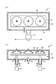
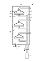
ここで本発明に係る成膜装置は、図1〜図7に示したように、扁平な円筒状の真空容器1内に載置台2と天板部材22との組を周方向に配置する場合(真空容器1と中心を同じくする円の円周上に各載置台2の中心を位置させる場合)に限定されない。例えば図14(a)、図14(b)に示す成膜装置のように、細長い矩形状の載置台2上に横一列にウエハWの載置領域を設け、これらの載置領域に対向するように天板部材22を設け、これらの部材を共通の排気口61を備えた排気空間10を成す真空容器1内に格納してもよい。また図15に示す成膜装置のように互いに対向する載置台2と天板部材22との複数の組を上下方向に配置し、排気空間10を成す真空容器1内にこれらを格納した構成としてもよい。なお、当該例を含む以下に説明する成膜装置、載置台2などの各例においては、既述の図1〜図7に示した成膜措置と同じ役割を果たす構成要素には、これらの図に記載した符号と同じ符号を付してある。   Here, in the film forming apparatus according to the present invention, as shown in FIGS. 1 to 7, a set of the mounting table 2 and the top plate member 22 is arranged in the circumferential direction in a flat cylindrical vacuum vessel 1. It is not limited to (when the center of each mounting table 2 is positioned on the circumference of a circle having the same center as that of the vacuum vessel 1). For example, as in the film forming apparatus shown in FIGS. 14A and 14B, the wafer W mounting regions are provided in a horizontal row on the elongated rectangular mounting table 2 so as to face these mounting regions. Thus, the top plate member 22 may be provided, and these members may be stored in the vacuum container 1 that forms the exhaust space 10 having the common exhaust port 61. Further, as in the film forming apparatus shown in FIG. 15, a plurality of sets of the mounting table 2 and the top plate member 22 facing each other are arranged in the vertical direction, and these are stored in the vacuum container 1 forming the exhaust space 10. Also good. It should be noted that in each example such as the film forming apparatus described below and the mounting table 2 including the example, the constituent elements that play the same role as the film forming measures shown in FIGS. The same reference numerals as those shown in FIG.

また載置台2と天板部材22との間の隙間は、図4などを用いて説明した載置台2の上面と天板部材22の下端部との間に形成されるものに限定されない。例えば図16に示すように、ウエハWの載置領域を上方側へ突出させた載置台2を天板部材22の凹部内に嵌合させて処理空間20を形成し、天板部材22の内壁面と載置台2との間に形成される隙間を介して処理空間20内の各種ガスを排気する構成としてもよい。   Further, the gap between the mounting table 2 and the top plate member 22 is not limited to that formed between the upper surface of the mounting table 2 and the lower end portion of the top plate member 22 described with reference to FIG. For example, as shown in FIG. 16, the processing table 20 is formed by fitting the mounting table 2 in which the mounting region of the wafer W protrudes upward into the recess of the top plate member 22. Various gases in the processing space 20 may be exhausted through a gap formed between the wall surface and the mounting table 2.

さらに処理空間20内の反応ガス等を排気空間10へと排気する排気用開口部は既述の成膜装置のように載置台2と天板部材22との間の隙間に限定されない。例えば図17(a)、図17(b)に示すように天板部材22を下面が開放された扁平な円筒形状に構成し、例えば当該天板部材22の側周壁部分に開口部223を設け、処理空間20内の反応ガスなどをこの開口部223を介して排気空間10へと排気するようにしてもよい。また、図18(a)、図18(b)に示すように載置台のウエハWが載置される載置領域の周囲に開口部27を設け、ここから排気空間10へと反応ガスなどを排気するようにしてもよい。   Further, the exhaust opening for exhausting the reaction gas or the like in the processing space 20 to the exhaust space 10 is not limited to the gap between the mounting table 2 and the top plate member 22 as in the film forming apparatus described above. For example, as shown in FIGS. 17A and 17B, the top plate member 22 is formed in a flat cylindrical shape with the bottom surface opened, and for example, an opening 223 is provided in a side peripheral wall portion of the top plate member 22. The reaction gas or the like in the processing space 20 may be exhausted to the exhaust space 10 through the opening 223. Further, as shown in FIGS. 18A and 18B, an opening 27 is provided around the mounting area on which the wafer W of the mounting table is mounted, and a reactive gas or the like is supplied from here to the exhaust space 10. You may make it exhaust.

ここで反応ガスは2種類である場合に限定されない。例えばチタン酸ストロンチウム(SrTiO)を成膜する場合のように3種類の反応ガス、例えばSr原料であるSr(THD)(ストロンチウムビステトラメチルヘプタンジオナト)と、Ti原料であるTi(OiPr)(THD)(チタニウムビスイソプロポキサイドビステトラメチルヘプタンジオナト)と、これらの酸化ガスであるオゾンガスとを用いてALDにより成膜を行うプロセスにも本成膜装置は適用することができる。この場合には、処理空間20に切り替えて供給される3種類の反応ガスのうち、引き続いて供給される2つの原料ガスの一方側を第1の反応ガス、他方側を第2の反応ガスと考えるとよい。即ち、Sr(THD)ガス→Ti(OiPr)(THD)ガス→オゾンガスの順に反応ガスが供給される場合には(パージガスの供給については省略してある)、Sr(THD)ガスとTi(OiPr)(THD)ガスとの関係においては前者が第1の反応ガス、後者が第2の反応ガスとなり、Ti(OiPr)(THD)ガスとオゾンガスとの関係においては、前者が第1の反応ガス、後者が第2の反応ガスとなる。そしてオゾンガスとSr(THD)ガスとの関係においては前者が第1の反応ガス、後者が第2の反応ガスとなると考えるとよい。4種類以上の反応ガスを用いて成膜する場合にも同様である。 Here, the reaction gas is not limited to two types. For example, when forming a film of strontium titanate (SrTiO 3 ), three kinds of reaction gases, for example, Sr (THD) 2 (strontium bistetramethylheptanedionate) as a Sr raw material and Ti (OiPr) as a Ti raw material are used. ) 2 (THD) 2 (titanium bisisopropoxide bistetramethylheptanedionate) and ozone gas, which is an oxidizing gas of these, can be applied to a process for forming a film by ALD. it can. In this case, of the three types of reaction gases supplied by switching to the processing space 20, one side of the two source gases to be subsequently supplied is the first reaction gas, and the other side is the second reaction gas. Think about it. That is, when the reaction gas is supplied in the order of Sr (THD) 2 gas → Ti (OiPr) 2 (THD) 2 gas → ozone gas (the supply of purge gas is omitted), Sr (THD) 2 gas And Ti (OiPr) 2 (THD) 2 gas, the former is the first reactive gas, the latter is the second reactive gas, and the relationship between Ti (OiPr) 2 (THD) 2 gas and ozone gas The former is the first reactive gas and the latter is the second reactive gas. In the relationship between ozone gas and Sr (THD) 2 gas, the former may be considered as the first reactive gas and the latter as the second reactive gas. The same applies to the case where a film is formed using four or more kinds of reaction gases.

また、載置台2と凹部を備えた天板部材22とを上下に対向させてウエハWの処理空間20を形成し、これらの部材2、22の隙間の幅を変えることにより処理空間20の圧力や当該処理空間20内における反応ガスの滞留時間を調整する既述の成膜装置は、いわゆるALDプロセス適用する場合のみに限定されない。例えば当該処理空間20内に反応ガスを連続的に供給してウエハW表面に成膜を行うCVD(Chemical Vapor Deposition)プロセスに対して本成膜装置を適用した場合にも、反応ガスの消費量を抑制するという効果は得ることができる。   Further, the processing space 20 of the wafer W is formed by vertically placing the mounting table 2 and the top plate member 22 provided with the concave portion, and the pressure of the processing space 20 is changed by changing the width of the gap between these members 2 and 22. In addition, the above-described film forming apparatus for adjusting the residence time of the reaction gas in the processing space 20 is not limited to the case where a so-called ALD process is applied. For example, even when this film forming apparatus is applied to a CVD (Chemical Vapor Deposition) process in which a reactive gas is continuously supplied into the processing space 20 to form a film on the surface of the wafer W, the consumption amount of the reactive gas The effect of suppressing the can be obtained.

この他、真空容器1内にて下部材である載置台2を上部材である天板部材22に対向させて処理空間20を形成し、例えば載置台2を昇降自在とすることにより、排気用開口部を成す載置台2と天板部材22との間の隙間の幅を調節可能とした構成の成膜装置は、真空容器1内に載置台2と天板部材22との複数の組を備え、前記の隙間を同じ幅に調節する場合に限定されない。例えば図19に示すように、真空容器1内に載置台2と天板部材22とを1組だけ備える成膜装置も本発明の技術的範囲に含まれる。また、真空容器1内にこれらの組を複数組備える成膜装置において、図20に示すように例えば各載置台2を独立して昇降可能な構成とし、各々の処理空間20における天板部材22との間の隙間の幅を異ならせることができるようにしてもよい。この場合には例えば処理空間20毎に前記の隙間の幅を異ならせて、例えば各種反応ガスの滞留時間や圧力を調節することにより膜質の異なる膜を成膜することができる。また、例えば処理空間20毎に異なる種類の反応ガスを供給し異なる種類の膜を成膜する際に、前記隙間が各々の反応ガスの種類に適した幅となるように載置台2を昇降させてもよい。   In addition, the processing space 20 is formed by making the mounting table 2 as the lower member face the top plate member 22 as the upper member in the vacuum container 1, and for example, by allowing the mounting table 2 to move up and down, The film forming apparatus having a configuration in which the width of the gap between the mounting table 2 forming the opening and the top plate member 22 can be adjusted includes a plurality of sets of the mounting table 2 and the top plate member 22 in the vacuum container 1. It is not limited to the case where the gap is adjusted to the same width. For example, as shown in FIG. 19, a film forming apparatus including only one set of the mounting table 2 and the top plate member 22 in the vacuum container 1 is also included in the technical scope of the present invention. Further, in the film forming apparatus provided with a plurality of these sets in the vacuum vessel 1, for example, as shown in FIG. 20, each mounting table 2 can be moved up and down independently, and the top plate member 22 in each processing space 20. You may enable it to vary the width | variety of the clearance gap between. In this case, for example, films having different film qualities can be formed by changing the width of the gap for each processing space 20 and adjusting the residence time and pressure of various reaction gases, for example. Further, for example, when different types of reaction gas are supplied to each processing space 20 to form different types of films, the mounting table 2 is moved up and down so that the gap has a width suitable for each type of reaction gas. May be.

マニホールド部3の構成としては、図14(a)(b)に示したように横一列に配列された処理空間20にガスを供給するものであってもよく、図21(a)(b)はそのようなマニホールド部3の一例を示している。このマニホールド部3のガス拡散室33は、処理空間20の配列に対応して、当該処理空間20の配列方向に伸びるように形成されている。   As a configuration of the manifold unit 3, gas may be supplied to the processing spaces 20 arranged in a horizontal row as shown in FIGS. Shows an example of such a manifold portion 3. The gas diffusion chambers 33 of the manifold portion 3 are formed so as to extend in the arrangement direction of the processing spaces 20 corresponding to the arrangement of the processing spaces 20.

ところでマニホールド部3によりガスが供給される各処理空間20の雰囲気は互いに気密に区画されてもよい。つまりマニホールド部3は、複数の真空容器内に夫々ガスを供給するように構成されていてもよい。また上記の各例ではマニホールド部3は成膜装置に設けられているが、例えばアッシング、エッチング、酸化処理、窒化処理装置などの真空雰囲気にてガス処理を行うガス処理装置に設けられ、そのガス処理に応じたガスを供給するようになっていてもよい。また、上述の成膜装置により処理される被処理基板は半導体ウエハWに限定されず、LCD(液晶ディスプレイ)用基板に代表されるFPD(フラットパネルディスプレイ)基板や、セラミックス基板等の他の基板であってもよい。   By the way, the atmosphere of each processing space 20 to which gas is supplied by the manifold unit 3 may be partitioned airtightly. That is, the manifold unit 3 may be configured to supply gas into each of the plurality of vacuum vessels. In each of the above examples, the manifold unit 3 is provided in the film forming apparatus. For example, the manifold unit 3 is provided in a gas processing apparatus that performs gas processing in a vacuum atmosphere, such as ashing, etching, oxidation processing, and nitriding processing equipment. A gas corresponding to the process may be supplied. The substrate to be processed by the above-described film forming apparatus is not limited to the semiconductor wafer W, and other substrates such as an FPD (flat panel display) substrate typified by an LCD (liquid crystal display) substrate and a ceramic substrate. It may be.

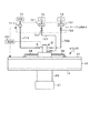
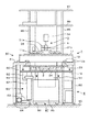
続いて大気雰囲気の工場内に据え付けられた状態の図1の成膜装置について、その外観構成を示した図22を参照しながら説明する。成膜装置はその真空容器1を構成する側壁部12及び天板11が支持部8によって平坦な床面8C上に支持されている。これ以降、このように支持部8に支持された成膜装置を成膜装置80と記載する。   Next, the film forming apparatus of FIG. 1 installed in a factory in an atmospheric atmosphere will be described with reference to FIG. 22 showing its external configuration. In the film forming apparatus, the side wall portion 12 and the top plate 11 constituting the vacuum vessel 1 are supported by a support portion 8 on a flat floor surface 8C. Hereinafter, the film forming apparatus supported by the support unit 8 in this way is referred to as a film forming apparatus 80.

支持部8は支持台81、支持脚82、横部材83及び固定部材84を備えている。前記真空容器1を構成する側壁部12の下端からは周方向に間隔をおいて外側方向に切片12aが突出しており、前記支持台81は真空容器1の周に沿って形成され、各切片12aの裏面を支持している。支持台81は真空容器1の底板14を後述のように下降させて側壁部12から分離するときに当該底板14と干渉しないように構成されている。   The support unit 8 includes a support base 81, support legs 82, a lateral member 83, and a fixing member 84. A section 12a protrudes outward from the lower end of the side wall portion 12 constituting the vacuum container 1 in the circumferential direction, and the support base 81 is formed along the circumference of the vacuum container 1, and each section 12a. Supports the back side. The support base 81 is configured not to interfere with the bottom plate 14 when the bottom plate 14 of the vacuum vessel 1 is lowered as described later and separated from the side wall portion 12.

成膜装置80において搬送口15の開口方向を奥側とすると、支持台81の左右の縁部において手前側から奥側に向かって間隔をおいて複数本の支持脚82が設けられ、各支持脚82は下方に向かって伸びている。そして、真空容器1から見て左側、右側に夫々形成された支持脚82の下端は夫々手前側から奥側に向かう横部材83により互いに連結されており、横部材83の下側及び支持脚82の下側には床面8Cにこれら支持脚82及び横部材83を固定するための複数の固定部材84が互いに間隔をおいて設けられている。   Assuming that the opening direction of the transfer port 15 is the back side in the film forming apparatus 80, a plurality of support legs 82 are provided at intervals on the left and right edges of the support base 81 from the near side to the back side. The leg 82 extends downward. The lower ends of the support legs 82 formed on the left side and the right side when viewed from the vacuum container 1 are connected to each other by a horizontal member 83 that extends from the front side to the back side. A plurality of fixing members 84 for fixing the support legs 82 and the lateral members 83 to the floor surface 8C are provided below the floor 8C at intervals.

奥側の左右に設けられた支持脚82は支持台81の上側に延長されるように伸び、その延長された部分は支柱85を構成しており、支柱85は支持板86、上板87を下からこの順に支持している。支持板86上には例えば成膜装置の電源ユニット等の機器類が配置されている。また、図示は省略しているが、成膜装置80は着脱自在の側板によりその外周を囲まれ、その側板は上板87と共に当該成膜装置80内にパーティクルが進入することを防いでいる。   The support legs 82 provided on the left and right sides of the back side extend so as to extend to the upper side of the support base 81, and the extended portion constitutes a support column 85, and the support column 85 includes a support plate 86 and an upper plate 87. It supports in this order from the bottom. On the support plate 86, for example, devices such as a power supply unit of the film forming apparatus are arranged. Although not shown, the outer periphery of the film forming apparatus 80 is surrounded by a detachable side plate, which prevents the particles from entering the film forming apparatus 80 together with the upper plate 87.

各支持脚82及び横部材83により囲まれた、真空容器1の下方空間8Aには真空容器1の底板14の裏面を保持する保持部91が設けられている。
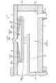
図23(a)は底板14の下側、図23(b)は保持部91の上側を夫々示している。図23(b)に示すように保持部91は開口部92を備え、前記スリーブ25及び駆動部51を囲むように筒状に形成されている。そして保持部91の上端には当該保持部91の周方向に沿って環状の突起93が形成されており、前記底板14の下方側には当該底板14中央部から下方に突出したスリーブ25及び駆動部51を囲むように前記突起93の形状に対応した溝94が形成されている。突起93と溝94とは互いに嵌合し、底板14に対して保持部91は位置決めされている。
A holding portion 91 that holds the back surface of the bottom plate 14 of the vacuum vessel 1 is provided in the lower space 8 </ b> A of the vacuum vessel 1 surrounded by the support legs 82 and the lateral members 83.
23A shows the lower side of the bottom plate 14, and FIG. 23B shows the upper side of the holding portion 91, respectively. As shown in FIG. 23B, the holding portion 91 includes an opening 92 and is formed in a cylindrical shape so as to surround the sleeve 25 and the driving portion 51. An annular protrusion 93 is formed at the upper end of the holding portion 91 along the circumferential direction of the holding portion 91, and the sleeve 25 protruding downward from the center portion of the bottom plate 14 and the drive are provided on the lower side of the bottom plate 14. A groove 94 corresponding to the shape of the protrusion 93 is formed so as to surround the portion 51. The protrusion 93 and the groove 94 are fitted to each other, and the holding portion 91 is positioned with respect to the bottom plate 14.

保持部91の下方には昇降機構95が設けられている。昇降機構95は例えば保持部91を垂直に昇降させるための油圧シリンダを備えており、その保持部91の昇降に伴って真空容器1の底板14と、この底板14に支柱24を介して設けられた載置台2が昇降する。また、昇降機構95の下側には転動体であるキャスタ96を備えた台車部97が設けられている。移動体である前記台車部97により昇降機構95が床面8C上を移動できるようになっており、この昇降機構95の移動に伴って保持部91も床面8C上を移動する。つまり、昇降機構95、保持部91及び底板14は互いに位置合わせされた状態で床面8Cを移動できるように構成されている。   A lifting mechanism 95 is provided below the holding portion 91. The elevating mechanism 95 includes, for example, a hydraulic cylinder for elevating the holding portion 91 vertically. The elevating mechanism 95 is provided with the bottom plate 14 of the vacuum vessel 1 along with the raising and lowering of the holding portion 91, and the bottom plate 14 via the support 24. The mounting table 2 moves up and down. Also, below the elevating mechanism 95, a cart 97 including a caster 96 that is a rolling element is provided. The lift mechanism 95 can move on the floor surface 8 </ b> C by the carriage part 97 that is a moving body, and the holding part 91 also moves on the floor surface 8 </ b> C as the lift mechanism 95 moves. That is, the lifting mechanism 95, the holding portion 91, and the bottom plate 14 are configured to be able to move on the floor surface 8C while being aligned with each other.

また、下方空間8Aには真空容器1の底板14に接続された排気管62が引き回されている。図中62aは排気管62の上流側と下流側とを接続する継手である。下方空間8Aの手前側には装置のユーザが乗り、装置の各部を操作するための踏み台8Bが配置されている。   Further, an exhaust pipe 62 connected to the bottom plate 14 of the vacuum vessel 1 is routed in the lower space 8A. In the figure, 62a is a joint that connects the upstream side and the downstream side of the exhaust pipe 62. On the front side of the lower space 8A, there is disposed a step 8B for a user of the apparatus to operate and operate each part of the apparatus.

続いて、既述の成膜装置80の真空容器1内を開放してメンテナンスを行う手順について説明する。処理空間20への各ガス供給及び処理空間20からの排気を停止させ、成膜処理を停止させた後、踏み台8Bを下方空間8Aの手前から、例えば左右いずれかに移動させて、下方空間8Aの手前側を開放する。そして、継手62aに接続された排気管62の上流側を当該継手62aから取り外す。そして、この継手62aと継手62aに接続された排気管62の下流側を、底板14を下降させるときに底板14と共に下降する排気管62の上流側に干渉しないように適切な位置に移動させておく。   Next, a procedure for performing maintenance by opening the vacuum container 1 of the film forming apparatus 80 described above will be described. After the gas supply to the processing space 20 and the exhaust from the processing space 20 are stopped and the film forming process is stopped, the step 8B is moved from the front of the lower space 8A to, for example, either the left or right side, thereby lowering the lower space 8A. Open the front side of. Then, the upstream side of the exhaust pipe 62 connected to the joint 62a is removed from the joint 62a. Then, the downstream side of the exhaust pipe 62 connected to the joint 62a and the joint 62a is moved to an appropriate position so as not to interfere with the upstream side of the exhaust pipe 62 descending together with the bottom plate 14 when the bottom plate 14 is lowered. deep.

その後、底板14と側壁部12とを接続するねじなどの不図示の留め具を取り外した後、図24に示すように昇降機構95によって保持部91を介して真空容器1の底板14を下降させ、底板14に接続された載置台2を、その上面の高さが側壁部12を支持する支持台81の下端よりも低くなるように位置させる。然る後、図25に示すように台車部97を利用して昇降機構95及び保持部91を真空容器1の下方空間8Aの手前側に引き出し、その昇降機構95及び支持部91の移動に伴って底板14、載置台2、支持腕23、支柱24及び排気管62の上流側が下方空間8Aから引き出される。   Then, after removing a fastener (not shown) such as a screw connecting the bottom plate 14 and the side wall portion 12, the bottom plate 14 of the vacuum vessel 1 is lowered by the lifting mechanism 95 via the holding portion 91 as shown in FIG. The mounting table 2 connected to the bottom plate 14 is positioned such that the height of the upper surface is lower than the lower end of the support table 81 that supports the side wall portion 12. Thereafter, as shown in FIG. 25, the lifting mechanism 95 and the holding portion 91 are pulled out to the near side of the lower space 8 </ b> A of the vacuum container 1 by using the cart portion 97, and the lifting mechanism 95 and the support portion 91 are moved. The upstream side of the bottom plate 14, the mounting table 2, the support arm 23, the support column 24, and the exhaust pipe 62 is drawn out from the lower space 8A.

そして、このように下方空間8Aから取り出された底板14及びそれに付随する各部材をユーザは手拭洗浄したり、あるいは取り出された各部を分解して所定の洗浄装置により洗浄し、反応ガスによる付着物を除去する。また、このように底板14を真空容器1から取り外したときに、図26に示すように真空容器1の下側が下方空間8Aに開放されている。ユーザはこの下方空間8Aを介して、開放された真空容器1の下側から真空容器1内の各部を手拭洗浄したり、各部品を取り外して洗浄装置により洗浄して、前記付着物を除去する。また、ユーザはこのような洗浄を行う他に、不具合のある部品を交換するなどの各種のメンテナンス作業を行う。   Then, the user manually cleans the bottom plate 14 taken out from the lower space 8A and the members associated therewith, or disassembles each part taken out and cleans it with a predetermined cleaning device, and deposits due to the reaction gas. Remove. Further, when the bottom plate 14 is detached from the vacuum vessel 1 in this way, the lower side of the vacuum vessel 1 is opened to the lower space 8A as shown in FIG. A user manually wipes and cleans each part in the vacuum container 1 from the lower side of the opened vacuum container 1 through the lower space 8A or removes each part and cleans it with a cleaning device to remove the deposits. . In addition to performing such cleaning, the user performs various maintenance operations such as replacing defective parts.

メンテナンス終了後、上記のように真空容器1から底板14を取り出したときとは逆の手順で底板14を真空容器1の下部に取り付けて、成膜装置80をメンテナンスを開始する前の状態に戻す。   After the maintenance is completed, the bottom plate 14 is attached to the lower part of the vacuum vessel 1 in the reverse procedure of taking out the bottom plate 14 from the vacuum vessel 1 as described above, and the film forming apparatus 80 is returned to the state before starting the maintenance. .

なお、この成膜装置の真空容器1は従来の成膜装置のように天板11を側壁12から取り外し、当該真空容器1の上側を開放することができる。また、天板11には各処理空間20に対応した位置に、この天板11から取り外し可能な蓋部材11aが設けられている。蓋部材11aの下方側は処理空間20を形成する天板部材22に接続されており、蓋部材11aと共に天板部材22を真空容器1から引き出すことができる。そしてこれら蓋部材11a及び天板部材22を取り外すことで、載置台2を露出させ、真空容器1の内部を上記のように洗浄してメンテナンスを行うことができる。このように天板11や蓋部材11aを取り外すときには、背景技術の欄で説明したように各供給管から液体原料及び反応ガスを除去し、各ガス供給管34を天板11から取り外しておく必要がある。そのように天板11や蓋部材11aを取り外してメンテナンスを行うのは例えば下方からの手拭洗浄では十分に生成物を除去しきれない場合や部材を交換する場合などが考えられる。   In addition, the vacuum vessel 1 of this film-forming apparatus can remove the top plate 11 from the side wall 12 and open | release the upper side of the said vacuum vessel 1 like the conventional film-forming apparatus. The top plate 11 is provided with a lid member 11 a that can be removed from the top plate 11 at a position corresponding to each processing space 20. The lower side of the lid member 11a is connected to a top plate member 22 that forms the processing space 20, and the top plate member 22 can be pulled out of the vacuum vessel 1 together with the lid member 11a. Then, by removing the lid member 11a and the top plate member 22, the mounting table 2 can be exposed, and the inside of the vacuum vessel 1 can be cleaned as described above for maintenance. Thus, when removing the top plate 11 or the lid member 11a, it is necessary to remove the liquid raw material and the reactive gas from each supply pipe and to remove each gas supply pipe 34 from the top plate 11 as described in the background art section. There is. For example, when the top plate 11 and the lid member 11a are removed for maintenance as described above, the product may not be sufficiently removed by hand wiping from below, or the member may be replaced.

この真空処理装置の一実施形態である成膜装置80によれば、真空容器1の天板11及び側壁部12に対して着脱自在に設けられ、ウエハWを載置する載置台2を備えた真空容器1の底板14と、この底板14を昇降させる昇降機構95と、この昇降機構95を搭載し、床面8Cに沿って移動可能な台車部97と、を備えているので、側壁部12から底板14及び載置台2を取り外し、これら側壁部12、底板14及び載置台2の夫々のメンテナンスを実施可能な位置に移動させることができる。従って、天板11を真空容器1から取り外す必要が無いので、この取り外しによるマニホールド部3に夫々液体原料及び反応ガスを供給する各供給管からこれら液体原料及び反応ガスを除去する必要が無くなる。その結果として装置のメンテナンス作業を容易に行うことができる。   According to the film forming apparatus 80 as an embodiment of the vacuum processing apparatus, the mounting apparatus 2 is provided that is detachably provided on the top plate 11 and the side wall 12 of the vacuum vessel 1 and on which the wafer W is mounted. The side wall 12 is provided with the bottom plate 14 of the vacuum vessel 1, a lifting mechanism 95 that lifts and lowers the bottom plate 14, and a carriage 97 that is mounted with the lifting mechanism 95 and is movable along the floor surface 8 </ b> C. Then, the bottom plate 14 and the mounting table 2 can be removed and moved to positions where maintenance of the side wall portion 12, the bottom plate 14 and the mounting table 2 can be performed. Therefore, since it is not necessary to remove the top plate 11 from the vacuum vessel 1, it is not necessary to remove these liquid source and reaction gas from the supply pipes for supplying the liquid source and reaction gas to the manifold portion 3 by this removal. As a result, the maintenance work of the apparatus can be easily performed.

ところで、上記のように下方空間8Aの外内に移動される保持部91、昇降機構95、載置台2及び底板14を含むユニットを複数用意し、一のユニットのメンテナンス中には他のユニットを真空容器1に取り付けて成膜処理を行い、他のユニットのメンテナンス中には一のユニットを真空容器1に取り付けて成膜処理を行うことで、前記ユニットのメンテナンスにおける装置の稼働率の低下を抑えていてもよい。   By the way, as described above, a plurality of units including the holding portion 91, the elevating mechanism 95, the mounting table 2, and the bottom plate 14 that are moved into the outside of the lower space 8A are prepared. The film forming process is performed by attaching to the vacuum container 1, and one unit is attached to the vacuum container 1 and performing the film forming process during maintenance of other units, thereby reducing the operating rate of the apparatus in the maintenance of the unit. It may be suppressed.

続いて上記の成膜装置80を例えば4基含んだ半導体製造装置100Aの構成について図27を参照しながら説明する。半導体製造装置100Aは、ウエハWのロード、アンロードを行うローダモジュールを構成する第1の搬送室102と、ロードロック室103a、103bと、真空搬送室モジュールである第2の搬送室104と、を備えている。第1の搬送室102の正面にはキャリアCが載置されるロードポート105が設けられており、第1の搬送室102の正面壁には、前記ロードポート105に載置されたキャリアCが接続されて、当該キャリアCの蓋と一緒に開閉されるゲートドアGTが設けられている。そして第2の搬送室104には、上述の成膜装置80が気密に接続されている。   Next, the configuration of a semiconductor manufacturing apparatus 100A including, for example, four film forming apparatuses 80 will be described with reference to FIG. The semiconductor manufacturing apparatus 100A includes a first transfer chamber 102 that constitutes a loader module that loads and unloads wafers W, load lock chambers 103a and 103b, a second transfer chamber 104 that is a vacuum transfer chamber module, It has. A load port 105 on which the carrier C is placed is provided in front of the first transfer chamber 102, and the carrier C placed on the load port 105 is placed on the front wall of the first transfer chamber 102. A gate door GT that is connected and opened and closed together with the lid of the carrier C is provided. The above-described film forming apparatus 80 is airtightly connected to the second transfer chamber 104.

また、第1の搬送室102の側面には、ウエハWの向きや偏心の調整を行うアライメント室106が設けられている。ロードロック室103a、103bには、夫々図示しない真空ポンプとリーク弁とが設けられており、大気雰囲気と真空雰囲気とを切り替えられるように構成されている。つまり、第1の搬送室102及び第2の搬送室104の雰囲気がそれぞれ大気雰囲気及び真空雰囲気に保たれているため、ロードロック室103a、103bは、それぞれの搬送室間において、ウエハWを搬送する時に雰囲気を調整するためのものである。なお図中Gは、ロードロック室103a、103bと第1の搬送室102または第2の搬送室104との間、あるいは第2の搬送室104と前記成膜装置80の搬送口15との間を仕切るゲートバルブ(仕切り弁)である。   An alignment chamber 106 for adjusting the orientation and eccentricity of the wafer W is provided on the side surface of the first transfer chamber 102. Each of the load lock chambers 103a and 103b is provided with a vacuum pump and a leak valve (not shown) so as to be switched between an air atmosphere and a vacuum atmosphere. That is, since the atmospheres of the first transfer chamber 102 and the second transfer chamber 104 are maintained in an air atmosphere and a vacuum atmosphere, respectively, the load lock chambers 103a and 103b transfer the wafer W between the transfer chambers. When adjusting the atmosphere. In the figure, G denotes between the load lock chambers 103a and 103b and the first transfer chamber 102 or the second transfer chamber 104, or between the second transfer chamber 104 and the transfer port 15 of the film forming apparatus 80. It is a gate valve (partition valve) which partitions off.

第1の搬送室102、第2の搬送室104には、夫々第1の搬送手段107、第2の搬送手段108a,108bが設けられている。第1の搬送手段107は、キャリアCとロードロック室103a,103bとの間及び第1の搬送室102とアライメント室106との間でウエハWの受け渡しを行うための搬送アームである。第2の搬送手段108a,108bは、ロードロック室103a,103bと成膜装置との間でウエハWの受け渡しを行うための搬送アームである。   The first transfer chamber 102 and the second transfer chamber 104 are provided with a first transfer means 107 and second transfer means 108a and 108b, respectively. The first transfer means 107 is a transfer arm for transferring the wafer W between the carrier C and the load lock chambers 103 a and 103 b and between the first transfer chamber 102 and the alignment chamber 106. The second transfer means 108a and 108b are transfer arms for transferring the wafer W between the load lock chambers 103a and 103b and the film forming apparatus.

キャリアCが半導体製造装置100Aに搬送されて、ロードポート105に載置され、第1の搬送室102に接続される。次いでゲートドアGTおよびキャリアCの蓋が同時に開かれて、キャリアC内のウエハWは第1の搬送手段107によって第1の搬送室102内に搬入され、次いでアライメント室106に搬送されて、その向きや偏心の調整が行われた後、ロードロック室103a(または103b)に搬送される。ロードロック室103a(または103b)内の圧力が調整された後、ウエハWは第2の搬送手段108aまたは搬送手段108bによってロードロック室103から第2の搬送室104に搬入される。続いて成膜装置80のゲートバルブGが開かれ、第2の搬送手段108a(または108b)はウエハWをその成膜装置80に搬送する。   The carrier C is transferred to the semiconductor manufacturing apparatus 100 </ b> A, placed on the load port 105, and connected to the first transfer chamber 102. Next, the gate door GT and the lid of the carrier C are simultaneously opened, and the wafer W in the carrier C is loaded into the first transfer chamber 102 by the first transfer means 107, and then transferred to the alignment chamber 106, and the orientation thereof. After the adjustment of the eccentricity is carried out, it is transferred to the load lock chamber 103a (or 103b). After the pressure in the load lock chamber 103a (or 103b) is adjusted, the wafer W is loaded into the second transfer chamber 104 from the load lock chamber 103 by the second transfer means 108a or the transfer means 108b. Subsequently, the gate valve G of the film forming apparatus 80 is opened, and the second transfer means 108a (or 108b) transfers the wafer W to the film forming apparatus 80.

成膜装置80により上述の成膜処理が終わると、その成膜装置80のゲートバルブGが開かれ、第2の搬送手段108a(108b)が当該成膜装置80の真空容器1内に進入する。既述の動作で処理の施されたウエハWが第2の搬送手段108a(108b)に受け渡され、然る後、第2の搬送手段108a(108b)は、ロードロック室103a(または103b)を介して第1の搬送手段107にウエハWを受け渡す。そして、第1の搬送手段107がキャリアCにウエハWを戻す。   When the above-described film forming process is completed by the film forming apparatus 80, the gate valve G of the film forming apparatus 80 is opened, and the second transfer means 108a (108b) enters the vacuum container 1 of the film forming apparatus 80. . The wafer W processed in the above-described operation is transferred to the second transfer means 108a (108b), and then the second transfer means 108a (108b) is loaded in the load lock chamber 103a (or 103b). Then, the wafer W is delivered to the first transfer means 107. Then, the first transfer means 107 returns the wafer W to the carrier C.

実施の形態に係る成膜装置の縦断面図である。It is a longitudinal cross-sectional view of the film-forming apparatus which concerns on embodiment. 上記成膜装置の内部の概略構成を示す斜視図である。It is a perspective view which shows schematic structure inside the said film-forming apparatus. 上記成膜装置の横断平面図である。It is a cross-sectional top view of the said film-forming apparatus. 上記成膜装置における処理領域を示す縦断面図である。It is a longitudinal cross-sectional view which shows the process area | region in the said film-forming apparatus. 上記処理領域を構成する天板部材を示す底面図である。It is a bottom view which shows the top-plate member which comprises the said process area | region. インジェクタの縦断面図である。It is a longitudinal cross-sectional view of an injector. 上記成膜装置のガス供給経路図である。It is a gas supply path | route figure of the said film-forming apparatus. 上記成膜装置の第1の作用図である。It is a 1st operation | movement figure of the said film-forming apparatus. 上記成膜装置の第2の作用図である。It is a 2nd operation | movement figure of the said film-forming apparatus. 上記成膜装置による成膜処理のガス供給シーケンス図である。It is a gas supply sequence figure of the film-forming process by the said film-forming apparatus. ガスがマニホールド部から処理空間に向かう様子を示した説明図である。It is explanatory drawing which showed a mode that gas went to a process space from a manifold part. 上記成膜装置の第3の作用図である。It is a 3rd operation | movement figure of the said film-forming apparatus. 上記成膜装置の作用に係る説明図である。It is explanatory drawing which concerns on the effect | action of the said film-forming apparatus. 上記成膜装置の変形例を示す横断平面図及び縦断側面図である。It is the cross-sectional top view and vertical side view which show the modification of the said film-forming apparatus. 上記成膜装置の他の変形例を示す縦断側面図である。It is a vertical side view which shows the other modification of the said film-forming apparatus. 載置台及び天板部材の他の例を示す縦断側面図である。It is a vertical side view which shows the other example of a mounting base and a top-plate member. 天板部材のさらに他の例を示す説明図である。It is explanatory drawing which shows the other example of a top-plate member. 載置台のさらに他の例を示す説明図である。It is explanatory drawing which shows the further another example of a mounting base. 上記成膜装置のさらに他の例を示す縦断側面図である。It is a vertical side view which shows the other example of the said film-forming apparatus. 上記成膜装置のこの他の例を示す縦断側面図である。It is a vertical side view which shows the other example of the said film-forming apparatus. マニホールド部の他の一例を示す説明図である。It is explanatory drawing which shows another example of a manifold part. 支持部に支持された前記成膜装置の外観斜視図である。It is an external appearance perspective view of the said film-forming apparatus supported by the support part. 底板の下面側斜視図及び保持部の上面側斜視図である。It is the lower surface side perspective view of a bottom plate, and the upper surface side perspective view of a holding | maintenance part. 前記成膜装置の真空容器の底板の下降動作を示した作用図である。It is the effect | action figure which showed the downward movement of the bottom plate of the vacuum vessel of the said film-forming apparatus. 真空容器の下方空間から引き出された載置台及び底板を示した斜視図である。It is the perspective view which showed the mounting base and bottom plate withdraw | derived from the downward space of the vacuum vessel. 底板が外れた真空容器の下側斜視図である。It is a lower perspective view of the vacuum vessel with the bottom plate removed. 前記成膜装置を含んだ真空処理装置である。A vacuum processing apparatus including the film forming apparatus.

符号の説明Explanation of symbols

W ウエハ
1 真空容器
10 排気空間
14 底板
100 制御部
2 載置台
20 処理空間
21 ステージヒータ
22 天板部材
23 支持腕
24 支柱
3 マニホールド部
4 インジェクタ
64 真空ポンプ
7 ガス供給制御部
71 原料ガス供給源
72 酸素ガス供給源
73 パージガス供給源
721、731
圧力調整弁
712、722、732
開閉弁
W Wafer 1 Vacuum container 10 Exhaust space 14 Bottom plate 100 Control unit 2 Mounting table 20 Processing space 21 Stage heater 22 Top plate member 23 Support arm 24 Support column 3 Manifold unit 4 Injector 64 Vacuum pump 7 Gas supply control unit 71 Source gas supply source 72 Oxygen gas supply source 73 Purge gas supply sources 721 and 731
Pressure regulating valves 712, 722, 732
On-off valve

Claims (5)

真空容器内に形成された処理空間にて、基板に対して処理ガスを供給して処理を行う真空処理装置において、
前記真空容器の天井部及び側壁部を構成する容器本体と、
この容器本体に対して着脱自在に設けられ、基板を載置する載置台を備えた真空容器の底板部と、
前記真空容器の天井部に設けられ、前記載置台に載置された基板に前記処理ガスを供給するガス供給機構と、
前記真空処理装置が設置される床面に前記容器本体を支持する支持体と、
前記底板部を、容器本体に装着される上位置と、容器本体の下方側の下位置との間で昇降させる昇降部と、
この昇降部を搭載し、前記床面に沿って移動可能な移動体と、
を備えたことを特徴とする真空処理装置。
In a vacuum processing apparatus that performs processing by supplying a processing gas to a substrate in a processing space formed in a vacuum vessel,
A container body constituting the ceiling and side walls of the vacuum container;
A bottom plate portion of a vacuum vessel provided detachably with respect to the container main body and provided with a mounting table for mounting a substrate;
A gas supply mechanism that is provided on the ceiling of the vacuum vessel and supplies the processing gas to the substrate placed on the mounting table;
A support that supports the container body on the floor on which the vacuum processing apparatus is installed;
An elevating part that raises and lowers the bottom plate part between an upper position to be attached to the container body and a lower position on the lower side of the container body;
A movable body that is equipped with this lifting part and is movable along the floor surface;
A vacuum processing apparatus comprising:
前記移動体は、床面に沿って転動する転動体を備えていることを特徴とする請求項1記載の真空処理装置。   The vacuum processing apparatus according to claim 1, wherein the moving body includes a rolling element that rolls along the floor surface. 前記昇降部は、前記底板部を位置合わせした状態で保持するための保持部を備えていることを特徴とする請求項1または2記載の真空処理装置。   The vacuum processing apparatus according to claim 1, wherein the elevating part includes a holding part for holding the bottom plate part in an aligned state. 前記処理空間は載置台とその載置台上に当該載置台に対向して設けられる上部材により形成され、処理空間の周方向に沿って、当該処理空間内と処理空間の外部である前記真空容器内の雰囲気とを連通するための排気用開口部が形成されることを特徴とする請求項1ないし3のいずれか一つに記載の
真空処理装置。
The processing space is formed by a mounting table and an upper member provided on the mounting table so as to face the mounting table, and the vacuum container that is inside the processing space and outside the processing space along the circumferential direction of the processing space The vacuum processing apparatus according to any one of claims 1 to 3, wherein an exhaust opening for communicating with the atmosphere inside is formed.
前記載置台と上部材との組は真空容器内に複数設けられることを特徴とする請求項4記載の真空処理装置。   The vacuum processing apparatus according to claim 4, wherein a plurality of sets of the mounting table and the upper member are provided in the vacuum vessel.
JP2008254484A 2008-09-30 2008-09-30 Vacuum processing equipment Active JP5088284B2 (en)

Priority Applications (1)

Application Number Priority Date Filing Date Title
JP2008254484A JP5088284B2 (en) 2008-09-30 2008-09-30 Vacuum processing equipment

Applications Claiming Priority (1)

Application Number Priority Date Filing Date Title
JP2008254484A JP5088284B2 (en) 2008-09-30 2008-09-30 Vacuum processing equipment

Publications (2)

Publication Number Publication Date
JP2010087236A true JP2010087236A (en) 2010-04-15
JP5088284B2 JP5088284B2 (en) 2012-12-05

Family

ID=42250903

Family Applications (1)

Application Number Title Priority Date Filing Date
JP2008254484A Active JP5088284B2 (en) 2008-09-30 2008-09-30 Vacuum processing equipment

Country Status (1)

Country Link
JP (1) JP5088284B2 (en)

Cited By (5)

* Cited by examiner, † Cited by third party
Publication number Priority date Publication date Assignee Title
WO2012093806A2 (en) * 2011-01-04 2012-07-12 주식회사 원익아이피에스 Thin film vapor deposition method and thin film vapor deposition apparatus
CN103299398A (en) * 2011-01-04 2013-09-11 圆益Ips股份有限公司 Thin film vapor deposition method and thin film vapor deposition apparatus
JP2021525453A (en) * 2018-05-24 2021-09-24 東京エレクトロン株式会社 Multi-zone gas injection for control of gas phase radicals
CN113439328A (en) * 2019-02-27 2021-09-24 东京毅力科创株式会社 Substrate processing apparatus, substrate processing system, and method for aligning mounting table
CN113459135A (en) * 2021-07-08 2021-10-01 哈尔滨东安华孚机械制造有限公司 Clamping device for cylinder cover assembly line and working method

Families Citing this family (6)

* Cited by examiner, † Cited by third party
Publication number Priority date Publication date Assignee Title
US10998209B2 (en) 2019-05-31 2021-05-04 Applied Materials, Inc. Substrate processing platforms including multiple processing chambers
US11817331B2 (en) 2020-07-27 2023-11-14 Applied Materials, Inc. Substrate holder replacement with protective disk during pasting process
US11749542B2 (en) 2020-07-27 2023-09-05 Applied Materials, Inc. Apparatus, system, and method for non-contact temperature monitoring of substrate supports
US11600507B2 (en) 2020-09-09 2023-03-07 Applied Materials, Inc. Pedestal assembly for a substrate processing chamber
US11610799B2 (en) 2020-09-18 2023-03-21 Applied Materials, Inc. Electrostatic chuck having a heating and chucking capabilities
US11674227B2 (en) 2021-02-03 2023-06-13 Applied Materials, Inc. Symmetric pump down mini-volume with laminar flow cavity gas injection for high and low pressure

Citations (3)

* Cited by examiner, † Cited by third party
Publication number Priority date Publication date Assignee Title
JPH08218172A (en) * 1995-02-10 1996-08-27 Tokyo Electron Ltd Gas treating device
JPH1098002A (en) * 1996-09-19 1998-04-14 Kokusai Electric Co Ltd Quartz tube detaching/attaching device for vertical reactor
JP2006009144A (en) * 2004-05-21 2006-01-12 Ulvac Japan Ltd Vacuum film-forming apparatus

Patent Citations (3)

* Cited by examiner, † Cited by third party
Publication number Priority date Publication date Assignee Title
JPH08218172A (en) * 1995-02-10 1996-08-27 Tokyo Electron Ltd Gas treating device
JPH1098002A (en) * 1996-09-19 1998-04-14 Kokusai Electric Co Ltd Quartz tube detaching/attaching device for vertical reactor
JP2006009144A (en) * 2004-05-21 2006-01-12 Ulvac Japan Ltd Vacuum film-forming apparatus

Cited By (11)

* Cited by examiner, † Cited by third party
Publication number Priority date Publication date Assignee Title
WO2012093806A2 (en) * 2011-01-04 2012-07-12 주식회사 원익아이피에스 Thin film vapor deposition method and thin film vapor deposition apparatus
WO2012093806A3 (en) * 2011-01-04 2012-09-07 주식회사 원익아이피에스 Thin film vapor deposition method and thin film vapor deposition apparatus
CN103299398A (en) * 2011-01-04 2013-09-11 圆益Ips股份有限公司 Thin film vapor deposition method and thin film vapor deposition apparatus
US9506146B2 (en) 2011-01-04 2016-11-29 Wonik Ips Co., Ltd. Thin film vapor deposition method and thin film vapor deposition apparatus
KR101829669B1 (en) 2011-01-04 2018-02-19 주식회사 원익아이피에스 Method of depositing thin film and Apparatus for depositing thin film
JP2021525453A (en) * 2018-05-24 2021-09-24 東京エレクトロン株式会社 Multi-zone gas injection for control of gas phase radicals
JP7205021B2 (en) 2018-05-24 2023-01-17 東京エレクトロン株式会社 Multizone gas injection for control of gas-phase radicals
CN113439328A (en) * 2019-02-27 2021-09-24 东京毅力科创株式会社 Substrate processing apparatus, substrate processing system, and method for aligning mounting table
CN113439328B (en) * 2019-02-27 2024-04-16 东京毅力科创株式会社 Substrate processing apparatus, substrate processing system, and method for aligning stage
CN113459135A (en) * 2021-07-08 2021-10-01 哈尔滨东安华孚机械制造有限公司 Clamping device for cylinder cover assembly line and working method
CN113459135B (en) * 2021-07-08 2023-04-07 哈尔滨东安华孚机械制造有限公司 Clamping device for cylinder cover assembly line and working method

Also Published As

Publication number Publication date
JP5088284B2 (en) 2012-12-05

Similar Documents

Publication Publication Date Title
JP5544697B2 (en) Deposition equipment
JP5315898B2 (en) Deposition equipment
JP5088284B2 (en) Vacuum processing equipment
JP6095825B2 (en) Substrate processing apparatus and semiconductor device manufacturing method
US10131984B2 (en) Substrate processing apparatus
JP4803578B2 (en) Deposition method
JP5722595B2 (en) Substrate processing apparatus and semiconductor device manufacturing method
US8539908B2 (en) Film forming apparatus, film forming method and storage medium
JP5347294B2 (en) Film forming apparatus, film forming method, and storage medium
JP5284182B2 (en) Substrate processing apparatus and semiconductor device manufacturing method
JP2010199160A (en) Substrate processing apparatus
JP2011238832A (en) Substrate processing apparatus
JP5083153B2 (en) Vacuum processing equipment
JP2016117933A (en) Film deposition apparatus
KR20100031460A (en) Manufacturing method of ti system film and storage medium
JP2008218555A (en) METHOD OF FORMING SrTiO3 FILM AND COMPUTER-READABLE RECORDING MEDIUM
JP5751754B2 (en) Film formation method and storage medium
JP5095230B2 (en) Method for forming SrTiO3 film and computer-readable storage medium
JP6021977B2 (en) Substrate processing apparatus and semiconductor device manufacturing method
JP2009123950A (en) Substrate treating device
CN110277329B (en) Substrate processing apparatus
KR101512140B1 (en) Atomic layer deposition apparatus and method thereof
JP6108530B2 (en) Semiconductor device manufacturing method, program, and substrate processing apparatus
JP2008211106A (en) Manufacturing method of semiconductor device, and substrate processing apparatus

Legal Events

Date Code Title Description
A621 Written request for application examination

Free format text: JAPANESE INTERMEDIATE CODE: A621

Effective date: 20110808

A977 Report on retrieval

Free format text: JAPANESE INTERMEDIATE CODE: A971007

Effective date: 20120516

A131 Notification of reasons for refusal

Free format text: JAPANESE INTERMEDIATE CODE: A131

Effective date: 20120522

A521 Request for written amendment filed

Free format text: JAPANESE INTERMEDIATE CODE: A523

Effective date: 20120723

TRDD Decision of grant or rejection written
A01 Written decision to grant a patent or to grant a registration (utility model)

Free format text: JAPANESE INTERMEDIATE CODE: A01

Effective date: 20120814

A01 Written decision to grant a patent or to grant a registration (utility model)

Free format text: JAPANESE INTERMEDIATE CODE: A01

A61 First payment of annual fees (during grant procedure)

Free format text: JAPANESE INTERMEDIATE CODE: A61

Effective date: 20120827

FPAY Renewal fee payment (event date is renewal date of database)

Free format text: PAYMENT UNTIL: 20150921

Year of fee payment: 3

R150 Certificate of patent or registration of utility model

Ref document number: 5088284

Country of ref document: JP

Free format text: JAPANESE INTERMEDIATE CODE: R150

Free format text: JAPANESE INTERMEDIATE CODE: R150

R250 Receipt of annual fees

Free format text: JAPANESE INTERMEDIATE CODE: R250

R250 Receipt of annual fees

Free format text: JAPANESE INTERMEDIATE CODE: R250

R250 Receipt of annual fees

Free format text: JAPANESE INTERMEDIATE CODE: R250

R250 Receipt of annual fees

Free format text: JAPANESE INTERMEDIATE CODE: R250

R250 Receipt of annual fees

Free format text: JAPANESE INTERMEDIATE CODE: R250

R250 Receipt of annual fees

Free format text: JAPANESE INTERMEDIATE CODE: R250

R250 Receipt of annual fees

Free format text: JAPANESE INTERMEDIATE CODE: R250