JP2010086668A - Fuel cell - Google Patents
Fuel cell Download PDFInfo
- Publication number
- JP2010086668A JP2010086668A JP2008251164A JP2008251164A JP2010086668A JP 2010086668 A JP2010086668 A JP 2010086668A JP 2008251164 A JP2008251164 A JP 2008251164A JP 2008251164 A JP2008251164 A JP 2008251164A JP 2010086668 A JP2010086668 A JP 2010086668A
- Authority
- JP
- Japan
- Prior art keywords
- separator
- seal member
- gas
- diffusion layer
- fuel cell
- Prior art date
- Legal status (The legal status is an assumption and is not a legal conclusion. Google has not performed a legal analysis and makes no representation as to the accuracy of the status listed.)
- Granted
Links
Images


Classifications
-
- Y—GENERAL TAGGING OF NEW TECHNOLOGICAL DEVELOPMENTS; GENERAL TAGGING OF CROSS-SECTIONAL TECHNOLOGIES SPANNING OVER SEVERAL SECTIONS OF THE IPC; TECHNICAL SUBJECTS COVERED BY FORMER USPC CROSS-REFERENCE ART COLLECTIONS [XRACs] AND DIGESTS
- Y02—TECHNOLOGIES OR APPLICATIONS FOR MITIGATION OR ADAPTATION AGAINST CLIMATE CHANGE
- Y02E—REDUCTION OF GREENHOUSE GAS [GHG] EMISSIONS, RELATED TO ENERGY GENERATION, TRANSMISSION OR DISTRIBUTION
- Y02E60/00—Enabling technologies; Technologies with a potential or indirect contribution to GHG emissions mitigation
- Y02E60/30—Hydrogen technology
- Y02E60/50—Fuel cells
-
- Y—GENERAL TAGGING OF NEW TECHNOLOGICAL DEVELOPMENTS; GENERAL TAGGING OF CROSS-SECTIONAL TECHNOLOGIES SPANNING OVER SEVERAL SECTIONS OF THE IPC; TECHNICAL SUBJECTS COVERED BY FORMER USPC CROSS-REFERENCE ART COLLECTIONS [XRACs] AND DIGESTS
- Y02—TECHNOLOGIES OR APPLICATIONS FOR MITIGATION OR ADAPTATION AGAINST CLIMATE CHANGE
- Y02P—CLIMATE CHANGE MITIGATION TECHNOLOGIES IN THE PRODUCTION OR PROCESSING OF GOODS
- Y02P70/00—Climate change mitigation technologies in the production process for final industrial or consumer products
- Y02P70/50—Manufacturing or production processes characterised by the final manufactured product
Abstract
Description
この発明は、電解質層として固体高分子膜を用いた単電池を積層した燃料電池に関し、特に組立の作業性を向上した燃料電池に関する。 The present invention relates to a fuel cell in which unit cells using a solid polymer film as an electrolyte layer are stacked, and more particularly to a fuel cell with improved assembly workability.
燃料電池は、電解質層の両面に触媒層を配置し、そこに燃料と酸化剤を供給して電気化学反応により発電する装置である。たとえば、一般的な固体高分子型燃料電池では、イオン交換膜で形成された固体高分子膜の両面に白金あるいは白金化合物等からなる触媒層と多孔質カーボンペーパー等で構成されたガス拡散層を積層し、さらにその両側にガス供給用の流路と、発電により発生する熱を除去するための冷却水を供給する冷却水流路を備えたガス不透過性のセパレータを積層した構造をしている。また、各部材の積層面間には、ガスおよび冷却水が所定の流路から外部に流出するのを防止するためのシール部が設置されている。 A fuel cell is a device in which a catalyst layer is disposed on both sides of an electrolyte layer, and fuel and an oxidant are supplied to the catalyst layer to generate electricity by an electrochemical reaction. For example, in a general polymer electrolyte fuel cell, a catalyst layer made of platinum or a platinum compound and a gas diffusion layer made of porous carbon paper or the like are formed on both sides of a solid polymer membrane formed of an ion exchange membrane. It has a structure in which gas-impermeable separators are provided which are laminated and further have gas supply flow paths and cooling water flow paths for supplying cooling water for removing heat generated by power generation on both sides. . In addition, a seal portion for preventing gas and cooling water from flowing out from a predetermined flow path to the outside is provided between the laminated surfaces of the members.
ここで、積層面間のシール方法としては、所定形状の熱可塑性ポリマーを溶融させて各部材を接着する方法や、所定形状の弾力性のあるシール部材を挟み込む方法が提案されている(たとえば特許文献1参照)。 Here, as a sealing method between the laminated surfaces, a method of melting a thermoplastic polymer having a predetermined shape and bonding each member, and a method of sandwiching an elastic seal member having a predetermined shape have been proposed (for example, patents). Reference 1).
また、積層面間のシールに弾力性のあるシール部材を挟み込む方法で、シール部材の設置を簡略化する方法として、セパレータの両面のシール部材を接続してシール部材の断面を凹型に成型し、凹型のシール部材と凸型のセパレータ端部を嵌合することでガスケットを組み付ける方法が提案されている(たとえば特許文献2参照)。
しかしながら、ガス供給用の流路がセパレータの外周上の一部に達するように形成されたセパレータを使用する場合、特許文献1による弾力性のあるシール部材を挟み込む方法では、ガス供給用の流路がセパレータの外周に達している部分を避けてシール部材を設置する必要があり、一般的には、セパレータの燃料ガス流路溝が形成された面では燃料ガス流路の流れ方向に沿った2辺と、酸化剤ガス流路溝が形成された面では酸化剤ガス流路の流れ方向に沿った2辺とにシール部材が設置されるため、セパレータ1枚につきそれぞれ独立したシール部材を合計4枚設置する必要がある。この時、シール部材は弾性体であるために比較的容易に変形してしまうとともに、重量が小さいために作業中にシール部材が比較的容易に移動してしまい、所定の位置にシール部材を設置する作業が困難であった。
However, in the case of using a separator formed so that the gas supply flow path reaches a part of the outer periphery of the separator, the method of sandwiching the elastic seal member according to
また、シール部材をあらかじめセパレータに接着することでその移動を制限する方法もあるが、この場合は、接着剤の購入コストおよび接着作業のための作業コストが追加で必要となり、燃料電池全体の製造コストが高くなってしまうとともに、接着に使用した物質が溶出して燃料電池の性能を低下させるという課題がある。 In addition, there is a method of restricting the movement of the sealing member by adhering it to the separator in advance, but in this case, an additional cost for purchasing the adhesive and an operating cost for the adhering work are required, and the entire fuel cell is manufactured. There is a problem that the cost is increased and the material used for adhesion is eluted to lower the performance of the fuel cell.
また、セパレータの両面のシール部材を接続してシール部材の断面を凹型に成型し、シール部材の凹部とセパレータ端部の凸部を嵌合することでガスケットを組み付ける方法は、前述の通り、ガス供給用の流路がセパレータの外周上の一部に達するように形成されたセパレータを使用する場合に、セパレータの外周上のガス流路溝が凹型のシール部材により閉塞されてしまうために適用することが不可能である。 In addition, as described above, the method of assembling the gasket by connecting the seal members on both sides of the separator, molding the cross section of the seal member into a concave shape, and fitting the concave portion of the seal member and the convex portion of the separator end is as described above. When a separator formed so that the supply channel reaches a part on the outer periphery of the separator is used, the gas channel groove on the outer periphery of the separator is blocked by the concave seal member. It is impossible.
本発明は上記のような従来技術の問題点を解決するために提案されたものであり、その目的は、製造が容易であり低コストの固体高分子型燃料電池を提供することにある。 The present invention has been proposed in order to solve the above-described problems of the prior art, and an object thereof is to provide a solid polymer fuel cell that is easy to manufacture and low in cost.
上記目的を達成するために、本発明に係る燃料電池は、電解質層である固体高分子膜と、前記固体高分子膜をその両面から挟むようにして配置されたアノード触媒層およびカソード触媒層と、前記アノード触媒層およびカソード触媒層それぞれに接してこれらの触媒層を挟み込むように配置されたアノードガス拡散層およびカソードガス拡散層と、前記アノードガス拡散層およびカソードガス拡散層を挟み込むように配置されて、前記アノードガス拡散層と対向する位置に燃料ガス流路溝を形成し、前記カソードガス拡散層と対向する位置に酸化剤ガス流路溝を形成する、平板状でガス不透過性のセパレータと、前記セパレータと前記アノードガス拡散層とが対向する位置および前記セパレータと前記カソードガス拡散層とが対向する位置に挟み込まれるように配置されて、前記セパレータの両面の少なくとも二つの角部を包み込んで、セパレータの両面の、前記燃料ガス流路溝および酸化剤ガス流路溝を除く部分を覆うように構成され、弾性材料で形成されたシール部材と、を有する単電池を複数個積層した積層体を含むこと、を特徴とする。 In order to achieve the above object, a fuel cell according to the present invention comprises a solid polymer membrane as an electrolyte layer, an anode catalyst layer and a cathode catalyst layer disposed so as to sandwich the solid polymer membrane from both sides thereof, An anode gas diffusion layer and a cathode gas diffusion layer disposed so as to be in contact with and sandwiching the anode catalyst layer and the cathode catalyst layer, respectively, and an anode gas diffusion layer and a cathode gas diffusion layer are disposed between the anode catalyst diffusion layer and the cathode gas diffusion layer. A planar gas-impermeable separator that forms a fuel gas flow channel at a position facing the anode gas diffusion layer and an oxidant gas flow channel at a position facing the cathode gas diffusion layer; The separator and the anode gas diffusion layer are opposed to each other and the separator and the cathode gas diffusion layer are opposed to each other. It is arranged so as to be embedded, and is configured to wrap around at least two corners on both sides of the separator and to cover portions on both sides of the separator excluding the fuel gas passage groove and the oxidant gas passage groove. And a laminated body in which a plurality of unit cells having a sealing member made of an elastic material are laminated.
本発明によれば、積層面間のシール部材はセパレータに容易に取付けが可能となり、さらに、シール部材をあらかじめセパレータもしくはその他の部材に接着するなどしてシール部材の移動防止対策を講じる必要がなくなるため、製造コストの安い燃料電池を提供することができる。 According to the present invention, the sealing member between the laminated surfaces can be easily attached to the separator, and further, it is not necessary to take measures to prevent the sealing member from moving by, for example, bonding the sealing member to the separator or other members in advance. Therefore, a fuel cell with a low manufacturing cost can be provided.
以下、図面を参照して、本発明の実施形態について説明する。 Embodiments of the present invention will be described below with reference to the drawings.
[第1の実施形態]
図1ないし図10を参照して本発明に係る燃料電池の第1の実施形態について説明する。
[First Embodiment]
A first embodiment of a fuel cell according to the present invention will be described with reference to FIGS.
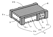
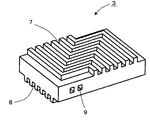
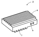
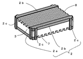
図1は本発明に係る燃料電池の第1の実施形態の積層体を示す展開斜視図、図2は図1の積層体の組み立て状態を示す立面図、図3は図2の膜電極複合体の模式的部分拡大立断面図である。図4は第1の実施形態における燃料電池を示す斜視図、図5は図4の燃料電池の平断面図である。さらに、図6は図1のセパレータとシール部材を燃料ガス流路溝側から見た斜視図、図7は図1のセパレータを酸化剤ガス流路溝側から見た斜視図、図8は図1のセパレータを燃料ガス流路溝側から見た斜視図、図9は図1のシール部材を酸化剤ガス流路溝側から見た斜視図、図10は図1のシール部材を燃料ガス流路溝側から見た斜視図である。
FIG. 1 is a developed perspective view showing a laminated body of a first embodiment of a fuel cell according to the present invention, FIG. 2 is an elevation view showing an assembled state of the laminated body of FIG. 1, and FIG. 3 is a membrane electrode composite of FIG. It is a typical partial expanded sectional view of a body. 4 is a perspective view showing the fuel cell according to the first embodiment, and FIG. 5 is a plan sectional view of the fuel cell of FIG. 6 is a perspective view of the separator and the seal member of FIG. 1 viewed from the fuel gas flow channel groove side, FIG. 7 is a perspective view of the separator of FIG. 1 viewed from the oxidant gas flow channel side, and FIG. 1 is a perspective view of the
図1および図4などに示すように、この実施形態の燃料電池は、長方形または正方形の膜電極複合体(MEA)1と、ガス不透過性の材料からなる長方形または正方形の平板状セパレータ3とを交互に積層した積層体4を備えている。また、各セパレータ3の両面にシール部材2が設置されている。膜電極複合体1とセパレータ3の組み合わせは単電池と呼ばれ、積層体4は単電池を積層したものであるといえる。
As shown in FIGS. 1 and 4, the fuel cell of this embodiment includes a rectangular or square membrane electrode assembly (MEA) 1 and a rectangular or square
また図4および図5に示すように、積層体4の周辺には酸化剤系ガスマニホールド5と燃料系ガスマニホールド6が設置されている。ここで、酸化剤系ガスマニホールド5と燃料系ガスマニホールド6とはそれぞれ積層体4に隣接して積層体4に対して開口部を持つ箱型の構造物であり、酸化ガス入口配管30と燃料ガス入口配管31を介して、それぞれ、酸化剤ガスおよび燃料ガスを外部から積層体4に供給するように構成されている。同様に、酸化剤ガス出口配管32と燃料ガス出口配管33を介して積層体4で消費されなかったガスを外部に排出する。
As shown in FIGS. 4 and 5, an oxidant-based
また、図示の構成では、酸化剤系ガスマニホールド5は仕切り板5aにより内部空間が2分割され、一方の空間は酸化剤ガスの供給または排出の流路を構成するとともに、他方の空間は積層体4の膜電極複合体1が発電に伴い発生した熱を除去するための冷却水が流通する流路を構成している。冷却水入口配管34と冷却水出口配管35を通して冷却水が外部から供給され、積層体4の冷却に使用された後に排出されるように構成されている。
In the configuration shown in the figure, the internal space of the oxidant-based
積層体4の両端面には締付板36が配置され、これらの締付板36同士がタイロッド37によって互いに近づく方向に締め付けられている。
Fastening
膜電極複合体1は、図3に示すように、電解質層である固体高分子膜20の両面に、固体高分子膜20を挟むようにして一対のアノード触媒層21とカソード触媒層22とを有し、アノード触媒層21とカソード触媒層22とを挟み込むようにしてアノードガス拡散層23とカソードガス拡散層24からなる一対のガス拡散層が配置されている。
As shown in FIG. 3, the
図1、図2および図5ないし図8に示すように、セパレータ3の両面にはそれぞれ酸化剤ガス流路溝7と燃料ガス流路溝8が形成されており、さらに、セパレータ3にはその内部を貫通して冷却水流路9が形成されている。
As shown in FIGS. 1, 2, and 5 to 8, an oxidant
シール部材2は、弾性材料からなり、図1、図6、図9および図10などに示すように、各シール部材2が一つのセパレータ3の両面を一体で包み込むように構成されている。ただし、セパレータ3の面上に形成された燃料ガス流路溝8および酸化剤ガス流路溝7がシール部材2で覆われることがないように構成されている。
The
シール部材2は、セパレータ3の酸化剤ガス流路溝7に沿って設置され酸化剤ガスが酸化剤系ガスマニホールド5の酸化剤流通路以外の部分に漏洩するのを防止する酸化剤系シール部2aと、セパレータ3の燃料ガス流路溝8に沿って設置され燃料ガスが燃料系ガスマニホールド6の燃料流通路以外の部分に漏洩するのを防止する燃料系シール部2bと、セパレータの4個の角部で酸化剤系シール部2aと燃料系シール部2bとを連結するシール部材接続部2cとから構成されている。
The
シール部材接続部2cは、酸化剤系ガスマニホールド5および燃料系ガスマニホールド6とセパレータ3により挟持されており酸化剤系ガスマニホールド5および燃料系ガスマニホールド6の内部を流通しているガスが外部に漏洩するのを防止している。さらに本図では、シール部材2に酸化剤系ガスマニホールド5の仕切り板5aとセパレータ3により挟持される位置に仕切り板のシール部2dが形成されており、冷却水系と酸化剤ガス系との間でガスおよび冷却水が移動するのを防止している。図示のシール部材接続部2cは、4個の角部の両面および、両面を接続する部分全体を覆っている。
The seal member connecting portion 2c is sandwiched between the
図示の例では、シール部材2の各部分は直方体またはその組み合わせでできており、各部分の横断面はいずれも長方形またはその組み合わせでできている。
In the illustrated example, each part of the
ここで、酸化剤系シール部2aと燃料系シール部2bとシール部材接続部2cおよび仕切り板のシール部2dはそれぞれ別々に成型された成型品を接着することで製造することも可能であるが、成型と接着のコストを考慮すると、初めから一体物として成型することが望ましい。また、シール部材2の材料としては、EPDM(エチレンプロピレンジエンゴム)やシリコンゴムなどが適用可能であるが、シール性の低下と材料からの溶出物が燃料電池の運転に影響を及ぼさない材料であればその他の単一の材料または複数の材料を組み合わせて使用してもよい。
Here, the oxidant seal part 2a, the fuel seal part 2b, the seal member connection part 2c, and the seal part 2d of the partition plate can be manufactured by adhering separately molded products. Considering the cost of molding and bonding, it is desirable to mold as a single piece from the beginning. Further, as the material of the
次に、上記の構成を有する第1の実施形態における作用について説明する。上記の構成を有する第1の実施形態では、セパレータ3とシール部材2を燃料系ガスマニホールド6の方向から見た時に、酸化剤系シール部2aの左右の端部にはシール部材接続部2cと燃料系シール部2bの端部が接続され、セパレータ3の燃料系ガスマニホールド6に面した端部の辺を包み込むように折り返した形状となっている。したがって、燃料系ガスマニホールド6の方向から見た時に、セパレータ3に設置されたシール部材2は上下左右の方向に移動することができない。
Next, the operation of the first embodiment having the above configuration will be described. In the first embodiment having the above-described configuration, when the
また、同様に、セパレータ3とシール部材2を酸化剤系ガスマニホールド5の方向から見た時に、燃料系シール部2bの左右の端部にはシール部材接続部2cと酸化剤系シール部2aの端部が接続され、セパレータ3の酸化剤系ガスマニホールド5に面した端部の辺を包み込むように折り返した形状となっている。したがって、酸化剤系ガスマニホールド5の方向から見た時に、セパレータ3に設置されたシール部材2は同様に上下左右の方向に移動することができない。
Similarly, when the
したがって、シール部材2を弾性変形させる程の外力が加わらない限り、シール部材2はいかなる方向にも移動できない状態でセパレータ3に設置されており、設置後のシール部材2の移動を防止するためにシール部材2をセパレータ3または膜電極複合体1にあらかじめ接着する必要がなくなる。
Therefore, the
また、シール部材2の取付け作業に関しては、シール部材2は弾性体から構成されているため、その弾性変形の範囲内でシール部材2を変形させシール部材2の折り返した形状となった部分にセパレータ3の4個の角部を嵌合させれば、シール部材2は再び元の形状に戻り、特別な位置合わせを必要とせずに所定の位置に設置することが可能となる。
Regarding the mounting operation of the
さらに、シール部材2のシール部材接続部2cと仕切り板のシール部2dにより積層体4と酸化剤系ガスマニホールド5および燃料系ガスマニホールド6の間のシール部が形成されるため、この部分に新たにシール部品を設置する必要がなくなる。
Further, since the seal member connecting portion 2c of the
以上説明したように、本実施形態では、シール部材2はいかなる方向にも移動できない状態でセパレータ3に設置されており、設置後のシール部材2の移動を防止するためにシール部材2をセパレータ3または膜電極複合体1にあらかじめ接着する必要がなくなる。したがって、接着剤の購入コストおよび接着作業のための作業コストが不要となり、1枚のセパレータ3につきそれぞれ独立したシール部材を複数枚設置する必要がなくなる上にシール部材2は特別な位置合わせを必要とせずに所定の位置に設置することが可能となる。これにより、シール部品の購入コストとシール部品の取付け作業時間が削減される。また、接着に使用した物質が溶出して燃料電池の性能を低下させるという問題が発生しないため、安価で高性能な燃料電池を提供することができる。
As described above, in the present embodiment, the
さらに、シール部材2のシール部材接続部2cと仕切り板のシール部2dにより積層体4と酸化剤系ガスマニホールド5および燃料系ガスマニホールド6の間のシール部が形成されるため、この部分に新たにシール部品を設置する必要がなくなり、シール部品の購入コストとシール部品の取付け作業時間が削減され、さらに安価な燃料電池を提供することができる。
Further, since the seal member connecting portion 2c of the
[第2の実施形態]
図11および図12を参照して本発明に係る燃料電池の第1の実施形態について説明する。ここで、第1の実施形態と同一または類似の構成部分には共通の符号を付し、重複する説明は省略する。
[Second Embodiment]
A first embodiment of the fuel cell according to the present invention will be described with reference to FIGS. 11 and 12. Here, the same or similar components as those in the first embodiment are denoted by common reference numerals, and redundant description is omitted.
図11は本発明に係る燃料電池の第2の実施形態におけるセパレータとシール部材を酸化剤ガス流路溝側から見た斜視図、図12は第2の実施形態におけるセパレータとシール部材を燃料ガス流路溝側から見た斜視図である。 FIG. 11 is a perspective view of the separator and the sealing member in the second embodiment of the fuel cell according to the present invention viewed from the oxidant gas flow channel groove side, and FIG. 12 shows the fuel gas in the separator and the sealing member in the second embodiment. It is the perspective view seen from the channel groove side.
第2の実施形態は、第1の実施形態における冷却水流路9がセパレータ3内に形成されていない場合に相当する。この場合は、酸化剤ガス流路溝7と燃料ガス流路溝8がともに直線的であって、互いに直交する方向に延びている。この場合のシール部材2には、仕切り板のシール部2d(図1、図6など参照)がない。さらに図示の例では、シール部材接続部2cがセパレータ3の角部を完全に覆っておらず、セパレータ3の面に垂直な方向に延びる複数の短冊を並べた形状であり、セパレータ3の角の一部が露出している。このように、酸化剤系シール部2aと燃料系シール部2bとシール部材接続部2cが互いに連結され、セパレータ3の角部に対してシール部材2の各方向への移動が拘束される形状であれば、シール部材接続部2cがセパレータ3の角部を完全に覆っていなくともよい。
The second embodiment corresponds to the case where the cooling
[他の実施形態]
以上で説明した実施形態は単なる例示であって、本発明はこれらに限定されるものではない。また、本発明の各部構成は上記実施形態に限らず、特許請求の範囲に記載の技術的範囲内で種々の変形が可能である。
[Other Embodiments]
The embodiments described above are merely examples, and the present invention is not limited to these. Moreover, each part structure of this invention is not restricted to the said embodiment, A various deformation | transformation is possible within the technical scope as described in a claim.
たとえば、シール部材の各部の断面形状は長方形やその組み合わせに限らず、部分的に円形断面としたり、一部に凸部を設けたり中空の材料を使用してもよい。 For example, the cross-sectional shape of each part of the sealing member is not limited to a rectangle or a combination thereof, and a circular cross-section may be used partially, a convex part may be provided, or a hollow material may be used.
また、シール部材は基本的に弾性材料からなるが、部分的に弾性材料以外が使われていてもよいことは言うまでもない。 The seal member is basically made of an elastic material, but it goes without saying that a material other than the elastic material may be partially used.
さらに、上記実施形態では、各シール部材が、一つの長方形セパレータの両面のすべての角部(合わせて8個の角部)を一体で包み込むような構成となっているが、各シール部材が、一つのセパレータの両面のそれぞれ少なくとも二つの角部を一体で包み込むような構成であれば、従来技術に比べて、組立時の作業性が著しく向上する。 Furthermore, in the said embodiment, although each sealing member becomes a structure which wraps all the corner | angular parts (a total of eight corner | angular parts) of both surfaces of one rectangular separator, each sealing member, If it is the structure which wraps at least two corner | angular parts of both surfaces of one separator integrally, the workability | operativity at the time of an assembly will improve significantly compared with a prior art.
特に、各シール部材が一つのセパレータの両面それぞれの対角方向の角部を一体で包み込むような構成であれば、一旦シール部材をセパレータに取り付けると、外れにくくなるので、組立時の作業性がさらに向上する。 In particular, if each sealing member is configured to integrally wrap the diagonal corners of both sides of one separator, once the sealing member is attached to the separator, it becomes difficult to come off, so the workability during assembly is improved. Further improve.
また、シール部材接続部2cおよび仕切り板のシール部2dが酸化剤系ガスマニホールド5および燃料系ガスマニホールド6に接しない構成としてもよい。
Alternatively, the seal member connecting portion 2c and the seal portion 2d of the partition plate may not be in contact with the
上記各実施形態の説明で、平面図・立面図のような表現や、上、下などの表現を用いたが、これは説明の便宜のためであって、この発明に係る燃料電池は重力方向に関係なく配置することができる。 In the description of each of the above embodiments, expressions such as a plan view and an elevation view, and expressions such as top and bottom are used for convenience of explanation, and the fuel cell according to the present invention is gravity. It can be arranged regardless of the direction.
1 : 膜電極複合体(MEA)
2 : シール部材
2a : 酸化剤系シール部
2b : 燃料系シール部
2c : シール部材接続部
2d : 仕切り板のシール部
3 : セパレータ
4 : 積層体
5 : 酸化剤系ガスマニホールド
5a : 仕切り板
6 : 燃料系ガスマニホールド
7 : 酸化剤ガス流路溝
8 : 燃料ガス流路溝
9 : 冷却水流路
20 : 固体高分子膜
21 : アノード触媒層
22 : カソード触媒層
23 : アノードガス拡散層
24 : カソードガス拡散層
30 : 酸化ガス入口配管
31 : 燃料ガス入口配管
32 : 酸化剤ガス出口配管
33 : 燃料ガス出口配管
34 : 冷却水入口配管
35 : 冷却水出口配管
36 : 締付板
37 : タイロッド
1: Membrane electrode assembly (MEA)
2: Seal member 2a: Oxidant seal part 2b: Fuel seal part 2c: Seal member connection part 2d:
Claims (5)
前記固体高分子膜をその両面から挟むようにして配置されたアノード触媒層およびカソード触媒層と、
前記アノード触媒層およびカソード触媒層それぞれに接してこれらの触媒層を挟み込むように配置されたアノードガス拡散層およびカソードガス拡散層と、
前記アノードガス拡散層およびカソードガス拡散層を挟み込むように配置されて、前記アノードガス拡散層と対向する位置に燃料ガス流路溝を形成し、前記カソードガス拡散層と対向する位置に酸化剤ガス流路溝を形成する、平板状でガス不透過性のセパレータと、
前記セパレータと前記アノードガス拡散層とが対向する位置および前記セパレータと前記カソードガス拡散層とが対向する位置に挟み込まれるように配置されて、前記セパレータの両面の少なくとも二つの角部を包み込んで、セパレータの両面の、前記燃料ガス流路溝および酸化剤ガス流路溝を除く部分を覆うように構成され、弾性材料で形成されたシール部材と、
を有する単電池を複数個積層した積層体を含むこと、を特徴とする燃料電池。 A solid polymer film as an electrolyte layer;
An anode catalyst layer and a cathode catalyst layer disposed so as to sandwich the solid polymer membrane from both sides thereof;
An anode gas diffusion layer and a cathode gas diffusion layer disposed in contact with each of the anode catalyst layer and the cathode catalyst layer and sandwiching the catalyst layers; and
The anode gas diffusion layer and the cathode gas diffusion layer are arranged so as to be sandwiched therebetween, a fuel gas flow channel is formed at a position facing the anode gas diffusion layer, and an oxidant gas is positioned at a position facing the cathode gas diffusion layer. A flat, gas-impermeable separator that forms a flow channel groove;
The separator and the anode gas diffusion layer are disposed so as to be opposed to each other and the separator and the cathode gas diffusion layer are disposed so as to be opposed to each other, so as to enclose at least two corners on both surfaces of the separator, A seal member configured to cover portions on both sides of the separator excluding the fuel gas channel groove and the oxidant gas channel groove, and formed of an elastic material;
A fuel cell comprising: a stacked body in which a plurality of single cells having the same structure are stacked.
前記積層体の積層方向側面に沿って配置され、前記シール部材の周辺部に押し付けられてシールされて前記酸化剤ガス流路溝に連通する酸化剤系ガスマニホールドと、
をさらに有すること、を特徴とする請求項1ないし請求項4のいずれか一項に記載の燃料電池。 A fuel system gas manifold disposed along a side surface in the stacking direction of the stacked body, pressed against the periphery of the seal member and sealed to communicate with the fuel gas flow channel groove;
An oxidant-based gas manifold that is disposed along the side surface in the stacking direction of the laminate, pressed against the periphery of the seal member, sealed, and communicated with the oxidant gas passage groove;
The fuel cell according to any one of claims 1 to 4, further comprising:
Priority Applications (1)
| Application Number | Priority Date | Filing Date | Title |
|---|---|---|---|
| JP2008251164A JP5269536B2 (en) | 2008-09-29 | 2008-09-29 | Fuel cell |
Applications Claiming Priority (1)
| Application Number | Priority Date | Filing Date | Title |
|---|---|---|---|
| JP2008251164A JP5269536B2 (en) | 2008-09-29 | 2008-09-29 | Fuel cell |
Publications (2)
| Publication Number | Publication Date |
|---|---|
| JP2010086668A true JP2010086668A (en) | 2010-04-15 |
| JP5269536B2 JP5269536B2 (en) | 2013-08-21 |
Family
ID=42250446
Family Applications (1)
| Application Number | Title | Priority Date | Filing Date |
|---|---|---|---|
| JP2008251164A Active JP5269536B2 (en) | 2008-09-29 | 2008-09-29 | Fuel cell |
Country Status (1)
| Country | Link |
|---|---|
| JP (1) | JP5269536B2 (en) |
Citations (5)
| Publication number | Priority date | Publication date | Assignee | Title |
|---|---|---|---|---|
| JPH08124591A (en) * | 1994-08-29 | 1996-05-17 | Murata Mfg Co Ltd | Manufacture of solid electrolyte type fuel cell |
| JPH10116624A (en) * | 1996-10-15 | 1998-05-06 | Fujikura Ltd | Solid electrolyte fuel cell and its production |
| JP2002260692A (en) * | 2001-02-28 | 2002-09-13 | Nok Corp | Component for fuel cell |
| JP2005310804A (en) * | 2005-07-21 | 2005-11-04 | Hitachi Ltd | Separator for solid polymer fuel cell, solid polymer fuel cell using the same, and power generation system |
| JP2006344541A (en) * | 2005-06-10 | 2006-12-21 | Nok Corp | Gasket for fuel cell |
-
2008
- 2008-09-29 JP JP2008251164A patent/JP5269536B2/en active Active
Patent Citations (5)
| Publication number | Priority date | Publication date | Assignee | Title |
|---|---|---|---|---|
| JPH08124591A (en) * | 1994-08-29 | 1996-05-17 | Murata Mfg Co Ltd | Manufacture of solid electrolyte type fuel cell |
| JPH10116624A (en) * | 1996-10-15 | 1998-05-06 | Fujikura Ltd | Solid electrolyte fuel cell and its production |
| JP2002260692A (en) * | 2001-02-28 | 2002-09-13 | Nok Corp | Component for fuel cell |
| JP2006344541A (en) * | 2005-06-10 | 2006-12-21 | Nok Corp | Gasket for fuel cell |
| JP2005310804A (en) * | 2005-07-21 | 2005-11-04 | Hitachi Ltd | Separator for solid polymer fuel cell, solid polymer fuel cell using the same, and power generation system |
Also Published As
| Publication number | Publication date |
|---|---|
| JP5269536B2 (en) | 2013-08-21 |
Similar Documents
| Publication | Publication Date | Title |
|---|---|---|
| CN109713344B (en) | Power generation single cell | |
| CA2650982C (en) | Fuel cell having an embedded member in a gap between a separator and a porous member | |
| JP6968746B2 (en) | Fuel cell separator member and fuel cell stack | |
| US9660276B2 (en) | Fuel cell including separator with outer ends placed inward of fluid passages formed in frame | |
| JP5087863B2 (en) | Fuel cell | |
| CN109962257B (en) | Power generation single cell | |
| JP5839122B2 (en) | Fuel cell stack | |
| WO2014174944A1 (en) | Insulating structure, fuel cell and fuel cell stack | |
| JP6624200B2 (en) | Fuel cell | |
| JP2011040359A (en) | Fuel cell gas diffusion layer integrated gasket | |
| JP5364612B2 (en) | Fuel cell | |
| JP6092053B2 (en) | Electrolyte membrane / electrode structure with resin frame for fuel cells | |
| JP5286895B2 (en) | Single cell assembly and fuel cell | |
| WO2014080760A1 (en) | Fuel cell stack | |
| JP7336396B2 (en) | Separator member for fuel cell and fuel cell | |
| JP2011222393A (en) | Fuel cell | |
| JP2007194077A (en) | Fuel cell | |
| JP2004335189A (en) | Fuel cell | |
| JP5269536B2 (en) | Fuel cell | |
| JP5765523B2 (en) | Gasket for fuel cell | |
| JP5305893B2 (en) | External manifold fuel cell | |
| CN111710883B (en) | Fuel cell stack | |
| JP2013089517A (en) | Fuel cell | |
| JP2005166508A (en) | Gasket for fuel cell | |
| JP2009016067A (en) | Separator and fuel cell |
Legal Events
| Date | Code | Title | Description |
|---|---|---|---|
| A621 | Written request for application examination |
Free format text: JAPANESE INTERMEDIATE CODE: A621 Effective date: 20101109 |
|
| RD04 | Notification of resignation of power of attorney |
Free format text: JAPANESE INTERMEDIATE CODE: A7424 Effective date: 20110421 |
|
| A131 | Notification of reasons for refusal |
Free format text: JAPANESE INTERMEDIATE CODE: A131 Effective date: 20130122 |
|
| A521 | Written amendment |
Free format text: JAPANESE INTERMEDIATE CODE: A523 Effective date: 20130322 |
|
| TRDD | Decision of grant or rejection written | ||
| A01 | Written decision to grant a patent or to grant a registration (utility model) |
Free format text: JAPANESE INTERMEDIATE CODE: A01 Effective date: 20130416 |
|
| A61 | First payment of annual fees (during grant procedure) |
Free format text: JAPANESE INTERMEDIATE CODE: A61 Effective date: 20130508 |
|
| R150 | Certificate of patent or registration of utility model |
Free format text: JAPANESE INTERMEDIATE CODE: R150 Ref document number: 5269536 Country of ref document: JP Free format text: JAPANESE INTERMEDIATE CODE: R150 |
|
| S111 | Request for change of ownership or part of ownership |
Free format text: JAPANESE INTERMEDIATE CODE: R313115 |
|
| R350 | Written notification of registration of transfer |
Free format text: JAPANESE INTERMEDIATE CODE: R350 |
|
| S111 | Request for change of ownership or part of ownership |
Free format text: JAPANESE INTERMEDIATE CODE: R313114 Free format text: JAPANESE INTERMEDIATE CODE: R313115 |
|
| R350 | Written notification of registration of transfer |
Free format text: JAPANESE INTERMEDIATE CODE: R350 |