JP2010086080A - Distributed information cooperation system and distributed information cooperation method - Google Patents
Distributed information cooperation system and distributed information cooperation method Download PDFInfo
- Publication number
- JP2010086080A JP2010086080A JP2008251815A JP2008251815A JP2010086080A JP 2010086080 A JP2010086080 A JP 2010086080A JP 2008251815 A JP2008251815 A JP 2008251815A JP 2008251815 A JP2008251815 A JP 2008251815A JP 2010086080 A JP2010086080 A JP 2010086080A
- Authority
- JP
- Japan
- Prior art keywords
- user
- cooperation
- server
- information
- data
- Prior art date
- Legal status (The legal status is an assumption and is not a legal conclusion. Google has not performed a legal analysis and makes no representation as to the accuracy of the status listed.)
- Granted
Links
Images


Abstract
Description
この発明は、例えば医療機関や保健関連機関、運動関連施設等がそれぞれ保有する複数のデータベースにより管理されている医療等に関する個人データを、本人等の要求に応じて通信ネットワークを介して収集する分散情報連携システム及び分散情報連携方法に関する。 This invention distributes personal data related to medical care, etc. managed by a plurality of databases held by medical institutions, health-related institutions, exercise-related facilities, etc. via a communication network in response to the request of the person, etc. The present invention relates to an information linkage system and a distributed information linkage method.
人は、罹病した場合や健康に不安を感じた場合、その症状等に応じて異なる医療機関を受診することがある。また、症状は同じでも居住地の移転や出張先等で罹病した場合にも、異なる医療機関を受診する。その結果、一人の患者の医療等に関する情報は複数の医療機関に分散して管理されることになる。 When a person becomes ill or feels anxious about his / her health, he / she may visit different medical institutions depending on the symptoms. Even if the symptoms are the same, if you are affected by a relocation or business trip, you will see a different medical institution. As a result, information related to medical treatment or the like of a single patient is distributed and managed in a plurality of medical institutions.
ところで、最近このように複数の医療機関で管理されている一人の患者の医療等に関する情報を通信ネットワークを介して収集して、遠隔地での診療や投薬等に役立てる、EHR(Electronic Health Recode)システムが提案されている。このシステムは、例えば複数の医療機関がそれぞれ保有するデータベースから、特定の患者に係わる様々な医療データを定期的に収集し、この収集した医療データを集中管理データベースに記憶して閲覧を可能にするものとなっている(例えば、特許文献1を参照。) By the way, EHR (Electronic Health Recode) that collects information related to medical care of a single patient managed by multiple medical institutions through a communication network recently and is useful for medical treatment and medication at remote locations. A system has been proposed. This system periodically collects various medical data related to a specific patient from, for example, databases held by a plurality of medical institutions, and stores the collected medical data in a centralized management database to enable browsing. (For example, see Patent Document 1)
ところが、この従来提案されたシステムは、複数の機関で管理されている各医療データを、例えば月単位で夜間にバッチ処理により収集するものとなっている。このため、収集タイミングによっては医療データが古くなり、現時点の患者の状態に対応しないものになる場合がある。つまり、情報収集に対するリアルタイム性に難点がある。また、医療データは最高位の個人データであることから、集中管理データベースを保有する機関には厳格なセキュリティ管理が求められる。このため、機関の設備上及び管理上の負担が大きくなり、これがシステムの普及の妨げとなっている。さらに、集中管理データベースに負荷が集中することから、利用者数の増加や医療データを管理しているデータサーバ数の増加の要求に対応し難く、スケーラビリティに難点がある。 However, this conventionally proposed system collects each medical data managed by a plurality of institutions, for example, monthly by batch processing at night. For this reason, depending on the collection timing, the medical data may be outdated and may not correspond to the current patient condition. That is, there is a difficulty in real-time property for information collection. In addition, since medical data is the highest personal data, strict security management is required for institutions that have a centralized management database. For this reason, the burden on the facilities and management of the engine becomes large, which hinders the spread of the system. Furthermore, since the load is concentrated on the centralized management database, it is difficult to respond to the demand for an increase in the number of users and the number of data servers managing medical data, and there is a difficulty in scalability.
この発明は上記事情に着目してなされたもので、その目的とするところは、複数のデータサーバで管理されている複数の個人データを必要なときにリアルタイムに収集でき、かつ大掛かりな設備と高度のセキュリティ管理が不要でスケーラビリティがあり、しかもユーザ情報間の連携情報の登録処理を効率良く行うことが可能な分散情報連携システム及び分散情報連携方法を提供することにある。 The present invention has been made paying attention to the above circumstances, and the object of the present invention is to collect a plurality of personal data managed by a plurality of data servers in real time when necessary, and to provide a large-scale facility and advanced It is an object of the present invention to provide a distributed information linkage system and a distributed information linkage method that do not require security management, are scalable, and can efficiently register linkage information between user information.
上記目的を達成するためにこの発明の一観点は、ユーザごとにその個人データを管理する複数のデータサーバと、サービス連携サーバと、認証サーバと、利用者端末とを通信ネットワークを介して接続可能とし、上記利用者端末からの情報取得要求に応じて、上記複数のデータサーバ、サービス連携サーバ及び認証サーバがそれぞれ管理するユーザ情報間を連携させるための連携情報と、上記認証サーバが管理する上記ユーザの認証情報とに基づいて、上記サービス連携サーバが上記複数のデータサーバから上記ユーザの個人データを収集し、この収集した個人データを上記通信ネットワークを介して上記要求元の利用者端末に配信する分散情報連携システムにあって、少なくとも上記複数のデータサーバ、サービス連携サーバ及び認証サーバに対し上記通信ネットワークを介して接続可能なユーザ登録サーバをさらに具備する。そして、ユーザ登録サーバに連携管理手段を設け、この連携管理手段により、上記利用者端末から送られるユーザ一括登録要求に応じ、上記認証サーバと協働して連携情報を生成し、この生成された連携情報を上記通信ネットワークを介して上記複数のデータサーバ、サービス連携サーバ及び認証サーバにそれぞれ送信し登録させるようにしたものである。 In order to achieve the above object, one aspect of the present invention is that a plurality of data servers that manage personal data for each user, a service cooperation server, an authentication server, and a user terminal can be connected via a communication network. And, in response to an information acquisition request from the user terminal, cooperation information for linking user information managed by the plurality of data servers, service cooperation server and authentication server, and the authentication server Based on the user authentication information, the service cooperation server collects the personal data of the user from the plurality of data servers, and distributes the collected personal data to the requesting user terminal via the communication network. And at least the plurality of data servers, service cooperation servers, and authentication servers. Further comprising a user registration server connectable through the communication network to. And the cooperation management means is provided in the user registration server, and in response to the user batch registration request sent from the user terminal, the cooperation management means generates cooperation information in cooperation with the authentication server. The cooperation information is transmitted to the plurality of data servers, the service cooperation server, and the authentication server via the communication network and registered.
したがって、利用者端末から情報取得要求が送られると、登録されたユーザ情報間を連携させるための連携情報と、認証サーバが管理するユーザの認証情報とに基づいて、サービス連携サーバにより各データサーバから上記ユーザの個人データが収集され、この収集された個人データが要求元の利用者端末に配信される。このため、ユーザはリアルタイムに自身に係わる個人データを取得することができる。また、要求に応じてその都度各データサーバから個人データが収集されるので、個人データを集中管理するためのデータベースが不要となる。このため、分散情報の連携配信サービスを提供しようとする際の設備上及び管理上の負担が軽減され、さらに利用者数の増加や医療データを管理しているデータサーバ数の増加要求にも対応し易くなり、これによりスケーラビリティのあるシステムを提供可能となる。 Therefore, when an information acquisition request is sent from the user terminal, each data server is operated by the service cooperation server based on the cooperation information for linking the registered user information and the user authentication information managed by the authentication server. From the above, personal data of the user is collected, and the collected personal data is distributed to the requesting user terminal. For this reason, the user can acquire personal data relating to the user in real time. In addition, since personal data is collected from each data server each time it is requested, a database for centrally managing personal data becomes unnecessary. This reduces the burden on facilities and management when trying to provide a distributed distribution service, and responds to requests for an increase in the number of users and the number of data servers managing medical data. This makes it possible to provide a scalable system.
しかし、サービス連携サーバが複数のデータベースから個人データを収集するに当たっては、それぞれのデータベースにおいて個人データにアクセスするためのユーザID等のユーザ情報が必要となる。しかしながら、各データベースで使用される当該データベースに直接アクセスが可能なユーザID等のユーザ情報をサービス連携サーバが管理すると、不正アクセスを受けた場合などにデータが流出する範囲が広くなってしまう可能性が高く、情報セキュリティ上問題である。
そこで、各データベースで使用されているユーザID等のユーザ情報を、そのデータベース外で管理するのではなく、連携用のユーザID、つまりID連携情報を用いて個人データを収集する方法が考えられている(例えば特開2007−299303号公報を参照)。しかし、このようなID連携処理を行うためには、各サーバに連携情報を事前に設定しておく必要がある。しかしながら、連携情報は各サーバにおいて個別に設定するしかなかったため、設定に手間が掛かると共に設定間違いを起こし易かった。
However, when the service cooperation server collects personal data from a plurality of databases, user information such as a user ID for accessing the personal data in each database is required. However, if the service cooperation server manages user information such as a user ID that can directly access the database used in each database, there is a possibility that the range of data leakage becomes wide when unauthorized access is received. It is a high information security problem.
Therefore, instead of managing user information such as user IDs used in each database outside the database, a method of collecting personal data using a user ID for cooperation, that is, ID cooperation information, is considered. (For example, refer to JP 2007-299303 A). However, in order to perform such ID linkage processing, it is necessary to set linkage information in advance in each server. However, since the linkage information has to be set individually for each server, it takes time and effort to make a setting error.
この発明は以上の点に着目してなされたもので、ユーザ登録サーバにより、すべてのサーバに対しユーザの管理情報間を連携させるための連携情報が一括して登録される。このため、きわめて効率良く連携情報の登録を行うことができ、かつ不慣れなユーザやオペレータであっても誤ることなく登録を行うことができる。 The present invention has been made paying attention to the above points, and cooperation information for linking user management information to all servers is collectively registered by a user registration server. For this reason, linkage information can be registered very efficiently, and even an unfamiliar user or operator can register without error.
この発明は、以下のような各種具体的な実施態様を備えることも特徴とする。
第1の実施態様は、連携情報を登録させる際に、上記利用者端末から送られたユーザ一括登録要求に応じて、上記ユーザ登録サーバが上記複数のデータサーバ、サービス連携サーバ及び認証サーバに対し、当該要求元のユーザに係わる連携情報が登録済みか否かを上記通信ネットワークを介して問い合わせる。そして、この問い合わせの結果、要求元のユーザに係わる連携情報が未登録と判定された場合に、上記ユーザ登録サーバが上記認証サーバに対し連携情報の生成を要求して、生成された連携情報を認証サーバから取得し、この取得された連携情報を上記ユーザ登録サーバが上記通信ネットワークを介して上記未登録のデータサーバ、サービス連携サーバ及び認証サーバへ送信して登録させるものである。
このようにすると、要求元のユーザに係わる連携情報が未登録の場合にのみ、連携情報を新規登録手順を実行することができる。
The present invention is also characterized by including various specific embodiments as follows.
In the first embodiment, when registering cooperation information, the user registration server responds to a plurality of data servers, service cooperation servers, and authentication servers in response to a user batch registration request sent from the user terminal. Inquiries are made via the communication network as to whether or not the cooperation information relating to the requesting user has been registered. As a result of this inquiry, when it is determined that the cooperation information related to the requesting user is unregistered, the user registration server requests the authentication server to generate the cooperation information, and the generated cooperation information is Obtained from the authentication server, the user registration server transmits the obtained cooperation information to the unregistered data server, service cooperation server, and authentication server via the communication network for registration.
In this way, it is possible to execute the new registration procedure for cooperation information only when the cooperation information related to the requesting user is unregistered.
第2の実施態様は、連携情報を登録させる際に、上記問い合わせの結果要求元のユーザに係わる連携情報が登録済と判定された場合に、上記ユーザ登録サーバが上記利用者端末からのユーザ一括登録要求の内容が更新であれば、その更新内容を表す情報を含む更新要求を上記通信ネットワークを介して上記登録済のデータサーバ、サービス連携サーバ及び認証サーバに送信するものである。
このようにすると、登録済みのユーザ情報に対し連携情報の更新処理を実行することができる。
In the second embodiment, when the cooperation information is registered, if it is determined that the cooperation information related to the user who has requested the inquiry is already registered, the user registration server collects the users from the user terminal. If the content of the registration request is an update, an update request including information indicating the update content is transmitted to the registered data server, service cooperation server, and authentication server via the communication network.
If it does in this way, the update process of cooperation information can be performed with respect to the registered user information.
第3の実施態様は、連携情報を登録させる際に、利用者端末からの一括登録要求の内容が削除であれば、上記ユーザ登録サーバが削除要求を上記通信ネットワークを介して上記登録済のデータサーバ、サービス連携サーバ及び認証サーバに送信するものである。
このようにすると、登録済みの連携情報を削除することが可能となる。
In the third embodiment, when registering linkage information, if the content of a batch registration request from a user terminal is deleted, the user registration server sends a deletion request to the registered data via the communication network. It is transmitted to the server, the service cooperation server, and the authentication server.
In this way, it is possible to delete registered cooperation information.
第4の実施態様は、利用者端末からユーザ登録サーバに通信ネットワークを介して開示設定要求を送信し、ユーザ登録サーバが、上記送られた開示設定要求に含まれる個人データの開示の許否を指定するための開示設定情報を、上記連携情報と共に上記通信ネットワークを介して該当するデータサーバに送信し設定させる処理をさらに行うようにしたものである。
このようにすると、連携情報の一括登録処理と同時にデータサーバに対し個人データに対する開示設定処理を行うことが可能となり、これにより連携情報の登録処理と開示設定処理を効率良く行うことができる。
In the fourth embodiment, a disclosure setting request is transmitted from a user terminal to a user registration server via a communication network, and the user registration server specifies whether to permit disclosure of personal data included in the sent disclosure setting request. The disclosure setting information for this purpose is further transmitted to the corresponding data server via the communication network together with the linkage information to be set.
If it does in this way, it will become possible to perform the disclosure setting process with respect to personal data with respect to a data server simultaneously with the collective registration process of cooperation information, and, thereby, the registration process and disclosure setting process of cooperation information can be performed efficiently.
第5の実施態様は、連携情報の登録及び開示設定情報の設定に使用する通信経路を、通信ネットワーク内の上記個人データの収集及び配信に使用する通信経路と異ならせるようにしたものである。
このようにすると、連携情報の登録及び開示設定情報の設定のためのデータ転送を、個人データの収集及び配信のためのデータ転送と独立して行うことが可能となる。これにより、個人データの収集及び配信に使用する経路の通信トラフィックの影響を受けることなく安定に、しかも高いセキュリティ管理のもとで信頼性の高い登録又は設定処理を行い得る。
In the fifth embodiment, a communication path used for registration of cooperation information and setting of disclosure setting information is made different from a communication path used for collection and distribution of the personal data in the communication network.
By doing so, it is possible to perform data transfer for registration of cooperation information and setting of disclosure setting information independently of data transfer for collection and distribution of personal data. As a result, it is possible to perform registration or setting processing that is stable and highly reliable under high security management without being affected by the communication traffic of the path used for collection and distribution of personal data.
すなわち、この発明によれば、複数のデータサーバにより管理されている複数の情報を必要なときにリアルタイムに収集でき、かつ大掛かりな設備と高度のセキュリティ管理が不要でスケーラビリティがあり、しかもユーザ情報間の連携情報の登録処理を効率良く行うことが可能な分散情報連携システム及び分散情報連携方法を提供することができる。 That is, according to the present invention, a plurality of pieces of information managed by a plurality of data servers can be collected in real time when necessary, and there is no need for large-scale equipment and high-level security management, and there is scalability. It is possible to provide a distributed information linkage system and a distributed information linkage method that can efficiently perform registration processing of the linkage information.
以下、図面を参照してこの発明に係わる一実施形態を説明する。
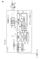
図1は、この発明の一実施形態に係わる分散情報連携システムの全体構成を示すブロック図である。この実施形態の分散情報連携システムは、医療機関や保健関連機関、運動関連施設等が運用する複数のデータサーバDSV1〜DSVnと、複数(m台)のサービス連携サーバSSV1〜SSVmと、ポータルサーバPSVと、認証サーバASVと、ユーザ登録サーバUSVを備え、これらのサーバDS1〜DSn,SSV1〜SSVm,PSV,ASV,USV相互間、及びこれらのサーバと利用者端末UTとの間で、通信網NWを介して通信可能としたものである。なお、nはデータサーバの数であり自然数(正の整数)、mはサーバ連携サーバの数であり自然数(正の整数)である。
Hereinafter, an embodiment according to the present invention will be described with reference to the drawings.
FIG. 1 is a block diagram showing the overall configuration of a distributed information cooperation system according to an embodiment of the present invention. The distributed information linkage system of this embodiment includes a plurality of data servers DSV1 to DSVn operated by medical institutions, health related organizations, exercise related facilities, etc., a plurality (m units) of service linkage servers SSV1 to SSVm, and a portal server PSV. And an authentication server ASV and a user registration server USV, and a communication network NW between these servers DS1 to DSn, SSV1 to SSVm, PSV, ASV, USV and between these servers and the user terminal UT It is possible to communicate via this. Note that n is the number of data servers and is a natural number (positive integer), and m is the number of server cooperation servers and is a natural number (positive integer).
利用者端末UTには、患者等の一般ユーザが自宅等において使用する一般ユーザ用の端末と、医師や保健師、薬剤師等が患者の依頼を受けて患者の医療データ等を取得するために使用する業務用の端末と、ユーザ登録サーバUSVに設けられるオペレータ用のコンソール端末(図示せず)が含まれる。 The user terminal UT is used for general user terminals such as patients used at home, etc., and for doctors, public health nurses, pharmacists, etc. to obtain medical data of patients at the request of patients. And an operator console terminal (not shown) provided in the user registration server USV.
通信ネットワークNWは、例えばインターネットに代表されるIP(Internet Protocol)網と、このIP網に対しアクセスするための複数のアクセス網とから構成される。アクセス網としては、例えばLAN(Local Area Network)、無線LAN、携帯電話網、有線電話網、CATV(Cable Television)網が用いられる。 The communication network NW includes, for example, an IP (Internet Protocol) network represented by the Internet and a plurality of access networks for accessing the IP network. As the access network, for example, a LAN (Local Area Network), a wireless LAN, a mobile phone network, a wired phone network, and a CATV (Cable Television) network are used.
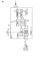
データサーバDSV1〜DSVnは、中央制御ユニット(Central Control Unit;CPU)に、バスを介してプログラムメモリ、データメモリ及び通信インタフェースを接続したもので、その機能モジュールとしてユーザ設定処理モジュール11と、データベース群12と、連携処理モジュール13と、アプリケーション処理モジュール14とを備えている。
The data servers DSV1 to DSVn are obtained by connecting a program memory, a data memory, and a communication interface to a central control unit (CPU) via a bus. As a function module thereof, a user
図2は、これらの機能モジュールの具体的な構成を示すブロック図である。データベース群12は、ID連携データベース(ID連携DB)121と、ユーザデータベース(ユーザDB)122と、開示設定データベース(開示設定DB)123と、アプリケーションデータベース(アプリケーションDB)124とを備える。ユーザDB122には、各ユーザを識別し管理するためのユーザ情報が記憶される。ユーザ情報は、ユーザID、ユーザ基本情報及びユーザ属性等からなる。アプリケーションDB124には、各ユーザの保健指導情報及び健康診断情報が上記ユーザIDに対応付けられて格納される。ID連携DB121には、ユーザ登録サーバUSVから登録を要求されたID連携情報が記憶される。このときID連携情報とは、他サーバから自サーバのあるユーザの個人データにアクセスするための情報である。開示設定DB123には、アプリケーションDB124に格納されているユーザの個人データ、つまり保健指導情報や健康診断情報について、当該情報を誰に対し開示するかを設定するための開示設定情報が記憶される。
FIG. 2 is a block diagram showing a specific configuration of these functional modules. The
ユーザ設定処理モジュール11は、ユーザ登録サーバUSVからの要求に応じて、自らのID連携DB121及びユーザDB122の検索、ID連携DB121へのID連携情報の登録又は削除、ユーザDB122へのユーザ情報の登録又は削除を行い、その結果をユーザ登録サーバUSVに応答するもので、連携基盤配布部111と、個別カスタム部112を備える。
In response to a request from the user registration server USV, the user
例えば、検索要求の場合連携基盤配布部111は、ID連携DB121を検索すると共に、必要に応じて個別カスタム部112を介してユーザDB122を検索し、その各検索結果をユーザ登録サーバUSVに応答する。個別カスタム部112は、連携基盤配布部111からの要求に応じてユーザDB122を検索し、その検索結果を連携基盤配布部111に応答する。また、登録要求の場合には、連携基盤配布部111は登録を要求されたID連携情報をID連携DB121に記憶させ、かつユーザ情報を個別カスタム部112を介してユーザDB122に記憶させる。削除要求の場合には、ID連携DB121及びユーザDB122に記憶された削除対象のID連携情報及びユーザ情報を削除する。
For example, in the case of a search request, the link
連携処理モジュール13は、認証サーバASVから認証情報を取得し、ID連携DB121を用いて他のデータサーバDSV、サービス連携サーバSSV1〜SSVm又はポータルサーバPSVとの間で属性交換(個人データの流通)を行うもので、SAML(Security Assertion Markup Language)におけるSP等の機能を有する認証連携部131と、ID−WSF(Identity Web Service Framework)におけるWSC(Web Service Consumer)等の機能を有する属性交換部132とを備える。なお、ID−WSF(Identity Web Service Framework)及びSAML(Secure Assertion Markup Language)は、Liberty Allianceが定めているWeb Serviceのための仕様である。
The
アプリケーション処理モジュール14は、ユーザDB122、開示設定DB123及びアプリケーションDB124を用いて、開示設定要求に基づく開示設定処理と、サービス連携サーバSSV1〜SSVmに対するデータ提供処理及び開示制御を行うもので、EHR用PF接続部145と、データ提供部144と、開示設定部142と、開示制御部143とを備えている。
The
EHR用PF接続部145は、アプリケーション141から上記認証連携部131もしくは属性交換部132を利用することを容易にする。データ提供部144は、認証連携部131及び属性交換部132を通じてサービス連携サーバSSV1〜SSVmからの要求を受理し、この要求に該当するデータをアプリケーションDB124から検索して、この検索データを属性交換部132を通じてサービス連携サーバSSV1〜SSVmに返送する。開示設定部142は、ユーザ登録サーバUSVもしくはサービス連携サーバSSV1〜SSVmからの要求に応じて、開示設定DB123への開示設定情報の追加、更新又は削除を行う。開示制御部143は、サービス連携サーバSSV1〜SSVmからデータ収集要求を受信したときに、個人データをサービス連携サーバSSV1〜SSVmへ送信するか否かを、開示設定DB123に記憶された開示設定情報に基づいて制御する。
The EHR
また、アプリケーション処理モジュール14は、アプリケーションDB124に格納された個人データ、つまり保健指導情報及び健康診断情報に基づいて、特定保健指導等を行うためのアプリケーション141を備える。このアプリケーション141は、EHR用PF接続部145に従って、データサーバ内の上記各機能モジュールを利用することができ、それ以外の部分は自由に作成できる。
The
ポータルサーバPSVも、CPUにバスを介してプログラムメモリ、データメモリ及び通信インタフェースを接続したもので、その機能モジュールとして、ユーザ設定処理モジュール21と、ID連携データベース(ID連携DB)22と、連携処理モジュール23と、利用者操作モジュール24を備えている。
The portal server PSV also has a program memory, a data memory, and a communication interface connected to the CPU via a bus. As its functional modules, a user
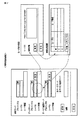
図3は、上記ポータルサーバPSVの各機能モジュールの具体的な構成を示すブロック図である。ID連携DB22には、ユーザ登録サーバUSVから登録を要求されたID連携情報が記憶される。ユーザ設定処理モジュール21は連携基盤配布部を有する。この連携基盤配布部は、ユーザ登録サーバUSVからの要求が検索要求の場合は、自らのID連携DB22を検索してその検索結果をユーザ登録サーバUSVに対し応答する。また連携基盤配布部は、ユーザ登録サーバUSVからの要求が登録要求の場合には、登録を要求されたID連携情報をID連携DB22に記憶させる。これに対しユーザ登録サーバUSVからの要求が削除要求の場合には、ID連携DB22に記憶された削除対象のID連携情報を削除する。
FIG. 3 is a block diagram showing a specific configuration of each functional module of the portal server PSV. The
連携処理モジュール23は、認証サーバASVから認証情報を取得し、ID連携DB22を用いてデータサーバDSV1〜DSVn、サービス連携サーバSSV1〜SSVm又は他のポータルサーバとの間で属性交換を行うもので、認証連携部を有する。この認証連携部は、利用者操作画面を通じて利用者のログイン要求を受けた際に、認証サーバASVの認証部に認証を要求する。利用者操作モジュール24は複数の利用者操作部241〜24Nを有する。これらの操作部はそれぞれ利用者端末UTにおけるユーザの操作を処理する。なお、Nは利用者操作部の数で、自然数(正の整数)である。
The
認証サーバASVも、CPUに対しバスを介してプログラムメモリ、データメモリ及び通信インタフェースを接続したもので、その機能モジュールとして、ユーザ設定処理モジュール31と、データベース群32と、連携処理モジュール33と、認証処理モジュール34とを備えている。
The authentication server ASV also has a program memory, a data memory, and a communication interface connected to the CPU via a bus, and as its functional modules, a user
図4は、この認証サーバASVの機能モジュールの具体的な構成を示すブロック図である。データベース群32には、ID連携データベース(ID連携DB)321と、ユーザデータベース(ユーザDB)322と、ディレクトリデータベース(ディレクトリDB)323が設けられている。ユーザDB322には、各ユーザを識別し管理するためのユーザ情報が記憶される。ID連携DB321には、ユーザ登録サーバUSVから登録を要求されたID連携情報が記憶される。このID連携情報は、それぞれのユーザに対してサーバごとに設定される。ディレクトリDB323には、個人データの所在を表すディレクトリデータが記憶される。
FIG. 4 is a block diagram showing a specific configuration of the functional module of the authentication server ASV. The
ユーザ設定処理モジュール31は、ユーザ登録サーバUSVからの要求に応じて、自らのID連携DB321及びユーザDB322の検索、ID連携DB321へのID連携情報の登録又は削除、ユーザDB322へのユーザ情報の登録又は削除を行い、その検索結果をユーザ登録サーバUSVに対し応答するもので、連携基盤配布部311及び個別カスタム部312を有する。
In response to a request from the user registration server USV, the user
例えば、検索要求の場合、連携基盤配布部311はID連携DB321を検索すると共に、必要に応じて個別カスタム部312を介してユーザ情報を検索し、これらの検索結果をユーザ登録サーバUSVに応答する。個別カスタム部312は、連携基盤配布部311からの検索要求に応じてユーザDB322を検索し、その検索結果を連携基盤配布部311に返す。また、登録要求の場合には、連携基盤配布部311は登録を要求されたID連携情報をID連携DB321に記憶させ、かつユーザ情報を個別カスタム部312を介してユーザDB322に記憶させる。削除要求の場合には、ID連携DB321及びユーザDB322に記憶された削除対象のID連携情報及びユーザ情報を削除する。
For example, in the case of a search request, the linkage
連携処理モジュール33は、ユーザDB322、ID連携DB321及びディレクトリDB323を用いてデータサーバDSV1〜DSVn、サービス連携サーバSSV1〜SSVm及びポータルサーバPSVに対し、認証情報の提供及びディレクトリサービスの提供を行うもので、属性交換部331及び認証連携部332を有している。属性交換部331は、例えばID−WSFにおけるSP(Service Provider)の機能を有するもので、ディレクトリDB323を利用してディレクトリサービスを提供する。認証連携部332は、SAMLにおけるIDP(Identity Provider)等の機能を有する。
The
認証処理モジュール34はユーザに対する認証処理を行うもので、認証部を有する。認証部は、利用者端末UTにおいてユーザが入力したユーザ情報をもとに、ユーザDB322を参照して当該ユーザの正当性を認証する。認証方式としては、ID/パスワード認証、公開鍵暗号基盤(PKI;Public Key Infrastructure)認証、又は多要素認証等が用いられる。
The
サービス連携サーバSSV1〜SSVmも、CPUにバスを介してプログラムメモリ、データメモリ及び通信インタフェースを接続したもので、その機能モジュールとして、ユーザ設定処理モジュール41と、データベース群42と、連携処理モジュール43と、アプリケーション処理モジュール44を備えている。
The service cooperation servers SSV1 to SSVm also have a CPU connected with a program memory, a data memory, and a communication interface via a bus. As the function modules, a user
図5は、このサービス連携サーバSSV1〜SSVmの機能モジュールの具体的構成を示すブロック図である。データベース群42には、ID連携データベース(ID連携DB)421と、ユーザデータベース(ユーザDB)422とが設けられている。ID連携DB421には、ユーザ登録サーバUSVから登録を要求されたID連携情報が記憶される。ユーザDB422には、各ユーザを識別し管理するためのユーザ情報が記憶される。
FIG. 5 is a block diagram showing a specific configuration of functional modules of the service cooperation servers SSV1 to SSVm. The
ユーザ設定処理モジュール41は、ユーザ登録サーバUSVからの検索要求に応じて、自らのID連携DB421及びユーザDB422の検索、ID連携DB421へのID連携情報の登録又は削除、ユーザDB422へのユーザ情報の登録又は削除を行い、その検索結果をユーザ登録サーバUSVに対し応答するもので、連携基盤配布部411と、個別カスタム部412を備える。
In response to a search request from the user registration server USV, the user
例えば、検索要求の場合連携基盤配布部411は、ID連携DB421を検索すると共に、必要に応じて個別カスタム部412を介してユーザDB422を検索し、その各検索結果をユーザ登録サーバUSVに応答する。個別カスタム部412は、連携基盤配布部411からの検索要求に応じてユーザDB422を検索し、その検索結果を連携基盤配布部411に応答する。また、登録要求の場合には、連携基盤配布部411は登録を要求されたID連携情報をID連携DB421に記憶させ、かつユーザ情報を個別カスタム部412を介してユーザDB422に記憶させる。削除要求の場合には、ID連携DB421及びユーザDB422に記憶された削除対象のID連携情報及びユーザ情報を削除する。
For example, in the case of a search request, the link
連携処理モジュール43は、認証サーバから認証情報を取得し、ID連携DB421を用いて、データサーバDSV1〜DSVn、他のサービス連携サーバSSV又はポータルサーバPSVとの間で属性交換を行うもので、認証連携部431及び属性交換432を有している。認証連携部431は、SAMLにおけるSP等の機能を有する。属性交換432は、ID−WSFにおけるWSC等の機能を有する。
The
アプリケーション処理モジュール44は、ユーザDB422を用いてデータサーバDSV1〜DSVnに対して個人データの開示設定及び個人データの収集を要求するもので、EHR用プラットフォーム接続部(EHR用PF接続部)444と、データ収集部443と、開示設定要求部442とを備えている。EHR用PF接続部444は、アプリケーション441から認証連携部431もしくは属性交換部432を利用することを容易にする。データ収集部443は、ユーザの指定に応じてデータサーバDSV1〜DSVnから収集する個人データの抽出条件を設定し、認証連携部431及び属性交換部432を通じてデータサーバDSV1〜DSVnにデータの収集要求を送信する。開示設定要求部442は、ユーザからの開示設定要求に応じて、データサーバDSV1〜DSVnに対し開示設定DBへの開示設定情報の追加、更新又は削除を要求する。
The
また、アプリケーション処理モジュール44は、個人に関する様々な医療・健康情報の一覧参照サービス等を行うためのアプリケーション441を備える。このアプリケーション441は、EHR用PF接続部444に従って、サービス連携サーバ内の上記各機能モジュールを利用することができ、それ以外の部分は自由に作成できる。
In addition, the
ユーザ登録サーバUSVも、CPUにバスを介してプログラムメモリ、データメモリ及び通信インタフェースを接続したもので、その機能モジュールとして、ユーザ設定処理モジュール51と、各ユーザのユーザ情報を記憶するためのユーザデータベース(ユーザDB)52と、利用者操作処理モジュール53とを備えている。
The user registration server USV also has a CPU connected with a program memory, a data memory and a communication interface via a bus. As a function module thereof, a user
図6は、このユーザ登録サーバUSVが備える機能モジュールの具体的な構成を示すブロック図である。ユーザ設定処理モジュール51は、ユーザ管理部511と、ID連携管理部512と、サービス関連付け管理部513と、匿名ID管理部514と、ユーザ検索部515とを有する。
FIG. 6 is a block diagram showing a specific configuration of functional modules provided in the user registration server USV. The user
ユーザ管理部511は、ユーザ(オペレータ)からの操作に応じて自らのユーザDB52を更新すると共に、認証サーバASV、データサーバDSV1〜DSVn及びサービス連携サーバSSV1〜SSVmに対してユーザ登録、更新又は削除を要求する。
ID連携管理部512は、ユーザ(オペレータ)の操作に応じて、自らがユーザDB52により管理するユーザIDと、認証サーバASV、データサーバDSV1〜DSVn及びサービス連携サーバSSV1〜SSVmがそれぞれ管理するユーザIDとの間の関連付けとその解除処理を行う。
The
The ID
サービス関連付け管理部513は、ユーザ(オペレータ)の操作に応じて、データサーバDSV1〜DSVnを利用可能/不可能にするために、認証サーバASVに対してサービス関連情報の登録/解除を要求する。
匿名ID管理部514は、ユーザ(オペレータ)の操作に応じて、認証サーバASV、データサーバDSV1〜DSVn及びサービス連携サーバSSV1〜SSVmに対し、匿名ID(SAML等)をユーザIDに、もしくはユーザIDから匿名ID(SAML等)に変換するよう要求する。
The service
The anonymous
ユーザ検索部515は、ユーザ(オペレータ)の操作に応じて自らが管理するユーザDB52を検索すると共に、認証サーバASV、データサーバDSV1〜DSVn及びサービス連携サーバSSV1〜SSVmに対し、指定された条件でユーザ検索を要求する。
利用者操作処理モジュール53はユーザによる操作を処理するもので、業務フローに応じて上記各機能部を効率的に呼び出す。
The
The user
次に、以上のように構成されたシステムによる分散情報収集動作を説明する。
(1)ユーザ情報及びその連携情報の一括登録処理
ここでは、例えば自治体の医療情報センタの職員(オペレータ)がユーザ登録サーバUSVに設けられたコンソール端末を操作して、指定した1つ以上の認証サーバASV、データサーバDSV1〜DSVn、サービス連携サーバSSV1〜SSVm又はポータルサーバPSVに対しユーザ情報の登録処理を行う場合を例にとって説明する。
Next, the distributed information collection operation by the system configured as described above will be described.
(1) Batch registration processing of user information and associated information
Here, for example, a staff member (operator) of a local government medical information center operates a console terminal provided in the user registration server USV to designate one or more specified authentication servers ASV, data servers DSV1 to DSVn, and service cooperation server SSV1. A case where user information registration processing is performed for SSVm or portal server PSV will be described as an example.
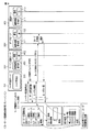
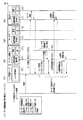
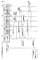
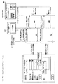
図8乃至図10は、このユーザ情報及びその連携情報の一括登録処理の手順を示すシーケンス図である。
(A) 先ず、コンソール端末において、オペレータがユーザ登録サーバUSVの所定のURL(Uniform Resource Locator)に対しアクセスすると、ユーザ登録サーバUSVからコンソール端末に対しユーザ一括登録画面がダウンロードされて表示される。図7に、表示されるユーザ一括登録画面の一例を示す。
この状態で、オペレータは、ユーザ登録を行いたいデータサーバDSV1〜DSVn、サービス連携サーバSSV1〜SSVm等を順に選択指定し、検索したいユーザ情報(ユーザID、ユーザ基本情報、ユーザ属性等)を入力する。なお、このユーザ情報の入力に際しては、ユーザ検索画面を利用することが可能である。
8 to 10 are sequence diagrams showing a procedure of batch registration processing of the user information and its cooperation information.
(A) First, in the console terminal, when an operator accesses a predetermined URL (Uniform Resource Locator) of the user registration server USV, a user batch registration screen is downloaded from the user registration server USV to the console terminal and displayed. FIG. 7 shows an example of the displayed user batch registration screen.
In this state, the operator sequentially selects and designates the data servers DSV1 to DSVn, the service cooperation servers SSV1 to SSVm and the like to be registered, and inputs user information (user ID, basic user information, user attributes, etc.) to be searched. . Note that a user search screen can be used when inputting the user information.
(B) オペレータが入力したユーザ情報を用いて、ユーザ登録サーバUSVはユーザ検索部515により、図8に示すように各データサーバDSV1〜DSVnに対して、該当するユーザ情報が既に登録されている否かの検索要求を行う。
(C) この検索の結果、データサーバDSV1〜DSVn、サービス連携サーバSSV1〜SSVmの検索結果一覧の中に、登録したいユーザのユーザ情報が既に存在した場合には、当該ユーザを選択する。これに対し存在しなかった場合には、オペレータは登録したいユーザのユーザ情報を手操作で入力する。
(B) Using the user information input by the operator, the user registration server USV has already registered the corresponding user information for each of the data servers DSV1 to DSVn as shown in FIG. Make a search request for no.
(C) As a result of this search, if the user information of the user to be registered already exists in the search result list of the data servers DSV1 to DSVn and the service cooperation servers SSV1 to SSVm, the user is selected. On the other hand, if it does not exist, the operator manually inputs the user information of the user to be registered.
(D) オペレータは、登録対象のすべてのデータサーバDSV1〜DSVnに対し、上記(A) 〜(C) の処理を繰り返し行い、全ての操作が終了した後に一括登録を要求する。この一括登録の要求は、図9に示すようにコンソール端末からユーザ登録サーバUSVに送られる。 (D) The operator repeats the processes (A) to (C) for all the data servers DSV1 to DSVn to be registered, and requests batch registration after all operations are completed. This batch registration request is sent from the console terminal to the user registration server USV as shown in FIG.
(E) コンソール端末から上記一括登録要求が送られると、ユーザ登録サーバUSVはユーザ管理部511により、認証サーバASVに対して図9に示すようにユーザ登録を要求する。この要求に対し認証サーバASVは、連携基盤配布部311及び個別カスタム部312により、ID連携情報及びユーザ情報を検索し、自らが保持しているユーザIDをユーザ登録サーバUSVに返送する。
(E) When the collective registration request is sent from the console terminal, the user registration server USV requests the user registration to the authentication server ASV by the
(F) ユーザ登録サーバUSVは、上記認証サーバASVから返送されたユーザIDを使用して、ID連携管理部512により認証サーバASVに対してID連携情報の登録を要求する。この要求に対し認証サーバASVは、匿名IDを発行してユーザ登録サーバUSVに返送する。
(F) The user registration server USV uses the user ID returned from the authentication server ASV to request the authentication server ASV to register ID linkage information using the ID
(G) ユーザ登録サーバUSVは、次にユーザ管理部511により、図9に示すようにサービス連携サーバSSV1〜SSVmの1つに対してユーザ登録を要求する。この要求に対しサービス連携サーバSSV1〜SSVmは、連携基盤配布部411及び個別カスタム部412により、ID連携情報及びユーザ情報を検索し、自らが保持しているユーザIDをユーザ登録サーバUSVに返送する。
(G) Next, the user registration server USV requests user registration to one of the service cooperation servers SSV1 to SSVm as shown in FIG. In response to this request, the service cooperation servers SSV1 to SSVm search the ID cooperation information and the user information by the cooperation
(H) ユーザ登録サーバUSVは、ID連携管理部512により、上記サービス連携サーバSSV1〜SSVmから返送されたユーザIDと、上記(1-6) において認証サーバASVから取得した匿名IDを使用して、サービス連携サーバSSV1〜SSVmに対してID連携情報の登録を要求する。この要求に対しサービス連携サーバSSV1〜SSVmは、ID連携情報をID連携DB421に格納する。
(I) ユーザ登録サーバUSVは、上記(G) 及び(H) の処理をサービス連携サーバSSV1〜SSVmの数分だけ繰り返す。
(H) The user registration server USV uses the user ID returned from the service cooperation server SSV1 to SSVm by the ID
(I) The user registration server USV repeats the processes (G) and (H) for the number of service cooperation servers SSV1 to SSVm.
(J) ユーザ登録サーバUSVは、次にユーザ管理部511により、登録対象のユーザ情報がデータサーバDSV1〜DSVnに未登録の場合、図10に示すようにデータサーバDSV1〜DSVnの1つに対してユーザ登録を要求する。この要求に対しデータサーバDSV1〜DSVnは、連携基盤配布部111及び個別カスタム部112により、ID連携情報及びユーザ情報を検索し、自らが保持しているユーザIDをユーザ登録サーバUSVに返送する。
(J) Next, when the user information to be registered is not registered in the data servers DSV1 to DSVn by the
(K) またユーザ登録サーバUSVは、上記(E) により認証サーバASVから返送されたユーザIDを使用して、ID連携管理部512により認証サーバASVに対してID連携情報の登録を要求する。この要求に対し認証サーバASVは、匿名IDを発行してユーザ登録サーバUSVに返送する。
(K) Further, the user registration server USV requests the ID server ASV to register the ID link information by the
(L) ユーザ登録サーバUSVは、次にID連携管理部512により、上記(J)によりデータサーバDSV1〜DSVnから返送されたユーザIDと、上記(K) において認証サーバASVから取得した匿名IDを使用して、データサーバDSV1〜DSVnに対してID連携情報の登録を要求する。この要求に対しデータサーバDSV1〜DSVnは、ID連携情報をID連携DB121に格納する。
(L) Next, the user registration server USV receives the user ID returned from the data servers DSV1 to DSVn by (J) and the anonymous ID acquired from the authentication server ASV in (K) by the ID
(M) またそれと共にユーザ登録サーバUSVは、上記(1-5) により認証サーバASVから返送されたユーザIDを使用して、サービス関連付け管理部513により、図10に示すように認証サーバASVに対しデータサーバDSV1〜DSVnのサービス関連付けを要求する。データサーバDSV1〜DSVnは、この要求を受けると上記サービスの関連付けに関する情報を保存する。
(N) ユーザ登録サーバUSVは、上記(K) 〜(M)の処理を、データサーバDSV1〜DSVnの数分だけ繰り返す。
(O) 以上の処理が終了すると、ユーザ登録サーバUSVはユーザ登録結果を表す情報を、図10に示すように登録要求元のコンソール端末に送信する。
(M) At the same time, the user registration server USV uses the user ID returned from the authentication server ASV according to (1-5) above to the authentication server ASV by the service
(N) The user registration server USV repeats the processes (K) to (M) as many times as the number of data servers DSV1 to DSVn.
(O) When the above processing is completed, the user registration server USV transmits information indicating the user registration result to the console terminal of the registration request source as shown in FIG.
(2)ユーザID/匿名IDの問い合わせ処理
ユーザIDをもとにサーバ間の連携に使用している匿名IDを問い合わせる処理と、反対に匿名IDをもとにユーザIDを問い合わせる処理について、その手順を説明する。この処理機能を組み合わせることで、サーバ間のユーザIDの変換が可能となる。
図11は、このユーザID/匿名IDの問い合わせ処理の手順を示すシーケンス図である。
(2) User ID / anonymous ID inquiry process The process of inquiring about the anonymous ID used for cooperation between servers based on the user ID and the process of inquiring the user ID based on the anonymous ID Will be explained. By combining these processing functions, it is possible to convert user IDs between servers.
FIG. 11 is a sequence diagram showing the procedure of the user ID / anonymous ID inquiry process.
(2−1)ユーザIDから匿名IDの問い合わせ
(A) コンソール端末においてオペレータは、図11に例示するようにユーザID/匿名ID問い合わせ画面が表示されている状態で、問い合わせ対象のサーバ(認証サーバASV、データサーバDSV1〜DSVn、サービス連携サーバSSV1〜SSVn、ポータルサーバPSV)と、ユーザID及び連携先のサーバ(認証サーバASV、データサーバDSV1〜DSVn、サービス連携サーバSSV1〜SSVn、ポータルサーバPSV)をそれぞれ指定する。
(2-1) Inquiry of anonymous ID from user ID
(A) In the console terminal, the operator displays an inquiry target server (authentication server ASV, data servers DSV1 to DSVn, service cooperation server SSV1) while the user ID / anonymous ID inquiry screen is displayed as illustrated in FIG. To SSVn, portal server PSV), and a user ID and a cooperation destination server (authentication server ASV, data servers DSV1 to DSVn, service cooperation servers SSV1 to SSVn, portal server PSV), respectively.
(B) これに対しユーザ登録サーバUSVは、オペレータが指定した上記各サーバの連携基盤配布部111,311,411に対して、ユーザID/匿名IDの変換処理要求を送信する。なお、ユーザ登録サーバUSVにプロキシサーバの設定がある場合は、プロキシサーバPSV経由で要求を送信する。
(B) On the other hand, the user registration server USV transmits a user ID / anonymous ID conversion processing request to the cooperation
(C) 上記ユーザ登録サーバUSVからの要求を受信すると、各サーバの連携基盤配布部111,311,411は、ID連携DB121,321,421を参照し、ユーザIDをキーとして対応する匿名IDを読み出し、この読み出した匿名IDをユーザ登録サーバUSVへ返送する。
(C) Upon receiving a request from the user registration server USV, the link
(D) ユーザ登録サーバUSVは、サーバの連携基盤配布部111,311,411から、上記要求したユーザID/匿名IDの変換処理要求に対する変換結果を受信する。
(E) ユーザ登録サーバUSVは、上記受信したユーザIDから匿名IDへの変換結果をコンソール端末に送信し、表示させる。
(D) The user registration server USV receives a conversion result for the requested user ID / anonymous ID conversion processing request from the cooperation
(E) The user registration server USV transmits the conversion result from the received user ID to the anonymous ID to the console terminal for display.
(2−2)匿名IDからユーザIDへの問い合わせ
(A) コンソール端末においてオペレータは、図11に例示するようにユーザID/匿名ID問い合わせ画面が表示されている状態で、問い合わせ対象のサーバ(認証サーバASV、データサーバDSV1〜DSVn、サービス連携サーバSSV1〜SSVn、ポータルサーバPSV)と、ユーザID及び連携先のサーバ(認証サーバASV、データサーバDSV1〜DSVn、サービス連携サーバSSV1〜SSVn、ポータルサーバPSV)をそれぞれ指定する。
(2-2) Inquiry from anonymous ID to user ID
(A) In the console terminal, the operator displays an inquiry target server (authentication server ASV, data servers DSV1 to DSVn, service cooperation server SSV1) while the user ID / anonymous ID inquiry screen is displayed as illustrated in FIG. To SSVn, portal server PSV), and a user ID and a cooperation destination server (authentication server ASV, data servers DSV1 to DSVn, service cooperation servers SSV1 to SSVn, portal server PSV), respectively.
(B) これに対しユーザ登録サーバUSVは、オペレータが指定した上記各サーバの連携基盤配布部111,311,411に対して、匿名ID/ユーザIDの変換処理要求を送信する。なお、ユーザ登録サーバUSVにプロキシサーバの設定がある場合は、プロキシサーバPSV経由で要求を送信する。
(B) On the other hand, the user registration server USV transmits an anonymous ID / user ID conversion processing request to the cooperation
(C) 上記ユーザ登録サーバUSVからの要求を受信すると、各サーバの連携基盤配布部111,311,411は、ID連携DB121,321,421を参照し、匿名IDをキーとして対応するユーザIDを読み出し、この読み出したユーザIDをユーザ登録サーバUSVへ返送する。
(C) Upon receiving the request from the user registration server USV, the link
(D) ユーザ登録サーバUSVは、サーバの連携基盤配布部111,311,411から、上記要求した匿名ID/ユーザIDの変換処理要求に対する変換結果を受信する。
(E) ユーザ登録サーバUSVは、上記受信した匿名IDからユーザIDへの変換結果をコンソール端末に送信し、表示させる。
(D) The user registration server USV receives the conversion result for the requested anonymous ID / user ID conversion processing request from the cooperation
(E) The user registration server USV transmits the conversion result from the received anonymous ID to the user ID to the console terminal and displays it.
(3)ユーザ登録と同時に開示設定を行う処理
図12は、このユーザ登録と同時に開示設定を行う処理のシーケンスを示す図である。
ユーザ登録サーバUSVから、認証サーバASV、データサーバDSV1〜DSVn、サービス連携サーバSSV1〜SSVn及びポータルサーバPSVへ送信する要求の中で、付加情報を「キー=値」の組み合わせで汎用的に保持可能な形態にする。
(3) Process for Performing Disclosure Setting Simultaneously with User Registration FIG. 12 is a diagram showing a sequence of a process for performing disclosure setting simultaneously with this user registration.
Additional information can be held for general use with a combination of “key = value” in the request sent from the user registration server USV to the authentication server ASV, the data servers DSV1 to DSVn, the service cooperation servers SSV1 to SSVn, and the portal server PSV. Form.
先に(1)において説明したユーザ情報及びその連携情報の一括登録処理の手順に、以下の手順を追加する。
先ず該当ユーザがデータサーバDSV1〜DSVnに登録されたユーザだった場合には、ユーザ登録サーバUSVからサービス連携サーバSSV1〜SSVnに対して、該当ユーザの開示設定情報の提供を要求し、その結果をコンソール端末に送信する。コンソール端末においてオペレータは、該当ユーザに対する追加開示設定情報を入力する。ユーザ登録サーバUSVは、データサーバDSV1〜DSVnに対してユーザ登録要求を行う際に、付加情報として「開示設定情報=add:userA」を要求に埋め込む。
The following procedure is added to the procedure for batch registration processing of user information and associated information described in (1) above.
First, when the corresponding user is a user registered in the data servers DSV1 to DSVn, the user registration server USV requests the service cooperation servers SSV1 to SSVn to provide the disclosure setting information of the corresponding user, and the result is displayed. Send to console terminal. In the console terminal, the operator inputs additional disclosure setting information for the user. When the user registration server USV makes a user registration request to the data servers DSV1 to DSVn, “disclosure setting information = add: userA” is embedded in the request as additional information.
データサーバDSV1〜DSVnは、ユーザ登録サーバUSVからユーザ登録、更新又は削除の要求を受信すると、当該要求に埋め込まれている付加情報に開示設定情報が含まれているか判定する。そして、付加情報に上記ユーザ属性が含まれていた場合には、この情報に基づいて、自らの開示設定DB123に対し開示設定情報を追加、更新又は削除する処理を行う。
When the data servers DSV1 to DSVn receive a request for user registration, update, or deletion from the user registration server USV, the data servers DSV1 to DSVn determine whether or not the disclosure setting information is included in the additional information embedded in the request. If the user attribute is included in the additional information, based on this information, a process for adding, updating, or deleting the disclosure setting information to its own
なお、以上(1)〜(3)で述べたユーザ登録処理、ID変換処理及び開示設定処理は、いずれも通信ネットワークNW上において、サービス連携サーバSSV1〜SSVnがデータサーバDSV1〜DSVnから個人データを収集して利用者端末UTに配信するために使用される通信チャネルとは異なる、登録・設定専用の通信チャネルを介して行われる。 The user registration process, the ID conversion process, and the disclosure setting process described in (1) to (3) are all performed by the service cooperation servers SSV1 to SSVn from the data servers DSV1 to DSVn on the communication network NW. This is performed via a communication channel dedicated for registration and setting, which is different from the communication channel used for collecting and distributing to the user terminal UT.
以上述べたようにこの実施形態では、ユーザ登録サーバUSVにおいて、利用者端末UTからユーザ一括登録要求が送られた場合に、上記認証サーバASVと協働して他の各サーバが保有するユーザID間を連携するためのID連携情報を生成し、この生成されたID連携情報を上記データサーバDSV1〜DSVn及びサービス連携サーバSSV1〜SSVnにそれぞれ送信して登録するようにしている。 As described above, in this embodiment, in the user registration server USV, when a user batch registration request is sent from the user terminal UT, user IDs held by other servers in cooperation with the authentication server ASV. ID linkage information for linking each other is generated, and the generated ID linkage information is transmitted and registered to the data servers DSV1 to DSVn and the service linkage servers SSV1 to SSVn, respectively.
したがって、各サーバにそれぞれ登録されたユーザID間を連携させるためのID連携情報と、認証サーバASVが管理するユーザの認証情報とに基づいて、サービス連携サーバSSV1〜SSVnにより各データサーバDSV1〜DSVnからユーザの個人データが収集され、この収集された個人データが要求元の利用者端末UTに配信される。このため、ユーザはリアルタイムに自身に係わる個人データを取得することができる。また、要求に応じてその都度各データサーバから個人データが収集されるので、個人データを集中管理するためのデータベースが不要となる。このため、分散情報の連携配信サービスを提供しようとする際の設備上及び管理上の負担が軽減され、さらに利用者数の増加や医療データを管理しているデータサーバ数の増加要求にも対応し易くなり、これによりスケーラビリティのあるシステムを提供可能となる。 Therefore, based on the ID linkage information for linking user IDs registered in each server and the user authentication information managed by the authentication server ASV, the service linkage servers SSV1 to SSVn perform the data servers DSV1 to DSVn. The personal data of the user is collected from this, and the collected personal data is distributed to the requesting user terminal UT. For this reason, the user can acquire personal data relating to the user in real time. In addition, since personal data is collected from each data server each time it is requested, a database for centrally managing personal data becomes unnecessary. This reduces the burden on facilities and management when trying to provide a distributed distribution service, and responds to requests for an increase in the number of users and the number of data servers managing medical data. This makes it possible to provide a scalable system.
しかも、ユーザ登録サーバUSVにより、すべてのサーバに対しユーザの情報間を連携させるためのID連携情報が一括して登録される。このため、きわめて効率良くID連携情報の登録を行うことができ、かつ不慣れなユーザやオペレータであっても誤ることなく登録を行うことができる。 In addition, the ID registration information for linking user information to all servers is collectively registered by the user registration server USV. For this reason, ID linkage information can be registered very efficiently, and even an unfamiliar user or operator can register without error.
さらに、この実施形態では、各データサーバDSV1〜DSVnに対する個人データの開示設定処理が、ユーザ一括登録処理と同時に行われる。このため、開示設定処理をユーザ一括登録処理とは別々に行う場合に比べ、開示設定の処理を効率良く行うことができる。 Furthermore, in this embodiment, the disclosure setting process of personal data for each of the data servers DSV1 to DSVn is performed simultaneously with the user batch registration process. For this reason, the disclosure setting process can be performed more efficiently than when the disclosure setting process is performed separately from the user batch registration process.
なお、この発明は上記実施形態に限定されるものではない。例えば、ポータルサーバPSVは設けても設けなくてもよく、またサービス連携サーバは複数台であっても1台であってもよい。その他、ユーザ登録サーバ、データサーバ、サービス連携サーバ及び認証サーバの構成、ユーザ一括登録処理の手順とその内容、開示設定処理の手順とその内容等についても、この発明の要旨を逸脱しない範囲で種々変形して実施できる。 The present invention is not limited to the above embodiment. For example, the portal server PSV may or may not be provided, and the service cooperation server may be a plurality or one. In addition, the configuration of the user registration server, data server, service cooperation server, and authentication server, the procedure and contents of the user batch registration process, the procedure and contents of the disclosure setting process, and the like can be variously within the scope of the present invention. It can be implemented with deformation.
要するにこの発明は、上記実施形態そのままに限定されるものではなく、実施段階ではその要旨を逸脱しない範囲で構成要素を変形して具体化できる。また、上記実施形態に開示されている複数の構成要素の適宜な組み合せにより種々の発明を形成できる。例えば、実施形態に示される全構成要素から幾つかの構成要素を削除してもよい。さらに、異なる実施形態に亘る構成要素を適宜組み合せてもよい。 In short, the present invention is not limited to the above-described embodiment as it is, and can be embodied by modifying the constituent elements without departing from the scope of the invention in the implementation stage. Further, various inventions can be formed by appropriately combining a plurality of constituent elements disclosed in the embodiment. For example, some components may be deleted from all the components shown in the embodiment. Furthermore, you may combine suitably the component covering different embodiment.
DSV1〜DSVn…データサーバ、PSV…ポータルサーバ、ASV…認証サーバ、SSV1〜SSVm…サービス連携サーバ、USV…ユーザ登録サーバUSV、UT…利用者端末、NW…通信網、11,21,31,41,51…ユーザ設定モジュール、12,22,32,42,52…データベース群、13,23,33,43…連携処理モジュール、14,44…アプリケーション処理モジュール、24,53…利用者操作処理モジュール、34…認証処理モジュール、111,211,311,411…連携基盤配布部、112,312,412…個別カスタム部、121,22,321,421…ID連携データベース、122,322,422,52…ユーザデータベース、123…開示設定データベース、124…アプリケーションデータベース、323…ディレクトリデータベース、131,231,332,431…認証連携部、132,331,432…属性交換部、141,441…アプリケーション、142…開示設定部、143…開示制御部、144…データ提供部、241〜24n…利用者操作部、341…認証部、442…開示設定要求部、443…データ収集部、444…EHR用PF接続部、511…ユーザ管理部、512…ID連携管理部、513…サービス関連付け管理部、514…匿名ID管理部、515…ユーザ検索部。 DSV1 to DSVn ... data server, PSV ... portal server, ASV ... authentication server, SSV1-SSVm ... service cooperation server, USV ... user registration server USV, UT ... user terminal, NW ... communication network, 11, 21, 31, 41 , 51 ... User setting module, 12, 22, 32, 42, 52 ... Database group, 13, 23, 33, 43 ... Cooperation processing module, 14, 44 ... Application processing module, 24, 53 ... User operation processing module, 34 ... Authentication processing module, 111, 211, 311, 411 ... Cooperation infrastructure distribution part, 112, 312, 412 ... Individual custom part, 121, 22, 321, 421 ... ID cooperation database, 122, 322, 422, 52 ... User Database, 123 ... Disclosure setting database, 124 ... Application ,..., Directory database, 131, 231, 332, 431, authentication cooperation unit, 132, 331, 432, attribute exchange unit, 141, 441, application, 142, disclosure setting unit, 143, disclosure control unit, 144 ... Data providing unit, 241 to 24n ... User operation unit, 341 ... Authentication unit, 442 ... Disclosure setting request unit, 443 ... Data collection unit, 444 ... EHR PF connection unit, 511 ... User management unit, 512 ... ID linkage Management unit, 513... Service association management unit, 514... Anonymous ID management unit, 515.
Claims (11)
少なくとも前記複数のデータサーバ、サービス連携サーバ及び認証サーバに対し前記通信ネットワークを介して接続可能なユーザ登録サーバをさらに具備し、
このユーザ登録サーバは、前記利用者端末から発せられるユーザ一括登録要求に応じ、前記認証サーバと協働して連携情報を生成し、この連携情報を前記通信ネットワークを介して前記複数のデータサーバ、サービス連携サーバ及び認証サーバにそれぞれ送信し登録させる連携管理手段を、備えることを特徴とする分散情報連携システム。 A plurality of data servers that manage personal data for each user, a service cooperation server, an authentication server, and a user terminal can be connected via a communication network, and in response to an information acquisition request from the user terminal Based on the cooperation information for linking user information each managed by the plurality of data servers, the service cooperation server and the authentication server, and the user authentication information managed by the authentication server, the service cooperation server A distributed information cooperation system that collects personal data of the user from the plurality of data servers, and distributes the collected personal data to the requesting user terminal via the communication network,
A user registration server connectable to at least the plurality of data servers, service cooperation server and authentication server via the communication network;
In response to a user batch registration request issued from the user terminal, the user registration server generates cooperation information in cooperation with the authentication server, and the cooperation information is transmitted to the plurality of data servers via the communication network. What is claimed is: 1. A distributed information linkage system comprising linkage management means for transmitting and registering to a service linkage server and an authentication server, respectively.
前記利用者端末からのユーザ一括登録要求に応じて、複数のデータサーバ、サービス連携サーバ及び認証サーバに対し、当該要求元のユーザに係わる連携情報が登録済みか否かを前記通信ネットワークを介して問い合わせる手段と、
前記問い合わせの結果、要求元のユーザに係わる連携情報が未登録と判定された場合に、前記認証サーバに対し連携情報の生成を要求して生成された連携情報を取得し、この取得した連携情報を前記通信ネットワークを介して前記未登録のデータサーバ、サービス連携サーバ及び認証サーバに送信して登録させる手段と
を備えることを特徴とする請求項1記載の分散情報連携システム。 The linkage management means includes
In response to a user batch registration request from the user terminal, whether or not cooperation information related to the requesting user has been registered for a plurality of data servers, service cooperation servers and authentication servers via the communication network. Means to contact,
As a result of the inquiry, when it is determined that the cooperation information related to the requesting user is unregistered, the authentication information is generated by requesting the authentication server to generate the cooperation information. 2. The distributed information cooperation system according to claim 1, further comprising: means for transmitting and registering to the unregistered data server, service cooperation server, and authentication server via the communication network.
前記利用者端末から送られる開示設定要求に応じて、この要求に含まれる個人データの開示の許否を指定するための開示設定情報を前記連携情報と共に前記通信ネットワークを介して該当するデータサーバに送信し設定させる手段を、さらに備えることを特徴とする請求項1記載の分散情報連携システム。 The user registration server
In response to a disclosure setting request sent from the user terminal, the disclosure setting information for designating whether or not to disclose personal data included in the request is transmitted to the corresponding data server via the communication network together with the linkage information. The distributed information cooperation system according to claim 1, further comprising means for setting and setting.
前記利用者端末からユーザ登録サーバにユーザ一括登録要求を送信する過程と、
前記送られたユーザ一括登録要求に応じて、前記ユーザ登録サーバが前記認証サーバと協働して連携情報を生成し、この生成された連携情報を前記通信ネットワークを介して前記複数のデータサーバ、サービス連携サーバ及び認証サーバにそれぞれ送信し登録させる過程と
を備えることを特徴とする分散情報連携方法。 A plurality of data servers that manage personal data for each user, a service cooperation server, an authentication server, and a user terminal can be connected via a communication network, and in response to an information acquisition request from the user terminal Based on the cooperation information for linking user information each managed by the plurality of data servers, the service cooperation server and the authentication server, and the user authentication information managed by the authentication server, the service cooperation server A distributed information linkage method used in a distributed information linkage system that collects personal data of the user from the plurality of data servers and distributes the collected personal data to the requesting user terminal via the communication network. There,
Sending a user batch registration request from the user terminal to a user registration server;
In response to the sent user batch registration request, the user registration server generates cooperation information in cooperation with the authentication server, and the generated cooperation information is sent to the plurality of data servers via the communication network, And a process for transmitting and registering to a service cooperation server and an authentication server, respectively.
前記利用者端末から送られたユーザ一括登録要求に応じて、前記ユーザ登録サーバが前記複数のデータサーバ、サービス連携サーバ及び認証サーバに対し、当該要求元のユーザに係わる連携情報が登録済みか否かを前記通信ネットワークを介して問い合わせる過程と、
前記問い合わせの結果、要求元のユーザに係わる連携情報が未登録と判定された場合に、前記ユーザ登録サーバが前記認証サーバに対し連携情報の生成を要求し、生成された連携情報を認証サーバから取得する過程と、
前記取得された連携情報を、前記ユーザ登録サーバが前記通信ネットワークを介して前記未登録のデータサーバ、サービス連携サーバ及び認証サーバへ送信して登録させる過程と
を備えることを特徴とする請求項7記載の分散情報連携方法。 The process of registering the cooperation information includes:
In response to the user batch registration request sent from the user terminal, whether or not the user registration server has registered the cooperation information related to the requesting user with the plurality of data servers, service cooperation server and authentication server. A process of inquiring through the communication network,
As a result of the inquiry, when it is determined that the cooperation information related to the requesting user is unregistered, the user registration server requests the authentication server to generate cooperation information, and the generated cooperation information is sent from the authentication server. The process of acquiring,
8. The process of transmitting and registering the acquired cooperation information to the unregistered data server, service cooperation server and authentication server via the communication network by the user registration server. The distributed information linkage method described.
前記ユーザ登録サーバが、前記送られた開示設定要求に含まれる個人データの開示の許否を指定するための開示設定情報を、前記連携情報と共に前記通信ネットワークを介して該当するデータサーバに送信し設定させる過程と
を、さらに具備することを特徴とする請求項7記載の分散情報連携方法。 A process of transmitting a disclosure setting request from the user terminal to the user registration server;
The user registration server sends and sets disclosure setting information for designating whether or not to disclose personal data included in the sent disclosure setting request to the corresponding data server via the communication network together with the linkage information. The distributed information cooperation method according to claim 7, further comprising the step of:
Priority Applications (1)
| Application Number | Priority Date | Filing Date | Title |
|---|---|---|---|
| JP2008251815A JP4848407B2 (en) | 2008-09-29 | 2008-09-29 | Distributed information linkage system and distributed information linkage method |
Applications Claiming Priority (1)
| Application Number | Priority Date | Filing Date | Title |
|---|---|---|---|
| JP2008251815A JP4848407B2 (en) | 2008-09-29 | 2008-09-29 | Distributed information linkage system and distributed information linkage method |
Publications (2)
| Publication Number | Publication Date |
|---|---|
| JP2010086080A true JP2010086080A (en) | 2010-04-15 |
| JP4848407B2 JP4848407B2 (en) | 2011-12-28 |
Family
ID=42250019
Family Applications (1)
| Application Number | Title | Priority Date | Filing Date |
|---|---|---|---|
| JP2008251815A Active JP4848407B2 (en) | 2008-09-29 | 2008-09-29 | Distributed information linkage system and distributed information linkage method |
Country Status (1)
| Country | Link |
|---|---|
| JP (1) | JP4848407B2 (en) |
Cited By (9)
| Publication number | Priority date | Publication date | Assignee | Title |
|---|---|---|---|---|
| JP2013114598A (en) * | 2011-11-30 | 2013-06-10 | Nippon Telegr & Teleph Corp <Ntt> | Information circulation system and access control method thereof |
| JP2014164650A (en) * | 2013-02-27 | 2014-09-08 | Nippon Telegr & Teleph Corp <Ntt> | Related information registration method, related information registration program, network system, cooperation data acceptance server, service cooperation server and provision side server |
| JP2015001934A (en) * | 2013-06-18 | 2015-01-05 | 日本電信電話株式会社 | Access control information management system and server device therefor and method and program |
| JP2018513478A (en) * | 2015-05-28 | 2018-05-24 | グーグル エルエルシー | Control access to data resources |
| JP2018533119A (en) * | 2015-09-07 | 2018-11-08 | インペコ ホールディング リミテッドInpeco Holding Ltd. | Patient medical record management system and method for automatically collecting clinical data |
| CN110692070A (en) * | 2016-12-21 | 2020-01-14 | 奥恩全球运营有限公司, 新加坡分公司 | System and method for automated batch user registration across both content management systems and any software applications embedded therein |
| WO2020159104A1 (en) * | 2019-02-01 | 2020-08-06 | 삼성전자 주식회사 | Electronic device for managing personal information and method therefor |
| JP2020526848A (en) * | 2017-07-14 | 2020-08-31 | ノートンライフロック インコーポレイテッド | User-driven identity verification over the network |
| JPWO2019188282A1 (en) * | 2018-03-28 | 2021-02-18 | パイオニア株式会社 | Server equipment, information processing methods, programs and storage media |
Families Citing this family (2)
| Publication number | Priority date | Publication date | Assignee | Title |
|---|---|---|---|---|
| JP5521024B1 (en) * | 2012-12-05 | 2014-06-11 | 日本電信電話株式会社 | Distributed information linkage system and method |
| JP6111186B2 (en) * | 2013-12-03 | 2017-04-05 | 日本電信電話株式会社 | Distributed information linkage system and data operation method and program thereof |
Citations (3)
| Publication number | Priority date | Publication date | Assignee | Title |
|---|---|---|---|---|
| JP2006244418A (en) * | 2005-03-07 | 2006-09-14 | Nippon Telegr & Teleph Corp <Ntt> | Service providing system and service providing device |
| JP2007299303A (en) * | 2006-05-02 | 2007-11-15 | Ntt Resonant Inc | Id cooperative authentication system and id cooperative authentication method |
| JP2008186338A (en) * | 2007-01-31 | 2008-08-14 | Nippon Telegr & Teleph Corp <Ntt> | Account linking system, account linking method, link server device, client device |
-
2008
- 2008-09-29 JP JP2008251815A patent/JP4848407B2/en active Active
Patent Citations (3)
| Publication number | Priority date | Publication date | Assignee | Title |
|---|---|---|---|---|
| JP2006244418A (en) * | 2005-03-07 | 2006-09-14 | Nippon Telegr & Teleph Corp <Ntt> | Service providing system and service providing device |
| JP2007299303A (en) * | 2006-05-02 | 2007-11-15 | Ntt Resonant Inc | Id cooperative authentication system and id cooperative authentication method |
| JP2008186338A (en) * | 2007-01-31 | 2008-08-14 | Nippon Telegr & Teleph Corp <Ntt> | Account linking system, account linking method, link server device, client device |
Cited By (12)
| Publication number | Priority date | Publication date | Assignee | Title |
|---|---|---|---|---|
| JP2013114598A (en) * | 2011-11-30 | 2013-06-10 | Nippon Telegr & Teleph Corp <Ntt> | Information circulation system and access control method thereof |
| JP2014164650A (en) * | 2013-02-27 | 2014-09-08 | Nippon Telegr & Teleph Corp <Ntt> | Related information registration method, related information registration program, network system, cooperation data acceptance server, service cooperation server and provision side server |
| JP2015001934A (en) * | 2013-06-18 | 2015-01-05 | 日本電信電話株式会社 | Access control information management system and server device therefor and method and program |
| JP2018513478A (en) * | 2015-05-28 | 2018-05-24 | グーグル エルエルシー | Control access to data resources |
| US10326768B2 (en) | 2015-05-28 | 2019-06-18 | Google Llc | Access control for enterprise knowledge |
| US10798098B2 (en) | 2015-05-28 | 2020-10-06 | Google Llc | Access control for enterprise knowledge |
| JP2018533119A (en) * | 2015-09-07 | 2018-11-08 | インペコ ホールディング リミテッドInpeco Holding Ltd. | Patient medical record management system and method for automatically collecting clinical data |
| CN110692070A (en) * | 2016-12-21 | 2020-01-14 | 奥恩全球运营有限公司, 新加坡分公司 | System and method for automated batch user registration across both content management systems and any software applications embedded therein |
| CN110692070B (en) * | 2016-12-21 | 2024-02-09 | 奥恩全球运营有限公司, 新加坡分公司 | System and method for automated batch user registration across both content management systems and any software applications embedded therein |
| JP2020526848A (en) * | 2017-07-14 | 2020-08-31 | ノートンライフロック インコーポレイテッド | User-driven identity verification over the network |
| JPWO2019188282A1 (en) * | 2018-03-28 | 2021-02-18 | パイオニア株式会社 | Server equipment, information processing methods, programs and storage media |
| WO2020159104A1 (en) * | 2019-02-01 | 2020-08-06 | 삼성전자 주식회사 | Electronic device for managing personal information and method therefor |
Also Published As
| Publication number | Publication date |
|---|---|
| JP4848407B2 (en) | 2011-12-28 |
Similar Documents
| Publication | Publication Date | Title |
|---|---|---|
| JP4848407B2 (en) | Distributed information linkage system and distributed information linkage method | |
| JP5669250B2 (en) | Information access control system, server device and information access control method | |
| JP4932861B2 (en) | Distributed information access system, distributed information access method and program | |
| US11977659B2 (en) | Data anonymization for service subscriber's privacy | |
| CN110472428A (en) | Medical data sharing method and shared system based on block chain | |
| KR100580661B1 (en) | System and Method for Unified Management of Medical Information | |
| JP4871991B2 (en) | Information access control system and server device thereof, information access control method, access control rule setting control method | |
| US20090144811A1 (en) | Content delivery system | |
| JP2011107779A (en) | Information access control system and method | |
| JP5817728B2 (en) | Condition matching system, condition matching link device, and condition matching processing method | |
| JP2016148999A (en) | Medical support system, and its operation method, medical support program and medical support device | |
| JP2004030128A (en) | Health care information sharing system, health care information sharing method, and health care information sharing program | |
| JP2009181334A (en) | Information management proxy device, service providing system, and service providing method | |
| JP6652267B1 (en) | Telemedicine support device, system, method and program | |
| JP7456041B2 (en) | Telemedicine support device, method and program | |
| JP2010157019A (en) | Medical image processing system and server device | |
| CN111048187A (en) | Family doctor signing service system | |
| JP6069111B2 (en) | Access control information management system and server device, method and program thereof | |
| KR20010096158A (en) | A system and a method for health informaton using network | |
| JP5460681B2 (en) | Information distribution system and its access control method | |
| US7213016B1 (en) | System and method for managing advance directives | |
| KR101084205B1 (en) | Method for administering an information of user on network | |
| JP2003316923A (en) | Questionnaire system and questionnaire method | |
| KR20200063722A (en) | Method for providing hospital information | |
| WO2023276826A1 (en) | Routing device, management center device, user authentication method, and user authentication program |
Legal Events
| Date | Code | Title | Description |
|---|---|---|---|
| A131 | Notification of reasons for refusal |
Free format text: JAPANESE INTERMEDIATE CODE: A131 Effective date: 20110726 |
|
| A521 | Written amendment |
Free format text: JAPANESE INTERMEDIATE CODE: A523 Effective date: 20110914 |
|
| TRDD | Decision of grant or rejection written | ||
| A01 | Written decision to grant a patent or to grant a registration (utility model) |
Free format text: JAPANESE INTERMEDIATE CODE: A01 Effective date: 20111004 |
|
| A01 | Written decision to grant a patent or to grant a registration (utility model) |
Free format text: JAPANESE INTERMEDIATE CODE: A01 |
|
| A61 | First payment of annual fees (during grant procedure) |
Free format text: JAPANESE INTERMEDIATE CODE: A61 Effective date: 20111017 |
|
| FPAY | Renewal fee payment (event date is renewal date of database) |
Free format text: PAYMENT UNTIL: 20141021 Year of fee payment: 3 |
|
| R150 | Certificate of patent or registration of utility model |
Ref document number: 4848407 Country of ref document: JP Free format text: JAPANESE INTERMEDIATE CODE: R150 Free format text: JAPANESE INTERMEDIATE CODE: R150 |
|
| S531 | Written request for registration of change of domicile |
Free format text: JAPANESE INTERMEDIATE CODE: R313531 |
|
| R350 | Written notification of registration of transfer |
Free format text: JAPANESE INTERMEDIATE CODE: R350 |