JP2010082630A - Movable die plate of die casting machine - Google Patents
Movable die plate of die casting machine Download PDFInfo
- Publication number
- JP2010082630A JP2010082630A JP2008251299A JP2008251299A JP2010082630A JP 2010082630 A JP2010082630 A JP 2010082630A JP 2008251299 A JP2008251299 A JP 2008251299A JP 2008251299 A JP2008251299 A JP 2008251299A JP 2010082630 A JP2010082630 A JP 2010082630A
- Authority
- JP
- Japan
- Prior art keywords
- mold
- die
- plate
- movable
- back support
- Prior art date
- Legal status (The legal status is an assumption and is not a legal conclusion. Google has not performed a legal analysis and makes no representation as to the accuracy of the status listed.)
- Granted
Links
- 238000004512 die casting Methods 0.000 title claims abstract description 14
- 230000003014 reinforcing effect Effects 0.000 claims description 8
- 238000005452 bending Methods 0.000 description 9
- 239000002184 metal Substances 0.000 description 7
- 229910052751 metal Inorganic materials 0.000 description 7
- 238000002347 injection Methods 0.000 description 5
- 239000007924 injection Substances 0.000 description 5
- XEEYBQQBJWHFJM-UHFFFAOYSA-N Iron Chemical compound [Fe] XEEYBQQBJWHFJM-UHFFFAOYSA-N 0.000 description 2
- 238000000034 method Methods 0.000 description 2
- 230000002787 reinforcement Effects 0.000 description 2
- 238000005266 casting Methods 0.000 description 1
- 230000006835 compression Effects 0.000 description 1
- 238000007906 compression Methods 0.000 description 1
- 238000005516 engineering process Methods 0.000 description 1
- 230000001771 impaired effect Effects 0.000 description 1
- 230000010354 integration Effects 0.000 description 1
- 229910052742 iron Inorganic materials 0.000 description 1
- 238000004519 manufacturing process Methods 0.000 description 1
- 239000000463 material Substances 0.000 description 1
- 230000002093 peripheral effect Effects 0.000 description 1
- 230000001141 propulsive effect Effects 0.000 description 1
Images


Abstract
Description
本発明はダイカストマシンの移動ダイプレートに関するものである。 The present invention relates to a moving die plate of a die casting machine.
従来、ダイカストマシンにおいては、鋳込みシリンダ内に供給された溶湯を高圧で射出して型締めされた金型のキャビティ空間に高圧充填し、該キャビティ空間内において溶湯を冷却し、凝固させることによってダイカスト製品を成形するようになっている。 2. Description of the Related Art Conventionally, in a die casting machine, molten metal supplied into a casting cylinder is injected at high pressure into a cavity space of a mold that has been clamped, and the molten metal is cooled and solidified in the cavity space. Product is to be molded.
前記金型は固定金型および移動金型からなり、型締装置によって移動金型が装着された移動ダイプレートを進退させ、固定金型に対して移動金型を接離させることによって、型閉、型締および型開を行うことができるようになっている。前記型締装置は、固定金型が取り付けられた固定ダイプレートおよび移動金型が取り付けられた移動ダイプレートを有し、該移動ダイプレートを進退させる型締装置としてトグル機構が移動ダイプレートとエンドフレームとの間に配設され、該トグル機構は、エンドフレームに設けられた型締シリンダよって作動する。 The mold is composed of a fixed mold and a movable mold. The mold is closed by advancing and retracting a movable die plate on which the movable mold is mounted by a clamping device, and moving the movable mold toward and away from the fixed mold. Then, mold clamping and mold opening can be performed. The mold clamping device has a fixed die plate to which a fixed die is attached and a movable die plate to which a movable die is attached. A toggle mechanism is used as a mold clamping device for moving the movable die plate forward and backward. The toggle mechanism is arranged between the frame and the toggle mechanism is operated by a clamping cylinder provided in the end frame.
固定ダイプレートには固定金型が取り付けられ、移動ダイプレートには移動金型が取り付けられており、トグル機構を作動させて移動金型を固定金型に押し付け型締めした後、溶湯の射出が行われる。このとき、高圧型締によってトグル機構から強い力を受けた金型のエッジを境にして金型取付板が撓み、甚だしい場合には金型取付面が金型の形に変形してしまうことがある。 A fixed mold is attached to the fixed die plate, and a movable mold is attached to the movable die plate. After the toggle mechanism is activated and the movable mold is pressed against the fixed mold, the molten metal is injected. Done. At this time, the mold mounting plate may bend at the edge of the mold that receives a strong force from the toggle mechanism due to the high pressure mold clamping, and in a severe case, the mold mounting surface may be deformed into the shape of the mold. is there.
そこで、このような金型取付板の撓みや変形を防止するため、金型取付板の厚みをできるだけ厚くして剛性を高めるということが行われていたが、この方法では前記撓みや変形を防止することができるものの、その分だけ重量が大きくなり、この重量に耐えられるように装置強度を高くしなければならなかった。 Therefore, in order to prevent such bending and deformation of the mold mounting plate, the thickness of the mold mounting plate is increased as much as possible to increase the rigidity. However, this method prevents the bending and deformation. Although it was possible to do so, the weight increased accordingly, and the device strength had to be increased to withstand this weight.
このため、装置重量が大型化するとともに過重になり、これに加えて昨今の鉄材価格高騰のため、製造コストが大幅に上昇してしまうという問題が起こっている。 For this reason, the weight of the apparatus increases and becomes excessive, and in addition to this, there has been a problem that the manufacturing cost is greatly increased due to the recent increase in the price of iron materials.
このような問題の解決方法の1つとして、特許文献1に記載された移動ダイプレートが提案されている(図8〜12参照)。この移動ダイプレート100は、金型取付板101の板厚を厚くすることなく、金型取付板101の撓みや金型取付面101aの変形を防止するというもので、金型取付面101aを備える金型取付板101と、タイバー107が挿通されたガイド部145と、トグル機構の上・下トグルアーム108、108の軸支用の上・下荷重受け部102、103と、上・下荷重受け部102、103間に架設された荷重受け部連結部材141と、一端が上・下荷重受け部102、103に接続され、他端が上・下荷重受け部102、103よりも前記金型取付板101の中心に接近した位置で該金型取付板101の背面に接続される荷重伝達部材142とで構成されている。これにより、型締時の型締負荷が金型取付板101に加わった場合、該型締負荷が金型取付板101の中心に接近した位置に作用するので曲げモーメントが小さくなり、金型取付板の板厚を厚くしなくても、金型取付板101の撓みや金型取付面101aの変形を防止することができるとしている。
上記従来技術によれば、移動ダイプレート100の軽量化は可能であるものの、図8、10〜12に示すように、荷重伝達部材142間に矩形状の大孔143が穿設されているため、ダイカストマシンのような、高温・高圧・高速の射出を行う装置ではこの部分が弱点となり、軽量化した移動ダイプレート100では自身の撓み・変形ひいては金型を変形させるという問題点を解消することができなかった。
Although the
本発明はこのような従来の問題点に鑑みて開発されたものである。それゆえに本発明の主たる課題は、ダイカストマシンのような高圧トグル機構を有し、高温・高圧・高速の射出を行う装置において、軽量化したとしても金型取付板の変形を発生させることのない移動ダイプレートを提供することにある。 The present invention has been developed in view of such conventional problems. Therefore, the main problem of the present invention is that there is no deformation of the mold mounting plate even if the weight is reduced in an apparatus that has a high pressure toggle mechanism such as a die casting machine and performs injection at high temperature, high pressure, and high speed. It is to provide a moving die plate.
本発明はダイカストマシンMの移動ダイプレート1に関し、
(a)金型取付面2a、およびタイバー12が挿通されるタイバーガイド孔4の穿設されたタイバーガイド部3をその四隅に備える金型取付板2と、
(b)金型取付板2の背面にて、金型取付板2に取り付けられた移動金型K1の外形をカバーするように設けられ、一定の幅Wを持ち、その内側が凹設状に凹堀部5となっている略八角形凸畝状のバックサポート部6と、
(c)バックサポート部6に設けられた型締め用トグル機構Tのトグルアーム取付部8とで構成されたことを特徴とする。
The present invention relates to a moving die
(A) a
(B) The back surface of the
(C) It is characterized by comprising a toggle
また、請求項2は請求項1の更なる改良で、タイバーガイド部3とバックサポート部6とが補強リブ7で接続されていることを特徴とする。
A second aspect is a further improvement of the first aspect, characterized in that the tie
本発明の移動ダイプレート1は、金型取付板2、その背面のバックサポート部6、バックサポート部6に設けられた型締め用トグル機構Tのトグルアーム取付部8、およびタイバーガイド部3とバックサポート部6とを接続する補強リブ7とで構成されており、バックサポート部6とトグルアーム取付部8とを主たる負荷担持構造とし、更に補強リブ7によってバックサポート部6とトグルアーム取付部8との一体化を図っている。
The moving
型締めによる型締負荷がダイカストマシンMの移動ダイプレート1に加わった時、トグル機構Tからの高圧型締力は、トグルアーム取付部8を介して直接バックサポート部6に加わる。そしてバックサポート部6は金型取付板2に取り付けられた移動金型K1の外形をカバーするため、バックサポート部6に加わった負荷は金型取付板2を介して、直接、移動金型K1に加わることになる。金型取付板2のバックサポート部6以外の部分は直接力が加わる場所ではない。それ故、バックサポート部6とこれに設けられたトグルアーム取付部8との強度を型締力に十分対抗できるだけの強度としておけば、それ以外の部分の肉厚を大幅に減肉したとしても、移動ダイプレート1、更に言えば金型取付板2の撓みや変形を大幅に回避することができる。
When a mold clamping load due to mold clamping is applied to the
加えて、このように移動ダイプレート1全体が大きく減肉されていたとしても、補強リブ7によってバックサポート部6とタイバーガイド部3が一体化されているため、バックサポート部6に高圧型締力が加わった時の該高圧型締力によってタイバーガイド部3の平行度が損なわれるというようなことがない。
In addition, even if the entire
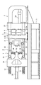
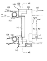
以下、本発明の実施形態について図面を参照しながら詳細に説明する。図1は本発明のダイカストマシンの概略平面図、図2はその概略正面図である。図において、土台であるフレーム21上の右端に固定ダイプレート23が固定され、該固定ダイプレート23から所定の距離を置いて左端にトグルサポート34がフレーム21に対してスライド自在に配設されている。そして、前記固定ダイプレート23とトグルサポート34との間に四本のタイバー12が架設されている。
Hereinafter, embodiments of the present invention will be described in detail with reference to the drawings. FIG. 1 is a schematic plan view of a die casting machine of the present invention, and FIG. 2 is a schematic front view thereof. In the figure, a
そして前記固定ダイプレート23に対向する移動ダイプレート1が、前記タイバー12にガイドされて固定ダイプレート23に近接離間可能に配設されている。該固定ダイプレート23と移動ダイプレート1との対向面がそれぞれ金型取付面23a、2aとなっており、移動金型K1、固定金型K2がそれぞれ装着できるようになっている。また、前記移動ダイプレート1の背面中央に突設された、後述するバックサポート部6内にエジェクタピンを移動させるためのエジェクタピン駆動装置Eが取り付けられるようになっている。
The
前記移動ダイプレート1とトグルサポート34との間には、型締装置としてのトグル機構Tが設けられ、前記トグルサポート34の背面には、型締用駆動手段としてのトグル駆動装置30(本実施例では油圧シリンダ)が取り付けられている。トグル駆動装置30は、油圧シリンダ等を駆動源とし、クロスヘッド35を進退させることによって、トグル機構Tを作動させる。
A toggle mechanism T as a mold clamping device is provided between the
トグル機構Tは前記クロスヘッド35に対して揺動自在に支持された連結レバー36、前記トグルサポート34に対して揺動自在に取り付けられたトグル作動レバー32、および、前記移動ダイプレート1に対して揺動自在に取り付けられたトグルアーム33から成り、前記トグル作動レバー32と連結レバー36との間、および、トグル作動レバー32とトグルアーム33との間がそれぞれリンク結合されている。これにより、前記移動ダイプレート1が固定ダイプレート23方向に前進して型閉した後、トグル機構Tにおいてトグル駆動装置30による推進力にトグル倍率を乗じた型締力を発生させ、該型締力による型締が行われる。勿論、トグル機構Tを使用することなく、トグル駆動装置30で直接型締することもできる。
The toggle mechanism T is connected to the connecting
移動ダイプレート1には、その四隅にそれぞれタイバー12が挿通されるタイバーガイド孔4が形成されており、それぞれのタイバーガイド孔4には、前方と後方にタイバーブッシュ12aがそれぞれ嵌め込まれ、潤滑剤を介して該タイバーブッシュ12aの内周面がタイバー12に沿って摺動して移動ダイプレート1が往復移動する。
The
移動ダイプレート1の本体部分で、略矩形の形状を持つ金型取付板2は、金型取付面2aを有しており、この金型取付面2aの中央部分には、例えば、移動金型K1内のキャビティに突出するエジェクタピン(図示せず)が収納されているエジェクタピン駆動装置Eのエジェクタロッドユニット(図示せず)を配設するための貫通孔51が穿設されている。
A
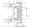
金型取付板2の厚さは、最低限、移動金型K1が装着するための取付溝2bが凹設され、且つ移動金型K1を保持して変形しない程度で足るが、安全をみてそれよりもやや厚くされている。金型取付板2の背面には、移動金型K1の外形をカバーするとともに、一定の幅Wを有し、その内側が凹設状に凹堀部5となっている略八角形凸畝状のバックサポート部6が設けられている。従って、バックサポート部6に囲まれている部分は略八角形凹設状の凹堀部5が形成されることになる。そしてこの部分にはエジェクタピン駆動装置Eが装着されるようになっている。
At least the thickness of the
バックサポート部6の上・下および両横の凸畝状辺6a〜6dは金型取付板2の上下両側辺に平行に設けられており、凸畝状辺6a〜6dの角部に設けられた傾斜凸畝状辺6e〜6hは本実施例ではやや立った状態(垂直の凸畝状辺6b、6dと成す角度が小さい状態)に形成されている。勿論、移動ダイプレート1の形状に合わせ、バックサポート部6の八角形凸畝状形状はそれに合わせて変形される。したがって、傾斜凸畝状辺6e〜6hは、もっと寝た状態(垂直の凸畝状辺6b、6dと成す角度が大きい状態)にすることもできる。角度としては、垂直の凸畝状辺6b、6dに対して60度〜30度の範囲に設けられる。
The upper, lower and both sides of the
そして、この傾斜凸畝状辺6e〜6hに対応する部分に移動金型K1の角部分が位置することになり、水平および垂直の凸畝状辺6a〜6dの部分に金型の上下および両側の辺が位置することになる。勿論、多少のはみ出しは金型取付板2に対して影響が生じない限り許容される。そしてタイバーガイド部3と傾斜凸畝状辺6e〜6hとの間には、両者を接続する補強リブ7がそれぞれ取り付けられている。
And the corner | angular part of the moving mold K1 will be located in the part corresponding to these inclined convex-shaped
前記金型取付板2の背面側上下辺にて上下の水平凸畝状辺6a、6cの外側に平行に辺部補強リブ6i、6jが設けられ、上下の水平凸畝状辺6a、6cを主にして該辺部補強リブ6i、6jにかけてトグルアーム33の軸支用としてのトグルアーム取付部8が後方に突出され、トグルアーム取付部8に掛かる型締力の大半をバックサポート部6が担持できるようになっている。また、本実施例では、トグルアーム取付部8はそれぞれ左右に分かれて形成されているが、単一のものであってもよいし、辺部補強リブ6i、6jを外して上下の水平凸畝状辺6a、6cだけに一体的に設けてもよい。
固定ダイプレート23には、射出スリーブ24を含む溶湯の射出装置Sが装備されている。
The fixed
次に、本発明装置の動作を説明する。図1に示されるトグル駆動装置30が作動してクロスヘッド35を前進させ、トグル機構Tを作動させる。これにより移動ダイプレート1が前進して移動金型K1が固定金型K2に接合して型閉が行われ、次いで、更なる型締力が作用して型締が行われる。続いて、射出装置Sから溶湯が高圧で射出されて前記金型Kのキャビティ空間に高圧充填され、背圧を掛けつつ溶湯を冷却凝固させ、ダイカスト成形品を成形する。続いてトグル駆動装置30が逆作動してクロスヘッド35を後退させ、移動ダイプレート1を後退させて移動金型K1を固定金型K2から離間させて型開を行い、図示されないエジェクタロッドを前進させてダイカスト成形品を取り出す。以上の動作を繰り返すことによってダイカスト成形品が成形される。
Next, the operation of the device of the present invention will be described. The
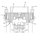
ここで、型締時には、トグル機構Tの上下のトグルアーム33からの推力F1、F2(型締力)が移動ダイプレート1のトグルアーム取付部8に作用するが、この推力(型締力)の大半は、トグルアーム取付部8に一体的に形成されているバックサポート部6の凸畝状辺6a、6cが担持することになり、これに続く他の凸畝状辺6b、6d、6e〜6hがその曲げモーメントを担持し、全体として前記推力F1、F2の大半を担持する。加えて矩形の斜線で示す大から小の移動金型K1の外周の範囲がバックサポート部6の幅Wの格子で示す範囲内に入っているために前記推力F1、F2によって金型取付板2の撓みや変形が回避される。このため、金型取付板2に作用する曲げモーメントが小さくなるので金型取付板2の板厚を厚くしなくても、金型取付板2が撓むことがない。
Here, at the time of mold clamping, thrusts F1 and F2 (mold clamping force) from the upper and
そしてバックサポート部6は円に近い略八角形状に形成されているため高圧型締力が加わっても捩れることが少なく、圧縮のみならず移動ダイプレート1の捩れなどにも大きな抵抗力を発揮する。
The
なお、本発明は前記実施の形態に限定されるものではなく、本発明の趣旨に基づいて種々変形させることが可能であり、それらを本発明の範囲から排除するものではない。 In addition, this invention is not limited to the said embodiment, It can change variously based on the meaning of this invention, and does not exclude them from the scope of the present invention.
M …ダイカストマシン
K1…金型
W …バックサポート部の幅
T …トグル機構
1 …移動ダイプレート
2 …金型取付板
2a…金型取付面
3 …タイバーガイド部
4 …タイバーガイド孔
5 …凹堀部
6 …バックサポート部
7 …補強リブ
8 …トグルアーム取付部
M ... Die casting machine K1 ... Mold W ... Back support part width T ...
Claims (2)
(b)前記金型取付板の背面にて、前記金型取付板に取り付けられた金型の外形をカバーするように設けられ、一定の幅を持ち、その内側が凹設状に凹堀部となっている略八角形凸畝状のバックサポート部と、
(c)前記バックサポート部に設けられた型締め用トグル機構用のトグルアーム取付部とで構成されたことを特徴とするダイカストマシンの移動ダイプレート。 (A) a mold mounting plate provided at the four corners with a mold mounting surface, and tie bar guide portions in which tie bar guide holes through which the tie bars are inserted;
(B) The back surface of the mold mounting plate is provided so as to cover the outer shape of the mold mounted on the mold mounting plate, has a certain width, and has a concave moat portion on the inner side thereof. A substantially octagonal ridge-shaped back support portion,
(C) A moving die plate for a die casting machine, comprising a toggle arm mounting portion for a clamping mechanism for a clamping mechanism provided in the back support portion.
Priority Applications (1)
| Application Number | Priority Date | Filing Date | Title |
|---|---|---|---|
| JP2008251299A JP5555414B2 (en) | 2008-09-29 | 2008-09-29 | Die casting machine moving die plate |
Applications Claiming Priority (1)
| Application Number | Priority Date | Filing Date | Title |
|---|---|---|---|
| JP2008251299A JP5555414B2 (en) | 2008-09-29 | 2008-09-29 | Die casting machine moving die plate |
Publications (2)
| Publication Number | Publication Date |
|---|---|
| JP2010082630A true JP2010082630A (en) | 2010-04-15 |
| JP5555414B2 JP5555414B2 (en) | 2014-07-23 |
Family
ID=42247110
Family Applications (1)
| Application Number | Title | Priority Date | Filing Date |
|---|---|---|---|
| JP2008251299A Expired - Fee Related JP5555414B2 (en) | 2008-09-29 | 2008-09-29 | Die casting machine moving die plate |
Country Status (1)
| Country | Link |
|---|---|
| JP (1) | JP5555414B2 (en) |
Cited By (3)
| Publication number | Priority date | Publication date | Assignee | Title |
|---|---|---|---|---|
| CN101983802A (en) * | 2010-11-23 | 2011-03-09 | 苏州三基铸造装备股份有限公司 | Novel moving die seat plate for die casting machine |
| EP3147097A1 (en) * | 2015-09-24 | 2017-03-29 | Sumitomo Heavy Industries, Ltd. | Injection molding machine |
| CN106623849A (en) * | 2016-11-25 | 2017-05-10 | 芜湖市容川机电科技股份有限公司 | Thick nodular cast iron workpiece die-casting machine template |
Citations (2)
| Publication number | Priority date | Publication date | Assignee | Title |
|---|---|---|---|---|
| JPH0420422U (en) * | 1990-06-08 | 1992-02-20 | ||
| JP2003089133A (en) * | 2001-07-13 | 2003-03-25 | Sumitomo Heavy Ind Ltd | Movable mold support device for injection molding machine |
-
2008
- 2008-09-29 JP JP2008251299A patent/JP5555414B2/en not_active Expired - Fee Related
Patent Citations (2)
| Publication number | Priority date | Publication date | Assignee | Title |
|---|---|---|---|---|
| JPH0420422U (en) * | 1990-06-08 | 1992-02-20 | ||
| JP2003089133A (en) * | 2001-07-13 | 2003-03-25 | Sumitomo Heavy Ind Ltd | Movable mold support device for injection molding machine |
Cited By (3)
| Publication number | Priority date | Publication date | Assignee | Title |
|---|---|---|---|---|
| CN101983802A (en) * | 2010-11-23 | 2011-03-09 | 苏州三基铸造装备股份有限公司 | Novel moving die seat plate for die casting machine |
| EP3147097A1 (en) * | 2015-09-24 | 2017-03-29 | Sumitomo Heavy Industries, Ltd. | Injection molding machine |
| CN106623849A (en) * | 2016-11-25 | 2017-05-10 | 芜湖市容川机电科技股份有限公司 | Thick nodular cast iron workpiece die-casting machine template |
Also Published As
| Publication number | Publication date |
|---|---|
| JP5555414B2 (en) | 2014-07-23 |
Similar Documents
| Publication | Publication Date | Title |
|---|---|---|
| JP4364902B2 (en) | Mold support apparatus, molding machine and molding method | |
| JP4550649B2 (en) | Moving die support device and mold clamping device | |
| JP4625488B2 (en) | Mold platen, mold clamping device, injection molding machine | |
| US10710290B2 (en) | Mold platen, mold clamping device, injection molding device | |
| JP2006326962A (en) | Injection molding machine | |
| JP5555414B2 (en) | Die casting machine moving die plate | |
| JP2008162103A (en) | Mold clamping device and injection molding machine equipped therewith | |
| JP6820178B2 (en) | Molding machine | |
| JP4335574B2 (en) | Moving die support device and mold clamping device | |
| JP5394802B2 (en) | Injection molding method and injection molding apparatus | |
| JP2003025400A (en) | Mold clamping unit for molding machine | |
| KR20090007984A (en) | Diecasting apparatus | |
| JP5976567B2 (en) | Injection molding machine | |
| JP5976568B2 (en) | Injection molding machine | |
| JPH08267463A (en) | Movable plate of mold clamping device | |
| JP3889295B2 (en) | Molding device clamping machine | |
| JP5695291B2 (en) | Die casting machine | |
| JP6587879B2 (en) | Injection molding machine | |
| JP6678017B2 (en) | Injection molding machine with clamp unit | |
| JP4172775B2 (en) | Mold | |
| CN216325006U (en) | Local extrusion device of horizontal die casting machine | |
| JP2005212370A (en) | Manufacturing equipment for resin molded article | |
| KR100763537B1 (en) | Mold support device, molding machine, and molding method | |
| JP4513594B2 (en) | Injection molding machine | |
| JP2009067027A (en) | Mold platen, mold clamping device, injection molding machine |
Legal Events
| Date | Code | Title | Description |
|---|---|---|---|
| A621 | Written request for application examination |
Free format text: JAPANESE INTERMEDIATE CODE: A621 Effective date: 20110912 |
|
| A521 | Request for written amendment filed |
Free format text: JAPANESE INTERMEDIATE CODE: A523 Effective date: 20120829 |
|
| A977 | Report on retrieval |
Free format text: JAPANESE INTERMEDIATE CODE: A971007 Effective date: 20130612 |
|
| A131 | Notification of reasons for refusal |
Free format text: JAPANESE INTERMEDIATE CODE: A131 Effective date: 20130618 |
|
| A521 | Request for written amendment filed |
Free format text: JAPANESE INTERMEDIATE CODE: A523 Effective date: 20130819 |
|
| A02 | Decision of refusal |
Free format text: JAPANESE INTERMEDIATE CODE: A02 Effective date: 20131203 |
|
| A521 | Request for written amendment filed |
Free format text: JAPANESE INTERMEDIATE CODE: A523 Effective date: 20140226 |
|
| A521 | Request for written amendment filed |
Free format text: JAPANESE INTERMEDIATE CODE: A821 Effective date: 20140228 |
|
| A911 | Transfer to examiner for re-examination before appeal (zenchi) |
Free format text: JAPANESE INTERMEDIATE CODE: A911 Effective date: 20140324 |
|
| TRDD | Decision of grant or rejection written | ||
| A01 | Written decision to grant a patent or to grant a registration (utility model) |
Free format text: JAPANESE INTERMEDIATE CODE: A01 Effective date: 20140507 |
|
| A61 | First payment of annual fees (during grant procedure) |
Free format text: JAPANESE INTERMEDIATE CODE: A61 Effective date: 20140602 |
|
| R150 | Certificate of patent or registration of utility model |
Ref document number: 5555414 Country of ref document: JP Free format text: JAPANESE INTERMEDIATE CODE: R150 |
|
| LAPS | Cancellation because of no payment of annual fees |