JP2010081534A - Packet analyzing apparatus, program and method - Google Patents
Packet analyzing apparatus, program and method Download PDFInfo
- Publication number
- JP2010081534A JP2010081534A JP2008250478A JP2008250478A JP2010081534A JP 2010081534 A JP2010081534 A JP 2010081534A JP 2008250478 A JP2008250478 A JP 2008250478A JP 2008250478 A JP2008250478 A JP 2008250478A JP 2010081534 A JP2010081534 A JP 2010081534A
- Authority
- JP
- Japan
- Prior art keywords
- packet
- input
- output
- data
- communication device
- Prior art date
- Legal status (The legal status is an assumption and is not a legal conclusion. Google has not performed a legal analysis and makes no representation as to the accuracy of the status listed.)
- Granted
Links
Images


Landscapes
- Data Exchanges In Wide-Area Networks (AREA)
Abstract
Description
この発明は、パケット解析装置、プログラム及び方法に関し、例えば、メディア変換装置の装置内遅延時間の算出に適用することができる。 The present invention relates to a packet analysis device, a program, and a method, and can be applied to, for example, calculation of an in-device delay time of a media conversion device.
従来、メディア変換装置に入力されたReal−time Transport protocol(RTP)パケット(非特許文献1、2参照)が、メディア変換されたRTPパケットとして出力されるまでの装置内遅延時間を、外部のパケット解析装置を用いて解析する方法としては、図8に示すように、メディア変換装置が接続されたスイッチ(以下、「SW」という)のミラーリング機能(パケットをコピーし、パケット解析装置に取得させる)により、送信側通信装置からメディア変換装置に入力されるRTPパケットと、メディア変換装置から受信側通信装置に向けて送出されるRTPパケットとを、パケット解析装置に一定時間取得(パケットキャプチャ)させ、その後パケット解析装置に保持されているRTPパケットについて、RTPシーケンス番号などを用いて、メディア変換装置における入力側と出力側のRTPパケットの対応付け(以下、「紐付け」ともいう)を行い、紐付けされたRTPパケットを取得したタイミング、すなわちメディア変換装置において入力又は出力されたタイミングに基づいて、メディア変換装置における装置内処理時間を算出する。なお、RTPシーケンス番号は、RTPパケットごとに付与されるユニークな値である。
Conventionally, a real-time transport protocol (RTP) packet (refer to
通常メディア変換装置では、入力されたRTPパケットを処理して出力する際には、RTPシーケンス番号は、別の体系の番号に再付与されるために、入力側と出力側で、RTPシーケンス番号が一致することをもって紐付けすることはできない。よって、従来通常のパケット解析の方式では、送信側通信装置からRTPパケットが最初にメディア変換装置に入力される前から、パケット解析装置が、メディア変換装置に入出力されるRTPパケットのキャプチャを開始し、入出力されるRTPパケットの一つ目から順番に紐付けをする必要がある。
しかしながら、従来のパケット解析の方法では、送信側通信装置からRTPパケットが最初にメディア変換装置に入力される前から、パケット解析装置が、メディア変換装置に入出力されるRTPパケットのキャプチャを開始する必要があるので、通信途中からキャプチャを開始した場合には、メディア変換装置における入力側と出力側のRTPパケットの紐付けはできないという問題がある。 However, in the conventional packet analysis method, the packet analysis device starts capturing RTP packets input / output to / from the media conversion device before the RTP packet is first input from the transmission side communication device to the media conversion device. Therefore, there is a problem that when the capture is started in the middle of communication, the RTP packet on the input side and the output side in the media conversion device cannot be linked.
そのため、入力側通信装置から出力側通信装置へ送出されたパケットを処理するパケット処理装置に入出力されるパケット解析において、入力側通信装置から出力側通信装置への通信開始後に、パケット処理装置に入出力されるパケットを紐付けすることができるパケット解析装置、プログラム及び方法が望まれている。 Therefore, in the packet analysis input / output to / from the packet processing device that processes the packet sent from the input side communication device to the output side communication device, after the start of communication from the input side communication device to the output side communication device, A packet analysis apparatus, program, and method that can link input and output packets are desired.
第1の本発明のパケット解析装置は、(1)第1の通信装置から第2の通信装置に向けて送出されたパケットを処理して、上記第2の通信装置に向けて送出するパケット処理装置に入出力されるパケットに係る解析を行うパケット解析装置において、(2)上記第1の通信装置から上記パケット処理装置に入力された、データが挿入された入力データパケットと、上記パケット処理装置から上記第2の通信装置に向けて送出された、データが挿入された出力データパケットとを保持するデータパケット保持手段と、(3)上記第1の通信装置から上記パケット処理装置に入力された、所定の種類のパケットである入力基準パケットと、上記パケット処理装置から上記第2の通信装置に向けて送出された、所定の種類のパケットである出力基準パケットについて、上記パケット処理装置による処理前と処理後で対応する組を特定する基準パケット対応特定手段と、(4)少なくとも、上記基準パケット対応特定手段により対応付けを特定された、入力基準パケットが上記パケット処理装置に入力されたタイミングと、出力基準パケットが上記パケット処理装置から出力されたタイミングとに基づいて、上記データパケット保持手段に保持されている、入力データパケット及び出力データパケットについて上記パケット処理装置による処理前と処理後で対応する組を特定するデータパケット対応特定手段とを有することを特徴とする。 The packet analysis device according to the first aspect of the present invention provides (1) packet processing for processing a packet sent from the first communication device to the second communication device and sending the packet to the second communication device. In the packet analysis device for performing analysis relating to a packet input / output to / from the device, (2) an input data packet into which data is inserted, which is input from the first communication device to the packet processing device, and the packet processing device A data packet holding means for holding an output data packet into which data is inserted, sent from the first communication device to the second communication device; and (3) input from the first communication device to the packet processing device. An input reference packet that is a predetermined type of packet, and an output reference that is a predetermined type of packet sent from the packet processing device to the second communication device Reference packet correspondence specifying means for specifying a pair corresponding to a packet before and after processing by the packet processing device; and (4) at least an input reference packet whose correspondence is specified by the reference packet correspondence specifying means. Based on the timing input to the packet processing device and the timing at which the output reference packet is output from the packet processing device, the input data packet and the output data packet held in the data packet holding means Data packet correspondence specifying means for specifying a pair corresponding to before and after processing by the processing device is provided.
第2の本発明のパケット解析プログラムは、(1)第1の通信装置から第2の通信装置に向けて送出されたパケットを処理して、上記第2の通信装置に向けて送出するパケット処理装置に入出力されるパケットに係る解析を行うパケット解析装置に搭載されたコンピュータを、(2)上記第1の通信装置から上記パケット処理装置に入力された、データが挿入された入力データパケットと、上記パケット処理装置から上記第2の通信装置に向けて送出された、データが挿入された出力データパケットとを保持するデータパケット保持手段と、(3)上記第1の通信装置から上記パケット処理装置に入力された、所定の種類のパケットである入力基準パケットと、上記パケット処理装置から上記第2の通信装置に向けて送出された、所定の種類のパケットである出力基準パケットについて、上記パケット処理装置による処理前と処理後で対応する組を特定する基準パケット対応特定手段と、(4)少なくとも、上記基準パケット対応特定手段により対応付けを特定された、入力基準パケットが上記パケット処理装置に入力されたタイミングと、出力基準パケットが上記パケット処理装置から出力されたタイミングとに基づいて、上記データパケット保持手段に保持されている、入力データパケット及び出力データパケットについて上記パケット処理装置による処理前と処理後で対応する組を特定するデータパケット対応特定手段として機能させることを特徴とする。 The packet analysis program according to the second aspect of the present invention provides (1) packet processing for processing a packet sent from the first communication device to the second communication device and sending the packet to the second communication device. (2) an input data packet into which data has been inserted, which is input from the first communication device to the packet processing device; A data packet holding means for holding an output data packet into which data is inserted, sent from the packet processing device to the second communication device; and (3) the packet processing from the first communication device. An input reference packet that is a predetermined type of packet input to the device, and a predetermined type that is transmitted from the packet processing device to the second communication device A reference packet correspondence specifying means for specifying a pair corresponding to an output reference packet that is a packet before and after processing by the packet processing device; and (4) at least correspondence is specified by the reference packet correspondence specifying means The input data packet and the output are held in the data packet holding unit based on the timing when the input reference packet is input to the packet processing device and the timing when the output reference packet is output from the packet processing device. The data packet is made to function as a data packet correspondence specifying means for specifying a pair corresponding to the data packet before and after processing by the packet processing device.
第3の本発明のパケット解析方法は、(1)第1の通信装置から第2の通信装置に向けて送出されたパケットを処理して、上記第2の通信装置に向けて送出するパケット処理装置に入出力されるパケットに係る解析を行うパケット解析方法において、(2)データパケット保持手段、基準パケット対応特定手段、データパケット対応特定手段を有し、(3)上記データパケット保持手段は、上記第1の通信装置から上記パケット処理装置に入力された、データが挿入された入力データパケットと、上記パケット処理装置から上記第2の通信装置に向けて送出された、データが挿入された出力データパケットとを保持し、(4)上記基準パケット対応特定手段は、上記第1の通信装置から上記パケット処理装置に入力された、所定の種類のパケットである入力基準パケットと、上記パケット処理装置から上記第2の通信装置に向けて送出された、所定の種類のパケットである出力基準パケットについて、上記パケット処理装置による処理前と処理後で対応する組を特定し、(5)上記データパケット対応特定手段は、少なくとも、上記基準パケット対応特定手段により対応付けを特定された、入力基準パケットが上記パケット処理装置に入力されたタイミングと、出力基準パケットが上記パケット処理装置から出力されたタイミングとに基づいて、上記データパケット保持手段に保持されている、入力データパケット及び出力データパケットについて上記パケット処理装置による処理前と処理後で対応する組を特定することを特徴とする。 The packet analysis method according to the third aspect of the present invention includes (1) packet processing for processing a packet sent from the first communication device to the second communication device and sending the packet to the second communication device. In a packet analysis method for analyzing a packet input to and output from an apparatus, (2) a data packet holding unit, a reference packet correspondence specifying unit, and a data packet correspondence specifying unit are provided. (3) The data packet holding unit includes: An input data packet into which data is inserted, which is input from the first communication device to the packet processing device, and an output into which data is inserted, which is sent from the packet processing device to the second communication device. (4) the reference packet correspondence specifying means is a packet of a predetermined type inputted from the first communication device to the packet processing device. The input reference packet that is a packet and the output reference packet that is a predetermined type of packet that is sent from the packet processing device to the second communication device before and after the processing by the packet processing device (5) the data packet correspondence specifying means includes at least a timing at which an input reference packet is input to the packet processing apparatus, whose correspondence is specified by the reference packet correspondence specifying means, and an output reference; Based on the timing when the packet is output from the packet processing device, the input data packet and the output data packet held in the data packet holding unit are set corresponding to before and after processing by the packet processing device. It is characterized by specifying.
本発明によれば、入力側通信装置から出力側通信装置へ送出されたパケットを処理するパケット処理装置に入出力されるパケット解析において、入力側通信装置から出力側通信装置への通信開始後に、パケット処理装置に入出力されるパケットを紐付けすることができる。 According to the present invention, in packet analysis input / output to / from a packet processing device that processes a packet sent from an input-side communication device to an output-side communication device, after starting communication from the input-side communication device to the output-side communication device, Packets input / output to / from the packet processing device can be linked.
(A)主たる実施形態
以下、本発明によるパケット解析装置、プログラム及び方法の一実施形態を、図面を参照しながら詳述する。
(A) Main Embodiment Hereinafter, an embodiment of a packet analysis device, a program, and a method according to the present invention will be described in detail with reference to the drawings.
(A−1)実施形態の構成
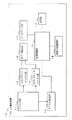
図2は、この実施形態に係る通信システム1全体の機能的構成を示すブロック図である。
(A-1) Configuration of Embodiment FIG. 2 is a block diagram showing a functional configuration of the
図2において、通信システム1には、パケット解析装置10、メディア変換装置20、SW31、32、2台の通信装置41、42、ネットワークN1、N2が配置されている。
In FIG. 2, the
通信装置41、42は、図2に示す通りそれぞれネットワークN1、ネットワークN2に接続している通信端末であり、メディア変換装置20を介して、RTP、RTP Control Protocol(RTCP;IETF RFC3605参照)を用いて通信を行うものである。
The communication devices 41 and 42 are communication terminals connected to the network N1 and the network N2, respectively, as shown in FIG. 2, and use RTP, RTP Control Protocol (RTCP; see IETF RFC3605) via the
SW31は、メディア変換装置20を、ネットワークN1に接続させるスイッチングハブである。また、SW32は、メディア変換装置20を、ネットワークN2に接続させるためのスイッチである。図2において、SW31、32は、メディア変換装置20において入出力されるパケットを、例えば、ポートミラーリングの機能などによりパケット解析装置10が接続しているポートに転送するように設定されているものとする。図2においては、メディア変換装置20において入出力されるパケットを、SW31、32のポートミラーリングの機能により、パケット解析装置10が接続しているポートに転送しているが、直接メディア変換装置20に接続しても良く、メディア変換装置20において入出力されるパケットを、パケット解析装置10が取得するための構成は限定されないものである。
The
メディア変換装置20は、通信装置41、42の間のRTP、RTCPを相互接続させるための、音声パケットや映像パケットなどのメディア変換を行うものである。
The
パケット解析装置10は、上述の通り、SW31、32を介してメディア変換装置20において入出力されるパケットを取得(キャプチャリング)し、メディア変換装置20における装置内遅延時間に係る時間を算出するものである。ディア変換装置20における装置内遅延時間とは、例えば、メディア変換装置20が送信側の通信装置からパケットを取得してから、変換し、パケットを受信側の通信装置に送信開始するまでの時間をいう。また、例えば、RTPパケットにおいて送信するデータが、映像コーデックなど複数のRTPパケットで一枚の画像を構成される場合には、一枚の画像についてメディア変換装置20が、最後のRTPパケットを受信してから、変化後最初のRTPパケットを送信し始めるまでの時間を装置内遅延時間としても良い。でぃあ
図1は、パケット解析装置10内部の機能的構成について示したブロック図である。
As described above, the packet analysis device 10 acquires (captures) packets input / output in the
パケット解析装置10は、フィルタ部11、入力パケットバッファ部12、出力パケットバッファ部13、RTP検出部14、制御処理部15、RTCP検出部16、データベース部17、解析対象登録部18、出力部19を有している。
The packet analysis device 10 includes a filter unit 11, an input
パケット解析装置10は、CPU、ROM、RAM、EEPROM、ハードディスクなどのプログラムの実行構成、及び、他の通信装置と通信をするためのインターフェースを有する装置(1台に限定されず、複数台を分散処理し得るようにしたものであっても良い。)に、実施形態のパケット解析プログラム等をインストールすることにより構築されるものであり、機能的には上述の図1のように示すことができる。 The packet analysis device 10 includes a program execution configuration such as a CPU, ROM, RAM, EEPROM, and hard disk, and a device having an interface for communicating with other communication devices (not limited to one, but a plurality of devices are distributed) It is constructed by installing the packet analysis program of the embodiment, etc., and can be functionally shown as in FIG. 1 described above. .
解析対象登録部18には、解析対象登録部18において、装置内遅延時間を算出する対象の通信に係る端末の識別情報の組が登録されているものとする。この実施形態においては、例として、解析対象登録部18には、送信側の通信装置として通信装置41のIPアドレス(192.168.0.1)が登録されており、受信側の通信装置として通信装置42のIPアドレス(192.168.0.2)の組が、登録されているものとする。すなわち、パケット解析装置10においては、解析対象登録部18の登録内容により、通信装置41から通信装置42に向けて送出されたパケットが解析の対象となる。説明を簡易とするため、この実施形態においては、解析対象登録部18には一組のIPアドレスのみが登録されているものとして説明するが、複数の組を登録するようにしても良い。また、解析対象登録部18に登録する端末の識別情報としては、IPアドレスに限定されず、マックアドレスやドメイン名等、端末を識別することができる情報であれば良い。
In the analysis
フィルタ部11は、取得した全パケットから、装置内遅延時間を算出する対象となるパケット(以下、「対象パケット」という)を抽出する。この実施形態においては、フィルタ部11は、対象パケットとして、解析対象登録部18に登録されているIPアドレスを送信元及び送信先アドレスとするRTPパケット、又は、RTCPパケットのうちSender reportに係るパケット(以下、「送信者レポートパケット」という)であるものとする。すなわち、図1においては、フィルタ部11は、通信装置41から通信装置42に向けて送出されたRTPパケット及び送信者レポートパケットを、対象パケットとして抽出する。フィルタ部11において、RTP又は送信者レポートパケットは、取得したパケットのヘッダ情報などを参照することにより識別されるものとする。
The filter unit 11 extracts a packet (hereinafter referred to as “target packet”) from which the in-device delay time is calculated from all the acquired packets. In this embodiment, the filter unit 11 uses the IP address registered in the analysis
また、フィルタ部11は、対象パケットのうち、RTPパケットのデータを、入力パケットバッファ部12、又は、出力パケットバッファ部13に与え、RTCPパケットのデータをRTCP検出部16に与える。
Also, the filter unit 11 provides the RTP packet data of the target packet to the input
フィルタ部11は、対象パケットのうち、メディア変換装置20に入力されたパケットに係るデータを、入力パケットバッファ部12に与え、メディア変換装置20から出力されたパケットに係るデータを、出力パケットバッファ部13に与える。フィルタ部11において、対象パケットが、メディア変換装置20において入力されたパケットか、出力されたパケットかを識別する方法としては、例えば、パケット解析装置10がパケットを取得する際に経由したSWに応じて判定しても良いし、パケットの送信先のレイヤ2(MAC)アドレスがメディア変換装置20のアドレスになっている場合にはメディア変換装置20に入力されたパケットと判定し、逆に送信元が該当する場合にはメディア変換装置20から出力されたパケットと判定するなど、メディア変換装置20において入力されたパケットか、出力されたパケットかを識別する方法は限定されないものである。
The filter unit 11 gives the data related to the packet input to the
フィルタ部11は、入力パケットバッファ部12、出力パケットバッファ部13にRTPパケットを与える際に、アプリケーション(レイヤ5:RTP)層以上のデータを与え、レイヤ4以下のデータは廃棄するようにしても良い。また、フィルタ部11は、RTCP検出部16に送信者レポートパケットを与える際に、アプリケーション(レイヤ5:RTCP)層以上のデータを与え、レイヤ4以下のデータは廃棄するようにしても良い。
When the RTP packet is given to the input
入力パケットバッファ部12、出力パケットバッファ部13は、それぞれフィルタ部11から与えられたRTPパケットを保持するバッファの機能を担っている。また、入力パケットバッファ部12、出力パケットバッファ部13は、フィルタ部11からRTPパケットが与えられると、RTPパケットのデータと、そのRTPパケットを与えられた時間(以下、「取得時間」という)の情報を組みとして記憶する。取得時刻は、例えば、パケット解析装置10が起動してから現在までの時間としても良い。なお、取得時間は、それぞれのRTPパケットを、フィルタ部11が取得した時間としても良いが、フィルタ部11における処理時間が、パケット解析装置10における解析において無視し得るような誤差の範囲である場合には、この実施形態のように、入力パケットバッファ部12、出力パケットバッファ部13にRTPパケットが与えられた時点を取得時間とするようにしても良い。また、パケット解析装置10においては、上述の取得時間を、メディア変換装置20において、パケットが入力又は出力された時間とみなして、パケット解析を行うようにしても良い。
The input
また、入力パケットバッファ部12、出力パケットバッファ部13は、制御処理部15からの制御に応じて、保持しているRTPパケットのデータを廃棄する。
Further, the input
RTP検出部14は、入力パケットバッファ部12、出力パケットバッファ部13に保持されているRTPパケットから、パケット解析に必要な情報を抽出して、制御処理部15に与える。RTP検出部14がRTPパケットから抽出する情報としては、取得時間、各RTPパケットのRTPペイロード量の検出、RTPシーケンス番号の検出、RTPへッダ内のPayload Type(以下、「PT」という)値情報が挙げられる。
The
RTCP検出部16は、フィルタ部11からRTCPパケットが与えられると、そのRTCPパケットから、パケット解析に必要な情報を抽出して、制御処理部15に与える。RTCP検出部16が、RTCPパケットから抽出する情報としては、Sender‘s packet count値(以下、「送信者パケットカウント値」という)、RTPタイムスタンプ値が挙げられる。
When the RTCP packet is given from the filter unit 11, the
データベース部17は、メディア変換装置20が対応するコーデック(メディア)に係る情報を格納している。
The
図3は、データベース部17に登録する情報の例について示した説明図である。
FIG. 3 is an explanatory diagram showing an example of information registered in the
データベース部17が格納する情報の一つとしては、例えば、図4に示すように、メディア変換装置20が対応するコーデックごとの、分割周期とペイロード長の情報と、PT値を登録するようにしても良い。
As information stored in the
出力部19は、制御処理部15における処理結果等を出力する手段である。出力部19による出力は、例えば、ディスプレイ等の表示装置に表示出力させたり、ディスク装置等の記憶装置に記憶させたり、プリンタ等の印刷装置に印刷出力させたりする構成としてもよく、その出力方法は問われないものである。
The
制御処理部15は、パケット解析装置10全体を制御する機能を担っており、例えば、制御処理部15は、フィルタ部11の設定や、入力パケットバッファ部12、出力パケットバッファ部13のデータ廃棄などの制御を行う。
The
また、制御処理部15は、RTP検出部14、RTCP検出部16から与えられた情報と、データベース部17に登録されている情報に基づいて、出力パケットバッファ部13に保持されているパケットが、入力パケットバッファ部12に保持されているパケットのうちいずれのパケットと紐付けできるかを検出する。紐付けできるパケットとは、メディア変換装置20により変換前と変換後で対応するパケットのことである。そして、制御処理部15は、紐付けされたRTPパケットの取得時間に基づいて装置内遅延時間が算出される。例えば、紐付けされたRTPパケットについて、出力側のRTPパケットの取得時間から、入力側のRTPパケットの取得時間を減算した時間が、装置内遅延時間となる。
Further, the
また、制御処理部15は、入力パケットバッファ部12と、出力パケットバッファ部13が保持しているRTPパケットについて、音声コーデックに係るパケットであるのか、映像コーデックに係るパケットであるのかを判定する。音声コーデックに係るパケットであるのか、映像コーデックに係るパケットであるのかによって、RTPパケットを紐付けするための処理手順が異なるためである。制御処理部15が、音声コーデックに係るパケットであるのか、映像コーデックに係るパケットであるのかを判定する手段としては、例えば、PT値を、RTP検出部14を介して取得して判定してもよい。
Further, the
また、制御処理部15は、対象パケットが音声コーデックに係るパケットである場合には、送信者レポートパケット及びRTPパケットの紐付けを行うために必要な処理として、RTP検出部14を制御して、入力パケットバッファ部12と、出力パケットバッファ部13が保持している任意のRTPパケットについて、それぞれのRTPパケットの形式に係る情報を取得し、メディア変換装置20における入力側のパケット分割周期と、出力側のパケット分割周期の対応関係を解析する。
In addition, when the target packet is a packet related to the voice codec, the
制御処理部15が、パケット分割周期を解析する方法としては、例えば、RTP検出部14を制御して、入力パケットバッファ部12と、出力パケットバッファ部13が保持している任意のRTPパケットについて、それぞれのヘッダ内のPT値及びペイロード長が一致する場合には、パケット分割周期は同一、すなわち、入力側のRTPパケット1つに対して、出力側のRTPパケットの1つのパケットが対応すると判定してもよい。
As a method for the
また、制御処理部15が、パケット分割周期を解析する方法としては、例えば、RTPパケットのペイロード量とPT値の情報を、RTP検出部14を介して取得し、取得した情報に該当するコーデックのパケット分割周期を、データベース部17に保持されている情報から検索し、入力側のパケット分割周期と、出力側のパケット分割周期の最小公倍数を求めることにより、メディア変換装置20における入力側のパケット分割周期と、出力側のパケット分割周期の対応関係を解析しても良い。例えば、出力パケットバッファ部13が保持しているRTPパケットのPT値が18で、ペイロード長が160バイトの場合、パケット分割周期は20msecと判定できる。また、例えば、入力パケットバッファ部12が保持しているRTPパケットのPT値が8で、ペイロード長が40バイトの場合、パケット分割周期は40msecと判定できる。この例の場合、メディア変換装置20における入力側のパケット分割周期は20msecで、出力側のパケット分割周期が40msecであるので、最小公倍数としては、入力側のパケット分割周期1に対して出力側のパケット分割周期は2であるので、入力側のRTPパケット1つに対して、出力側のRTPパケットの2つのパケットが対応すると判定することができる
制御処理部15は、入力パケットバッファ部12と、出力パケットバッファ部13が保持しているRTPパケットについて、音声コーデックに係るパケットであると判定した場合には、さらに、入力側と出力側で、送信者レポートパケットについて紐付けされるものを特定し、この紐付けされる送信者レポートパケットを基準のパケット(以下、「基準パケット」という)として、それ以降または以前に、入力側及び出力側において取得されるRTPパケットが紐付けされる(詳細については、後述する動作説明において説明する)。
In addition, as a method for the
メディア変換装置20に入出力されるRTPパケットが、映像コーデックの場合は、メディア変換装置20内で、デコード・エンコードを実施するので、入出力するRTPパケットの数は、コーデックなどが同一であっても一致するとは限らない。また、映像コーデックである場合には、複数のRTPパケットにより1つのフレームが形成される。よって、1つのフレームを形成する1番目のパケットと、最後のパケットを特定することが必要になる。1つのフレームにおいて、1番目のRTPパケットは、ペイロード部のメディアヘッダ部にスタートビットフラグが所定のビット表示(この実施形態においては、「0001」であるものとする)となり、最後のRTPパケットにはRTPヘッダ部のマーカビットフラグが「1」になっているというプロトコルであるものとする。そこで、この実施形態において、制御処理部15は、入力パケットバッファ部12と、出力パケットバッファ部13が保持しているRTPパケットについて、映像コーデックに係るパケットであると判定した場合には、RTP検出部14を制御して、対象パケットについてさらにスタートビット・マークビット検出に係る情報を取得し、それらの情報も利用して、RTPパケットの紐付けを行う(詳細については、後述する動作説明において説明する)。
If the RTP packet input / output to / from the
また、対象パケットが、映像コーデックに係るパケットである場合は、基準パケットとしては、上述の音声コーデックの場合のように、送信者レポートパケットではなく、他の基準となるパケットを用いるようにしても良い。 When the target packet is a packet related to a video codec, a reference packet other than the sender report packet may be used as the reference packet, as in the case of the audio codec described above. good.
例えば、映像コーデックとしてMPEGを用いている場合、映像フレームは、1つの映像フレーム内で符号化が完結しているIフレーム(Intra−coded Frame)、時間的に前のフレームから動き予測するPフレーム(Predicted Frame)、時間的に前および後ろのフレームを使って動き予測するBフレーム(Bi−directional Predicted Frame)の3つである。Iフレームから次のIフレームの間のフレーム集合を1組と捉え、これをGOP(Group Of Pictures)と呼ばれる。利用用途や製品によって異なるが、Iフレームは通常15〜30フレーム間隔で入れられている。この実施形態においては、送信者レポートパケットではなく、このIフレームを構成するRTPパケットを基準パケットとして、入力側と出力側とで、そのIフレーム以前又は以降のRTPパケットについて紐付けを行うものとして説明する。 For example, when MPEG is used as a video codec, a video frame is an I-frame (Intra-coded Frame) that has been encoded within one video frame, or a P-frame that predicts motion from a temporally previous frame. (Predicted Frame) is a B-frame (Bi-directional Predicted Frame) for predicting motion using temporally forward and backward frames. A set of frames between an I frame and the next I frame is regarded as one set, and this is called GOP (Group Of Pictures). I frames are usually inserted at intervals of 15 to 30 frames, depending on the application and product. In this embodiment, it is assumed that RTP packets constituting this I frame, not the sender report packet, are used as reference packets, and RTP packets before or after the I frame are linked on the input side and output side. explain.
なお、メディア変換装置20において、映像コーデックとしてMPEG以外の方式が用いられていた場合でも、Iフレームに相当する1つの映像フレーム内で符号化が完結している基準となるフレームと、そのフレームを基準とした差分のデータを有する複数のフレームでGOPと同様のグループが形成される方式である場合には、基準となるフレームに係るパケットを基準パケットとして適用するようにしても良い。
In the
それぞれのフレームの種類を識別する方法としては、各RTPパケットに挿入されているデータにおいて、フレームの種類を識別する情報を参照することにより行っても良いし、各フレームのデータ量に応じて判定しても良い。PフレームやBフレームのデータ量はIフレームに比べて小さいので、RTPパケットごとのデータ量からIフレームを検出できる。なお、各フレームのデータ量は、例えば、各フレームを構成するRTPパケットのペイロード長を合計することにより求めても良い。 As a method for identifying the type of each frame, the data inserted in each RTP packet may be referred to by referring to information for identifying the type of frame, or determined according to the data amount of each frame. You may do it. Since the data amount of the P frame and the B frame is smaller than that of the I frame, the I frame can be detected from the data amount of each RTP packet. Note that the data amount of each frame may be obtained, for example, by summing up the payload lengths of the RTP packets constituting each frame.
各フレームについて、データ量に応じてIフレームを検出する手段としては、例えば、閾値を設けて、閾値よりもデータ量の多いフレームをIフレームと特定するようにしても良い。例えば、B又はPフレームのデータ量が1000〜2000バイト、Iフレームが6000〜7000バイトであった場合には、5000バイト以上のフレームをIフレームと特定するようにしても良い。 For each frame, as means for detecting an I frame according to the data amount, for example, a threshold value may be provided, and a frame having a data amount larger than the threshold value may be specified as an I frame. For example, when the data amount of the B or P frame is 1000 to 2000 bytes and the I frame is 6000 to 7000 bytes, a frame of 5000 bytes or more may be specified as the I frame.
また、例えば、第1のフレームのデータ量と、第1のフレームの直前又は直後に発生した第2のフレームのデータ量とを比較し、比率や差分などに応じて、第1のフレームがIフレームであるか否かを判定しても良い。例えば、第1のフレームのデータ量が、第2のフレームのデータ量の3倍以上(何倍に設定するかは限定されない)であった場合に第1のフレームをIフレームと特定するようにしても良い。また、例えば、第1のフレームのデータ量が、第2のフレームよりも、3000バイト(どの程度の差分にするかは限定されない)以上大きい場合には、第1のフレームをIフレームと特定するようにしても良い。 Further, for example, the data amount of the first frame is compared with the data amount of the second frame generated immediately before or after the first frame, and the first frame is determined as I according to the ratio or the difference. It may be determined whether or not it is a frame. For example, when the data amount of the first frame is three times or more (the number of times to be set is not limited) of the data amount of the second frame, the first frame is specified as the I frame. May be. Also, for example, when the data amount of the first frame is 3000 bytes or more larger than the second frame (how much difference is not limited), the first frame is identified as an I frame. You may do it.
また、制御処理部15は、メディア変換装置20における装置内遅延時間を算出し、算出結果を出力部19に出力させる。制御処理部15は、RTPパケットごとに、装置内遅延時間を算出すると、さらに、装置内遅延時間の最大値(以下、「最大装置内遅延時間」という)や、装置内遅延時間の平均値(以下、「平均装置内遅延時間」という)を出力するようにしても良い。なお、装置内遅延時間を算出する方法については、後述する動作説明において詳述する。
In addition, the
(A−2)実施形態の動作
次に、以上のような構成を有するこの実施形態の通信システム1におけるパケット解析の動作(実施形態のパケット解析方法)を説明する。
(A-2) Operation | movement of embodiment Next, the operation | movement (packet analysis method of embodiment) of the packet analysis in the
(A−2−1)パケット解析装置の全体の動作
まず、パケット解析装置10の全体の動作について説明する。
(A-2-1) Overall Operation of Packet Analysis Device First, the overall operation of the packet analysis device 10 will be described.
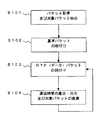
まず、パケット解析装置10では、SW31、32のミラーリング機能により、メディア変換装置20に入出力しているパケットが取得され、取得されたパケットから、さらに対象パケットが抽出される。そして、抽出された対象パケットのうち、RTPパケットについては、入力パケットバッファ部12又は出力パケットバッファ部13に与えられ、送信者レポートパケットについては、RTCP検出部16に与えられる(S101)。
First, in the packet analysis device 10, the packets input / output to / from the
そして、RTCP検出部16では、与えられた送信者レポートパケットからパケット解析に必要な情報が抽出されて、制御処理部15に与えられ、制御処理部15において、メディア変換装置20に入力された基準パケット(例えば、送信者レポートパケット、Iフレームに係るRTPパケット)と、出力された基準パケットとで、対応するものを紐付けする処理が行われる(S102)。
Then, the
なお、ステップS102においては、対象パケットが音声コーデックに係るRTPパケットか、映像コーデックに係るRTPパケットかが判定され、音声コーデックに係るRTPパケットであると判定された場合には、送信者レポートパケットの紐付けの処理が行われる際に、メディア変換装置20における入力側のパケット分割周期と、出力側のパケット分割周期の対応関係も解析される。
In step S102, it is determined whether the target packet is an RTP packet related to an audio codec or an RTP packet related to a video codec. If it is determined that the target packet is an RTP packet related to an audio codec, When the associating process is performed, the correspondence relationship between the input side packet division period and the output side packet division period in the
そして、RTP検出部14では、与えられたRTPパケットからパケット解析に必要な情報が抽出され、制御処理部15に与えられる。そして、制御処理部15では、上述のステップS102における紐付けの結果を利用して、出力パケットバッファ部13に保持されているRTPパケットが、入力パケットバッファ部12に保持されているRTPパケットのうちいずれのRTPパケットと紐付けできるかが検出される(S103)。
Then, the
そして、紐付けされたRTPパケットの取得時間に基づいて、装置内遅延時間が算出されて出力部19により出力され、算出の完了したRTPパケットに係るデータが、入力パケットバッファ部12、出力パケットバッファ部13から廃棄され(S104)、再度上述のステップS103から動作する。
Then, based on the acquisition time of the associated RTP packet, the in-device delay time is calculated and output by the
(A−2−2)RTPパケットの紐付け及び装置内遅延時間の算出について
(イ)変換前と変換後でパケット分割周期が同一の場合
まず、メディア変換装置20のメディア変換において、対象パケットが音声コーデックに係るもので、変換前と変換後のパケット分割周期が同一の場合、すなわち、通信装置41からメディア変換装置20に入力されるパケットの周期と、メディア変換装置20から出力されるパケットの周期が同じ場合において、上述のステップS102〜S104の処理の詳細について説明する。なお、メディア変換装置20における入力側のパケット分割周期と、出力側のパケット分割周期の対応関係は、上述のステップS102において解析されるものである。
(A-2-2) RTP packet linking and intra-device delay time calculation (a) When the packet division period is the same before and after conversion First, in the media conversion of the
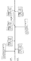
図5は、メディア変換装置20のメディア変換において、変換前と変換後のパケット分割周期が同一の場合に、パケット解析装置10における装置内遅延時間の算出の例について示したタイミングチャートである。
FIG. 5 is a timing chart showing an example of calculation of the in-device delay time in the packet analysis device 10 when the media conversion of the
図5においては、P111〜P113は、入力パケットバッファ部12において保持されているRTPパケットの取得されたタイミング及びそれぞれのRTPパケットに係る内容を示している。P121〜P123は、出力パケットバッファ部13において保持されているRTPパケットの取得されたタイミング及びそれぞれのRTPパケットに係る内容を示している。P131は、メディア変換装置20に入力された送信者レポートパケットが取得されたタイミング及び、その送信者レポートパケットに係る内容を示している。P141は、メディア変換装置20から出力された送信者レポートパケットが取得されたタイミング及び、その送信者レポートパケットに係る内容を示している。
In FIG. 5, P111 to P113 indicate acquisition timings of the RTP packets held in the input
図5の場合においては、上述のステップS102における、制御処理部15による送信者レポートパケットの紐付けとしては、送信者パケットカウント値が同一であるP131とP141が紐付けすると判定される。なお、図5においては、P131のタイムスタンプ値が2567であるため、タイムスタンプ値が2500であるP111とタイムスタンプ値が2600であるP112の間のタイミングで取得したものと判定するようにしても良い。
In the case of FIG. 5, it is determined that P131 and P141 having the same sender packet count value are linked as the link of the sender report packet by the
次に、図5の場合における、上述のステップS103における出力パケットバッファ部13に保持されているパケットと、入力パケットバッファ部12に保持されているRTPパケットの紐付けについて説明する。
Next, the association between the packet held in the output
上述の通り、送信者レポートパケットとして、P131とP141が紐付けできると判定されているので、制御処理部15では、P131とP141を基準として、それ以降のタイミングで取得されたRTPパケットを紐付けできると判定される。すなわち、P131の直後のタイミングで取得されたP112(シーケンス番号:2346)と、P141(シーケンス番号:1236)の直後のタイミングで取得されたP123とが紐付けできると判定される。よって、以降は、入力パケットバッファ部12、出力パケットバッファ部13に保持されるRTPパケットが順次紐付けられる。例えば、入力パケットバッファ部12における、シーケンス番号が2347のRTPパケットと、出力パケットバッファ部13における、シーケンス番号が1237のRTPパケットとが紐付けできると判定できる。上述の例では、基準となる送信者レポートパケットの後のタイミングで取得したRTPパケット同士を紐付けしたが、前のタイミングで取得したRTPパケット同士を紐付けるようにしてもよい。
As described above, since it has been determined that P131 and P141 can be linked as a sender report packet, the
次に、図5の場合における、上述のステップS104における装置内遅延時間の算出方法について説明する。 Next, a method for calculating the in-device delay time in the above-described step S104 in the case of FIG. 5 will be described.
制御処理部15では、上述のステップS103において紐付けされたRTPパケットについて装置内遅延時間が算出される。例えば、上述の通りP112とP123が紐付けられているので、この場合の装置内遅延時間は1.18−1.16=0.02secとなる。
In the
(ロ)変換前と変換後でパケット分割周期が異なる場合
次に、メディア変換装置20のメディア変換において、対象パケットが音声コーデックに係るもので、変換前と変換後のパケット分割周期が異なる場合において、上述のステップS102〜S104の処理の詳細について説明する。なお、メディア変換装置20における入力側のパケット分割周期と、出力側のパケット分割周期の対応関係は、上述のステップS102において解析されるものである。
(B) When the packet division period is different before and after conversion Next, in the media conversion of the
図6は、メディア変換装置20のメディア変換において、変換前と変換後のパケット分割周期が異なる場合に、パケット解析装置10における装置内遅延時間の算出の例について示したタイミングチャートである。図6では、メディア変換装置20の入力側のパケット分割周期は20msecで、出力側のパケット分割周期が40msecであるものとする。すなわち、入力側のRTPパケット1つに対して、出力側のRTPパケットの2つのパケットが対応することになる。
FIG. 6 is a timing chart illustrating an example of calculation of the in-device delay time in the packet analysis device 10 when the media conversion of the
図6においては、P211〜P213は、入力パケットバッファ部12において保持されているRTPパケットの取得されたタイミング及びそれぞれのRTPパケットに係る内容を示している。P221、P222は、出力パケットバッファ部13において保持されているRTPパケットの取得されたタイミング及びそれぞれのRTPパケットに係る内容を示している。P231は、メディア変換装置20に入力された送信者レポートパケットが取得されたタイミング及び、その送信者レポートパケットに係る内容を示している。P241は、メディア変換装置20から出力された送信者レポートパケットが取得されたタイミング及び、その送信者レポートパケットに係る内容を示している。
In FIG. 6, P211 to P213 indicate the timing at which the RTP packets held in the input
図6の場合においては、上述のステップS102における、制御処理部15による送信者レポートパケットの紐付けとしては、P231の送信者パケットカウント値が4で、P241のパケットカウント値が2であるので、2対1の関係にあり、パケット分割周期の最小公倍数の比率と一致するので、P231とP241が紐付けすると判定される。なお、図6においては、P231のタイムスタンプ値が2488であるため、タイムスタンプ値が2500であるP211の前のタイミングで取得したものと判定しても良い。また、P241のタイムスタンプ値が、3768であるため、タイムスタンプ値が3600であるP221と、タイムスタンプ値が3800であるP222の間のタイミングで取得したものと判定しても良い。
In the case of FIG. 6, since the sender report packet is linked by the
次に、図6の場合における、上述のステップS103における出力パケットバッファ部13に保持されているパケットと、入力パケットバッファ部12に保持されているRTPパケットの紐付けについて説明する。
Next, the association of the packet held in the output
上述の通り、送信者レポートパケットとして、P231とP241が紐付けできると判定されているので、制御処理部15では、P231とP241を基準として、それ以降のタイミングで取得されたRTPパケットを紐付けできると判定される。すなわち、P231の直後のタイミングで取得された2つのP211(シーケンス番号:2345)、P212(シーケンス番号:2346)と、P241の直後のタイミングで取得されたP222(シーケンス番号1236)とが紐付けできると判定される。よって、以降は、入力パケットバッファ部12、出力パケットバッファ部13に保持されるRTPパケットが順次紐付けられる。例えば、図示は省略しているが、入力パケットバッファ部12における、シーケンス番号が2347、2348の2つのRTPパケットと、出力パケットバッファ部13における、シーケンス番号が1237のRTPパケットとが紐付けできると判定できる。上述の例では、基準となる送信者レポートパケットの後のタイミングで取得したRTPパケット同士を紐付けしたが、前のタイミングで取得したRTPパケット同士を紐付けるようにしてもよい。
As described above, since it is determined that P231 and P241 can be linked as a sender report packet, the
次に、図6の場合における、上述のステップS104における装置内遅延時間の算出方法について説明する。 Next, a method for calculating the in-device delay time in the above-described step S104 in the case of FIG. 6 will be described.
制御処理部15では、上述のステップS103において紐付けされたRTPパケットについて装置内遅延時間が算出される。例えば、上述の通りP211、P212とP222とが紐付けられているので、この場合の装置内遅延時間は、P212の取得時間と、P222の取得時間とが比較され、1.15−1.16=0.01secとなる。
In the
(ハ)映像コーデックの場合
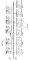
次に、対象パケットが映像コーデックに係るものである場合において、上述のステップS102〜S104の処理の詳細について説明する。なお、メディア変換装置20に入出力されるRTPパケットが映像コーデックに係るものであるか否かは、上述のステップS102において解析されるものである。 図7においては、P311〜P315は、入力パケットバッファ部12において保持されているRTPパケットの取得されたタイミング及びそれぞれのRTPパケットに係る内容を示している。P321〜P326は、出力パケットバッファ部13において保持されているRTPパケットの取得されたタイミング及びそれぞれのRTPパケットに係る内容を示している。
(C) In the case of a video codec Next, when the target packet relates to a video codec, details of the processing in steps S102 to S104 described above will be described. Note that whether or not the RTP packet input / output to / from the
なお、図7においては、メディア変換装置20は、フレーム単位でメディア変換を行い出力するものとする。すなわち、メディア変換装置20では、フレーム一つ分のRTPパケットが入力されると、そのフレームについてメディア変換を行い、変換済のフレームに係るRTPパケットを出力するものとする。
In FIG. 7, the
図7の場合においては、上述のステップS102における、制御処理部15による基準パケット(Iフレームに係るRTPパケット)の紐付けとしては、まず、制御処理部15では、RTP検出部14を介して、入力パケットバッファ部12、出力パケットバッファ部13に保持されているRTPパケットに係る情報(スタートフラグ、マーカフラグなど)が取得され、それぞれのRTPパケットがフレーム単位にグループ化され、さらに、それぞれのフレームについてIフレームであるか否かが検出される。その結果、P311、P312が入力側においてIフレームを構成するRTPパケットであり、P323、P324が、出力側においてIフレームを構成するRTPパケットであったものとする。また、その他にも、入力側において、P313、P314が一つのフレームを構成し、P325、P326も一つのフレームを構成するものと認識される。
In the case of FIG. 7, as the association of the reference packet (the RTP packet related to the I frame) by the
なお、メディア変換装置20は、IフレームのRTPパケットが入力されると、次にIフレームのRTPパケットが入力される前に変換して出力するものとして説明する。そうすると、入力側において、P311、P312で構成されるIフレームが取得された後、入力側において次にIフレームのRTPパケットが取得される前に、出力側において、P323、P324で構成されるIフレームが取得されているため、これらのIフレームに係るRTPパケットは紐付けすることができる。
In the following description, it is assumed that the
次に、図7の場合における、上述のステップS103における出力パケットバッファ部13に保持されているパケットと、入力パケットバッファ部12に保持されているRTPパケットの紐付けについて説明する。
Next, the association between the packet held in the output
上述の通り、P311、P312で構成されるIフレームと、P323、P324で構成されるIフレームが紐付けできると判定されているので、制御処理部15では、これらのIフレームに係るRTPパケットを基準として、それ以降のタイミングで取得されたフレームに係るRTPパケットも紐付けできると判定される。
As described above, since it has been determined that the I frame composed of P311 and P312 and the I frame composed of P323 and P324 can be linked, the
例えば、図7において、入力側において、Iフレームを構成するP312の直後のタイミングで取得されたフレームに係るRTPパケットであるP313、P314の組と、出力側においてIフレームを構成するP324の直後のタイミングで取得されたフレームに係るRTPパケットであるP325、P326の組とが紐付けされることになる。上述の例では、基準となるIフレームに係るRTPパケットの後後のタイミングで取得したフレームに係るRTPパケット同士を紐付けしたが、前のタイミングで取得したフレームに係るRTPパケット同士を紐付けるようにしてもよい。 For example, in FIG. 7, on the input side, a pair of P313 and P314 which are RTP packets related to a frame acquired at a timing immediately after P312 constituting the I frame, and immediately after P324 constituting the I frame on the output side A pair of P325 and P326, which are RTP packets related to the frame acquired at the timing, is linked. In the above example, the RTP packets related to the frame acquired at the later timing of the RTP packet related to the reference I frame are linked, but the RTP packets related to the frame acquired at the previous timing are linked together. It may be.
次に、図7の場合における、上述のステップS104における装置内遅延時間の算出方法について説明する。 Next, a method for calculating the in-device delay time in the above-described step S104 in the case of FIG. 7 will be described.
制御処理部15では、上述のステップS103において紐付けされたRTPパケットについて装置内遅延時間が算出される。例えば、上述の通り入力側のP311、P312と、出力側のP323、P324とが紐付けられているので、この場合の装置内遅延時間は、P312の取得時間と、P323の取得時間とが比較され、1.16−1.15=0.01secとなる。
In the
(A−3)実施形態の効果
この実施形態によれば、以下のような効果を奏することができる。
(A-3) Effects of Embodiment According to this embodiment, the following effects can be achieved.
この実施形態のパケット解析装置10では、まず基準パケットの紐付けを行い(上述の図4のステップS102参照)、基準パケットを目印として、RTPパケットの紐付けを行っている(上述の図4のステップS103参照)。これにより、通信装置41からの通信が開始された後であっても、メディア変換装置20に入出力されるRTPパケットを紐付けし、さらに、装置内遅延時間を算出することができる。
In the packet analysis device 10 of this embodiment, first, the reference packet is linked (see step S102 in FIG. 4 described above), and the RTP packet is linked using the reference packet as a mark (described above in FIG. 4). (See step S103). Thereby, even after the communication from the communication device 41 is started, the RTP packet input / output to / from the
また、パケット解析装置10では、RTP検出部14により、メディア変換装置20に入出力されるRTPパケットの内容を分析し、メディア変換装置20に入出力されるRTPパケットのパケット分割周期を特定している。そして、特定したパケット分割周期を用いて、メディア変換装置20に入出力されるRTPパケットの紐付けをおこなっている(上述の図6参照)。これにより、メディア変換装置20に入出力されるRTPパケットにおいて、入力側と出力側でパケット分割周期が異なる場合であっても、RTPパケットの紐付けを行い、さらに、装置内遅延時間を算出することができる。
In the packet analysis device 10, the
さらに、パケット解析装置10では、RTP検出部14により、メディア変換装置20に入出力されるRTPパケットの内容を分析し、RTPパケットが映像コーデックであると判定した場合には、それぞれRTPパケットにおけるスタートビットとマーカビットを検出し、どのRTPパケットを組として一つのフレームが構成されるのかを検出し、一つのフレームを構成するRTPパケットの組を、Iフレームを基準として、入力側と出力側で紐付けしている(上述の図7参照)。これにより、RTPパケットの内容が映像コーデックであった場合でも、RTPパケットの紐付けを行い、さらに、装置内遅延時間を算出することができる。
Further, in the packet analysis device 10, the
(B)他の実施形態
本発明は、上記の実施形態に限定されるものではなく、以下に例示するような変形実施形態も挙げることができる。
(B) Other Embodiments The present invention is not limited to the above-described embodiments, and may include modified embodiments as exemplified below.
(B−1)上記の実施形態では、パケット解析装置10は、メディア変換装置20に入出力されるRTPパケットを紐付けして、装置内遅延時間を算出するものとして説明したが、装置内遅延時間を算出せずに、RTPパケットの紐付けのみを解析して、その解析結果を、出力部19に出力する装置として構成しても良い。RTPパケットの紐付けの解析結果を用いて、例えば、メディア変換装置20によるRTPパケットの処理前と処理後を比較し、メディア変換装置20によるメディア変換が正しく行われているかなど、メディア変換装置20の動作を分析することに用いることができる。
(B-1) In the above embodiment, the packet analysis device 10 has been described as linking RTP packets input / output to / from the
(B−2)上記の実施形態では、パケット解析装置10は、RTCPパケットの紐付けを行い(上述の図4のステップS102参照)、RTCPパケットを目印として、RTPパケットの紐付けを行う例(上述の図4のステップS103参照)について説明しているが、パケット解析に係るプロトコルは、RTCPとRTPの組み合わせに限定されないものである。例えば、定期もしくは不定期の間隔で、送信側通信装置(通信装置41)から受信側通信装置(通信装置42)へ向けて、RTCP以外の通信制御情報が挿入された通信制御パケットが送出される場合には、その通信制御パケットを紐付けし、それを目印として、送信側通信装置(通信装置41)から受信側通信装置(通信装置42)へ向けて送出される、RTP以外のデータが挿入されたデータパケットを入力側と出力側で紐付けするようにしても良い。 (B-2) In the above embodiment, the packet analysis apparatus 10 associates RTCP packets (see step S102 in FIG. 4 above), and associates RTP packets using the RTCP packet as a mark ( The above-described protocol (see step S103 in FIG. 4) is described, but the protocol for packet analysis is not limited to the combination of RTCP and RTP. For example, a communication control packet in which communication control information other than RTCP is inserted is transmitted from the transmission side communication device (communication device 41) to the reception side communication device (communication device 42) at regular or irregular intervals. In this case, the communication control packet is linked, and data other than RTP that is sent from the transmission side communication device (communication device 41) to the reception side communication device (communication device 42) is inserted as a mark. It is also possible to associate the data packets that are made on the input side and the output side.
(B−3)上記の実施形態では、パケット解析装置10は、メディア変換装置20において入出力されるパケットについて解析を行っているが、解析を行う対象は、メディア変換装置20に入出力されるパケットに限定されず、例えば、パケット暗号化装置やプロキシーサーバなど、送信側通信装置(通信装置41)から送出されたパケットに何らかの処理を施して、受信側通信装置(通信装置42)に向けて送出する他の装置(以下、「パケット処理装置」という)に適用しても良い。
(B-3) In the above embodiment, the packet analysis device 10 analyzes the packet input / output in the
(B−4)上記の実施形態において、制御処理部15は、RTCP検出部16が検出した送信者レポートパケットのデータを入力側と出力側で両方保持するようにしているが、入力側の送信者レポートパケットに係るデータだけを保持して、紐付けできる送信者レポートパケットが出力側に発生した場合に、入力側と出力側の送信者レポートパケットのタイミングの検出をするようにしても良い。
(B-4) In the above embodiment, the
(B−5)上記の実施形態においては、パケット解析装置10は、RTPパケットが映像コーデックと、音声コーデックの両方に対応するものとして記載しているが、いずれか一方のみに対応するようにしても良い。パケット解析装置10が、映像コーデックのみに対応する場合には、データベース部17や、RTCP検出部16、その他RTCPパケットに係る処理を行う構成を省略するようにしても良い。
(B-5) In the above embodiment, the packet analysis device 10 describes that the RTP packet corresponds to both the video codec and the audio codec. However, the packet analysis device 10 supports only one of them. Also good. When the packet analysis device 10 supports only the video codec, the
(B−6)上記の実施形態において、送信者レポートパケットを取得したタイミングの検出については、送信者レポートパケットのRTPタイムスタンプ値と、RTPパケットのタイムスタンプ値を比較することにより検出している(上述の図5、図6参照)が、送信者レポートパケットについても取得時間を計時しておいて、RTPパケットの取得時間と比較することにより検出するようにしても良い。 (B-6) In the above embodiment, the timing at which the sender report packet is acquired is detected by comparing the RTP timestamp value of the sender report packet with the timestamp value of the RTP packet. (See FIGS. 5 and 6 above), the sender report packet may also be detected by measuring the acquisition time and comparing it with the acquisition time of the RTP packet.
1…通信システム、10…パケット解析装置、11…フィルタ部、12…入力パケットバッファ部、13…出力パケットバッファ部、14…RTP検出部、15…制御処理部、16…RTCP検出部、17…データベース部、18…解析対象登録部、19…出力部、20…メディア変換装置、31、32…SW、N1、N2…ネットワーク、41、42…通信装置。
DESCRIPTION OF
Claims (6)
上記第1の通信装置から上記パケット処理装置に入力された、データが挿入された入力データパケットと、上記パケット処理装置から上記第2の通信装置に向けて送出された、データが挿入された出力データパケットとを保持するデータパケット保持手段と、
上記第1の通信装置から上記パケット処理装置に入力された、所定の種類のパケットである入力基準パケットと、上記パケット処理装置から上記第2の通信装置に向けて送出された、所定の種類のパケットである出力基準パケットについて、上記パケット処理装置による処理前と処理後で対応する組を特定する基準パケット対応特定手段と、
少なくとも、上記基準パケット対応特定手段により対応付けを特定された、入力基準パケットが上記パケット処理装置に入力されたタイミングと、出力基準パケットが上記パケット処理装置から出力されたタイミングとに基づいて、上記データパケット保持手段に保持されている、入力データパケット及び出力データパケットについて上記パケット処理装置による処理前と処理後で対応する組を特定するデータパケット対応特定手段と
を有することを特徴とするパケット解析装置。 Packet analysis for processing packets sent from the first communication device to the second communication device and performing analysis on packets input to and output from the packet processing device sent to the second communication device In the device
An input data packet into which data is inserted, which is input from the first communication device to the packet processing device, and an output into which data is inserted, which is sent from the packet processing device to the second communication device. Data packet holding means for holding data packets;
An input reference packet that is a predetermined type of packet input from the first communication device to the packet processing device, and a predetermined type of packet that is transmitted from the packet processing device toward the second communication device. A reference packet correspondence specifying means for specifying a pair corresponding to an output reference packet that is a packet before and after processing by the packet processing device;
Based on at least the timing at which the input reference packet is input to the packet processing device and the timing at which the output reference packet is output from the packet processing device. Packet analysis comprising: data packet correspondence specifying means for specifying a pair corresponding to the input data packet and the output data packet held by the data packet holding means before and after processing by the packet processing device. apparatus.
入力基準パケット及び出力基準パケットは、所定の種類の映像フレームに係るデータが挿入されたパケットであることを特徴とする請求項1または2に記載のパケット解析装置。 The packet processing apparatus processes a video packet for each video frame,
3. The packet analysis device according to claim 1, wherein the input reference packet and the output reference packet are packets into which data relating to a predetermined type of video frame is inserted.
上記第1の通信装置から上記パケット処理装置に入力された、データが挿入された入力データパケットと、上記パケット処理装置から上記第2の通信装置に向けて送出された、データが挿入された出力データパケットとを保持するデータパケット保持手段と、
上記第1の通信装置から上記パケット処理装置に入力された、所定の種類のパケットである入力基準パケットと、上記パケット処理装置から上記第2の通信装置に向けて送出された、所定の種類のパケットである出力基準パケットについて、上記パケット処理装置による処理前と処理後で対応する組を特定する基準パケット対応特定手段と、
少なくとも、上記基準パケット対応特定手段により対応付けを特定された、入力基準パケットが上記パケット処理装置に入力されたタイミングと、出力基準パケットが上記パケット処理装置から出力されたタイミングとに基づいて、上記データパケット保持手段に保持されている、入力データパケット及び出力データパケットについて上記パケット処理装置による処理前と処理後で対応する組を特定するデータパケット対応特定手段と
して機能させることを特徴とするパケット解析プログラム。 Packet analysis for processing packets sent from the first communication device to the second communication device and performing analysis on packets input to and output from the packet processing device sent to the second communication device The computer installed in the device
An input data packet into which data is inserted, which is input from the first communication device to the packet processing device, and an output into which data is inserted, which is sent from the packet processing device to the second communication device. Data packet holding means for holding data packets;
An input reference packet that is a predetermined type of packet input from the first communication device to the packet processing device, and a predetermined type of packet that is transmitted from the packet processing device toward the second communication device. A reference packet correspondence specifying means for specifying a pair corresponding to an output reference packet that is a packet before and after processing by the packet processing device;
Based on at least the timing at which the input reference packet is input to the packet processing device and the timing at which the output reference packet is output from the packet processing device. It is made to function as a data packet correspondence specifying means for specifying a pair corresponding to an input data packet and an output data packet held in the data packet holding means before and after processing by the packet processing device. Packet analysis program.
データパケット保持手段、基準パケット対応特定手段、データパケット対応特定手段を有し、
上記データパケット保持手段は、上記第1の通信装置から上記パケット処理装置に入力された、データが挿入された入力データパケットと、上記パケット処理装置から上記第2の通信装置に向けて送出された、データが挿入された出力データパケットとを保持し、
上記基準パケット対応特定手段は、上記第1の通信装置から上記パケット処理装置に入力された、所定の種類のパケットである入力基準パケットと、上記パケット処理装置から上記第2の通信装置に向けて送出された、所定の種類のパケットである出力基準パケットについて、上記パケット処理装置による処理前と処理後で対応する組を特定し、
上記データパケット対応特定手段は、少なくとも、上記基準パケット対応特定手段により対応付けを特定された、入力基準パケットが上記パケット処理装置に入力されたタイミングと、出力基準パケットが上記パケット処理装置から出力されたタイミングとに基づいて、上記データパケット保持手段に保持されている、入力データパケット及び出力データパケットについて上記パケット処理装置による処理前と処理後で対応する組を特定する
ことを特徴とするパケット解析方法。 Packet analysis for processing packets sent from the first communication device to the second communication device and performing analysis on packets input to and output from the packet processing device sent to the second communication device In the method
Data packet holding means, reference packet correspondence specifying means, data packet correspondence specifying means,
The data packet holding means is input from the first communication device to the packet processing device, the input data packet into which data is inserted, and sent from the packet processing device to the second communication device. Hold the output data packet with the data inserted,
The reference packet correspondence specifying unit is configured to input a reference packet that is a predetermined type of packet input from the first communication device to the packet processing device, and from the packet processing device to the second communication device. For the output reference packet, which is a predetermined type of packet that has been sent out, identify a pair corresponding to before and after processing by the packet processing device,
The data packet correspondence specifying means includes at least the timing at which the input reference packet is input to the packet processing apparatus, the output of which is specified by the reference packet correspondence specifying means, and the output reference packet is output from the packet processing apparatus. A packet analysis unit for identifying a pair corresponding to the input data packet and the output data packet held by the data packet holding unit before and after the processing by the packet processing device based on the received timing Method.
Priority Applications (1)
| Application Number | Priority Date | Filing Date | Title |
|---|---|---|---|
| JP2008250478A JP4683107B2 (en) | 2008-09-29 | 2008-09-29 | Packet analysis apparatus, program, and method |
Applications Claiming Priority (1)
| Application Number | Priority Date | Filing Date | Title |
|---|---|---|---|
| JP2008250478A JP4683107B2 (en) | 2008-09-29 | 2008-09-29 | Packet analysis apparatus, program, and method |
Publications (2)
| Publication Number | Publication Date |
|---|---|
| JP2010081534A true JP2010081534A (en) | 2010-04-08 |
| JP4683107B2 JP4683107B2 (en) | 2011-05-11 |
Family
ID=42211412
Family Applications (1)
| Application Number | Title | Priority Date | Filing Date |
|---|---|---|---|
| JP2008250478A Active JP4683107B2 (en) | 2008-09-29 | 2008-09-29 | Packet analysis apparatus, program, and method |
Country Status (1)
| Country | Link |
|---|---|
| JP (1) | JP4683107B2 (en) |
Cited By (1)
| Publication number | Priority date | Publication date | Assignee | Title |
|---|---|---|---|---|
| JP2014086904A (en) * | 2012-10-24 | 2014-05-12 | Oki Electric Ind Co Ltd | Communication quality measurement system and method |
Citations (7)
| Publication number | Priority date | Publication date | Assignee | Title |
|---|---|---|---|---|
| JPH09261254A (en) * | 1996-01-29 | 1997-10-03 | Hewlett Packard Co <Hp> | Method and instrument for measuring service quality |
| JP2001016267A (en) * | 1999-07-01 | 2001-01-19 | Sony Corp | Communication equipment and method and medium |
| JP2002281076A (en) * | 2001-03-15 | 2002-09-27 | Oki Electric Ind Co Ltd | Fluctuation absorbing device |
| JP2002300200A (en) * | 2001-03-30 | 2002-10-11 | Oki Electric Ind Co Ltd | Fluctuation absorbing device for absorbing fluctuation among packet reception interval |
| JP2006277518A (en) * | 2005-03-30 | 2006-10-12 | Nomura Research Institute Ltd | Log acquisition program and method |
| JP2007329534A (en) * | 2006-06-06 | 2007-12-20 | Matsushita Electric Ind Co Ltd | Audio transmission system |
| JP2008061271A (en) * | 2007-10-01 | 2008-03-13 | Ntt Data Corp | Packet tracing method and packet tracing program |
-
2008
- 2008-09-29 JP JP2008250478A patent/JP4683107B2/en active Active
Patent Citations (7)
| Publication number | Priority date | Publication date | Assignee | Title |
|---|---|---|---|---|
| JPH09261254A (en) * | 1996-01-29 | 1997-10-03 | Hewlett Packard Co <Hp> | Method and instrument for measuring service quality |
| JP2001016267A (en) * | 1999-07-01 | 2001-01-19 | Sony Corp | Communication equipment and method and medium |
| JP2002281076A (en) * | 2001-03-15 | 2002-09-27 | Oki Electric Ind Co Ltd | Fluctuation absorbing device |
| JP2002300200A (en) * | 2001-03-30 | 2002-10-11 | Oki Electric Ind Co Ltd | Fluctuation absorbing device for absorbing fluctuation among packet reception interval |
| JP2006277518A (en) * | 2005-03-30 | 2006-10-12 | Nomura Research Institute Ltd | Log acquisition program and method |
| JP2007329534A (en) * | 2006-06-06 | 2007-12-20 | Matsushita Electric Ind Co Ltd | Audio transmission system |
| JP2008061271A (en) * | 2007-10-01 | 2008-03-13 | Ntt Data Corp | Packet tracing method and packet tracing program |
Cited By (1)
| Publication number | Priority date | Publication date | Assignee | Title |
|---|---|---|---|---|
| JP2014086904A (en) * | 2012-10-24 | 2014-05-12 | Oki Electric Ind Co Ltd | Communication quality measurement system and method |
Also Published As
| Publication number | Publication date |
|---|---|
| JP4683107B2 (en) | 2011-05-11 |
Similar Documents
| Publication | Publication Date | Title |
|---|---|---|
| US8023419B2 (en) | Remote monitoring of real-time internet protocol media streams | |
| US7886071B2 (en) | Communication processing device, communication control method, and computer program | |
| US9137168B2 (en) | Method, device and system for packet transmission over IP networks | |
| US9253063B2 (en) | Bi-directional video compression for real-time video streams during transport in a packet switched network | |
| WO2020006912A1 (en) | Method and device for analyzing network transmission quality, computer equipment and storage medium | |
| JP6743192B2 (en) | Video service quality evaluation method and apparatus | |
| EP2086174A1 (en) | A method and system of multimedia service performance monitoring | |
| JP2001320422A (en) | Method and apparatus for packet transmission attended with header compression | |
| WO2017206767A1 (en) | Method for diagnosing voice delay, gateway device, and computer storage medium | |
| KR100793345B1 (en) | Apparatus and method of processing packet in system for voice and data combined | |
| JP4600513B2 (en) | Data transmission apparatus, transmission rate control method, and program | |
| KR20140123753A (en) | Method and apparatus for schduling video traffic in wireless communication system | |
| JP4683107B2 (en) | Packet analysis apparatus, program, and method | |
| CN101741752B (en) | The methods, devices and systems of video streaming | |
| JP5311460B2 (en) | Connection control device | |
| JP5535231B2 (en) | Reception processing apparatus and program | |
| US7894486B2 (en) | Method for depacketization of multimedia packet data | |
| JP2009188674A (en) | Transmitting apparatus, receiving apparatus, moving image sound transmission quality evaluating method, and moving image sound transmission quality evaluation program | |
| JP2002314595A (en) | Communication repeater and jitter suppression method | |
| JP2013051565A (en) | Communication terminal device, communication control method, and communication control program | |
| JP2007208418A (en) | Inspection information generating apparatus, transmitter, and relaying apparatus | |
| KR101098826B1 (en) | Method and apparatus for providing video streaming scheduling | |
| JP2003023462A (en) | Retransmission method for multipoint broadcast communication network | |
| JP2008141633A (en) | Data communication system, data-receiving apparatus and method, and data transmitting apparatus and method | |
| JP5066538B2 (en) | Packet relay apparatus and packet relay method |
Legal Events
| Date | Code | Title | Description |
|---|---|---|---|
| A977 | Report on retrieval |
Free format text: JAPANESE INTERMEDIATE CODE: A971007 Effective date: 20100806 |
|
| A131 | Notification of reasons for refusal |
Free format text: JAPANESE INTERMEDIATE CODE: A131 Effective date: 20100817 |
|
| A521 | Written amendment |
Free format text: JAPANESE INTERMEDIATE CODE: A523 Effective date: 20101018 |
|
| TRDD | Decision of grant or rejection written | ||
| A01 | Written decision to grant a patent or to grant a registration (utility model) |
Free format text: JAPANESE INTERMEDIATE CODE: A01 Effective date: 20110111 |
|
| A01 | Written decision to grant a patent or to grant a registration (utility model) |
Free format text: JAPANESE INTERMEDIATE CODE: A01 |
|
| A61 | First payment of annual fees (during grant procedure) |
Free format text: JAPANESE INTERMEDIATE CODE: A61 Effective date: 20110124 |
|
| FPAY | Renewal fee payment (event date is renewal date of database) |
Free format text: PAYMENT UNTIL: 20140218 Year of fee payment: 3 |
|
| R150 | Certificate of patent or registration of utility model |
Ref document number: 4683107 Country of ref document: JP Free format text: JAPANESE INTERMEDIATE CODE: R150 Free format text: JAPANESE INTERMEDIATE CODE: R150 |
|
| FPAY | Renewal fee payment (event date is renewal date of database) |
Free format text: PAYMENT UNTIL: 20140218 Year of fee payment: 3 |
|
| S531 | Written request for registration of change of domicile |
Free format text: JAPANESE INTERMEDIATE CODE: R313531 |
|
| FPAY | Renewal fee payment (event date is renewal date of database) |
Free format text: PAYMENT UNTIL: 20140218 Year of fee payment: 3 |
|
| R350 | Written notification of registration of transfer |
Free format text: JAPANESE INTERMEDIATE CODE: R350 |