JP2010081410A - Wireless device and antenna device - Google Patents
Wireless device and antenna device Download PDFInfo
- Publication number
- JP2010081410A JP2010081410A JP2008248960A JP2008248960A JP2010081410A JP 2010081410 A JP2010081410 A JP 2010081410A JP 2008248960 A JP2008248960 A JP 2008248960A JP 2008248960 A JP2008248960 A JP 2008248960A JP 2010081410 A JP2010081410 A JP 2010081410A
- Authority
- JP
- Japan
- Prior art keywords
- shaft member
- housing
- antenna
- casing
- conductor
- Prior art date
- Legal status (The legal status is an assumption and is not a legal conclusion. Google has not performed a legal analysis and makes no representation as to the accuracy of the status listed.)
- Granted
Links
Images


Classifications
-
- H—ELECTRICITY
- H01—ELECTRIC ELEMENTS
- H01Q—ANTENNAS, i.e. RADIO AERIALS
- H01Q1/00—Details of, or arrangements associated with, antennas
- H01Q1/12—Supports; Mounting means
- H01Q1/22—Supports; Mounting means by structural association with other equipment or articles
- H01Q1/24—Supports; Mounting means by structural association with other equipment or articles with receiving set
- H01Q1/241—Supports; Mounting means by structural association with other equipment or articles with receiving set used in mobile communications, e.g. GSM
- H01Q1/242—Supports; Mounting means by structural association with other equipment or articles with receiving set used in mobile communications, e.g. GSM specially adapted for hand-held use
- H01Q1/243—Supports; Mounting means by structural association with other equipment or articles with receiving set used in mobile communications, e.g. GSM specially adapted for hand-held use with built-in antennas
-
- H—ELECTRICITY
- H01—ELECTRIC ELEMENTS
- H01Q—ANTENNAS, i.e. RADIO AERIALS
- H01Q7/00—Loop antennas with a substantially uniform current distribution around the loop and having a directional radiation pattern in a plane perpendicular to the plane of the loop
-
- H—ELECTRICITY
- H01—ELECTRIC ELEMENTS
- H01Q—ANTENNAS, i.e. RADIO AERIALS
- H01Q7/00—Loop antennas with a substantially uniform current distribution around the loop and having a directional radiation pattern in a plane perpendicular to the plane of the loop
- H01Q7/06—Loop antennas with a substantially uniform current distribution around the loop and having a directional radiation pattern in a plane perpendicular to the plane of the loop with core of ferromagnetic material
- H01Q7/08—Ferrite rod or like elongated core
-
- H—ELECTRICITY
- H04—ELECTRIC COMMUNICATION TECHNIQUE
- H04M—TELEPHONIC COMMUNICATION
- H04M1/00—Substation equipment, e.g. for use by subscribers
- H04M1/02—Constructional features of telephone sets
- H04M1/0202—Portable telephone sets, e.g. cordless phones, mobile phones or bar type handsets
- H04M1/0206—Portable telephones comprising a plurality of mechanically joined movable body parts, e.g. hinged housings
- H04M1/0208—Portable telephones comprising a plurality of mechanically joined movable body parts, e.g. hinged housings characterized by the relative motions of the body parts
- H04M1/0214—Foldable telephones, i.e. with body parts pivoting to an open position around an axis parallel to the plane they define in closed position
- H04M1/0216—Foldable in one direction, i.e. using a one degree of freedom hinge
Abstract
Description
本発明は無線装置及びアンテナ装置に係り、特に2以上の筐体が相互に回動可能に連結されて構成された無線装置及び該無線装置用のアンテナ装置に関する。 The present invention relates to a wireless device and an antenna device, and more particularly, to a wireless device configured by two or more casings being rotatably connected to each other, and an antenna device for the wireless device.
近年の携帯電話機等の無線装置は、多機能、高性能化と小型、薄型化の要求を両立させるため、2筐体が開閉可能に連結されて構成されたものが主流を占めている。2筐体の接続には、折りたたみ型、2軸ヒンジを備えた折りたたみ型(スウィーベル型ともいう。)、スライド型等の方式が用いられている。これらのうち折りたたみ型及びスウィーベル型はヒンジ部を備え、2筐体が該ヒンジ部を介して相互に回動可能に連結されて構成される。 2. Description of the Related Art In recent years, wireless devices such as mobile phones are mainly composed of two casings that are connected to be openable and closable in order to satisfy the demands for multi-function, high performance, small size, and thinning. For the connection of the two housings, a folding type (also called a swivel type) having a biaxial hinge, a sliding type, or the like is used. Of these, the folding type and the swivel type are provided with a hinge portion, and two casings are connected to each other via the hinge portion so as to be rotatable.
一方、携帯電話機等の無線装置用のアンテナ装置は、従来の筐体外部に延伸されて使用されるホイップアンテナ等のタイプに代わって、筐体に内蔵されたタイプが主流である。このような筐体内蔵タイプのアンテナ装置を使用することにより、無線装置のデザイン性や操作性を向上させることができる。しかし、上述したように無線装置の多機能、高性能化と小型、薄型化が共に要求されることから、アンテナ装置は筐体内部の限定されたスペースに実装された状態で所要の性能を発揮しなければならないという課題の解決を求められている。 On the other hand, an antenna device for a wireless device such as a cellular phone is mainly a type that is built in a case instead of a conventional type such as a whip antenna that is extended outside the case. By using such a housing-embedded antenna device, the design and operability of the wireless device can be improved. However, as described above, since the multi-function, high performance, small size, and thinness of the wireless device are required, the antenna device exhibits the required performance when mounted in a limited space inside the housing. There is a need to solve the problem that must be done.
上述した課題を解決することを目的として、従来、ヒンジ部にアンテナを配設して構成された携帯無線機が知られている(例えば、特許文献1参照。)。上記の特許文献1に記載された携帯無線機は、第1の筐体と第2の筐体がヒンジ部により回動自在に連結されて構成される。該ヒンジ部に、ヒンジ軸を構成するヒンジコアが配設されている。
In order to solve the above-described problem, a portable wireless device configured by arranging an antenna in a hinge portion has been known (for example, see Patent Document 1). The portable wireless device described in
特許文献1によれば、上記のヒンジコアは、第2の筐体に機械的に固定されると共に第2の筐体の回路基板と電気的接続された第1部材と、第1の筐体に機械的に固定されているが第1の筐体の回路基板と電気的に未接続の第2部材が連結されて構成される。第1部材と第2部材は金属等の導電性部材により略円筒形状または略円柱形状に形成されている。このような構成により、上記のヒンジコアは、第1の筐体の回路基板とは非導通の状態で第2の筐体の回路基板からアンテナ素子として給電される。
上述した特許文献1に開示された携帯無線機は、ヒンジ軸を構成するヒンジコアの全部を導電性部材で構成し、アンテナ素子として給電するものである。特許文献1の明細書の段落「0026」の記載によれば、該ヒンジコアは金属等の導電性部材により略円筒形状または略円柱形状に形成され、互いに回動する第2の筐体側の第1部材と第1の筐体側の第2部材が機械的に連結接続された構造を有する。該ヒンジコアは、所定の回動位置でクリック感が得られるように保持力を発生する機構と、自力で回動する回転力を発生する機構とを有している。
The portable wireless device disclosed in
上記の「自力で回動する回転力を発生する機構」として、例えば回動軸の方向にスプリングを配設して回転抵抗を付加することが考えられる。スプリングは一般に金属製であって導電性を有し、2筐体相互の回動による開閉の状態(例えば折りたたみ型携帯電話における2筐体の開きの角度)によって形状が変化するとアンテナ特性にも影響する。開閉の状態は無線装置の利用目的に応じて変化することが普通であるから、上記のアンテナ特性への影響は好ましくないという問題がある。 As the above-mentioned “mechanism for generating a rotational force that rotates by itself”, for example, it is conceivable to provide a rotational resistance by arranging a spring in the direction of the rotational axis. The spring is generally made of metal and has electrical conductivity. When the shape of the spring changes depending on the opening and closing of the two casings (for example, the opening angle of the two casings in a foldable mobile phone), the antenna characteristics are also affected. To do. Since the state of opening and closing usually changes according to the purpose of use of the wireless device, there is a problem that the influence on the antenna characteristics is not preferable.
本発明は上記問題を解決するためになされたもので、2筐体を連結するヒンジ部の部材を利用して構成されたアンテナ装置の特性が、2筐体の回動による開閉の状態の影響を受けにくいようにすることを目的とする。 The present invention has been made to solve the above problems, and the characteristics of an antenna device configured by using a member of a hinge portion that connects two housings is affected by the state of opening and closing due to the rotation of the two housings. The purpose is to make it difficult to receive.
上記目的を達成するために、本発明の無線装置は、第1の筐体と、前記第1の筐体に対して回動可能に連結され、アンテナ給電回路及び接地導体部を内蔵してなる第2の筐体と、前記第2の筐体に固定されると共に導電性の部分を有してなる軸部材が、前記第1の筐体に固定されてなる軸受け部材に挿通されて前記第2の筐体の前記第1の筐体に対する回動の軸をなし、かつ、前記導電性の部分が前記アンテナ給電回路に接続されてなるヒンジ部とを備えたことを特徴とする。 In order to achieve the above object, a wireless device of the present invention is connected to a first housing and a first housing so as to be rotatable, and includes an antenna feeding circuit and a ground conductor. A shaft member, which is fixed to the second housing and fixed to the second housing and has a conductive portion, is inserted through a bearing member fixed to the first housing, and is And a hinge portion that forms an axis of rotation of the second housing with respect to the first housing, and the conductive portion is connected to the antenna feeding circuit.
また、本発明のアンテナ装置は、第1の筐体と第2の筐体が相互に回動可能に連結されて構成された無線装置用のアンテナ装置において、前記第2の筐体に固定されて導電性の部分を有する軸部材が前記第1の筐体に固定された軸受け部材に挿通され、かつ、前記軸部材の導電性の部分が前記第2の筐体に配設された基板の有するアンテナ給電回路に接続されてアンテナ素子を構成したことを特徴とする。 The antenna device according to the present invention is fixed to the second housing in an antenna device for a wireless device configured such that a first housing and a second housing are connected to each other so as to be rotatable. A shaft member having a conductive portion is inserted through a bearing member fixed to the first housing, and the conductive portion of the shaft member is disposed on the second housing. The antenna element is configured by being connected to an antenna feeding circuit having the antenna element.
本発明によれば、2筐体を連結するヒンジ部を構成する軸部材と軸受け部材が一方と他方の筐体にそれぞれ固定されている点に着目し、軸部材の導電性の部分をアンテナ素子として利用することにより、ヒンジ部の部材を利用して構成されたアンテナ装置の特性が2筐体相互の回動による開閉の状態の影響を受けにくいようにすることができる。 According to the present invention, paying attention to the fact that the shaft member and the bearing member constituting the hinge portion connecting the two housings are respectively fixed to the one housing and the other housing, the conductive portion of the shaft member is the antenna element. As a result, it is possible to make the characteristics of the antenna device configured using the member of the hinge part less susceptible to the open / close state due to the mutual rotation of the two housings.
以下、図面を参照して本発明の実施例を説明する。なお以下の各図を参照しながら上下左右又は水平、垂直(鉛直)をいうときは、特に断らない限り、図が表された紙面における上下左右又は水平、垂直(鉛直)を意味するものとする。また、各図の間で同一の符号は、同一の構成を表すものとする。 Embodiments of the present invention will be described below with reference to the drawings. In addition, when referring to the following figures, up / down / left / right or horizontal / vertical (vertical) means up / down / left / right / horizontal / vertical (vertical) on the paper on which the figure is represented unless otherwise specified. . Moreover, the same code | symbol shall represent the same structure between each figure.
以下、図1ないし図11を参照して、本発明の実施例1を説明する。図1は、本発明の実施例1に係る無線装置である携帯通信端末1の構成を表す図である。携帯通信端末1は、第1筐体11と第2筐体12がヒンジ部13を介して開閉可能に接続されることにより構成されている。図1における左斜め上方が、携帯通信端末1の使用時の正面方向に相当する。
第1筐体11と第2筐体12の開閉の形式は、折りたたみ式、2軸ヒンジ(スウィーベル)式等が考えられるが、これらに限るものではない。ヒンジ部13は、第1筐体11と第2筐体12の間に位置して相互に開閉可能とする機構を内蔵する部分を指し、図1においては破線の楕円で囲んで表している。
As a form of opening and closing of the
第1筐体11の正面側には、例えば液晶デバイスからなる表示部が設けられている(第1筐体11又は第2筐体12の背面をはじめとする他の面に、別の表示部が設けられていてもよい。)。第2筐体12の正面側には、複数の操作キーからなる操作部が設けられている(操作キーの一部は、第1筐体11又は第2筐体12の側面をはじめとする他の面に設けられてもよい。)。
A display unit made of, for example, a liquid crystal device is provided on the front side of the first housing 11 (another display unit is provided on another surface such as the back surface of the
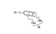
図2は、ヒンジ部13の構成を表す図である。ヒンジ部13の第2筐体12側の一部は、曲線状のブロック矢印で示すように、軸部材15を収容している。軸部材15は、例えば金属材料をシャフト状に形成したものとするが、一部を金属材料で形成し他の部分を非導電性の材料で形成したものでもよい。ヒンジ部13の第1筐体11側の一部は、曲線状のブロック矢印で示すように、軸受け部材16を収容している。軸受け部材16は、カバー部16aとヘッド部16bからなる。
FIG. 2 is a diagram illustrating the configuration of the
軸部材15は、軸受け部材16に向かうブロック矢印で示すように、中空の円筒状に形成された軸受け部材16に挿通される。図3は軸部材15と軸受け部材16の構造的関係、すなわち軸部材15が軸受け部材16に挿通された状態を表す図である。軸部材15は、第2筐体12に対して機械的に固定されている。軸受け部材16は、第1筐体11に対して機械的に固定されている。このような構造によって、第2筐体12は第1筐体11に対して軸部材15がなす軸の周りに回動することができる。
The
図4に示すように、カバー部16aの中空の円筒状に形成された内壁に相当する部分にスプリング17(螺旋状の点線で示す。図2及び図3では煩雑を避けるため図示を省略したもの。)が取り付けられている。スプリング17の作用によって上記の回動における回転抵抗が付与され、例えば第1筐体11及び第2筐体12を相互に閉じるときに適度な抵抗感を与えたり、相互に開くときにある程度自然に開くような操作感を持たせたりすることができる。カバー部16aは、第1筐体11及び第2筐体12の相互の開閉操作に適度なクリック感を付与することができる機構を備えてもよい。
As shown in FIG. 4, a spring 17 (indicated by a spiral dotted line in the portion corresponding to the hollow cylindrical inner wall of the
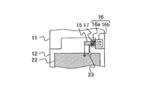
図5は、軸部材15の電気的接続を表す図である。図2を参照して説明したように、軸受け部材16はヒンジ部13の第1筐体11側の一部の内側に配設され(図5では軸受け部材16を点線で表す。)、第1筐体11に対して機械的に固定されている。また、軸部材15はヒンジ部13の第2筐体12側の一部の内側に配設され(図5では軸部材15を点線で表す。)、第2筐体12に対して機械的に固定されている。
FIG. 5 is a diagram illustrating electrical connection of the
第1筐体11及び第2筐体12は、それぞれ、第1基板(図5には図示せず。)及び第2基板22(図5に破線で示す。)を内蔵している。第2基板22には、シンボルで表したアンテナ給電回路23と、図示しない接地導体部が設けられている。金属材料で形成された軸部材15がアンテナ給電回路23に接続されてアンテナ素子として励振されることにより、携帯通信端末1用のアンテナ装置を構成する。
The
携帯通信端末1又はそのアンテナ装置の上述した構成により、以下に挙げる効果が得られる。まず図5に示すように、軸受け部15をアンテナ素子に用いたアンテナ装置をヒンジ部13の右端に寄せて配設することにより、ヒンジ部13の左側のスペースに例えば他のアンテナ装置を配設することができ、実装スペースの効率的利用が可能になる。
The following effects can be obtained by the above-described configuration of the
次に、アンテナ素子として励振される軸部材15は第2筐体12に対して機械的に固定されているので、第2筐体12の第1筐体11に対する回動によって形状が変化することがなく、安定したアンテナ特性を得ることができる。
Next, since the
さらに、一定の範囲で軸受け部材16のサイズに関わらず軸部材15の回動軸方向の長さを選ぶことができる(例えば図5において、軸部材15を左方に延伸する(すなわち、軸部材15の少なくとも一部を軸受け部材16の外側に露出させる。なおここでいう「露出」は、携帯通信端末1の外側から見えることを意味しない。)ことが可能である。)ので、一定の範囲でヒンジ部13の大型化を招かずにアンテナ素子の共振周波数を選ぶことができる。
Further, the length of the
上記のように軸部材15の少なくとも一部を軸受け部材16の外側に露出させることによって、該露出させた一部の接続又は形状等についていくつかの変形例を構成することができる。図6は、実施例1のそのような第1の変形例の電気的接続を、図1、図2又は図5における携帯通信端末1の使用時の正面方向から見て表す図である。図6において、図2ないし図5に表した各構成と同じ構成には同じ符号を付して表し、説明を省略する。
By exposing at least a part of the
図6に示すように、軸部材15のうち軸受け部材16の外側に露出した部分は、1箇所においてアンテナ給電回路23に接続されるのに加えて別の箇所において基板22の図示しない接地導体部に短絡される。このような接続によっていわゆる逆F型アンテナを構成し、給電箇所23から見たインピーダンスを調整することができる。
As shown in FIG. 6, the portion of the
図7は、実施例1の第2の変形例における軸部材15の形状を表す三面図である。三面図のうち右下の図は、図1、図2又は図5における左斜め上方(携帯通信端末1の使用時の正面方向)から見て表した正面図である。該正面図における左側の部分は、図3又は図5において軸受け部材16の外側に露出した部分である。第2の変形例においては、当該露出部分の断面を半円状に形成している。
FIG. 7 is a three-view diagram illustrating the shape of the
このように形成することによって、上記の正面図にブロック矢印で示すように、下方向(基板22の方向)から例えば接続用のピンを立てて軸部材15に接続することが容易になる。軸受け部材16の外側に露出した軸部材15の一部は、例えば上記のようにアンテナ給電回路23との接続に好適な形状に形成されることができる。
By forming in this way, as shown by the block arrow in the above front view, it becomes easy to connect, for example, a connecting pin from the lower direction (direction of the substrate 22) to the
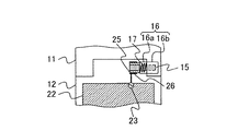
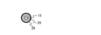
図8は、実施例1の第3の変形例の構成と電気的接続を図6と同じ向きに見て表す図である。図8において、図2ないし図5に表した各構成と同じ構成には同じ符号を付して表し、説明を省略する。図8に示すように、軸部材15のうち軸受け部材16の外側に露出した部分を取り囲む形で非導電性の外囲部材25が設けられる。外囲部材25のさらに外周には、導体パターン26が例えばめっきされて設けられる。図9は、上記のような軸部材15の露出部分の構成を、図8における紙面に垂直な断面において表す図である。
FIG. 8 is a diagram illustrating the configuration and electrical connection of the third modification example of the first embodiment when viewed in the same direction as FIG. 6. In FIG. 8, the same components as those illustrated in FIGS. 2 to 5 are denoted by the same reference numerals, and description thereof is omitted. As shown in FIG. 8, a
図8に示すように、導体パターン26がアンテナ給電回路23に接続されて、アンテナ素子として励振されることにより、携帯通信端末1用のアンテナ装置を構成する。このように構成されたアンテナ装置は、軸部材15及び軸受け部材16に対して非導電性の外囲部材25により隔てられているので、軸部材15及び軸受け部材16間の回動に伴う金属部の相対的な位置関係の変化に対するアイソレーションを向上させアンテナ特性を安定に保つことができる。
As shown in FIG. 8, the
図10は、実施例1の第4の変形例の構成と電気的接続を図6と同じ向きに見て表す図である。図10において、図2ないし図5に表した各構成と同じ構成には同じ符号を付して表し、説明を省略する。図10に示すように、軸部材15とアンテナ給電回路23の間に整合回路として並列共振回路27を設けることができる。並列共振回路27の並列共振周波数を軸部材15の共振周波数と異ならせることにより、複共振化することができる。
FIG. 10 is a diagram illustrating the configuration and electrical connection of the fourth modification example of the first embodiment when viewed in the same direction as FIG. 6. 10, the same components as those illustrated in FIGS. 2 to 5 are denoted by the same reference numerals, and description thereof is omitted. As shown in FIG. 10, a
図11は、実施例1の第5の変形例の構成と電気的接続を図6と同じ向きに見て表す図である。図11において、図2ないし図5に表した各構成と同じ構成には同じ符号を付して表し、説明を省略する。第5の変形例においては、ヒンジ部13の第2筐体12側にアンテナ素子31が内蔵される。アンテナ素子31は、基板22に設けられたアンテナ給電回路32に接続されている。また、ヒンジ部13の第2筐体12側にアンテナ素子33が内蔵される。アンテナ素子33は、基板22に設けられたアンテナ給電回路34に接続されている。
FIG. 11 is a diagram illustrating the configuration and electrical connection of the fifth modification example of the first embodiment when viewed in the same direction as FIG. 6. 11, the same components as those illustrated in FIGS. 2 to 5 are denoted by the same reference numerals, and description thereof is omitted. In the fifth modified example, the
上記のような第5の変形例の構成によれば、軸部材15をアンテナ素子とするアンテナ装置とは別に、2つのアンテナ装置を備えることができる。これらのアンテナ装置は、いずれもヒンジ部13に内蔵されてスペース効率の向上に役立つと同時に、複数システムのアンテナとして多機能化に寄与するものである。
According to the configuration of the fifth modification as described above, two antenna devices can be provided separately from the antenna device having the
軸部材15からなるアンテナ素子とアンテナ素子31が図11に示すように互いに反対方向を向く逆L字型に形成され、かつ、アンテナ素子33に対して、軸部材15からなるアンテナ素子及びアンテナ素子31の素子先端を略直交配置することにより、同一方向を向く場合よりも素子間のアイソレーションを改善することができる。また、各アンテナ素子の間で給電されたとき分布する電圧値が高いところを離間させたり、対向する部分の面積が小さくなるような位置関係を選んだり、共振周波数又は3倍波周波数の近いアンテナ素子どうしを離間させたり、給電点近傍又は給電点から4分の1波長の奇数倍相当の箇所を離間させたりすることによっても、アイソレーションを改善することができる。
As shown in FIG. 11, the antenna element made of the
本発明の実施例1によれば、2筐体が相互に回動可能に連結されて構成された携帯通信端末のヒンジ部の軸部材をアンテナ素子として利用することにより、アンテナ特性が2筐体の回動による開閉の状態による影響を受けにくいようにすることができる。 According to the first embodiment of the present invention, by using the shaft member of the hinge portion of the mobile communication terminal configured such that the two casings are rotatably connected to each other, the antenna characteristics are two casings. It can be made difficult to be affected by the state of opening and closing due to the rotation of.
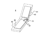
以下、図12ないし図14を参照して、本発明の実施例2を説明する。図12は、本発明の実施例2に係る無線装置である携帯通信端末4の構成を表す図である。携帯通信端末4は、第1筐体41と第2筐体42がヒンジ部43を介して開閉可能に接続されることにより構成されている。開閉の形式は、折りたたみ式、2軸ヒンジ(スウィーベル)式等が考えられるが、これらに限るものではない。
A second embodiment of the present invention will be described below with reference to FIGS. FIG. 12 is a diagram illustrating the configuration of the
上記のヒンジ部43は、第1筐体41と第2筐体42の間に位置して相互に開閉可能とする機構を内蔵する部分を指し、図12においては破線の楕円で囲んで表している。第1筐体41の正面側に表示部、第2筐体42の正面側に操作部がそれぞれ設けられる点は、実施例1について説明したのと同じである。
The
ヒンジ部43は実施例1のヒンジ部13と同様に構成され、軸部材15と軸受け部材16を収容している(図12においては図示を省略。)。軸部材15は第2筐体42に対して機械的に固定されており、第1筐体11に対して機械的に固定された軸受け部材16に挿通される。
The
図13は、携帯通信端末4の内部の構成を表す図である。図13においては、図12に表した第1筐体41、第2筐体42及びヒンジ部43の外形を破線で表し、内部の構成を実線で表している。第1筐体41は第1基板45を、第2筐体42は第2基板46をそれぞれ内蔵している。
FIG. 13 is a diagram illustrating an internal configuration of the
第2基板46には、シンボルで表したアンテナ給電回路47と、図示しない接地導体部が設けられている。金属材料で形成された軸部材15がアンテナ給電回路47に接続されてアンテナ素子として励振されることにより、携帯通信端末4用のアンテナ装置を構成する。
The
図13に示すように、第1基板41の右下の一部が下方に向かって延伸されている。第1基板41の上記の延伸された一部を含む範囲に、図示しない導体部が設けられている。当該第1基板41の導体部は、したがって、その端部が軸部材15に近接するように配設された形になる。軸部材15がアンテナ素子として励振されたとき、第1基板41の導体部は一種の無給電素子として軸部材15に電圧結合(又は電流結合)し、携帯通信端末4のアンテナ装置の実効的な体積を増大させて利得を高めることができる。
As shown in FIG. 13, a lower right part of the
図13に示した構成の変形例として、第1基板41の導体部がアンテナ素子の給電側に近接するレイアウトも考えられる。図14は、一例として携帯端末用の地上波デジタルテレビジョン放送(DTTV)の周波数範囲において、第1基板41の導体部とアンテナ素子の開放側若しくは給電側との近接の有無による放射効率の測定結果を例示する図である(なお実験では、軸部材15以外のヒンジ部43に配設されたアンテナ素子を用いた。)。
As a modification of the configuration shown in FIG. 13, a layout in which the conductor portion of the
図14の横軸は周波数(範囲は470−770メガヘルツ(MHz))、縦軸は放射効率(単位はデシベル(dB))である。図中の三角形のプロットは、上記のアンテナ素子の開放側と給電側の両方を、第1基板41の導体部に近接させた場合の実験結果である。円形のプロットは、開放側のみを第1基板41の導体部に近接させた場合の実験結果である。正方形のプロットは、給電側のみを第1基板41の導体部に近接させた場合の実験結果である。ひし形のプロットは、開放側も給電側も第1基板41の導体部に近接させない場合の実験結果である。
The horizontal axis of FIG. 14 is frequency (range is 470-770 megahertz (MHz)), and the vertical axis is radiation efficiency (unit is decibel (dB)). The triangular plots in the figure are experimental results when both the open side and the feed side of the antenna element are close to the conductor portion of the
図14の示すところによれば、周波数520MHz付近の低域側においては、アンテナ素子の開放側を第1基板41の導体部に近接させる方が放射効率の改善に寄与する。また、周波数670MHz付近の高域側においては、アンテナ素子の給電側を第1基板41の導体部に近接させる方が放射効率の改善に寄与する。
As shown in FIG. 14, on the low frequency side near the frequency of 520 MHz, bringing the open side of the antenna element closer to the conductor portion of the
したがって、携帯通信端末の例えばDTTV用アンテナ装置を低域側にチューニングさせたい場合に図13のように構成して、アンテナ装置をヒンジ部43の一方の側に寄せながら第1基板45の導体部に結合させることにより、チューニングの要求を満たすと同時にヒンジ部43の他方の側のスペースを空けて有効活用することができる。
Therefore, for example, when it is desired to tune a DTTV antenna device of a mobile communication terminal to the low frequency side, the conductor portion of the
なお、第1筐体41の少なくとも一部が導電性材料から形成された場合において、当該導電性材料から形成された一部が軸部材15に近接するように構成することによっても、実施例2と類似の効果を得ることができる。
In addition, when at least a part of the
本発明の実施例2によれば、アンテナ素子を携帯通信端末の筐体に内蔵された基板と結合させることにより、スペース利用効率とアンテナ特性の改善を図ることができるという、付加的な効果が得られる。 According to the second embodiment of the present invention, there is an additional effect that the space utilization efficiency and the antenna characteristics can be improved by combining the antenna element with the substrate built in the casing of the mobile communication terminal. can get.
以上の実施例の説明において、無線装置(携帯通信端末)、ヒンジ部及びアンテナ装置の構成、形状、接続、その他の部材の形状、配置等は例示であり、本発明の要旨を逸脱しない範囲でさまざまな変形が可能である。例えば、無線装置の筐体構成はいわゆる折りたたみ型に限定されるものではなく、2の筐体が相互に回動可能に連結されたいかなる構成にも本発明を適用することができる。 In the description of the above embodiments, the configurations, shapes, connections, shapes and arrangements of other members of the wireless device (mobile communication terminal), the hinge unit, and the antenna device are examples, and the scope of the present invention is not deviated. Various variations are possible. For example, the housing configuration of the wireless device is not limited to a so-called folding type, and the present invention can be applied to any configuration in which two housings are connected to each other so as to be rotatable.
1、4 携帯通信端末
11、41 第1筐体
12、42 第2筐体
13、43 ヒンジ部
15 軸部材
16 軸受け部材
16a カバー部
16b ヘッド部
17 スプリング
22、46 第2基板
23、32、34、47 アンテナ給電回路
25 外囲部材
26 導体パターン
27 並列共振回路
31、33 アンテナ素子
45 第1基板
1, 4
Claims (13)
前記第1の筐体に対して回動可能に連結され、アンテナ給電回路及び接地導体部を内蔵してなる第2の筐体と、
前記第2の筐体に固定されると共に導電性の部分を有してなる軸部材が、前記第1の筐体に固定されてなる軸受け部材に挿通されて前記第2の筐体の前記第1の筐体に対する回動の軸をなし、かつ、前記導電性の部分が前記アンテナ給電回路に接続されてなるヒンジ部とを
備えたことを特徴とする無線装置。 A first housing;
A second housing that is pivotally connected to the first housing and includes an antenna feeding circuit and a ground conductor;
A shaft member fixed to the second casing and having a conductive portion is inserted into a bearing member fixed to the first casing, and the second member of the second casing is 1. A radio apparatus comprising: a hinge portion that forms an axis of rotation with respect to one housing, and wherein the conductive portion is connected to the antenna feeding circuit.
前記基板は、前記導体部分の少なくとも一部が前記軸部材の前記アンテナ給電回路に接続された箇所から遠い側の端部に近接するように配設されたことを特徴とする請求項1に記載の無線装置。 A board that is built in the first housing and has a conductor portion, and is disposed so that at least a part of the conductor portion is close to the conductive portion of the shaft member;
The said board | substrate is arrange | positioned so that at least one part of the said conductor part may adjoin to the edge part of the side far from the location connected to the said antenna electric power feeding circuit of the said shaft member. Wireless devices.
前記基板は、前記導体部分の少なくとも一部が前記軸部材の前記アンテナ給電回路に接続された箇所に近接するように配設されたことを特徴とする請求項1に記載の無線装置。 A board that is built in the first housing and has a conductor portion, and is disposed so that at least a part of the conductor portion is close to the conductive portion of the shaft member;
The wireless device according to claim 1, wherein the substrate is disposed so that at least a part of the conductor portion is close to a portion of the shaft member connected to the antenna feeding circuit.
前記第2の筐体に固定されて導電性の部分を有する軸部材が前記第1の筐体に固定された軸受け部材に挿通され、かつ、前記軸部材の導電性の部分が前記第2の筐体に配設された基板の有するアンテナ給電回路に接続されてアンテナ素子を構成したことを特徴とするアンテナ装置。 In the antenna device for a wireless device configured such that the first housing and the second housing are connected to each other so as to be rotatable,
A shaft member fixed to the second casing and having a conductive portion is inserted through a bearing member fixed to the first casing, and the conductive portion of the shaft member is the second portion. An antenna device comprising an antenna element connected to an antenna feeding circuit of a substrate disposed in a housing.
Priority Applications (2)
| Application Number | Priority Date | Filing Date | Title |
|---|---|---|---|
| JP2008248960A JP5121649B2 (en) | 2008-09-26 | 2008-09-26 | Wireless device |
| US12/471,611 US8170635B2 (en) | 2008-09-26 | 2009-05-26 | Radio apparatus and antenna device for mobile radio system |
Applications Claiming Priority (1)
| Application Number | Priority Date | Filing Date | Title |
|---|---|---|---|
| JP2008248960A JP5121649B2 (en) | 2008-09-26 | 2008-09-26 | Wireless device |
Publications (2)
| Publication Number | Publication Date |
|---|---|
| JP2010081410A true JP2010081410A (en) | 2010-04-08 |
| JP5121649B2 JP5121649B2 (en) | 2013-01-16 |
Family
ID=42058038
Family Applications (1)
| Application Number | Title | Priority Date | Filing Date |
|---|---|---|---|
| JP2008248960A Active JP5121649B2 (en) | 2008-09-26 | 2008-09-26 | Wireless device |
Country Status (2)
| Country | Link |
|---|---|
| US (1) | US8170635B2 (en) |
| JP (1) | JP5121649B2 (en) |
Cited By (4)
| Publication number | Priority date | Publication date | Assignee | Title |
|---|---|---|---|---|
| WO2011145325A1 (en) * | 2010-05-17 | 2011-11-24 | パナソニック株式会社 | Handheld wireless device |
| JP2011239347A (en) * | 2010-05-13 | 2011-11-24 | Staf Corp | Hinge with built-in antenna |
| JP2012019283A (en) * | 2010-07-06 | 2012-01-26 | Panasonic Corp | Communication terminal |
| WO2014002378A1 (en) * | 2012-06-27 | 2014-01-03 | パナソニック株式会社 | Antenna device and portable radio equipment |
Families Citing this family (6)
| Publication number | Priority date | Publication date | Assignee | Title |
|---|---|---|---|---|
| JP5117367B2 (en) * | 2008-12-12 | 2013-01-16 | 株式会社東芝 | Portable terminal and housing integrated antenna |
| KR20100133536A (en) * | 2009-06-12 | 2010-12-22 | 삼성전자주식회사 | Built-in antenna for folder type portable terminal |
| KR101596043B1 (en) * | 2009-08-18 | 2016-02-22 | 삼성전자주식회사 | Swing type portable terminal |
| US9124680B2 (en) * | 2012-01-19 | 2015-09-01 | Google Technology Holdings LLC | Managed material fabric for composite housing |
| JP6139279B2 (en) | 2013-05-31 | 2017-05-31 | 株式会社東芝 | ANTENNA DEVICE AND ELECTRONIC DEVICE HAVING THE ANTENNA DEVICE |
| CN109244667B (en) * | 2018-08-29 | 2021-08-31 | Oppo广东移动通信有限公司 | Electronic device |
Citations (11)
| Publication number | Priority date | Publication date | Assignee | Title |
|---|---|---|---|---|
| JP2004229048A (en) * | 2003-01-24 | 2004-08-12 | Matsushita Electric Ind Co Ltd | Portable radio device |
| JP2004274729A (en) * | 2003-02-06 | 2004-09-30 | Matsushita Electric Ind Co Ltd | Portable radio communication apparatus |
| JP2004343165A (en) * | 2003-05-13 | 2004-12-02 | Sharp Corp | Antenna device and radio communication apparatus |
| JP2005006096A (en) * | 2003-06-12 | 2005-01-06 | Matsushita Electric Ind Co Ltd | Portable radio device |
| JP2006041899A (en) * | 2004-07-27 | 2006-02-09 | Sharp Corp | Antenna device, and portable radio set using it |
| JP2006042042A (en) * | 2004-07-28 | 2006-02-09 | Matsushita Electric Ind Co Ltd | Portable radio terminal |
| JP2006166225A (en) * | 2004-12-09 | 2006-06-22 | Matsushita Electric Ind Co Ltd | Foldable portable radio equipment |
| JP2007088692A (en) * | 2005-09-21 | 2007-04-05 | Matsushita Electric Ind Co Ltd | Portable radio device |
| JP2007214740A (en) * | 2006-02-08 | 2007-08-23 | Fujitsu Ltd | Antenna mounting system to folding portable terminal mounting noncontact ic card |
| JP2007318236A (en) * | 2006-05-23 | 2007-12-06 | Matsushita Electric Ind Co Ltd | Portable radio device |
| JP2008118359A (en) * | 2006-11-02 | 2008-05-22 | Nec Corp | Walkie-talkie |
Family Cites Families (1)
| Publication number | Priority date | Publication date | Assignee | Title |
|---|---|---|---|---|
| CN1957504B (en) * | 2004-10-28 | 2012-02-22 | 松下电器产业株式会社 | Foldable portable radio |
-
2008
- 2008-09-26 JP JP2008248960A patent/JP5121649B2/en active Active
-
2009
- 2009-05-26 US US12/471,611 patent/US8170635B2/en active Active
Patent Citations (11)
| Publication number | Priority date | Publication date | Assignee | Title |
|---|---|---|---|---|
| JP2004229048A (en) * | 2003-01-24 | 2004-08-12 | Matsushita Electric Ind Co Ltd | Portable radio device |
| JP2004274729A (en) * | 2003-02-06 | 2004-09-30 | Matsushita Electric Ind Co Ltd | Portable radio communication apparatus |
| JP2004343165A (en) * | 2003-05-13 | 2004-12-02 | Sharp Corp | Antenna device and radio communication apparatus |
| JP2005006096A (en) * | 2003-06-12 | 2005-01-06 | Matsushita Electric Ind Co Ltd | Portable radio device |
| JP2006041899A (en) * | 2004-07-27 | 2006-02-09 | Sharp Corp | Antenna device, and portable radio set using it |
| JP2006042042A (en) * | 2004-07-28 | 2006-02-09 | Matsushita Electric Ind Co Ltd | Portable radio terminal |
| JP2006166225A (en) * | 2004-12-09 | 2006-06-22 | Matsushita Electric Ind Co Ltd | Foldable portable radio equipment |
| JP2007088692A (en) * | 2005-09-21 | 2007-04-05 | Matsushita Electric Ind Co Ltd | Portable radio device |
| JP2007214740A (en) * | 2006-02-08 | 2007-08-23 | Fujitsu Ltd | Antenna mounting system to folding portable terminal mounting noncontact ic card |
| JP2007318236A (en) * | 2006-05-23 | 2007-12-06 | Matsushita Electric Ind Co Ltd | Portable radio device |
| JP2008118359A (en) * | 2006-11-02 | 2008-05-22 | Nec Corp | Walkie-talkie |
Cited By (4)
| Publication number | Priority date | Publication date | Assignee | Title |
|---|---|---|---|---|
| JP2011239347A (en) * | 2010-05-13 | 2011-11-24 | Staf Corp | Hinge with built-in antenna |
| WO2011145325A1 (en) * | 2010-05-17 | 2011-11-24 | パナソニック株式会社 | Handheld wireless device |
| JP2012019283A (en) * | 2010-07-06 | 2012-01-26 | Panasonic Corp | Communication terminal |
| WO2014002378A1 (en) * | 2012-06-27 | 2014-01-03 | パナソニック株式会社 | Antenna device and portable radio equipment |
Also Published As
| Publication number | Publication date |
|---|---|
| JP5121649B2 (en) | 2013-01-16 |
| US20100081489A1 (en) | 2010-04-01 |
| US8170635B2 (en) | 2012-05-01 |
Similar Documents
| Publication | Publication Date | Title |
|---|---|---|
| JP5121649B2 (en) | Wireless device | |
| JP4948177B2 (en) | Foldable portable radio | |
| JP4850839B2 (en) | Portable radio | |
| JP4358084B2 (en) | Foldable portable radio | |
| JP5355897B2 (en) | Portable radio | |
| JP4691958B2 (en) | Portable wireless terminal | |
| JP2007081712A (en) | Walkie talkie and antenna assembly | |
| JP2005006096A (en) | Portable radio device | |
| JPWO2006057350A1 (en) | Folding portable wireless device | |
| JP2005340887A (en) | Folding-type portable radio device | |
| JPWO2006112160A1 (en) | Foldable portable radio | |
| JP2006067361A (en) | Portable radio | |
| JP4279334B1 (en) | Wireless device and antenna device | |
| JP5521580B2 (en) | Portable wireless terminal | |
| JP2006304072A (en) | Portable radio apparatus | |
| JP2010109756A (en) | Portable wireless equipment | |
| JP4189433B1 (en) | Portable radio | |
| JP4312072B2 (en) | Portable radio | |
| JP2012134770A (en) | Radio communication apparatus | |
| JP2010278609A (en) | Portable radio device | |
| JP2006067133A (en) | Folding type portable radio device | |
| JP2004364331A (en) | Portable wireless device | |
| JP2010109703A (en) | Mobile device | |
| JP2012015976A (en) | Portable radio | |
| JP2005303542A (en) | Radio communication apparatus |
Legal Events
| Date | Code | Title | Description |
|---|---|---|---|
| A621 | Written request for application examination |
Free format text: JAPANESE INTERMEDIATE CODE: A621 Effective date: 20101119 |
|
| RD03 | Notification of appointment of power of attorney |
Free format text: JAPANESE INTERMEDIATE CODE: A7423 Effective date: 20101119 |
|
| A977 | Report on retrieval |
Free format text: JAPANESE INTERMEDIATE CODE: A971007 Effective date: 20120517 |
|
| A131 | Notification of reasons for refusal |
Free format text: JAPANESE INTERMEDIATE CODE: A131 Effective date: 20120612 |
|
| A521 | Written amendment |
Free format text: JAPANESE INTERMEDIATE CODE: A523 Effective date: 20120813 |
|
| TRDD | Decision of grant or rejection written | ||
| A01 | Written decision to grant a patent or to grant a registration (utility model) |
Free format text: JAPANESE INTERMEDIATE CODE: A01 Effective date: 20120925 |
|
| A01 | Written decision to grant a patent or to grant a registration (utility model) |
Free format text: JAPANESE INTERMEDIATE CODE: A01 |
|
| A61 | First payment of annual fees (during grant procedure) |
Free format text: JAPANESE INTERMEDIATE CODE: A61 Effective date: 20121023 |
|
| FPAY | Renewal fee payment (event date is renewal date of database) |
Free format text: PAYMENT UNTIL: 20151102 Year of fee payment: 3 |
|
| R151 | Written notification of patent or utility model registration |
Ref document number: 5121649 Country of ref document: JP Free format text: JAPANESE INTERMEDIATE CODE: R151 |
|
| FPAY | Renewal fee payment (event date is renewal date of database) |
Free format text: PAYMENT UNTIL: 20151102 Year of fee payment: 3 |
|
| S111 | Request for change of ownership or part of ownership |
Free format text: JAPANESE INTERMEDIATE CODE: R313121 Free format text: JAPANESE INTERMEDIATE CODE: R313117 |
|
| R350 | Written notification of registration of transfer |
Free format text: JAPANESE INTERMEDIATE CODE: R350 |