JP2010078473A - Ultrasonic flaw detector and ultrasonic flaw detection method - Google Patents
Ultrasonic flaw detector and ultrasonic flaw detection method Download PDFInfo
- Publication number
- JP2010078473A JP2010078473A JP2008247475A JP2008247475A JP2010078473A JP 2010078473 A JP2010078473 A JP 2010078473A JP 2008247475 A JP2008247475 A JP 2008247475A JP 2008247475 A JP2008247475 A JP 2008247475A JP 2010078473 A JP2010078473 A JP 2010078473A
- Authority
- JP
- Japan
- Prior art keywords
- ultrasonic
- flaw detection
- defect
- ultrasonic flaw
- wave
- Prior art date
- Legal status (The legal status is an assumption and is not a legal conclusion. Google has not performed a legal analysis and makes no representation as to the accuracy of the status listed.)
- Granted
Links
Images


Landscapes
- Investigating Or Analyzing Materials By The Use Of Ultrasonic Waves (AREA)
Abstract
Description
本発明は超音波探傷装置及び超音波探傷方法に関する。 The present invention relates to an ultrasonic flaw detection apparatus and an ultrasonic flaw detection method.
超音波探傷(以下UTと記載する)とは、検査対象に超音波を入射させて欠陥からの反射波を検出する検査手法である(特許文献1等参照)。 Ultrasonic flaw detection (hereinafter referred to as UT) is an inspection method in which an ultrasonic wave is incident on an inspection target and a reflected wave from a defect is detected (see Patent Document 1).
従来の横波によるUTでは垂直偏波横波(以下SV波と記載する)が用いられる。SV波とは検査面と垂直な面内で振動する超音波モードである。このSV波の反射効率は入射角に依存し、反射の際に入射波の一部が縦波に変換されて減衰するため信号強度が低下する。この減衰率は入射角に依存するため、入射角度によって検出感度が大きく変動する問題がある。 In a conventional UT using a transverse wave, a vertically polarized transverse wave (hereinafter referred to as an SV wave) is used. The SV wave is an ultrasonic mode that vibrates in a plane perpendicular to the inspection surface. The reflection efficiency of the SV wave depends on the incident angle, and a part of the incident wave is converted into a longitudinal wave and attenuates at the time of reflection, so that the signal intensity is lowered. Since this attenuation factor depends on the incident angle, there is a problem that the detection sensitivity varies greatly depending on the incident angle.
それに対し、水平偏波横波(以下SH波と記載する)を用いた場合には減衰による信号強度の低下が抑制される。SH波とはSV波と偏波方向が90°ずれた超音波モードであり、反射時に縦波への変換が起こらず反射効率が良いため高感度探傷が可能である。 On the other hand, when a horizontally polarized transverse wave (hereinafter referred to as SH wave) is used, a decrease in signal strength due to attenuation is suppressed. The SH wave is an ultrasonic mode in which the polarization direction is shifted by 90 ° from that of the SV wave, and conversion to a longitudinal wave does not occur at the time of reflection, and high sensitivity flaw detection is possible because of high reflection efficiency.
本発明は上記に鑑みなされたもので、検査波のSH波成分を増加させてUTの感度を向上させることができる超音波探傷装置及び超音波探傷方法を提供することを目的とする。 The present invention has been made in view of the above, and an object of the present invention is to provide an ultrasonic flaw detection apparatus and an ultrasonic flaw detection method capable of improving the sensitivity of the UT by increasing the SH wave component of the inspection wave.
(1)上記目的を達成するために、本発明は、欠陥に対して水平偏波横波を発信する超音波素子を複数配置した超音波探傷センサを有する超音波探傷装置であって、想定される3次元曲面形状の欠陥の長径方向の長さ及び曲率をそれぞれW1,R1、前記欠陥の短径方向の長さ及び曲率をそれぞれW2,R2、前記超音波探傷センサの長径方向の長さ及び曲率をそれぞれW1’,R1’、前記超音波探傷センサの短径方向の長さ及び曲率をそれぞれW2’,R2’とした場合、前記超音波探傷センサの底面を、
R1’÷R1=W1’÷W1 ・・・(1)
R2’÷R2=W2’÷W2 ・・・(2)
の関係が成立するような曲面形状とし、検査対象と各超音波素子との間に超音波を伝播させるシューを設けたことを特徴とする。
(1) In order to achieve the above object, the present invention is an ultrasonic flaw detection apparatus having an ultrasonic flaw detection sensor in which a plurality of ultrasonic elements that transmit horizontally polarized transverse waves to defects are arranged. The length and curvature in the major axis direction of the defect of the three-dimensional curved surface shape are W1 and R1, respectively, the length and curvature in the minor axis direction of the defect are W2 and R2, respectively, and the length and curvature in the major axis direction of the ultrasonic flaw detection sensor. Are W1 ′ and R1 ′, and the length and curvature in the minor axis direction of the ultrasonic flaw detection sensor are respectively W2 ′ and R2 ′, the bottom surface of the ultrasonic flaw detection sensor is
R1 ′ ÷ R1 = W1 ′ ÷ W1 (1)
R2 ′ ÷ R2 = W2 ′ ÷ W2 (2)
And a shoe for propagating the ultrasonic wave between the inspection object and each ultrasonic element.
(2)上記目的を達成するために、本発明は、欠陥に対して水平偏波横波を発信する超音波素子を複数配置した超音波探傷センサを有する超音波探傷装置であって、欠陥発生位置として想定される箇所に対して複数の方向から超音波が入射するように前記複数の超音波素子を配置したことを特徴とする。 (2) In order to achieve the above object, the present invention provides an ultrasonic flaw detection apparatus having an ultrasonic flaw detection sensor in which a plurality of ultrasonic elements that transmit a horizontally polarized transverse wave to a defect are arranged, and the defect occurrence position. The plurality of ultrasonic elements are arranged such that ultrasonic waves are incident from a plurality of directions to a place assumed as follows.
(3)上記(2)において、好ましくは、超音波素子を同心円上に配置したことを特徴とする。 (3) In the above (2), preferably, the ultrasonic elements are arranged concentrically.
(4)上記目的を達成するために、本発明は、欠陥に対して水平偏波横波を発信する超音波素子を複数配置した超音波探傷センサを有する超音波探傷装置であって、探傷箇所に角度の異なる複数の欠陥の発生が想定される場合、各欠陥とそれぞれ直交する面上に前記超音波素子を配置したことを特徴とする。 (4) In order to achieve the above object, the present invention provides an ultrasonic flaw detection apparatus having an ultrasonic flaw detection sensor in which a plurality of ultrasonic elements that transmit a horizontally polarized transverse wave to a defect are arranged. When the occurrence of a plurality of defects having different angles is assumed, the ultrasonic element is arranged on a plane orthogonal to each defect.
(5)上記目的を達成するために、本発明は、欠陥に対して水平偏波横波を発信する超音波素子を複数配置した超音波探傷センサを有する超音波探傷装置であって、回転アクチュエータ及び少なくとも2軸の並進アクチュエータを有し前記超音波探傷センサの平面移動と回転を可能とする移動機構と、検査対象の形状情報を基に強度計算を実行し想定される欠陥の形状及び位置を算出し、算出した欠陥の法線と検査対象の表面とが交わる点を超音波発信点として導き出す演算部と、前記移動機構に指令して前記超音波発信点に超音波探傷センサを移動させ、さらに前記演算した欠陥の位置に向けて発信する超音波が水平偏波横波となるように前記超音波探傷センサを回転させ、前記超音波探傷センサに指令して水平偏波横波を発信させる指令部とを備えたことを特徴とする。 (5) In order to achieve the above object, the present invention provides an ultrasonic flaw detection apparatus having an ultrasonic flaw detection sensor in which a plurality of ultrasonic elements that transmit a horizontally polarized wave to a defect are arranged, and includes a rotary actuator and A moving mechanism that has at least two axes of translational actuators and that allows the ultrasonic flaw detection sensor to move and rotate in a plane, and calculates the shape and position of an assumed defect by executing strength calculation based on the shape information of the inspection object A calculation unit for deriving a point where the calculated normal of the defect and the surface to be inspected intersect as an ultrasonic transmission point, and instructing the moving mechanism to move the ultrasonic flaw detection sensor to the ultrasonic transmission point, A command to rotate the ultrasonic flaw detection sensor so that the ultrasonic wave transmitted toward the calculated defect position becomes a horizontal polarization transverse wave, and to instruct the ultrasonic flaw detection sensor to emit a horizontal polarization transverse wave. Characterized by comprising and.
(6)上記(1)−(5)のいずれかにおいて、好ましくは、欠陥に直交する面と前記超音波素子の超音波の進行軸とのなす角が25°以下であることを特徴とする。 (6) In any one of the above (1) to (5), preferably, an angle formed by a surface orthogonal to the defect and an ultrasonic traveling axis of the ultrasonic element is 25 ° or less. .
(7)上記(1)−(6)のいずれかにおいて、好ましくは、応力分布解析装置又は応力分布解析結果データベースの少なくとも一方を有することを特徴とする。 (7) In any one of the above (1) to (6), preferably, at least one of a stress distribution analysis device and a stress distribution analysis result database is provided.
(8)上記目的を達成するために、本発明は、欠陥に対して水平偏波横波を発信する超音波素子を複数配置した超音波探傷センサを用いた超音波探傷方法であって、想定される3次元曲面形状の欠陥の長径方向の長さ及び曲率をそれぞれW1,R1、前記欠陥の短径方向の長さ及び曲率をそれぞれW2,R2、前記超音波探傷センサの長径方向の長さ及び曲率をそれぞれW1’,R1’、前記超音波探傷センサの短径方向の長さ及び曲率をそれぞれW2’,R2’とした場合、前記超音波探傷センサの底面を、
R1’÷R1=W1’÷W1 ・・・(1)
R2’÷R2=W2’÷W2 ・・・(2)
の関係が成立するような曲面形状とし、検査対象と各超音波素子との間に超音波を伝播させるシューを設けることを特徴とする。
(8) In order to achieve the above object, the present invention is an ultrasonic flaw detection method using an ultrasonic flaw detection sensor in which a plurality of ultrasonic elements that transmit a horizontally polarized wave to a defect are arranged. The length and curvature of the three-dimensional curved surface defect in the major axis direction are W1 and R1, respectively, the minor axis length and curvature of the defect are W2 and R2, respectively, and the major axis length of the ultrasonic flaw detection sensor and When the curvature is W1 ′, R1 ′, the length in the minor axis direction of the ultrasonic flaw detection sensor and the curvature are W2 ′, R2 ′, respectively, the bottom surface of the ultrasonic flaw detection sensor is
R1 ′ ÷ R1 = W1 ′ ÷ W1 (1)
R2 ′ ÷ R2 = W2 ′ ÷ W2 (2)
And a shoe for propagating ultrasonic waves between the inspection object and each ultrasonic element.
(9)上記目的を達成するために、本発明は、欠陥に対して水平偏波横波を発信する超音波素子を複数配置した超音波探傷センサを有する超音波探傷方法であって、欠陥発生位置として想定される箇所に対して複数の方向から超音波が入射するように前記複数の超音波素子を配置することを特徴とする。 (9) In order to achieve the above object, the present invention provides an ultrasonic flaw detection method including an ultrasonic flaw detection sensor in which a plurality of ultrasonic elements that transmit horizontally polarized transverse waves to a defect are arranged, and the defect occurrence position. The plurality of ultrasonic elements are arranged so that ultrasonic waves are incident from a plurality of directions on a place assumed as follows.
(10)上記目的を達成するために、本発明は、欠陥に対して水平偏波横波を発信する超音波素子を複数配置した超音波探傷センサを有する超音波探傷方法であって、探傷箇所に角度の異なる複数の欠陥の発生が想定される場合、各欠陥とそれぞれ直交する面上に前記超音波素子を配置することを特徴とする。 (10) In order to achieve the above object, the present invention provides an ultrasonic flaw detection method having an ultrasonic flaw detection sensor in which a plurality of ultrasonic elements that transmit a horizontally polarized transverse wave to a defect are arranged. When the generation of a plurality of defects having different angles is assumed, the ultrasonic element is arranged on a plane orthogonal to each defect.
(11)上記目的を達成するために、本発明は、欠陥に対して水平偏波横波を発信する超音波素子を複数配置した超音波探傷センサを有する超音波探傷方法であって、検査対象の形状情報を基に強度計算を実行し想定される欠陥の形状及び位置を算出し、算出した欠陥の法線と検査対象の表面とが交わる点を超音波発信点として導き出し、前記超音波発信点に超音波探傷センサを移動させ、さらに前記演算した欠陥の位置に向けて発信する超音波が水平偏波横波となるように前記超音波探傷センサを回転させ、前記超音波探傷センサによって前記演算した欠陥の位置に水平偏波横波を発信させることを特徴とする。 (11) In order to achieve the above object, the present invention provides an ultrasonic flaw detection method having an ultrasonic flaw detection sensor in which a plurality of ultrasonic elements that transmit horizontally polarized transverse waves to defects are arranged, Based on the shape information, intensity calculation is performed to calculate the shape and position of the assumed defect, and the point where the calculated normal of the defect intersects the surface to be inspected is derived as an ultrasonic transmission point, and the ultrasonic transmission point The ultrasonic flaw detection sensor is moved to the position of the calculated defect, and the ultrasonic flaw detection sensor is rotated so that the ultrasonic wave transmitted toward the calculated defect position becomes a horizontally polarized wave, and the calculation by the ultrasonic flaw detection sensor is performed. A horizontal polarized transverse wave is transmitted to the position of the defect.
(12)上記(8)−(11)のいずれかにおいて、好ましくは、欠陥に直交する面と前記超音波素子の超音波の進行軸とのなす角を25°以下とすることを特徴とする。 (12) In any one of the above (8) to (11), preferably, an angle formed by a surface orthogonal to the defect and an ultrasonic traveling axis of the ultrasonic element is 25 ° or less. .
(13)上記(8)−(12)のいずれかにおいて、好ましくは、検査対象の形状を基に検査対象の応力分布を解析し、その解析によって特定した応力分布の高い箇所を超音波探傷することを特徴とする。 (13) In any one of the above (8) to (12), preferably, the stress distribution of the inspection object is analyzed based on the shape of the inspection object, and an ultrasonic flaw detection is performed on a portion having a high stress distribution specified by the analysis. It is characterized by that.
(14)上記(8)−(12)のいずれかにおいて、好ましくは、応力分布解析結果に基づき作成されたデータベース上の応力分布の高い箇所を超音波探傷することを特徴とする。 (14) In any one of the above (8) to (12), preferably, ultrasonic flaw detection is performed on a portion having a high stress distribution on a database created based on a stress distribution analysis result.
(15)上記(8)−(12)のいずれかにおいて、好ましくは、欠陥発生事例データベースに基づき欠陥発生頻度の高い箇所を超音波探傷することを特徴とする。 (15) In any one of the above (8) to (12), preferably, an ultrasonic flaw detection is performed on a location with a high defect occurrence frequency based on a defect occurrence case database.
本発明によれば、検査波のSH波成分を増加させてUTの感度を向上させることができる。 According to the present invention, the sensitivity of the UT can be improved by increasing the SH wave component of the inspection wave.
以下に図面を用いて本発明の実施の形態を説明する。 Embodiments of the present invention will be described below with reference to the drawings.
まず、ここでは超音波探傷の背景技術についてその課題とともに説明する。 First, the background art of ultrasonic flaw detection will be described along with its problems.
<第1の実施の形態>
ここでは、まず本実施の形態の技術的背景について説明する。
<First Embodiment>
Here, first, the technical background of the present embodiment will be described.
超音波探傷(以下UTと記載する)とは、検査対象に超音波を入射させて欠陥からの反射波を検出する検査手法である。図1(a)に示すように検査対象2に欠陥が無い場合にはUTセンサ1に反射波は戻ってこないが、図1(b)に示すように検査対象2に欠陥3がある場合には欠陥3からの反射波がUTセンサ1に戻ってくる。この反射波を検出することで欠陥3の存在を検出する。
Ultrasonic flaw detection (hereinafter referred to as UT) is an inspection method in which an ultrasonic wave is incident on an inspection object and a reflected wave from a defect is detected. When the
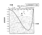
従来の横波によるUTは垂直偏波横波(以下、SV波と記載する)を用いている。SV波とは、図2(a)に示したように検査対象2の検査面(反射面)と垂直な面内で振動する(進行軸と偏波面を含む面が検査面に直交する)超音波モードである。このSV波の反射効率は図3に示す入射角依存性を持つ。SV波は反射の際に入射波の一部が縦波へ変換されて減衰し信号強度が低下するため、検出感度の低下の問題を伴う。 A conventional UT using a transverse wave uses a vertically polarized transverse wave (hereinafter referred to as an SV wave). As shown in FIG. 2A, the SV wave is a super-vibration in a plane perpendicular to the inspection surface (reflection surface) of the inspection object 2 (a surface including the traveling axis and the polarization plane is orthogonal to the inspection surface). Sound wave mode. The SV wave reflection efficiency has the incident angle dependency shown in FIG. When the SV wave is reflected, a part of the incident wave is converted to a longitudinal wave and attenuated to reduce the signal intensity. This causes a problem of a decrease in detection sensitivity.
一方、水平偏波横波(以下、SH波と記載する)は図2(b)に示したようにSV波と偏波方向が90°ずれた超音波モードである。このSH波は反射時に縦波へのモード変換が起こらないため図3に示したように反射効率が99%以上と高く、高感度探傷が可能である。 On the other hand, a horizontally polarized wave (hereinafter referred to as SH wave) is an ultrasonic mode in which the polarization direction is shifted by 90 ° from the SV wave as shown in FIG. Since this SH wave does not undergo mode conversion to a longitudinal wave when reflected, the reflection efficiency is as high as 99% or more as shown in FIG. 3, and high-sensitivity flaw detection is possible.
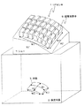
図4はSH波を紙面直交方向に傾斜させて反射面に入射させたときの概念図であり、入射波はSH波成分とSV波成分を有している。SH波成分とSV波成分は、反射面4と偏波方向(偏波面)とのなす角(偏波角)に対して図5に示すような依存性を持つため、SH波成分が支配的であっても偏波角が90°でなければSV波成分を持ち、偏波角が90°から離れるほどSV波成分が大きくなりSV波として反射される割合が増加して反射効率が低下する。SH波を用いるUTセンサもあるが、通常、図6に示すように複数の超音波素子5を格子状に配置して方形の保護ケース6で収容した構成であり、図7に示すような曲面形状の欠陥が探傷対象となる場合、全ての超音波素子5の超音波の偏波角を90°若しくはそれに近い角度とすることはできなかった。
FIG. 4 is a conceptual diagram when the SH wave is inclined in the direction orthogonal to the paper surface and incident on the reflecting surface. The incident wave has an SH wave component and an SV wave component. Since the SH wave component and the SV wave component have dependency as shown in FIG. 5 with respect to an angle (polarization angle) formed by the
以上を踏まえ、検査波のSH波成分を増加させてUTの感度を向上させることができる超音波探傷装置及び超音波探傷方法の実施の形態を説明する。 Based on the above, an embodiment of an ultrasonic flaw detection apparatus and an ultrasonic flaw detection method that can increase the sensitivity of the UT by increasing the SH wave component of the inspection wave will be described.
本実施の形態は、欠陥に対してSH波を発信する超音波素子を複数配置したUTセンサを有する超音波探傷装置であって、特に、想定される欠陥が3次元曲面形状である場合に有効な超音波探傷の例である。 The present embodiment is an ultrasonic flaw detection apparatus having a UT sensor in which a plurality of ultrasonic elements that transmit SH waves to defects is arranged, and is particularly effective when the assumed defect has a three-dimensional curved surface shape. This is an example of a simple ultrasonic flaw detection.
図8は本発明の第1の実施の形態に係る超音波探傷装置に用いるUTセンサの概略図である。 FIG. 8 is a schematic view of a UT sensor used in the ultrasonic flaw detector according to the first embodiment of the present invention.
図8に示したように、本実施の形態における超音波探傷装置は、3次元曲面形状の欠陥3の長径方向の長さをW1、曲率をR1、欠陥の短径方向の長さをW2、曲率をR2、UTセンサ1の長径方向の長さをW1’、曲率をR1’、UTセンサ1の短径方向の長さをW2’、曲率をR2’とした場合に、
R1’÷R1=W1’÷W1 ・・・(1)
R2’÷R2=W2’÷W2 ・・・(2)
の関係が成立するようにUTセンサ1の底面を曲面形状とし、検査対象2と超音波素子5間に超音波を伝播させるシュー7を設けている。すなわち、シュー7の上面(超音波素子5の搭載面)が上式(1)(2)の関係を満たす曲面形状をしており、底面が検査対象2の表面に当接する平面となっている。また、特に図示していないが、UTセンサ1は保護ケースで覆われている。
As shown in FIG. 8, the ultrasonic flaw detector according to the present embodiment has a three-dimensional
R1 ′ ÷ R1 = W1 ′ ÷ W1 (1)
R2 ′ ÷ R2 = W2 ′ ÷ W2 (2)
The bottom surface of the
図9は本実施の形態の超音波探傷の概略構成図、図10はその機能ブロック図である。 FIG. 9 is a schematic configuration diagram of ultrasonic flaw detection according to the present embodiment, and FIG. 10 is a functional block diagram thereof.
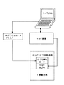
図9及び図10に示した超音波探傷装置は、パーソナルコンピュータ(パソコン)9、UT装置8、UTセンサ1より構成されている。
The ultrasonic flaw detection apparatus shown in FIGS. 9 and 10 includes a personal computer (personal computer) 9, a
パソコン9は、各種演算処理を実行するCPU21、演算結果や演算途中の値を一時的に記憶するRAM23、プログラムや必要な定数を記憶したROM24、HDD22、I/Oポート25、キーボード26、DVDやブルーレイディスクのような記録メディア27、モニタ28等を備えている。
The personal computer 9 includes a
UT装置8は、I/Oポート25、D/Aコンバータ30、A/Dコンバータ29を備えている。
The
図11はUTセンサ1の一構成例を表す概略構成図である。
図11に示したUTセンサ1は、検査対象に面する複数の圧電素子18と、各圧電素子18の底面(検査対象との対向面)及び上面に設けられた電極10,10と、電極10,10に電圧を印加する信号線15と、上側の電極10上に設けられ発信した超音波のエネルギーを吸収するダンパー11とを備えている。圧電素子18としてはPZT、LiNbO3、PVDF等の圧電素子を、電極10,10としてはAu,Ag,Cu等の導電性の高い金属を、信号線15としては銅線を、ダンパー11としてはHf,W,Ta等の金属を樹脂に混合したものをそれぞれ用いることができる。また、これらを覆う図示しない保護ケースは、樹脂、金属のうち1つ以上の材質からなるものを成型して用いることができる。また、ダンパー11は超音波発信時の残振を減らすので、これを設けることによってS/Nを向上させることができる。このような構成の超音波素子5を上式(1)及び(2)を満足するようにn行m列に2次元配置する。
FIG. 11 is a schematic configuration diagram illustrating a configuration example of the
The
図12は本実施の形態の超音波探傷装置を用いた超音波探傷方法の手順を表すフローチャートである。 FIG. 12 is a flowchart showing the procedure of an ultrasonic flaw detection method using the ultrasonic flaw detection apparatus of the present embodiment.
・ステップ101:検査情報の入力
予想される欠陥3の形状と位置、UTセンサ1の形状と位置、検査対象2の形状を図10に示したキーボード26、記録メディア27のうち1つ以上の入力装置から入力する。また、検査対象2の欠陥3の位置・大きさ・発生頻度に関するデータが蓄積されているときは、それらのデータを欠陥発生事例データベースとして、キーボード26、記録メディア27のうち1つ以上の入力装置から入力する。これらの情報はI/Oポート25を介してCPU21に伝達され、HDD22、RAM23、ROM24の少なくとも1つの記憶装置に記憶される。これらの形状等の情報はI/Oポート25を介してCPU21に伝達され、ハードディスクドライブ(HDD)22、ランダムアクセスメモリ(RAM)23、リードオンリーメモリ(ROM)24の少なくとも1つの記憶装置に記憶される。
Step 101: Input of inspection information Input one or more of the expected shape and position of the
・ステップ102:欠陥位置・形状解析
検査対象2の形状情報を基にCPU21で検査対象2の構造的な強度計算を実行し、その計算結果を基に欠陥3の形状及び位置を解析し予測しても良い。解析結果はHDD22、RAM23、ROM24のうちの少なくとも1つの記憶装置に記憶される。このように、CPU21は応力分布解析手段として機能し、解析によって特定した応力分布の高い箇所をUTの対象箇所とする。また、解析結果を記憶する記憶装置(先のHDD22、RAM23、ROM24のうちの少なくとも1つ)には、応力分布の解析結果がデータベースとして格納される。
Step 102: Defect position / shape analysis Based on the shape information of the
・ステップ103:超音波発信開始時間差計算
検査対象2の形状、欠陥3の形状と位置、UTセンサ1の形状と位置、ステップ102で解析した欠陥形状及び位置情報に基づき、CPU21によってUTセンサ1を構成する各超音波素子5間の超音波発信開始時間差を計算する。
Step 103: Calculation of ultrasonic transmission start time difference Based on the shape of the
ここで、図13は各超音波素子の超音波発信開始時間計算方法の説明図である。欠陥位置を超音波収束点とした場合のUTセンサ1内に2次元配置した超音波素子5のi行j列の超音波素子と収束点との距離Lijを求め、k行l列番目の超音波素子の超音波発信開始時間差dtklを次式(3)に従ってCPU21で計算し、HDD22、RAM23、ROM24のうち1つ以上の記憶装置に記憶させる。
Here, FIG. 13 is an explanatory diagram of an ultrasonic transmission start time calculation method for each ultrasonic element. The distance Lij between the ultrasonic element in the i-th row and j-th column of the ultrasonic element 5 arranged two-dimensionally in the
dtkl=(Max(Lij)−Lkl)÷V ・・・(3)
ここで、
Max(Lij):超音波収束点と超音波素子との距離の最大値
Lkl:超音波の収束点とi行j列番目の超音波素子間の距離
V:超音波音速
である。
dtkl = (Max (Lij) −Lkl) ÷ V (3)
here,
Max (Lij): Maximum value of the distance between the ultrasonic convergence point and the ultrasonic element
Lkl: distance between the ultrasonic convergence point and the i-th and j-th ultrasonic elements V: ultrasonic velocity.
上式(3)で算出した超音波発信開始時間差に応じて各超音波素子5の発信開始時間をずらすことによって、各超音波素子5から収束点に同時に超音波が到達し収束点の超音波強度が高められて信号強度が向上する。 By shifting the transmission start time of each ultrasonic element 5 according to the difference between the ultrasonic transmission start times calculated by the above equation (3), the ultrasonic waves simultaneously reach the convergence point from each ultrasonic element 5 and the ultrasonic wave at the convergence point. The strength is increased and the signal strength is improved.
・ステップ104:UTセンサ設置
検査対象2上にUTセンサ1を設置する。
Step 104: UT sensor installation The
・ステップ105:UT実行
超音波発信開始時間差に応じて、図10のパソコン9のI/O25ポート及びUT装置8のI/Oポート25、D/Aコンバータ30を介して、超音波素子5に電圧が印加され、超音波が発信される。
Step 105: UT execution Depending on the difference in ultrasonic transmission start time, the ultrasonic element 5 is passed through the I /
発信された超音波は検査対象2内に入射されて欠陥で反射される。欠陥からの反射波は超音波素子5で電圧として検出され、A/Dコンバータ29、UT装置8のI/Oポート25、パソコン9のI/Oポート25を介してCPU21に伝達され、HDD22、RAM23、ROM24のうち少なくとも1つの記憶装置に記憶される。また、I/Oポート25を介してモニタ28にUT結果を表示する。
The transmitted ultrasonic wave enters the
本実施の形態における超音波探傷システムは、以上説明したようにUTセンサ1の底面形状を欠陥3の形状と相似形とすることによって各超音波素子5の入射波の進行軸が欠陥3の曲面に直交するようになり、各超音波素子5から欠陥3に向けてSH波を発信した場合の入射波の偏波角が90°に近付くため、欠陥3からの反射波に占めるSH波成分が増加するのでUTの感度が向上する。
In the ultrasonic flaw detection system according to the present embodiment, as described above, the bottom surface shape of the
<第2の実施の形態>
本実施の形態は、欠陥に対してSH波を発信する超音波素子を複数配置したUTセンサを有する超音波探傷装置であって、特に、発生する欠陥の角度が定まらない場合に有効な例である。概略的には、欠陥発生位置として想定される箇所に対して複数の方向から超音波が入射するように複数の超音波素子を配置する例であり、本実施の形態における超音波探傷装置はUTセンサの超音波素子の配列が異なる点とシューが不要である点を除いて第1の実施の形態と同様とする。
<Second Embodiment>
The present embodiment is an ultrasonic flaw detection apparatus having a UT sensor in which a plurality of ultrasonic elements that transmit SH waves to defects are arranged, and is an example that is particularly effective when the angle of the generated defect cannot be determined. is there. Schematically, it is an example in which a plurality of ultrasonic elements are arranged so that ultrasonic waves are incident from a plurality of directions with respect to a place assumed as a defect occurrence position, and the ultrasonic flaw detection apparatus in the present embodiment is a UT. The configuration is the same as that of the first embodiment except that the arrangement of the ultrasonic elements of the sensor is different and a shoe is unnecessary.
第1の実施の形態では3次元曲面形状の欠陥3を想定した場合を例示したが、欠陥3が曲面形状でなくとも、図14に示すように平面的に格子状に超音波素子を格子配列した従来のUTセンサを検査対象に固定してUTを行う場合には、発生する欠陥の角度によって偏波角が変化するため、超音波素子から欠陥に入射する超音波の偏波角を90°若しくはそれに近い角度とすることができなかった。この場合もやはりSV波成分が増加して反射効率が低下する。
In the first embodiment, the case where the
そこで、本実施の形態では、図15に示すように、想定される欠陥発生位置に異なる角度で発生する複数の欠陥3を想定し、各欠陥3の交線方向から見た場合、各欠陥3の法線上の点を結んだ曲面形状ないし多角形形状の領域にn行m列の超音波素子5を配置し、これをUTセンサ1としている。したがって各行のm個の超音波素子5は対象とする欠陥3に直交する面上に配置されている。本例ではn行m列の超音波素子5を同心円状に2次元配置した場合を例示している。
Therefore, in the present embodiment, as shown in FIG. 15, when a plurality of
これにより、欠陥3の角度に応じていずれかの行の超音波素子5からの偏波角が90°又はそれに近い角度となるため、偏波角が90°又はそれに最も近い角度となる超音波素子5を反射波の強度を基に選択し、選択した超音波素子5の検出結果を用いてUTを行うことで、欠陥3からの反射波に占めるSH波成分が増加するのでUTの感度が向上する。
As a result, the polarization angle from the ultrasonic element 5 in any row becomes 90 ° or an angle close thereto depending on the angle of the
<第3の実施の形態>
本実施の形態は、欠陥に対してSH波を発信する超音波素子を複数配置したUTセンサを有する超音波探傷装置であって、特に、探傷箇所に角度の異なる複数の欠陥の発生が想定される場合に有効な例であり、概略的には想定される各欠陥とそれぞれ直交する面上に超音波素子を配置した例である。第2の実施の形態では角度が予想できない単一の欠陥に対して各行の超音波素子の超音波素子の進行軸を合わせ、想定される欠陥発生位置に異なる複数の方向から超音波を入射させたのに対し、本実施の形態では角度の異なる複数の欠陥が発生する可能性が高い箇所に対して、想定される複数の欠陥のそれぞれに対して各行の超音波素子が超音波を発信する点で相違する。本実施の形態における超音波探傷装置はUTセンサの超音波素子の配列が異なる点を除いて第1の実施の形態と同様とする。
<Third Embodiment>
The present embodiment is an ultrasonic flaw detection apparatus having a UT sensor in which a plurality of ultrasonic elements that transmit SH waves to defects are arranged. In particular, it is assumed that a plurality of defects having different angles are generated at a flaw detection location. This is an example effective in the case where the ultrasonic element is arranged on a plane orthogonal to each assumed defect. In the second embodiment, the traveling axes of the ultrasonic elements of the ultrasonic elements in each row are aligned with respect to a single defect whose angle cannot be predicted, and ultrasonic waves are incident on the assumed defect occurrence positions from a plurality of different directions. In contrast, in the present embodiment, the ultrasonic elements in each row transmit ultrasonic waves to each of a plurality of assumed defects with respect to a place where a plurality of defects having different angles are highly likely to occur. It is different in point. The ultrasonic flaw detection apparatus according to the present embodiment is the same as that of the first embodiment except that the arrangement of the ultrasonic elements of the UT sensor is different.
角度の異なる複数の欠陥が発生する探傷箇所の例としては、例えばタービン動翼の翼フォークのピン穴周りが挙げられる。タービン動翼の翼フォークの構造について図16を用いて説明する。 As an example of the flaw detection location where a plurality of defects having different angles occur, for example, around a pin hole of a blade fork of a turbine rotor blade. The structure of the blade fork of the turbine blade will be described with reference to FIG.
図16に示したタービンは、ディスク41と、タービン動翼42と、ピン43とを備えている。なお、図16では、ディスク41の一部のみを一部断面で示している。
The turbine shown in FIG. 16 includes a
ディスク41は、回転軸の外周側に取り付けられた円盤状の部材であり、外周部にロータの回転軸方向(以下、ロータ軸方向と記載する)に列設されたディスクフォーク46を有しており、ディスクフォーク46には複数のピン穴45が軸方向に貫通して設けられている。
The
タービン動翼42は、翼植込部47と、翼取り付け部48と、翼部(プロフィル部)49とを備えている。翼植込部47は、タービン動翼42をディスク41に取り付けた姿勢(翼取り付け姿勢)においてディスク41側に位置する部分であり、複数の翼フォーク50を有している。翼フォーク50には、複数のピン穴51が軸方向に貫通して設けられている。フォーク50は、タービン動翼42をディスク41に取り付けた姿勢においてロータ径方向の内側に突出した部材であり、軸方向に複数配列されている。これらフォーク50は、ディスク41の外周部に係合するようにディスクフォーク46の間隔に対応する間隔で列設されている。翼取り付け部48は、ロータ径方向に所定の厚みを有する部分であって翼植込部47のロータ形方向外側に翼植込部47と一体に形成されている。翼取り付け部48のロータ径方向外側の翼取り付け面53にはタービン動翼42の翼部49が取り付けられている。また、翼取り付け部48は軸方向の両端に張出部52を有している。張出部52は、タービン動翼42をディスク41に取り付けた姿勢において、翼植込部47の軸方向の両端面よりも軸方向に突出している。
The
ディスクフォーク46のピン穴45と翼フォーク50のピン穴51は、タービン動翼42をディスク41に取り付けた姿勢において互いの位置が対応しており、ピン穴45,51にピン43を軸方向に挿通することでタービン動翼42がディスク41に対して固定される。ピン穴45,51は、タービン動翼42がディスク41に取り付けられた姿勢において互いの中心と直径が一致するようになっている。また、タービンの回転に伴ってピン穴45,51にかかる応力を分散して耐久性を向上させるため、ピン穴45,51は翼フォーク一枚当たりに複数設けられている。
The
しかしながら、このようなフォーク型のタービンロータでは、翼フォーク50にピン穴51を複数設けても、タービンの回転に伴ってかかる応力によりピン穴45,51の周囲に亀裂(以下、欠陥と記載する)が生じることがある。したがって、タービン動翼42の信頼性を確認するためにも翼フォーク50の欠陥検査技術が重要である。
However, in such a fork type turbine rotor, even if a plurality of pin holes 51 are provided in the
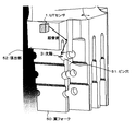
翼フォーク50のピン穴51の周囲の欠陥検出は図17に示すように張出し部52の軸方向を向いた面(以下、センサ設置面と記載する)にUTセンサ1を設置し、翼フォーク50の内面で超音波を反射させながら欠陥3の発生位置(発生の可能性が高い位置)に超音波を入射させ、欠陥3からの反射波を検出するものである。
As shown in FIG. 17, the defect detection around the
翼フォーク50のピン穴51の欠陥3は図18に示す範囲(ピン穴51の下半側(ディスク41側))に発生し易く、またピン穴51の半径方向に延びるように発生する傾向が知られている。この欠陥発生範囲をn分割してピン穴51の外周上の欠陥発生位置を想定し、各欠陥発生位置から垂線(ピン穴51の法線)を引いてこれらを欠陥3と想定する。そして、ピン穴51の軸方向から見て、ピン穴51の外周部近傍から張出部52側に延びる各欠陥3の法線を求め、これら法線を超音波の入射波の進行軸とする。センサ設置面上においてこれら法線に沿って超音波を発信可能な姿勢で各行の超音波素子5を配置し、これをもってUTセンサ1の形状とする。したがって、本例では各欠陥3に直交する面上に各行の超音波素子5が配置され、各超音波素子5が発信する超音波の進行軸は目標の欠陥3の直交面に沿う。また本例では、センサ設置面上の各法線上の点を結んで形成される多角の弧状又は円弧状の領域に、n行m列に超音波素子5を2次元配列してUTセンサ1を形成している。
The
欠陥3に直交する面上に超音波素子5が配置されるので、本実施の形態においても各超音波素子5から欠陥3に向けてSH波を発信した場合の入射波の偏波角を90°又はそれに近い角度とすることができる。そのため欠陥3からの反射波に占めるSH波成分が増加し、UTの感度が向上する。
Since the ultrasonic element 5 is arranged on the surface orthogonal to the
なお、図19に示すように超音波の入射ベクトルが法線からずれても許容範囲内であればUTに耐え得る反射効率を得ることはできる。例えばずれ角度が5°の場合にはずれ角度が0°の場合の50%の反射効率が得られる。ずれ角度が大きくなればそれだけ反射効率は落ちるが、ずれ角度が25°を超える領域ではずれ角度が0°の場合の5%程度の反射効率に収束する。言い換えれば、ずれ角度を25°以下の範囲ではずれ角度を小さくすることによって反射効率を向上させることができる。したがって、ずれ角度は少なくとも25°以内とし、0(ゼロ)又は0に近い角度が好ましい。このずれ角度の許容については他の実施の形態においても同様のことが言える。 As shown in FIG. 19, even if the incident vector of the ultrasonic wave deviates from the normal line, the reflection efficiency that can withstand the UT can be obtained as long as it is within an allowable range. For example, when the deviation angle is 5 °, a reflection efficiency of 50% as compared with the case where the deviation angle is 0 ° is obtained. As the deviation angle increases, the reflection efficiency decreases accordingly, but in a region where the deviation angle exceeds 25 °, the reflection efficiency converges to about 5% of the reflection angle when the deviation angle is 0 °. In other words, the reflection efficiency can be improved by reducing the shift angle in the range of 25 ° or less. Accordingly, the deviation angle is at least 25 °, and 0 (zero) or an angle close to 0 is preferable. The same can be said for the tolerance of this shift angle in other embodiments.
<第4の実施の形態>
本実施の形態は、欠陥に対してSH波を発信する超音波素子を複数配置したUTセンサを有する超音波探傷装置であって、特に、発生する欠陥の位置及び角度を特定し得る場合にUT感度の更なる向上を図る上で有効な例である。本実施の形態における超音波探傷装置はUTセンサの超音波素子の配列が異なる点を除いて第1の実施の形態と同様とする。
<Fourth embodiment>
The present embodiment is an ultrasonic flaw detection apparatus having a UT sensor in which a plurality of ultrasonic elements that transmit SH waves to defects is arranged, and in particular, when the position and angle of a generated defect can be specified. This is an effective example for further improving the sensitivity. The ultrasonic flaw detection apparatus according to the present embodiment is the same as that of the first embodiment except that the arrangement of the ultrasonic elements of the UT sensor is different.
図20は本実施の形態におけるUTセンサの構成図である。 FIG. 20 is a configuration diagram of the UT sensor in the present embodiment.
図20において、翼フォーク50の1つのピン穴51における発生確率が最も高い欠陥3から法線を張出部52のセンサ設置面上に引き、欠陥3と直交する方向に超音波素子5をn行m列に2次元配列(本例では格子配列)する。これらn×m個の超音波素子5が全て同一の欠陥3に向けて超音波を発信する場合、行毎に少しずつ偏波角が異なる。さらに、同じ翼フォーク50のピン穴51における発生確率が最も高い欠陥3から法線を張出部52のセンサ設置面上に引き、欠陥3と直交する方向に超音波素子5をn’行m’列に2次元配列(本例では格子配列)する。これらn’×m’個の超音波素子5が全て同一の欠陥3に向けて超音波を発信する場合も、行毎に少しずつ偏波角が異なる。本例ではn行m列とn’行m’列の2つの超音波素子群を合わせて1つのUTセンサ1としている。
In FIG. 20, a normal is drawn from the
なお、翼フォーク50のピン穴51では、下半側(ディスク側)の45°の位置が最も欠陥の発生確率が高く、また欠陥はピン穴51の径方向に延びる傾向がある。そのため、本例ではUTセンサ1が90°曲成されたL字型に形成されているが、欠陥の発生する確率が最も高い位置が異なる場合(45°位置でない場合)、或いは最も高確率に発生する欠陥を探傷するのではなく欠陥の有無を最優先で知りたい位置(45°位置ではない)を探傷する場合には、UTセンサ1の折れ角度は適宜異なってくる。
In the
本実施の形態によれば、発生する欠陥の位置及び角度を特定し得る場合にUT感度の更なる向上を図ることができる。加えて、本実施の形態におけるUTセンサ1は異なる複数のピン穴51のUTを同時に実行することができるため、UTの高速化の効果も得られる。
According to the present embodiment, it is possible to further improve the UT sensitivity when the position and angle of the generated defect can be specified. In addition, since the
<第5の実施の形態>
本実施の形態は、他の実施の形態と同じく欠陥に対してSH波を発信する超音波素子を複数配置したUTセンサを有する超音波探傷装置であって、特に、UTセンサを検査対象の表面に固定せず位置及び角度を調整することで欠陥にSH波を発信する例である。概略的には、回転アクチュエータ及び少なくとも2軸の並進アクチュエータを有しUTセンサの平面移動と回転を可能とする移動機構と、検査対象2の強度計算あるいは欠陥発生事例データベースに基づいて欠陥発生位置と形状を予測し、予測した欠陥の法線と検査対象の表面とが交わる点を超音波発信点として導き出す演算部と、上記移動機構に指令して上記超音波発信点にUTセンサを移動させ、さらに上記演算した欠陥の位置に向けて発信する超音波がSH波となるようにUTセンサを回転させ、UTセンサに指令してSH波を発信させる指令部とを備える。以下に具体的構成を簡単に説明する。
<Fifth embodiment>
The present embodiment is an ultrasonic flaw detection apparatus having a UT sensor in which a plurality of ultrasonic elements that transmit SH waves to defects are arranged as in the other embodiments, and in particular, the UT sensor is a surface to be inspected. This is an example in which an SH wave is transmitted to a defect by adjusting the position and angle without being fixed to. In general, a moving mechanism having a rotary actuator and a translational actuator of at least two axes and enabling the plane movement and rotation of the UT sensor, and a defect occurrence position based on intensity calculation of the
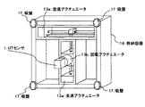
図21は本実施の形態の超音波探傷装置の概略構成図である。図21に示したように、本実施の形態の超音波探傷装置は、パソコン9、UT装置8、UTセンサ1、UTセンサ移動機構12、アクチュエータ13及びアクチュエータドライバ14を備えている。
FIG. 21 is a schematic configuration diagram of the ultrasonic flaw detector according to the present embodiment. As shown in FIG. 21, the ultrasonic flaw detector according to the present embodiment includes a personal computer 9, a
図22はUTセンサ1の構成図で、他の実施の形態と同様の超音波素子5を直線上に1次元配列したものであり、超音波素子5の配列を除いて他の実施の形態のUTセンサと同様である。
FIG. 22 is a configuration diagram of the
図23はUTセンサ移動機構12の構成図である。図23に示すように、UTセンサ移動機構12は、例えばモータやピエゾ素子等の駆動機構からなりUTセンサ1を平面移動させる少なくとも2軸の並進アクチュエータ13a、UTセンサ1を回転させる回転アクチュエータ13b、金属や樹脂等を成型して構成されたアクチュエータ収納用の格納容器16、及び格納容器16を検査対象2に固定する固定手段である吸盤17を備えている。このUTセンサ移動機構12によりUTセンサ1の位置及び角度を制御する。
FIG. 23 is a configuration diagram of the UT sensor moving mechanism 12. As shown in FIG. 23, the UT sensor moving mechanism 12 includes, for example, a driving mechanism such as a motor or a piezo element, and includes at least a biaxial translational actuator 13a that moves the
この超音波探傷システムを用いたUT手法を図24の機能ブロック図、及び図25の超音波探傷ステップの図を用いて説明する。 The UT method using this ultrasonic flaw detection system will be described with reference to the functional block diagram of FIG. 24 and the ultrasonic flaw detection step of FIG.
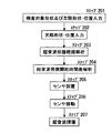
・ステップ201:検査対象形状及び欠陥形状・位置の入力
図24に示したキーボード26、記録メディア27のうち1つ以上の入力装置から予想される欠陥3の形状と位置、UTセンサ1の形状と位置、検査対象2の形状を入力する。また、検査対象2の欠陥発生事例に関するデータが蓄積されているときは、それらの事例を欠陥の位置・大きさ・発生頻度に関するデータベースとして、キーボード26、記録メディア27のうち1つ以上の入力装置から入力する。これらの形状情報はI/Oポート25を介してCPU21に伝達され、HDD22、RAM23、ROM24のうち1つ以上の記憶装置に記憶される。このように、CPU21は応力分布解析手段として機能し、解析によって特定した応力分布の高い箇所をUTの対象箇所とする。また、解析結果を記憶する記憶装置(先のHDD22、RAM23、ROM24のうちの少なくとも1つ)には、応力分布の解析結果がデータベースとして格納される。
Step 201: Input of Inspection Object Shape and Defect Shape / Position The shape and position of
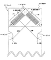
・ステップ202:欠陥位置の解析
欠陥3の形状及び位置は、検査対象の形状情報に基づきCPU21で検査対象2の強度計算を行い、解析・予測しても良い。
Step 202: Analysis of defect position The shape and position of the
・ステップ203:超音波伝播経路の解析
欠陥3位置から法線方向に超音波を発信させた場合の超音波伝播経路をCPU21で解析し、検査対象2表面への射出点を求め、その射出点をセンサ設置位置としてHDD22、RAM23、ROM24のうち1つ以上の記憶装置に記憶する。図26は超音波伝播経路の解析方法の説明図で、欠陥3から欠陥3の法線方向に直線を引き、検査対象2内の面に当たった際には鏡面に反射されると仮定してセンサ設置面への到達点を求める。この到達点から超音波を発信すると欠陥3に入射されるため、この点を超音波発信点とする。したがって、図24の機能ブロック図の場合、CPU21が前述した演算部に該当する。
Step 203: Analysis of Ultrasonic Propagation
・ステップ204:超音波発信開始時間差の解析
図27は各超音波素子の超音波発信開始時間計算方法の説明図である。図27において、UTセンサ1を構成する各超音波素子5と超音波収束点との距離Liを求め、k番目の超音波素子5の最初に発信開始する超音波素子との超音波発信開始時間差dtkをCPU21で次のように計算し、
dtk=(Max(Li)−Lk)÷V ・・・(4)
HDD22、RAM23、ROM24のうち1つ以上の記憶装置に記憶させる。
ここで、
Li:超音波収束点とi行目の超音波素子との距離
Lk:超音波収束点とk行目の超音波素子との距離
Max(Li):超音波収束点とi行目の超音波素子との距離の最大値
V:超音波音速
を表す。超音波発信開始時間差を上式(4)に従って求めることにより、各超音波素子5から収束点36に同時に超音波が到達し、収束点36の超音波強度が高められて信号強度が向上する。
Step 204: Analysis of difference in ultrasonic transmission start time FIG. 27 is an explanatory diagram of a method of calculating the ultrasonic transmission start time of each ultrasonic element. In FIG. 27, the distance Li between each ultrasonic element 5 constituting the
dtk = (Max (Li) −Lk) ÷ V (4)
The data is stored in one or more storage devices among the
here,
Li: Distance between the ultrasonic convergence point and the i-th ultrasonic element Lk: Distance between the ultrasonic convergence point and the k-th ultrasonic element Max (Li): Ultrasonic convergence point and the i-th ultrasonic wave Maximum value of distance from element V: Represents ultrasonic velocity. By obtaining the ultrasonic transmission start time difference according to the above equation (4), the ultrasonic waves simultaneously reach the
・ステップ205:センサの設置
UTセンサ1を固定したUTセンサ移動機構12を吸盤17で検査対象2上に固定する。また、UTセンサ1の初期設置位置をキーボード26から入力し、I/Oポート25を介してCPU21に伝達し、HDD22、RAM23、ROM24のうち1つ以上の記憶装置に記憶させる。
Step 205: Installation of Sensor The UT sensor moving mechanism 12 to which the
・ステップ206:センサの移動
ステップ203で求めた超音波発信点とステップ205で記録したUTセンサ1の位置に基づき、図24に示したCPU21からI/Oポート25を介してアクチュエータドライバ14にUTセンサ1の移動量の信号を送り、アクチュエータドライバ14からアクチュエータ13に電力を供給し、UTセンサ1を設置位置に移動させ、角度を調整する。したがって、図24の機能ブロック図の場合、CPU21が前述した指令部にも該当する。
Step 206: Sensor Movement Based on the ultrasonic transmission point obtained in step 203 and the position of the
・ステップ207:UTの実行
先に求めた超音波発信開始時間差を基に、図24に示したパソコン9のI/Oポート25及びUT装置8のI/Oポート25、D/Aコンバータ30を介して超音波素子5に電圧を印加し、超音波を発信する。
Step 207: Execution of UT Based on the ultrasonic transmission start time difference obtained previously, the I /
発信された超音波は欠陥3がある場合は欠陥3で反射される。反射された超音波は超音波素子5で電圧として検出され、A/Dコンバータ29、UT装置8のI/Oポート25、パソコン9のI/Oポート25を介してCPU21に伝達され、HDD22、RAM23、ROM24のうち1つ以上の記憶装置に記憶される。また、I/Oポート25を介してモニタ28にUT結果を表示する。
The transmitted ultrasonic wave is reflected by the
このように、本実施の形態においても高精度にSH波を欠陥に当てることができるので、前述した各実施の形態と同様の効果を得ることができる。また、予測した欠陥の位置や形状に応じてUTセンサ1の位置や角度を調整することができるので、UTセンサ1を固定する既述の各実施の形態と較べて超音波素子5の数を抑えることができる。これによってUT装置8を簡略化することができ、UT装置8を低廉化することができる。また、欠陥の位置や角度の解析結果に応じて柔軟にUTセンサ1の位置や姿勢を制御できるので、信頼性も向上する。
As described above, since the SH wave can be applied to the defect with high accuracy also in the present embodiment, the same effects as those of the above-described embodiments can be obtained. Further, since the position and angle of the
1 UTセンサ
2 検査対象
3 欠陥
4 反射面
5 超音波素子
6 保護ケース
7 シュー
8 UT装置
9 パソコン
10 電極
11 ダンパー
12 UTセンサ移動機構
13 アクチュエータ
13a 並進アクチュエータ
13b 回転アクチュエータ
14 アクチュエータドライバ
15 信号線
16 格納容器
17 固定機構
18 圧電素子
21 CPU
22 HDD
23 RAM
24 ROM
25 I/Oポート
27 記録メディア
28 モニタ
29 A/Dコンバータ
30 D/Aコンバータ
41 ディスク
42 タービン動翼
43 フォークピン
46 ディスクフォーク
45 ディスク側ピン穴
48 翼取り付け部
50 翼フォーク
51 ピン穴
52 張出部
53 翼取り付け面
DESCRIPTION OF
22 HDD
23 RAM
24 ROM
25 I /
Claims (15)
想定される3次元曲面形状の欠陥の長径方向の長さ及び曲率をそれぞれW1,R1、前記欠陥の短径方向の長さ及び曲率をそれぞれW2,R2、前記超音波探傷センサの長径方向の長さ及び曲率をそれぞれW1’,R1’、前記超音波探傷センサの短径方向の長さ及び曲率をそれぞれW2’,R2’とした場合、前記超音波探傷センサの底面を、
R1’÷R1=W1’÷W1 ・・・(1)
R2’÷R2=W2’÷W2 ・・・(2)
の関係が成立するような曲面形状とし、検査対象と各超音波素子との間に超音波を伝播させるシューを設けたことを特徴とする超音波探傷装置。 An ultrasonic flaw detection apparatus having an ultrasonic flaw detection sensor in which a plurality of ultrasonic elements that transmit horizontally polarized transverse waves to a defect are arranged,
The length and curvature of the assumed three-dimensional curved surface defect in the major axis direction are W1 and R1, respectively, the length and curvature of the defect in the minor axis direction are W2 and R2, respectively, and the length in the major axis direction of the ultrasonic flaw detection sensor. When the length and curvature are W1 ′ and R1 ′, and the length and curvature in the minor axis direction of the ultrasonic flaw detection sensor are W2 ′ and R2 ′, respectively, the bottom surface of the ultrasonic flaw detection sensor is
R1 ′ ÷ R1 = W1 ′ ÷ W1 (1)
R2 ′ ÷ R2 = W2 ′ ÷ W2 (2)
An ultrasonic flaw detector characterized by having a curved surface shape that satisfies the above relationship and providing a shoe for propagating ultrasonic waves between an inspection object and each ultrasonic element.
欠陥発生位置として想定される箇所に対して複数の方向から超音波が入射するように前記複数の超音波素子を配置したことを特徴とする超音波探傷装置。 An ultrasonic flaw detection apparatus having an ultrasonic flaw detection sensor in which a plurality of ultrasonic elements that transmit horizontally polarized transverse waves to a defect are arranged,
An ultrasonic flaw detector characterized in that the plurality of ultrasonic elements are arranged so that ultrasonic waves are incident from a plurality of directions on a position assumed as a defect occurrence position.
探傷箇所に角度の異なる複数の欠陥の発生が想定される場合、各欠陥とそれぞれ直交する面上に前記超音波素子を配置したことを特徴とする超音波探傷装置。 An ultrasonic flaw detection apparatus having an ultrasonic flaw detection sensor in which a plurality of ultrasonic elements that transmit horizontally polarized transverse waves to a defect are arranged,
An ultrasonic flaw detector in which the ultrasonic element is arranged on a surface orthogonal to each defect when the occurrence of a plurality of defects having different angles at the flaw detection location is assumed.
回転アクチュエータ及び少なくとも2軸の並進アクチュエータを有し前記超音波探傷センサの平面移動と回転を可能とする移動機構と、
検査対象の形状情報を基に強度計算を実行し想定される欠陥の形状及び位置を算出し、算出した欠陥の法線と検査対象の表面とが交わる点を超音波発信点として導き出す演算部と、
前記移動機構に指令して前記超音波発信点に超音波探傷センサを移動させ、さらに前記演算した欠陥の位置に向けて発信する超音波が水平偏波横波となるように前記超音波探傷センサを回転させ、前記超音波探傷センサに指令して水平偏波横波を発信させる指令部と
を備えたことを特徴とする超音波探傷装置。 An ultrasonic flaw detection apparatus having an ultrasonic flaw detection sensor in which a plurality of ultrasonic elements that transmit horizontally polarized transverse waves to a defect are arranged,
A moving mechanism having a rotary actuator and a translational actuator of at least two axes, and capable of moving and rotating the ultrasonic flaw detection sensor;
A calculation unit that calculates the shape and position of an assumed defect by executing an intensity calculation based on the shape information of the inspection target, and derives a point where the calculated normal of the defect intersects the surface of the inspection target as an ultrasonic transmission point; ,
The ultrasonic flaw detection sensor is moved so that the ultrasonic wave transmitted toward the calculated defect position becomes a horizontally polarized transverse wave by instructing the moving mechanism to move the ultrasonic flaw detection sensor to the ultrasonic wave transmission point. An ultrasonic flaw detection apparatus comprising: a command unit that rotates and commands the ultrasonic flaw detection sensor to transmit a horizontally polarized transverse wave.
想定される3次元曲面形状の欠陥の長径方向の長さ及び曲率をそれぞれW1,R1、前記欠陥の短径方向の長さ及び曲率をそれぞれW2,R2、前記超音波探傷センサの長径方向の長さ及び曲率をそれぞれW1’,R1’、前記超音波探傷センサの短径方向の長さ及び曲率をそれぞれW2’,R2’とした場合、前記超音波探傷センサの底面を、
R1’÷R1=W1’÷W1 ・・・(1)
R2’÷R2=W2’÷W2 ・・・(2)
の関係が成立するような曲面形状とし、検査対象と各超音波素子との間に超音波を伝播させるシューを設けることを特徴とする超音波探傷方法。 An ultrasonic flaw detection method using an ultrasonic flaw detection sensor in which a plurality of ultrasonic elements that transmit horizontally polarized transverse waves to a defect are arranged,
The length and curvature of the assumed three-dimensional curved surface defect in the major axis direction are W1 and R1, respectively, the length and curvature of the defect in the minor axis direction are W2 and R2, respectively, and the length in the major axis direction of the ultrasonic flaw detection sensor. When the length and curvature are W1 ′ and R1 ′, and the length and curvature in the minor axis direction of the ultrasonic flaw detection sensor are W2 ′ and R2 ′, respectively, the bottom surface of the ultrasonic flaw detection sensor is
R1 ′ ÷ R1 = W1 ′ ÷ W1 (1)
R2 ′ ÷ R2 = W2 ′ ÷ W2 (2)
An ultrasonic flaw detection method characterized by providing a curved surface shape that satisfies the above relationship and providing a shoe for propagating ultrasonic waves between an inspection object and each ultrasonic element.
欠陥発生位置として想定される箇所に対して複数の方向から超音波が入射するように前記複数の超音波素子を配置することを特徴とする超音波探傷方法。 An ultrasonic flaw detection method having an ultrasonic flaw detection sensor in which a plurality of ultrasonic elements that transmit horizontally polarized transverse waves to a defect are arranged,
An ultrasonic flaw detection method, wherein the plurality of ultrasonic elements are arranged so that ultrasonic waves are incident from a plurality of directions on a position assumed as a defect occurrence position.
探傷箇所に角度の異なる複数の欠陥の発生が想定される場合、各欠陥とそれぞれ直交する面上に前記超音波素子を配置することを特徴とする超音波探傷方法。 An ultrasonic flaw detection method having an ultrasonic flaw detection sensor in which a plurality of ultrasonic elements that transmit horizontally polarized transverse waves to a defect are arranged,
An ultrasonic flaw detection method characterized by arranging the ultrasonic element on a surface orthogonal to each defect when the occurrence of a plurality of defects having different angles at the flaw detection location is assumed.
検査対象の形状情報を基に強度計算を実行し想定される欠陥の形状及び位置を算出し、算出した欠陥の法線と検査対象の表面とが交わる点を超音波発信点として導き出し、
前記超音波発信点に超音波探傷センサを移動させ、さらに前記演算した欠陥の位置に向けて発信する超音波が水平偏波横波となるように前記超音波探傷センサを回転させ、前記超音波探傷センサによって前記演算した欠陥の位置に水平偏波横波を発信させる
ことを特徴とする超音波探傷方法。 An ultrasonic flaw detection method having an ultrasonic flaw detection sensor in which a plurality of ultrasonic elements that transmit horizontally polarized transverse waves to a defect are arranged,
Intensity calculation is performed based on the shape information of the inspection object, the shape and position of the assumed defect are calculated, and the point where the calculated normal of the defect intersects the surface of the inspection object is derived as an ultrasonic transmission point.
An ultrasonic flaw detection sensor is moved to the ultrasonic wave transmission point, and the ultrasonic flaw detection sensor is rotated so that the ultrasonic wave transmitted toward the calculated defect position becomes a horizontally polarized wave, and the ultrasonic flaw detection is performed. An ultrasonic flaw detection method, wherein a horizontally polarized wave is transmitted to a position of the calculated defect by a sensor.
Priority Applications (1)
| Application Number | Priority Date | Filing Date | Title |
|---|---|---|---|
| JP2008247475A JP5213611B2 (en) | 2008-09-26 | 2008-09-26 | Ultrasonic flaw detection apparatus and ultrasonic flaw detection method |
Applications Claiming Priority (1)
| Application Number | Priority Date | Filing Date | Title |
|---|---|---|---|
| JP2008247475A JP5213611B2 (en) | 2008-09-26 | 2008-09-26 | Ultrasonic flaw detection apparatus and ultrasonic flaw detection method |
Publications (2)
| Publication Number | Publication Date |
|---|---|
| JP2010078473A true JP2010078473A (en) | 2010-04-08 |
| JP5213611B2 JP5213611B2 (en) | 2013-06-19 |
Family
ID=42209094
Family Applications (1)
| Application Number | Title | Priority Date | Filing Date |
|---|---|---|---|
| JP2008247475A Expired - Fee Related JP5213611B2 (en) | 2008-09-26 | 2008-09-26 | Ultrasonic flaw detection apparatus and ultrasonic flaw detection method |
Country Status (1)
| Country | Link |
|---|---|
| JP (1) | JP5213611B2 (en) |
Cited By (2)
| Publication number | Priority date | Publication date | Assignee | Title |
|---|---|---|---|---|
| JP2013152227A (en) * | 2012-01-20 | 2013-08-08 | Boeing Co:The | Ultrasonic modeling for inspection of composite material irregularities |
| JP2013536946A (en) * | 2010-09-02 | 2013-09-26 | シーメンス エナジー インコーポレイテッド | Phased array ultrasonic inspection system for turbine and generator rotors |
Citations (9)
| Publication number | Priority date | Publication date | Assignee | Title |
|---|---|---|---|---|
| JPS5999253A (en) * | 1982-11-29 | 1984-06-07 | Mitsubishi Heavy Ind Ltd | Oblique probe for sh wave |
| JPH0419558A (en) * | 1990-05-15 | 1992-01-23 | Tokyo Gas Co Ltd | Image processing method for ultrasonic flaw detection test |
| JPH10332653A (en) * | 1997-06-05 | 1998-12-18 | Teitsuu Denshi Kenkyusho:Kk | Ultrasonic flaw detection method and device |
| JPH11337540A (en) * | 1998-05-25 | 1999-12-10 | Hitachi Eng Co Ltd | Electronic scanning type ultrasonic test equipment |
| JP2003130789A (en) * | 2001-10-29 | 2003-05-08 | Mitsubishi Heavy Ind Ltd | Method for evaluating life of metallic material |
| JP2004077292A (en) * | 2002-08-19 | 2004-03-11 | Osaka Gas Co Ltd | Method and device for inspecting stress corrosion cracking |
| JP2004251658A (en) * | 2003-02-18 | 2004-09-09 | Jfe Steel Kk | Ultrasonic angle probe |
| JP2006194591A (en) * | 2005-01-11 | 2006-07-27 | Mitsubishi Heavy Ind Ltd | Ultrasonic flaw detector |
| JP2006242770A (en) * | 2005-03-03 | 2006-09-14 | Japan Nuclear Cycle Development Inst States Of Projects | Electromagnetic ultrasonic flaw detection/measurement method and device |
-
2008
- 2008-09-26 JP JP2008247475A patent/JP5213611B2/en not_active Expired - Fee Related
Patent Citations (9)
| Publication number | Priority date | Publication date | Assignee | Title |
|---|---|---|---|---|
| JPS5999253A (en) * | 1982-11-29 | 1984-06-07 | Mitsubishi Heavy Ind Ltd | Oblique probe for sh wave |
| JPH0419558A (en) * | 1990-05-15 | 1992-01-23 | Tokyo Gas Co Ltd | Image processing method for ultrasonic flaw detection test |
| JPH10332653A (en) * | 1997-06-05 | 1998-12-18 | Teitsuu Denshi Kenkyusho:Kk | Ultrasonic flaw detection method and device |
| JPH11337540A (en) * | 1998-05-25 | 1999-12-10 | Hitachi Eng Co Ltd | Electronic scanning type ultrasonic test equipment |
| JP2003130789A (en) * | 2001-10-29 | 2003-05-08 | Mitsubishi Heavy Ind Ltd | Method for evaluating life of metallic material |
| JP2004077292A (en) * | 2002-08-19 | 2004-03-11 | Osaka Gas Co Ltd | Method and device for inspecting stress corrosion cracking |
| JP2004251658A (en) * | 2003-02-18 | 2004-09-09 | Jfe Steel Kk | Ultrasonic angle probe |
| JP2006194591A (en) * | 2005-01-11 | 2006-07-27 | Mitsubishi Heavy Ind Ltd | Ultrasonic flaw detector |
| JP2006242770A (en) * | 2005-03-03 | 2006-09-14 | Japan Nuclear Cycle Development Inst States Of Projects | Electromagnetic ultrasonic flaw detection/measurement method and device |
Cited By (2)
| Publication number | Priority date | Publication date | Assignee | Title |
|---|---|---|---|---|
| JP2013536946A (en) * | 2010-09-02 | 2013-09-26 | シーメンス エナジー インコーポレイテッド | Phased array ultrasonic inspection system for turbine and generator rotors |
| JP2013152227A (en) * | 2012-01-20 | 2013-08-08 | Boeing Co:The | Ultrasonic modeling for inspection of composite material irregularities |
Also Published As
| Publication number | Publication date |
|---|---|
| JP5213611B2 (en) | 2013-06-19 |
Similar Documents
| Publication | Publication Date | Title |
|---|---|---|
| JP4474395B2 (en) | Turbine fork ultrasonic flaw detector and method | |
| US9027404B2 (en) | Ultrasonic non-destructive evaluation methods for friction-welded blisks | |
| US9797867B2 (en) | Apparatus and method for inspecting a laminated structure | |
| EP2864768B1 (en) | Guided wave thermography methods and systems for inspecting a structure | |
| US10921291B2 (en) | Method for inspecting a weld seam | |
| JP2013536946A (en) | Phased array ultrasonic inspection system for turbine and generator rotors | |
| JP2005274557A (en) | Ultrasonic flaw detecting method and device | |
| JP5127573B2 (en) | Ultrasonic flaw detection apparatus and method | |
| JP4955359B2 (en) | Ultrasonic flaw detection apparatus and ultrasonic flaw detection method | |
| JP2011027571A (en) | Piping thickness reduction inspection apparatus and piping thickness reduction inspection method | |
| JP5213611B2 (en) | Ultrasonic flaw detection apparatus and ultrasonic flaw detection method | |
| JP7284181B2 (en) | Phased array ultrasonic transducer device for non-destructive inspection of objects to be inspected | |
| US9213019B2 (en) | Method of determining a size of a defect using an ultrasonic linear phased array | |
| JP5846847B2 (en) | 3D ultrasonic flaw detection method for turbine blade fork | |
| JP6298371B2 (en) | Ultrasonic flaw detection apparatus and ultrasonic flaw detection method | |
| JP4901925B2 (en) | Turbine fork ultrasonic flaw detector | |
| JP2009002832A (en) | Ultrasonic flaw inspection device and ultrasonic flaw inspection method | |
| JP5402894B2 (en) | Ultrasonic probe of ultrasonic flaw detector | |
| JP7180494B2 (en) | Ultrasonic flaw detector and ultrasonic flaw detection method | |
| JP6095916B2 (en) | Ultrasonic flaw detection method and apparatus | |
| JP2017167107A (en) | Ultrasonic wave probe sensor and ultrasonic wave probe method | |
| JP5738034B2 (en) | Ultrasonic flaw detector | |
| KR101206613B1 (en) | Double rotation waveguide ultrasonic sensor device | |
| WO2023032597A1 (en) | Ultrasonic inspection method, ultrasonic inspection device, and program | |
| Upendran et al. | The influence of edge waves in local surface skimming longitudinal wave generation using a focused PVDF transducer |
Legal Events
| Date | Code | Title | Description |
|---|---|---|---|
| A621 | Written request for application examination |
Free format text: JAPANESE INTERMEDIATE CODE: A621 Effective date: 20100506 |
|
| A977 | Report on retrieval |
Free format text: JAPANESE INTERMEDIATE CODE: A971007 Effective date: 20120323 |
|
| A131 | Notification of reasons for refusal |
Free format text: JAPANESE INTERMEDIATE CODE: A131 Effective date: 20121002 |
|
| A521 | Request for written amendment filed |
Free format text: JAPANESE INTERMEDIATE CODE: A523 Effective date: 20121203 |
|
| A131 | Notification of reasons for refusal |
Free format text: JAPANESE INTERMEDIATE CODE: A131 Effective date: 20121225 |
|
| A521 | Request for written amendment filed |
Free format text: JAPANESE INTERMEDIATE CODE: A523 Effective date: 20130130 |
|
| TRDD | Decision of grant or rejection written | ||
| A01 | Written decision to grant a patent or to grant a registration (utility model) |
Free format text: JAPANESE INTERMEDIATE CODE: A01 Effective date: 20130219 |
|
| A61 | First payment of annual fees (during grant procedure) |
Free format text: JAPANESE INTERMEDIATE CODE: A61 Effective date: 20130226 |
|
| R150 | Certificate of patent or registration of utility model |
Ref document number: 5213611 Country of ref document: JP Free format text: JAPANESE INTERMEDIATE CODE: R150 Free format text: JAPANESE INTERMEDIATE CODE: R150 |
|
| FPAY | Renewal fee payment (event date is renewal date of database) |
Free format text: PAYMENT UNTIL: 20160308 Year of fee payment: 3 |
|
| S111 | Request for change of ownership or part of ownership |
Free format text: JAPANESE INTERMEDIATE CODE: R313111 |
|
| R350 | Written notification of registration of transfer |
Free format text: JAPANESE INTERMEDIATE CODE: R350 |
|
| R250 | Receipt of annual fees |
Free format text: JAPANESE INTERMEDIATE CODE: R250 |
|
| R250 | Receipt of annual fees |
Free format text: JAPANESE INTERMEDIATE CODE: R250 |
|
| R250 | Receipt of annual fees |
Free format text: JAPANESE INTERMEDIATE CODE: R250 |
|
| R250 | Receipt of annual fees |
Free format text: JAPANESE INTERMEDIATE CODE: R250 |
|
| R250 | Receipt of annual fees |
Free format text: JAPANESE INTERMEDIATE CODE: R250 |
|
| S533 | Written request for registration of change of name |
Free format text: JAPANESE INTERMEDIATE CODE: R313533 |
|
| R350 | Written notification of registration of transfer |
Free format text: JAPANESE INTERMEDIATE CODE: R350 |
|
| R250 | Receipt of annual fees |
Free format text: JAPANESE INTERMEDIATE CODE: R250 |
|
| LAPS | Cancellation because of no payment of annual fees |