JP2010077977A - Suction cup device - Google Patents

Suction cup device Download PDF

Info

Publication number
JP2010077977A
JP2010077977A JP2008243443A JP2008243443A JP2010077977A JP 2010077977 A JP2010077977 A JP 2010077977A JP 2008243443 A JP2008243443 A JP 2008243443A JP 2008243443 A JP2008243443 A JP 2008243443A JP 2010077977 A JP2010077977 A JP 2010077977A
Authority
JP
Japan
Prior art keywords
polymer gel
suction cup
gel sheet
suction
gel layer
Prior art date
Legal status (The legal status is an assumption and is not a legal conclusion. Google has not performed a legal analysis and makes no representation as to the accuracy of the status listed.)
Granted
Application number
JP2008243443A
Other languages
Japanese (ja)
Other versions
JP4897973B2 (en
Inventor
Toru Yamana
徹 山名
Joji Morota
讓治 諸田
Current Assignee (The listed assignees may be inaccurate. Google has not performed a legal analysis and makes no representation or warranty as to the accuracy of the list.)
Murakami Corp
Original Assignee
Murakami Corp
Priority date (The priority date is an assumption and is not a legal conclusion. Google has not performed a legal analysis and makes no representation as to the accuracy of the date listed.)
Filing date
Publication date
Application filed by Murakami Corp filed Critical Murakami Corp
Priority to JP2008243443A priority Critical patent/JP4897973B2/en
Publication of JP2010077977A publication Critical patent/JP2010077977A/en
Application granted granted Critical
Publication of JP4897973B2 publication Critical patent/JP4897973B2/en
Expired - Fee Related legal-status Critical Current
Anticipated expiration legal-status Critical

Links

Images

Abstract

<P>PROBLEM TO BE SOLVED: To prevent air from being shut in between the suction surface of a suction cup and a high polymer gel sheet, even if a person unskilled at the sticking work of the high polymer gel sheet performs the sticking work, while replacing the high polymer gel sheet, in a suction cup device for arranging the high polymer gel sheet on the suction surface of the suction cup. <P>SOLUTION: The high polymer gel sheet 33 is detachably stuck to the suction surface 32 of the suction cup 30. An air bleeding hole 33a is formed in a plurality of positions different in the peripheral direction and in a plurality of positions different in the radial direction in the high polymer gel sheet 33. An air bleeding hole 33aa can also be formed at the center of the high polymer gel sheet 33. A positional dislocation preventive projection part 30a is formed in a plurality of positions different in the peripheral direction of the suction surface 32 of the suction cup 30, and a positional dislocation preventive hole 33b fitted with the positional dislocation preventive projection part 30a is formed in the high polymer gel sheet 33, and mutual positional dislocation of the suction cup 30 and the high polymer gel sheet 33 can also be prevented through the mutual fitting of the positional dislocation preventive projection part 30a and the positional dislocation preventive hole 33b. <P>COPYRIGHT: (C)2010,JPO&INPIT

Description

この発明は吸盤の吸着面に粘着性のある高分子ゲル層を配置した吸盤装置に関し、高分子ゲル層の交換を行うことができ、かつ高分子ゲル層の貼り付け作業に熟練していない者が貼り付け作業をしても吸盤の吸着面と高分子ゲル層との間に空気が閉じ込められにくくして高分子ゲル層による吸着力保持効果が十分に得られるようにしたものである。   The present invention relates to a suction cup device in which a sticky polymer gel layer is arranged on the suction surface of a suction cup, the person who can exchange the polymer gel layer and is not skilled in the pasting operation of the polymer gel layer However, even if affixing is performed, air is not easily trapped between the suction surface of the suction cup and the polymer gel layer, so that the effect of holding the adsorption force by the polymer gel layer can be sufficiently obtained.

吸着面に粘着性のある高分子ゲル層を配置した吸盤装置として下記特許文献1,2に記載されたものがあった。特許文献1記載の吸盤装置は吸盤の吸着面と該吸盤を吸着させる被吸着面との間に高分子ゲル層を該高分子ゲル層が持つ粘着性を利用して貼り付けたものである。特許文献2記載の吸盤装置は予め吸盤の吸着面に高分子ゲル層を二色成形や接着剤で接合したものである。   There exist some which were described in the following patent documents 1 and 2 as a suction cup apparatus which has arrange | positioned the adhesive polymer gel layer to the adsorption | suction surface. The suction cup device described in Patent Document 1 is obtained by pasting a polymer gel layer between the suction surface of the suction cup and the surface to be suctioned by which the suction cup is sucked using the adhesiveness of the polymer gel layer. The suction cup device described in Patent Document 2 is obtained by bonding a polymer gel layer to the suction surface of the suction cup in advance by two-color molding or an adhesive.

特開平11−257334号公報JP-A-11-257334 特開2007−285494号公報JP 2007-285494 A

特許文献1記載の吸盤装置によれば、吸盤の吸着面と高分子ゲル層との間に空気が閉じ込められやすいため吸盤の吸着面と高分子ゲル層との粘着が十分でなく、また該空気により吸盤の吸着効果が阻害される問題があった。したがって高分子ゲル層による吸着力保持効果が十分に得られない問題があった。特許文献2記載の吸盤装置によれば吸盤と高分子ゲル層とは製造時に気密に接合されるため高分子ゲル層による吸着力保持効果が十分に得られるが、高分子ゲル層が劣化しても該高分子ゲル層を交換できない問題があった。またたとえ高分子ゲル層を吸盤の吸着面に二色成形や接着剤で接合することなく高分子ゲル層自身の粘着性により吸盤の吸着面に着脱自在に貼り付けることにより高分子ゲル層を交換できるようにしても、高分子ゲル層は柔軟でしかも貼り付きやすいので高分子ゲル層の貼り付け作業に熟練していない者が貼り付け作業をすると吸盤の吸着面と高分子ゲル層との間に空気が閉じ込められやすく、高分子ゲル層による吸着力保持効果が十分に得られない問題があった。   According to the suction cup device described in Patent Document 1, since air is easily trapped between the suction surface of the suction cup and the polymer gel layer, adhesion between the suction surface of the suction cup and the polymer gel layer is not sufficient, and the air Therefore, there is a problem that the adsorption effect of the suction cup is hindered. Therefore, there is a problem that the effect of maintaining the adsorption force by the polymer gel layer cannot be obtained sufficiently. According to the suction cup device described in Patent Document 2, the suction cup and the polymer gel layer are hermetically joined at the time of manufacture, so that a sufficient retention effect of the polymer gel layer can be obtained. However, there was a problem that the polymer gel layer could not be exchanged. Even if the polymer gel layer is detachably attached to the suction surface of the suction cup by the adhesive property of the polymer gel layer without being bonded to the suction surface of the suction cup with two-color molding or an adhesive, the polymer gel layer is replaced. Even if it can be done, the polymer gel layer is flexible and easy to stick, so if a person who is not skilled in the polymer gel layer pasting work does the work between the suction surface of the suction cup and the polymer gel layer There is a problem that air is easily trapped and the effect of maintaining the adsorptive power by the polymer gel layer cannot be sufficiently obtained.

この発明は上述の点に鑑みてなされたもので、高分子ゲル層の交換を行うことができ、かつ高分子ゲル層の貼り付け作業に熟練していない者が貼り付け作業をしても吸盤の吸着面と高分子ゲル層との間に空気が閉じ込められにくくして高分子ゲル層による吸着力保持効果が十分に得られるようにした吸盤装置を提供しようとするものである。   The present invention has been made in view of the above points, and is capable of exchanging the polymer gel layer, and even if a person who is not skilled in the polymer gel layer pasting operation performs the pasting work, the suction cup It is intended to provide a suction cup device in which air is hardly confined between the adsorption surface and the polymer gel layer so that the effect of maintaining the adsorption force by the polymer gel layer can be sufficiently obtained.

この発明は吸盤の吸着面の周方向に異なる複数位置および径方向に異なる複数位置に対応する複数の位置にそれぞれ空気抜き穴を開設した高分子ゲル層を該吸着面に着脱自在に貼り付けてなるものである。これによれば高分子ゲル層を吸盤の吸着面に着脱自在に貼り付けたので、該高分子ゲル層が劣化した場合等には該高分子ゲル層を交換することができる。しかも該高分子ゲル層には吸着面の周方向に異なる複数位置および径方向に異なる複数位置に対応する複数の位置にそれぞれ空気抜き穴が開設されているので、貼り付け作業に熟練していない者が貼り付け作業をしても吸盤の吸着面と高分子ゲル層との間に空気が閉じ込められにくくなり、高分子ゲル層による吸着力保持効果を十分に得ることができる。   In the present invention, a polymer gel layer having air vent holes opened at a plurality of positions corresponding to a plurality of positions different in the circumferential direction of the suction surface of the suction cup and a plurality of positions different in the radial direction is detachably attached to the suction surface. Is. According to this, since the polymer gel layer is detachably attached to the suction surface of the suction cup, the polymer gel layer can be exchanged when the polymer gel layer is deteriorated. Moreover, the polymer gel layer has air vent holes at a plurality of positions corresponding to a plurality of positions different in the circumferential direction of the adsorption surface and a plurality of positions different in the radial direction. However, even if affixing work, air becomes difficult to be trapped between the suction surface of the suction cup and the polymer gel layer, and the effect of retaining the adsorption force by the polymer gel layer can be sufficiently obtained.

前記複数個の空気抜き穴は例えば同心円状に配列することができる。また放射状に配列することもできる。また高分子ゲル層の中央位置に空気抜き穴を配置することもできる。すなわち吸盤の吸着面の中央位置は高分子ゲル層との間に空気が閉じ込められやすいが、高分子ゲル層の中央位置に空気抜き穴を開設することにより該中央位置で吸盤の吸着面と高分子ゲル層との間に空気が閉じ込められなくなり、高分子ゲル層による吸着力保持効果を十分に得ることができる。   The plurality of air vent holes can be arranged concentrically, for example. They can also be arranged radially. Further, an air vent hole can be arranged at the center position of the polymer gel layer. That is, air is easily trapped between the suction surface of the suction cup and the polymer gel layer, but by opening an air vent hole at the center position of the polymer gel layer, the suction surface of the suction cup and the polymer are positioned at the center position. Air is not confined between the gel layer and the effect of retaining the adsorptive power by the polymer gel layer can be sufficiently obtained.

この発明に吸盤装置はさらに、吸盤の吸着面の周方向に異なる複数位置に位置ズレ防止凸部が形成され、前記高分子ゲル層に該位置ズレ防止凸部が嵌り込む位置ズレ防止穴または位置ズレ防止凹部が形成されたものとすることができる。これによれば吸盤の吸着面の位置ズレ防止凸部と高分子ゲル層の位置ズレ防止穴または位置ズレ防止凹部との嵌め合いにより、支持具を被吸着面に装着するときあるいは装着後の通常使用時等に高分子ゲル層が吸着面に対してずれるのが防止される。   The suction cup device according to the present invention further includes a position shift prevention convex part formed at a plurality of different positions in the circumferential direction of the suction surface of the suction cup, and the position shift prevention hole or position into which the position shift prevention convex part fits into the polymer gel layer. A misalignment prevention recess may be formed. According to this, when the support is attached to the surface to be sucked or after mounting, the protrusions on the suction surface of the suction cup are fitted with the position prevention holes or position prevention recesses of the polymer gel layer. The polymer gel layer is prevented from shifting with respect to the adsorption surface during use.

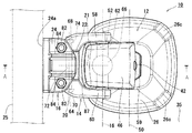
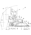
この発明の実施の形態を説明する。この実施の形態ではこの発明の吸盤装置を車載モニタ装置の支持具に適用した場合について説明する。はじめに図2を参照してこの実施の形態による支持具10の概要を説明する。支持具10はベース部12、回動部14、モニタ取付部16を具える。ベース部12は自動車の車室内でモニタ装置を設置しようとする箇所に、内蔵する吸盤30(図1)を用いて装着される。回動部14はベース部12に、回動軸18を中心に90°以上の角度範囲で回動自在に連結支持されている。回動軸18はベース部12の凹所28(図1)の開口端面が属する平面に対し平行に配置されている。モニタ取付部16は回動部14の先端部に、回動軸20を中心に90°以上の角度範囲で回動自在に連結支持された第二回動部22と、第二回動部22の中央部上面に形成されたピボット23(図1)に連結支持された据付部24を具える。回動軸20は回動軸18に対し平行に配置されている。据付部24の前面24aにはカーナビゲーションシステムの表示装置を構成する液晶ディスプレイ等によるモニタ装置25(図1、図3)がねじを用いて着脱自在に装着される。以上の構成によれば、ベース部12をダッシュボード上に吸盤30で装着した状態で、回動部14を回動軸18を中心に回動させることによりモニタ装置25の高さ位置が調整される。このとき回動部14はベース部12に対し、調整された回動角度に保持される。また第二回動部22を回動軸20を中心に回動させることによりモニタ装置25の上下方向の角度が調整される。このとき第二回動部22は回動部14に対し、調整された回動角度に保持される。また据付部24をピボット23を中心に傾動させることによりモニタ装置25の傾きが調整される。このとき据付部24は第二回動部22に対し、調整された傾動角度に保持される。   An embodiment of the present invention will be described. In this embodiment, a case where the suction cup device of the present invention is applied to a support for an in-vehicle monitor device will be described. First, an outline of the support 10 according to this embodiment will be described with reference to FIG. The support 10 includes a base portion 12, a rotation portion 14, and a monitor attachment portion 16. The base portion 12 is attached to a place where the monitor device is to be installed in the interior of the automobile using the built-in suction cup 30 (FIG. 1). The rotating part 14 is connected to and supported by the base part 12 so as to be rotatable in an angle range of 90 ° or more about the rotating shaft 18. The rotation shaft 18 is arranged in parallel to the plane to which the opening end surface of the recess 28 (FIG. 1) of the base portion 12 belongs. The monitor mounting portion 16 is connected to and supported by the distal end portion of the rotating portion 14 so as to be rotatable in an angle range of 90 ° or more around the rotating shaft 20, and the second rotating portion 22. An installation portion 24 connected to and supported by a pivot 23 (FIG. 1) formed on the upper surface of the central portion of the center portion is provided. The rotating shaft 20 is disposed in parallel to the rotating shaft 18. A monitor device 25 (FIGS. 1 and 3) such as a liquid crystal display constituting a display device of the car navigation system is detachably mounted on the front surface 24a of the installation unit 24 using screws. According to the above configuration, the height position of the monitor device 25 is adjusted by rotating the rotating unit 14 about the rotating shaft 18 in a state where the base 12 is mounted on the dashboard with the suction cup 30. The At this time, the rotation unit 14 is held at an adjusted rotation angle with respect to the base unit 12. Further, the angle of the monitor device 25 in the vertical direction is adjusted by rotating the second rotating portion 22 about the rotating shaft 20. At this time, the second rotation unit 22 is held at the adjusted rotation angle with respect to the rotation unit 14. Further, the inclination of the monitor device 25 is adjusted by tilting the installation portion 24 about the pivot 23. At this time, the installation part 24 is held at the adjusted tilt angle with respect to the second rotation part 22.

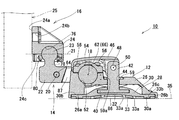
次に支持具10の各部の詳細構成を主に図1を参照して説明する。ベース部12は硬質合成樹脂、金属等で構成されたカバー26を具える。カバー26は下方に開口する凹所28を有する。凹所28には吸盤30が収容配置される。吸盤30の吸着面32は下方に向けられている。吸盤30の吸着面32の全面には粘着性のある高分子ゲル層として高分子ゲルシート33が高分子ゲルシート33自身の粘着性を利用して着脱自在に貼り付けられている。高分子ゲルシート33が貼り付けられた吸盤30は吸盤作用によりダッシュボード等の被吸着面35に吸着する。このとき高分子ゲルシート33は被吸着面35に粘着して吸盤30による吸着力を保持して該吸着状態を長期間にわたり維持する働きをする。   Next, the detailed configuration of each part of the support 10 will be described mainly with reference to FIG. The base portion 12 includes a cover 26 made of hard synthetic resin, metal or the like. The cover 26 has a recess 28 that opens downward. A suction cup 30 is accommodated in the recess 28. The suction surface 32 of the suction cup 30 is directed downward. A polymer gel sheet 33 is detachably attached to the entire suction surface 32 of the suction cup 30 as an adhesive polymer gel layer using the adhesive property of the polymer gel sheet 33 itself. The suction cup 30 to which the polymer gel sheet 33 is attached is adsorbed on a suction surface 35 such as a dashboard by a suction action. At this time, the polymer gel sheet 33 adheres to the surface to be adsorbed 35 and functions to maintain the adsorbing state for a long period of time by maintaining the adsorbing force by the suction cup 30.

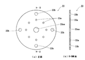
高分子ゲルシート33の面内の内周側寄りの位置には周方向に異なる複数位置および径方向に異なる複数位置に複数個の空気抜き穴33aが形成されている。この空気抜き穴33aの存在により、高分子ゲルシート33を吸盤30の吸着面32に貼り付けるときに、吸着面32と高分子ゲルシート33の間の空気をこの空気抜き穴33aを通して抜くことができ、これにより高分子ゲルシート33による十分な吸着力保持効果を得ることができる。また長年の使用等により高分子ゲルシート33が劣化して高分子ゲルシート33を新品に交換するときにも、吸着面32と新しい高分子ゲルシート33との間の空気をこの空気抜き穴33aを通して容易に抜くことができるので、交換後も高分子ゲルシート33による十分な吸着力保持効果を得ることができる。また高分子ゲルシート33の面内の外周側寄りの位置には周方向に均等の間隔で4個の位置ズレ防止穴33bが形成されている。この位置ズレ防止穴33bには吸盤30の吸着面32に形成された位置ズレ防止凸部30aが嵌め込まれる。これにより支持具10を被吸着面35に装着するときあるいは装着後の通常使用時等に高分子ゲルシート33が吸着面32に対してずれるのが防止される。   A plurality of air vent holes 33a are formed at a plurality of positions different in the circumferential direction and a plurality of positions different in the radial direction at positions closer to the inner peripheral side in the surface of the polymer gel sheet 33. Due to the presence of the air vent hole 33a, when the polymer gel sheet 33 is attached to the suction surface 32 of the suction cup 30, the air between the suction surface 32 and the polymer gel sheet 33 can be vented through the air vent hole 33a. A sufficient adsorbing force retention effect by the polymer gel sheet 33 can be obtained. Also, when the polymer gel sheet 33 is deteriorated due to long-term use or the like and the polymer gel sheet 33 is replaced with a new one, the air between the adsorption surface 32 and the new polymer gel sheet 33 is easily extracted through the air vent hole 33a. Therefore, a sufficient adsorbing force retention effect by the polymer gel sheet 33 can be obtained even after replacement. Further, at the position closer to the outer peripheral side in the surface of the polymer gel sheet 33, four misalignment prevention holes 33b are formed at equal intervals in the circumferential direction. The misalignment prevention convex portion 30a formed on the suction surface 32 of the suction cup 30 is fitted into the misalignment prevention hole 33b. This prevents the polymer gel sheet 33 from being displaced from the adsorption surface 32 when the support 10 is attached to the adsorption surface 35 or during normal use after attachment.

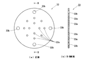
高分子ゲルシート33における空気抜き穴33aと位置ズレ防止穴33bの配置パターン例を図4に示す。高分子ゲルシート33は吸盤30と同等の外形を有する。この実施の形態の吸盤30は円形であり、高分子ゲルシート33は吸盤30と同一外径の円形に構成されている。空気抜き穴33aは2つの径方向位置に同心円状に配置されている。このうち内周側の空気抜き穴33aは周方向に均等間隔で4個配置されている。また外周側の空気抜き穴33aは周方向に均等間隔で8個配置されている。内周側の4個の空気抜き穴33aと外周側の8個の空気抜き穴33aの一部は同一周方向位置で放射状に配列されている。位置ズレ防止穴33bは空気抜き穴33aよりも外周側の1つの径方向位置に周方向に均等間隔で4個配置されている。   FIG. 4 shows an arrangement pattern example of the air vent holes 33a and the misalignment prevention holes 33b in the polymer gel sheet 33. As shown in FIG. The polymer gel sheet 33 has the same outer shape as the suction cup 30. The suction cup 30 of this embodiment is circular, and the polymer gel sheet 33 is configured in a circular shape with the same outer diameter as the suction cup 30. The air vent holes 33a are concentrically arranged at two radial positions. Among these, four air vent holes 33a on the inner peripheral side are arranged at equal intervals in the circumferential direction. Further, eight air vent holes 33a on the outer peripheral side are arranged at equal intervals in the circumferential direction. A part of the four air vent holes 33a on the inner peripheral side and the eight air vent holes 33a on the outer peripheral side are arranged radially at the same circumferential position. Four misalignment prevention holes 33b are arranged at equal intervals in the circumferential direction at one radial position on the outer peripheral side of the air vent hole 33a.

図1において、吸盤30の周縁部上面30bはその全周がカバー26の周縁部下面26aに当接支持される。カバー26の最外周部には吸盤30の外周縁部を包囲して隠す縁部26bが下方に向けて全周にわたり突出形成されている。カバー26の外周部にはベース部12を被吸着面35から外すときに指をかけるための隆起部26cが2箇所に形成されている。吸盤30の中央部には硬質合成樹脂、金属等で構成された円盤40が埋め込まれている。円盤40の中央部上面には円盤40と一体に、扁平な横断面形状を有する引き棒42が上方に突出して形成されている。引き棒42はカバー26の上面中央部に形成された穴44に通されてカバー26の上方に突出している。引き棒42はカバー26に対し上下方向に移動可能とされている。引き棒42の上部には蓋部46が軸棒48で回動自在に連結され、これにより蓋部46は軸棒48の中心を通る回動軸50を中心に回動自在とされている。回動軸50は回動軸18,20と平行に配置されている。蓋部46はカバー26上に露出する押さえ板54およびねじ56の頭部を隠す機能と、蓋部46の基端部に構成されているカム部57(図5、図6、図7)とカバー26の上面との当接により引き棒42をカバー26に対し引き上げる機能を有する。カバー26の上面には回動部14の基端部側軸棒62の下側半分を収容して支持する凹部52が形成されている。カバー26の上面には基端部側軸棒62の上側半分を収容する押さえ板54が4本のねじ56により固定されている。4本のねじ56はカバー26を貫通してカバー26の凹所28内でナット(図示せず)にねじ込まれて固定される。これにより基端部側軸棒62はその中心軸を通る回動軸18を中心に回動自在にベース部12に支持される。押さえ板54と4本のねじ56は、蓋部46を閉位置に回動させることにより外部から隠されて見えなくなる。   In FIG. 1, the entire periphery of the peripheral surface upper surface 30 b of the suction cup 30 is abutted and supported by the peripheral surface of the cover 26. On the outermost peripheral portion of the cover 26, an edge portion 26b surrounding and hiding the outer peripheral edge portion of the suction cup 30 is formed so as to protrude downward over the entire periphery. On the outer peripheral portion of the cover 26, two raised portions 26c for placing a finger when the base portion 12 is detached from the attracted surface 35 are formed. A disc 40 made of hard synthetic resin, metal or the like is embedded in the central portion of the suction cup 30. A pulling bar 42 having a flat cross-sectional shape is formed on the upper surface of the central portion of the disk 40 so as to be integral with the disk 40 and project upward. The pull bar 42 passes through a hole 44 formed in the center of the upper surface of the cover 26 and protrudes above the cover 26. The pull bar 42 is movable in the vertical direction with respect to the cover 26. A lid portion 46 is rotatably connected to the upper portion of the pull rod 42 by a shaft rod 48, so that the lid portion 46 is rotatable about a rotation shaft 50 passing through the center of the shaft rod 48. The rotation shaft 50 is arranged in parallel with the rotation shafts 18 and 20. The lid portion 46 has a function of hiding the heads of the holding plate 54 and the screw 56 exposed on the cover 26, and a cam portion 57 (FIGS. 5, 6, and 7) configured at the base end portion of the lid portion 46. It has a function of pulling up the pull bar 42 with respect to the cover 26 by contact with the upper surface of the cover 26. A concave portion 52 is formed on the upper surface of the cover 26 to accommodate and support the lower half of the base end side shaft rod 62 of the rotating portion 14. On the upper surface of the cover 26, a holding plate 54 that accommodates the upper half of the base end side shaft rod 62 is fixed by four screws 56. The four screws 56 pass through the cover 26 and are screwed into a nut (not shown) in the recess 28 of the cover 26 to be fixed. As a result, the base end side shaft rod 62 is supported by the base portion 12 so as to be rotatable about the rotation shaft 18 passing through the central axis thereof. The holding plate 54 and the four screws 56 are hidden from view by turning the lid portion 46 to the closed position and become invisible.

カバー26の上面中央部には金属板59が埋め込まれている。金属板59の中央部にはカバー26に形成された穴44に連通する穴59aが形成され、この穴59aには引き棒42が通されている。蓋部46の基端部に構成されているカム部57(図5、図6、図7)は、蓋部46を閉位置方向に回動させることにより金属板59の表面に当接して引き棒42を吸盤30の中央部を伴って引き上げる。   A metal plate 59 is embedded in the center of the upper surface of the cover 26. A hole 59a that communicates with a hole 44 formed in the cover 26 is formed at the center of the metal plate 59, and a pull bar 42 is passed through the hole 59a. The cam portion 57 (FIGS. 5, 6, and 7) formed at the base end portion of the lid portion 46 is brought into contact with the surface of the metal plate 59 by rotating the lid portion 46 in the closed position direction. The rod 42 is pulled up with the central part of the suction cup 30.

回動部14は図3に明確に示されているように、互いに間隙を隔てて配置された左右のアーム58,60と、アーム58,60の基端部間を相互に連結する基端部側軸棒62と、アーム58,60の自由端部間を相互に連結する自由端部側軸棒64を具え、全体として矩形の枠状に構成されている。この実施の形態ではアーム58,60と基端部側軸棒62は硬質合成樹脂で一体に構成されている。基端部側軸棒62の軸方向中央部には球状に膨出した大径部66が形成されている。大径部66は基端部側軸棒62の一部を大径にすることにより、基端部側軸棒62とカバー26および押さえ板54との間に生じる摩擦力を大きくする働きをするものである。この摩擦力により回動部14はモニタ装置25の荷重により下方に回動するのが防止される。基端部側軸棒62とカバー26および押さえ板54との間に生じる摩擦力は、押さえ板54をカバー26に装着する4本のねじ56を前記ナットにねじ込むねじ込み量により調整することができる。したがってこのねじ込み量によりこの摩擦力を適度な大きさに予め設定しておくことにより、運転者等はモニタ装置25に手で力を加えてベース部12に対する回動部14の回動位置(つまりモニタ装置25の高さ位置)を調整することができ、この調整した回動位置は保持される。   As clearly shown in FIG. 3, the rotating portion 14 includes left and right arms 58 and 60 that are arranged with a gap therebetween, and a base end portion that connects the base end portions of the arms 58 and 60 to each other. A side shaft rod 62 and a free end side shaft rod 64 that interconnects the free ends of the arms 58 and 60 are provided, and the whole is configured in a rectangular frame shape. In this embodiment, the arms 58 and 60 and the base end side shaft rod 62 are integrally formed of hard synthetic resin. A large-diameter portion 66 swelled in a spherical shape is formed at the axially central portion of the base end side shaft rod 62. The large diameter portion 66 functions to increase the frictional force generated between the base end portion side shaft rod 62 and the cover 26 and the pressing plate 54 by making a part of the base end portion side shaft rod 62 have a large diameter. Is. This frictional force prevents the rotating unit 14 from rotating downward due to the load of the monitor device 25. The frictional force generated between the base end side shaft rod 62 and the cover 26 and the pressing plate 54 can be adjusted by the amount of screwing into which the four screws 56 for mounting the pressing plate 54 to the cover 26 are screwed into the nut. . Therefore, by setting the frictional force to an appropriate magnitude in advance by the screwing amount, the driver or the like applies a force to the monitor device 25 by hand to turn the rotating portion 14 relative to the base portion 12 (that is, The height position of the monitor device 25 can be adjusted, and the adjusted rotation position is maintained.

回動部14の自由端部側軸棒64はこの実施の形態では、少なくとも先端部にねじ部が形成された金属製のねじ棒で構成されている。このねじ棒64はアーム60の自由端部側面に形成された穴70から第二回動部22に形成された穴72を経てアーム58の自由端部側面に形成された穴68に通される。ねじ棒64の先端部はアーム58の穴68から突出し、この突出したねじ部をナット74にねじ込むことによりねじ棒64はアーム58,60間に取り付けられる。このとき第二回動部22はアーム58,60間に挟み込まれた状態となる。この状態でナット74に対するねじ棒64のねじ込み量を加減することにより、アーム58,60が第二回動部22を挟み込む力が変化し、これによりアーム58,60と第二回動部22との当接面の摩擦力が変化する。したがってナット74に対するねじ棒64のねじ込み量によりこの摩擦力を適度な大きさに予め設定しておくことにより、運転者等はモニタ装置25に手で力を加えて回動部14に対する第二回動部22の回動位置を調整することができ、この調整した回動位置は保持される。   In this embodiment, the free end side shaft rod 64 of the rotating portion 14 is composed of a metal screw rod having a screw portion formed at least at the tip. The screw rod 64 passes from a hole 70 formed on the side surface of the free end of the arm 60 to a hole 68 formed on the side surface of the free end of the arm 58 through a hole 72 formed in the second rotating portion 22. . The tip of the screw rod 64 protrudes from the hole 68 of the arm 58, and the screw rod 64 is attached between the arms 58 and 60 by screwing the protruding screw portion into the nut 74. At this time, the second rotating portion 22 is sandwiched between the arms 58 and 60. In this state, by adjusting the screwing amount of the screw rod 64 with respect to the nut 74, the force with which the arms 58 and 60 pinch the second rotating portion 22 is changed, whereby the arms 58 and 60 and the second rotating portion 22 The frictional force of the abutting surface changes. Therefore, by setting the frictional force in advance to an appropriate magnitude according to the screwed amount of the screw rod 64 with respect to the nut 74, the driver or the like applies force to the monitor device 25 by hand to perform the second rotation on the rotating unit 14. The rotation position of the moving part 22 can be adjusted, and this adjusted rotation position is maintained.

モニタ取付部16の第二回動部22は硬質合成樹脂、金属等で構成される。第二回動部22の中央部上面には図1に明確に示されているように球状のピボット23が第二回動部22と一体に形成されている。ピボット23は据付部24の下面に形成された球形凹状のピボット受け76に上側半分が収容される。ピボット23の基部78には金属製のピボット押さえリング80が緩く嵌められている。ピボット押さえリング80は据付部24の下面に形成された凹所24cに収容されて、据付部24に下側から差し込まれる2本のねじ82(図3)により据付部24の下面に装着される。2本のねじ82は据付部24の上面でナット84(図3)にそれぞれねじ込まれて留められる。このようにして据付部24はピボット23により各方向に傾動自在に第二回動部22に連結される。この状態でナット84に対するねじ82のねじ込み量を加減することによりピボット23に対するピボット押さえリング80の押圧力が変化し、これによりピボット23とピボット受け76およびピボット押さえリング80との間の摩擦力が変化する。したがってナット84に対するねじ82のねじ込み量によりこの摩擦力を適度な大きさに予め設定しておくことにより、運転者等はモニタ装置25に手で力を加えて第二回動部22に対する据付部24の傾動位置を調整することができ、この調整した傾動位置は保持される。モニタ装置25は据付部24に形成された穴24bに通されるねじ(図示せず)により据付部24の前面24aに着脱自在に装着される。   The second rotating part 22 of the monitor mounting part 16 is made of hard synthetic resin, metal or the like. As clearly shown in FIG. 1, a spherical pivot 23 is formed integrally with the second rotating portion 22 on the upper surface of the central portion of the second rotating portion 22. The upper half of the pivot 23 is accommodated in a spherical concave pivot receiver 76 formed on the lower surface of the installation portion 24. A metal pivot holding ring 80 is loosely fitted to the base 78 of the pivot 23. The pivot holding ring 80 is accommodated in a recess 24c formed on the lower surface of the installation portion 24, and is attached to the lower surface of the installation portion 24 by two screws 82 (FIG. 3) inserted into the installation portion 24 from below. . The two screws 82 are screwed onto the nuts 84 (FIG. 3) on the upper surface of the installation portion 24 and fastened. In this way, the installation part 24 is connected to the second rotation part 22 by the pivot 23 so as to be tiltable in each direction. In this state, the pressing force of the pivot holding ring 80 against the pivot 23 is changed by adjusting the screwing amount of the screw 82 with respect to the nut 84, whereby the frictional force between the pivot 23 and the pivot receiver 76 and the pivot holding ring 80 is changed. Change. Therefore, by setting the frictional force to an appropriate magnitude in advance according to the screwing amount of the screw 82 with respect to the nut 84, the driver or the like applies force to the monitor device 25 by hand to install the second rotating part 22. The tilt position of 24 can be adjusted, and the adjusted tilt position is maintained. The monitor device 25 is detachably attached to the front surface 24a of the installation unit 24 by screws (not shown) that are passed through holes 24b formed in the installation unit 24.

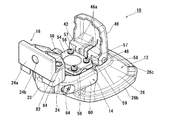
以上の構成の支持具10をダッシュボード等の被吸着面35に装着する手順について説明する。被吸着面35に装着する前は図5に示すように蓋部46を開位置にする。この状態で支持具10を被吸着面35の所望位置に載置する。次いで蓋部46の上方に向いて露出している内面部分46aを指で下方に強く押下して引き棒42を押し下げる。こうすることにより吸盤30の中央部が押し下げられて高分子ゲルシート33と被吸着面35との間の空間86(図1)の空気が排出されて高分子ゲルシート33が被吸着面35に広い面積で粘着する。このときの状態を図6に示す。この状態からさらに蓋部46を図1に示すように閉位置に回動させることにより、カム部57(図5、図6、図7)が金属板59の表面に当接して引き棒42が吸盤30の中央部を伴って引き上げられて高分子ゲルシート33と被吸着面35との間の空間86が負圧化されて吸着力が発生する。これにより支持具10は被吸着面35に強く装着された状態となる。この状態では図7に示すように、運転者等が手動操作で回動部14を回動軸18を中心に回動させることによりモニタ装置25の高さ位置を調整することができる。この場合回動部14は上方に突出した蓋部46を跨ぐように配置されているので、回動部14を回動させると回動部14の枠内に構成される空洞87に蓋部46が入り込む。したがって回動部14は蓋部46に当たることなく広い角度範囲で回動することができる。この実施の形態の設計では回動軸18を中心とした回動部14の回動範囲は、被吸着面35に平行な位置から上方に90°以上、下方に25°で、全体としては115°以上に設定されている。また回動軸20を中心としたモニタ取付部16の回動範囲は回動軸18を中心とした回動部14の回動範囲よりもさらに広く設定されている。したがって回動軸18を中心とした回動部14の回動と回動軸20を中心としたモニタ取付部16の回動との協働により、モニタ装置25を被吸着面35に対し直角の姿勢に維持したまま回動部14を115°以上回動させることができるので、モニタ装置25の高さ位置を広い範囲で調整することができる。また据付部24を第二回動部22のピボット23(図1)を中心に傾動させることによりモニタ装置25の傾きを調整することができる。すなわち据付部24の傾動動作により、モニタ装置25は少なくとも、支持具10の前後方向に延びる軸21(図1、図3)の軸回り方向に傾動自在となり、ダッシュボード等の被吸着面35が傾いていてもモニタ装置25を水平に保つことができる。支持具10を被吸着面35から外すときは、カバー26の外周位置に形成されている隆起部26cに指をかけてカバー26を持ち上げ、隆起部26cの側方の開口部26d(図7)から指を指し入れて吸盤30ごと高分子ゲルシート33を被吸着面35から引き剥がす。   A procedure for mounting the support 10 having the above configuration on the suction surface 35 such as a dashboard will be described. Prior to mounting on the suction surface 35, the lid 46 is set to the open position as shown in FIG. In this state, the support 10 is placed at a desired position on the attracted surface 35. Next, the inner surface portion 46a exposed to the upper side of the lid portion 46 is strongly pressed downward with a finger to push down the pull bar 42. By doing so, the central portion of the suction cup 30 is pushed down, the air in the space 86 (FIG. 1) between the polymer gel sheet 33 and the surface to be adsorbed 35 is discharged, and the polymer gel sheet 33 has a wide area on the surface to be adsorbed 35. Adhere with. The state at this time is shown in FIG. From this state, the lid portion 46 is further rotated to the closed position as shown in FIG. 1, so that the cam portion 57 (FIGS. 5, 6, and 7) abuts on the surface of the metal plate 59 and the pull bar 42 is moved. The space 86 between the polymer gel sheet 33 and the surface to be attracted 35 is pulled down with the central portion of the suction cup 30 and the suction force is generated. As a result, the support 10 is strongly attached to the attracted surface 35. In this state, as shown in FIG. 7, the driver or the like can manually adjust the height position of the monitor device 25 by rotating the rotation unit 14 about the rotation shaft 18. In this case, since the rotating portion 14 is disposed so as to straddle the lid portion 46 that protrudes upward, when the rotating portion 14 is rotated, the lid portion 46 is formed in the cavity 87 configured in the frame of the rotating portion 14. Enters. Therefore, the rotation part 14 can rotate in a wide angle range without hitting the lid part 46. In the design of this embodiment, the rotation range of the rotation unit 14 around the rotation shaft 18 is 90 ° or more upward and 25 ° downward from a position parallel to the attracted surface 35, and 115 as a whole. It is set to more than °. Further, the rotation range of the monitor mounting portion 16 around the rotation shaft 20 is set wider than the rotation range of the rotation portion 14 around the rotation shaft 18. Therefore, the monitor device 25 is perpendicular to the attracted surface 35 by the cooperation of the rotation of the rotation unit 14 about the rotation axis 18 and the rotation of the monitor mounting unit 16 about the rotation axis 20. Since the rotation unit 14 can be rotated by 115 ° or more while maintaining the posture, the height position of the monitor device 25 can be adjusted in a wide range. Further, the tilt of the monitor device 25 can be adjusted by tilting the installation portion 24 around the pivot 23 (FIG. 1) of the second rotating portion 22. That is, by the tilting operation of the installation part 24, the monitor device 25 can tilt at least around the axis 21 (FIG. 1, FIG. 3) extending in the front-rear direction of the support tool 10. Even if it is inclined, the monitor device 25 can be kept horizontal. When the support 10 is removed from the attracted surface 35, the cover 26 is lifted by placing a finger on the raised portion 26c formed at the outer peripheral position of the cover 26, and the opening 26d on the side of the raised portion 26c (FIG. 7). Then, the finger is pointed in and the polymer gel sheet 33 together with the suction cup 30 is peeled off from the attracted surface 35.

《空気抜き穴の他の配置パターン例》
高分子ゲルシート33における空気抜き穴33aの他の配置パターン例を図8、図9に示す。図8の高分子ゲルシート33は空気抜き穴33aを3つの径方向位置に同心円状に配置している。このうち内周側の空気抜き穴33aは周方向に均等間隔で4個配置されている。中間の径方向位置の空気抜き穴33aは周方向に均等間隔で8個配置されている。内周側の4個の空気抜き穴33aと中間の径方向位置の8個の空気抜き穴33aの一部は同一周方向位置で放射状に配列されている。外周側の空気抜き穴33aは8個配置されている。外周側の空気抜き穴33aと同一径方向位置には周方向に均等の間隔で4個の位置ズレ防止穴33bが形成されている。外周側の8個の空気抜き穴33aと4個の位置ズレ防止穴33bは周方向に均等間隔で配置されている。この空気抜き穴33aの配置パターンによれば、高分子ゲルシート33の全面にわたり空気抜き穴33aが形成されているので、吸盤30の吸着面32と高分子ゲルシート33の間の空気をより確実に抜くことができる。
<Other arrangement patterns of air vent holes>
Other arrangement patterns of the air vent holes 33a in the polymer gel sheet 33 are shown in FIGS. The polymer gel sheet 33 of FIG. 8 has air vent holes 33a arranged concentrically at three radial positions. Among these, four air vent holes 33a on the inner peripheral side are arranged at equal intervals in the circumferential direction. Eight air vent holes 33a at intermediate radial positions are arranged at equal intervals in the circumferential direction. A part of the four air vent holes 33a on the inner peripheral side and the eight air vent holes 33a at the intermediate radial position are arranged radially at the same peripheral position. Eight air vent holes 33a on the outer peripheral side are arranged. Four misalignment prevention holes 33b are formed at equal intervals in the circumferential direction at the same radial position as the air vent hole 33a on the outer peripheral side. The eight air vent holes 33a and the four misalignment prevention holes 33b on the outer peripheral side are arranged at equal intervals in the circumferential direction. According to the arrangement pattern of the air vent holes 33a, since the air vent holes 33a are formed over the entire surface of the polymer gel sheet 33, the air between the suction surface 32 of the suction cup 30 and the polymer gel sheet 33 can be more reliably vented. it can.

図9の高分子ゲルシート33は図4の空気抜き穴33aと位置ズレ防止穴33bの配置に加えて、中央位置に空気抜き穴33aよりも大径の空気抜き穴33aaを形成したものである。この配置パターンよれば吸盤30の吸着面32の中央位置と高分子ゲルシート33の中央位置の間の空気を空気抜き穴33aaを通してより確実に抜くことができる。   The polymer gel sheet 33 of FIG. 9 is formed by forming an air vent hole 33aa having a diameter larger than that of the air vent hole 33a at the center position in addition to the arrangement of the air vent hole 33a and the positional deviation prevention hole 33b of FIG. According to this arrangement pattern, air between the central position of the suction surface 32 of the suction cup 30 and the central position of the polymer gel sheet 33 can be more reliably extracted through the air vent hole 33aa.

《高分子ゲルシートの他の形状例》
高分子ゲルシート33の他の形状例を図10に示す。この高分子ゲルシート33は吸盤30の形状をカバー26の凹所28(図1)の開口端形状に合わせて非円形に構成した場合に適合するように構成したものである。すなわち高分子ゲルシート33は非円形の吸盤30の形状に重なるように非円形に構成されている。吸盤30にはカバー26の隆起部26cの開口部26d(図7)内に配置されるべろ部(図示せず)が形成され、高分子ゲルシート33にも吸盤30のべろ部に重なるようにべろ部33cが形成されている。これによれば、支持具10を被吸着面35から外すためにカバー26の外周位置に形成されている隆起部26cに指をかけてカバー26を持ち上げ、隆起部26cの側方の開口部26d(図7)から指を指し入れたときに、すぐに高分子ゲルシート33のべろ部33cに指が掛かるので、べろ部33cから剥がし始めて高分子ゲルシート33全体を被吸着面35から容易に剥がすことができる。。
<< Other shapes of polymer gel sheet >>
Another example of the shape of the polymer gel sheet 33 is shown in FIG. This polymer gel sheet 33 is configured so as to be adapted when the shape of the suction cup 30 is configured to be non-circular in accordance with the opening end shape of the recess 28 (FIG. 1) of the cover 26. That is, the polymer gel sheet 33 is configured in a non-circular shape so as to overlap the shape of the non-circular suction cup 30. A suction part (not shown) is formed in the suction cup 30 so as to be disposed in the opening 26d (FIG. 7) of the raised part 26c of the cover 26, and the polymer gel sheet 33 is also covered with the suction part of the suction cup 30. A portion 33c is formed. According to this, in order to remove the support tool 10 from the attracted surface 35, the cover 26 is lifted by placing a finger on the raised portion 26c formed at the outer peripheral position of the cover 26, and the opening 26d on the side of the raised portion 26c. When the finger is pointed from (FIG. 7), the finger is immediately applied to the labyrinth portion 33c of the polymer gel sheet 33, so that the entire polymer gel sheet 33 is easily peeled from the attracted surface 35 by starting to peel off from the ladle portion 33c Can do. .

前記実施の形態では位置ズレ防止穴33bを貫通孔で構成したが、これに代えて非貫通孔である位置ズレ防止凹部として構成することもできる。また前記実施の形態ではこの発明の吸盤装置を車載モニタ装置の支持具に適用した場合について説明したが、この発明の吸盤装置は車載モニタ装置の支持具以外の各種用途に適用することもできる。   In the above-described embodiment, the misalignment prevention hole 33b is configured as a through hole. Alternatively, it can be configured as a misalignment prevention recess that is a non-through hole. Moreover, although the said embodiment demonstrated the case where the suction cup apparatus of this invention was applied to the support tool of a vehicle-mounted monitor apparatus, the suction cup apparatus of this invention can also be applied to various uses other than the support tool of a vehicle-mounted monitor apparatus.

この発明の吸盤装置を車載モニタ装置の支持具に適用した実施の形態を示す図で、図3のA−A矢視断面図である。It is a figure which shows embodiment which applied the suction cup apparatus of this invention to the support tool of a vehicle-mounted monitor apparatus, and is AA arrow sectional drawing of FIG. 図1の支持具の斜視図である。It is a perspective view of the support tool of FIG. 図1の支持具の平面図である。It is a top view of the support tool of FIG. 図1の支持具の高分子ゲルシート33における空気抜き穴33aと位置ズレ防止穴33bの配置パターン例を示す図で、(a)は平面図、(b)は(a)のB−B矢視断面図である。It is a figure which shows the example of arrangement | positioning pattern of the air vent hole 33a and the position shift prevention hole 33b in the polymer gel sheet 33 of the support of FIG. 1, (a) is a top view, (b) is a BB arrow cross section of (a). FIG. 図1の支持具を蓋部46を開いた状態で示す斜視図である。It is a perspective view which shows the support tool of FIG. 1 in the state which opened the cover part 46. FIG. 図1の支持具を被吸着面35に載置して引き棒42を押し下げたときの状態を示す断面図である。FIG. 3 is a cross-sectional view showing a state when the support tool of FIG. 図1の支持具の側面図である。It is a side view of the support tool of FIG. 図1の支持具の高分子ゲルシート33における空気抜き穴33aの他の配置パターン例を示す図で、(a)は平面図、(b)は(a)のC−C矢視断面図である。It is a figure which shows the other example of arrangement | positioning pattern of the air vent hole 33a in the polymer gel sheet 33 of the support of FIG. 1, (a) is a top view, (b) is CC sectional view taken on the line of (a). 図1の支持具の高分子ゲルシート33における空気抜き穴33aの他の配置パターン例を示す図で、(a)は平面図、(b)は(a)のD−D矢視断面図である。It is a figure which shows the other example of arrangement | positioning pattern of the air vent hole 33a in the polymer gel sheet 33 of the support tool of FIG. 1, (a) is a top view, (b) is a DD arrow sectional drawing of (a). 図1の支持具の高分子ゲルシート33の他の形状例を示す図で、(a)は平面図、(b)は(a)のE−E矢視断面図である。It is a figure which shows the other example of a shape of the polymer gel sheet 33 of the support tool of FIG. 1, (a) is a top view, (b) is EE arrow sectional drawing of (a).

符号の説明Explanation of symbols

30…吸盤、30a…位置ズレ防止凸部、32…吸着面、33…高分子ゲルシート(粘着性のある高分子ゲル層)、33a,33aa…空気抜き穴、33b…位置ズレ防止穴   30 ... Suction cup, 30a ... Misalignment prevention convex part, 32 ... Adsorption surface, 33 ... Polymer gel sheet (adhesive polymer gel layer), 33a, 33aa ... Air vent hole, 33b ... Misalignment prevention hole

Claims (5)

吸盤の吸着面の周方向に異なる複数位置および径方向に異なる複数位置に対応する複数の位置にそれぞれ空気抜き穴を開設した粘着性のある高分子ゲル層を該吸着面に着脱自在に貼り付けてなる吸盤装置。   Adhesive polymer gel layers with air vent holes opened at a plurality of positions corresponding to a plurality of positions different in the circumferential direction of the suction surface of the suction cup and a plurality of positions different in the radial direction are detachably attached to the suction surface. Suction cup device. 前記高分子ゲル層に前記複数個の空気抜き穴が同心円状に配列されている請求項1記載の吸盤装置。   The suction cup device according to claim 1, wherein the plurality of air vent holes are concentrically arranged in the polymer gel layer. 前記高分子ゲル層に前記複数個の空気抜き穴が放射状に配列されている請求項1または2記載の吸盤装置。   The suction cup device according to claim 1 or 2, wherein the plurality of air vent holes are radially arranged in the polymer gel layer. 前記高分子ゲル層の中央位置に空気抜き穴が開設されている請求項1から3のいずれか1つに記載の吸盤装置。   The suction cup device according to any one of claims 1 to 3, wherein an air vent hole is formed at a central position of the polymer gel layer. 前記吸盤の吸着面の周方向に異なる複数位置に位置ズレ防止凸部が形成され、前記高分子ゲル層に該位置ズレ防止凸部が嵌り込む位置ズレ防止穴または位置ズレ防止凹部が形成されている請求項1から4のいずれか1つに記載の吸盤装置。   A misalignment prevention convex portion is formed at a plurality of different positions in the circumferential direction of the suction surface of the suction cup, and a misalignment prevention hole or a misalignment prevention concave portion into which the misalignment prevention convex portion is fitted is formed in the polymer gel layer. The suction cup device according to any one of claims 1 to 4.
JP2008243443A 2008-09-23 2008-09-23 Suction cup device Expired - Fee Related JP4897973B2 (en)

Priority Applications (1)

Application Number Priority Date Filing Date Title
JP2008243443A JP4897973B2 (en) 2008-09-23 2008-09-23 Suction cup device

Applications Claiming Priority (1)

Application Number Priority Date Filing Date Title
JP2008243443A JP4897973B2 (en) 2008-09-23 2008-09-23 Suction cup device

Publications (2)

Publication Number Publication Date
JP2010077977A true JP2010077977A (en) 2010-04-08
JP4897973B2 JP4897973B2 (en) 2012-03-14

Family

ID=42208665

Family Applications (1)

Application Number Title Priority Date Filing Date
JP2008243443A Expired - Fee Related JP4897973B2 (en) 2008-09-23 2008-09-23 Suction cup device

Country Status (1)

Country Link
JP (1) JP4897973B2 (en)

Cited By (3)

* Cited by examiner, † Cited by third party
Publication number Priority date Publication date Assignee Title
CN109147567A (en) * 2018-11-07 2019-01-04 深圳市中银科技有限公司 A kind of anti-down vertical advertising machine
JP2019527804A (en) * 2016-08-09 2019-10-03 チャン、ジン テJANG, Jin Tae Adsorption device
JP2021139430A (en) * 2020-03-04 2021-09-16 セキセイ株式会社 pedestal

Citations (5)

* Cited by examiner, † Cited by third party
Publication number Priority date Publication date Assignee Title
JPS5586113A (en) * 1978-12-23 1980-06-28 Fujitsu Ltd Vapor phase growth process
JPH11230149A (en) * 1998-02-17 1999-08-27 Masayuki Inami Suction cup having gel sheet packing
JP2000116740A (en) * 1998-10-09 2000-04-25 Shiseido Co Ltd Roller type massaging appliance
JP2000245619A (en) * 1999-02-26 2000-09-12 Mitsubishi Electric Corp Rice cooker
JP2007285485A (en) * 2006-04-20 2007-11-01 Sony Corp Suction cup device

Patent Citations (5)

* Cited by examiner, † Cited by third party
Publication number Priority date Publication date Assignee Title
JPS5586113A (en) * 1978-12-23 1980-06-28 Fujitsu Ltd Vapor phase growth process
JPH11230149A (en) * 1998-02-17 1999-08-27 Masayuki Inami Suction cup having gel sheet packing
JP2000116740A (en) * 1998-10-09 2000-04-25 Shiseido Co Ltd Roller type massaging appliance
JP2000245619A (en) * 1999-02-26 2000-09-12 Mitsubishi Electric Corp Rice cooker
JP2007285485A (en) * 2006-04-20 2007-11-01 Sony Corp Suction cup device

Cited By (4)

* Cited by examiner, † Cited by third party
Publication number Priority date Publication date Assignee Title
JP2019527804A (en) * 2016-08-09 2019-10-03 チャン、ジン テJANG, Jin Tae Adsorption device
CN109147567A (en) * 2018-11-07 2019-01-04 深圳市中银科技有限公司 A kind of anti-down vertical advertising machine
JP2021139430A (en) * 2020-03-04 2021-09-16 セキセイ株式会社 pedestal
JP7385922B2 (en) 2020-03-04 2023-11-24 セキセイ株式会社 pedestal

Also Published As

Publication number Publication date
JP4897973B2 (en) 2012-03-14

Similar Documents

Publication Publication Date Title
JP4254846B2 (en) Suction cup device
US8356781B2 (en) Suction device
JP4802938B2 (en) Suction cup device
JP4897973B2 (en) Suction cup device
JP2008051286A (en) Sucker
EP2796302B1 (en) Bead breaking unit for tyre changing machines
JP2008064264A (en) Sucker device
JP4837022B2 (en) Suction cup device
JP2010127400A (en) On-vehicle monitor support device
JP5156561B2 (en) Monitor device support
JP2012192866A (en) Removing method of tire upper bead and tire attaching-detaching device
JP3963363B2 (en) Wheel sheet pasting device and sheet feeding device
JP4818347B2 (en) Suction cup device
JP5125687B2 (en) Suction cup and suction cup device
JP5352778B2 (en) Mounting device and device for in-vehicle equipment
JP2010143431A (en) Monitor stand
JP4903832B2 (en) On-vehicle equipment fittings and equipment
JP2011137508A (en) Stand device
JP4840430B2 (en) Suction cup device
JP2007132411A (en) Support for on-vehicle receiver
CN102192232B (en) Suction disc device
JP2016168898A (en) Tire mounting/demounting clip, tire demounting method and tire mounting method
JP5167506B2 (en) Pedestal with dummy cover for mounting on-vehicle equipment
JP2010066385A (en) Stand device
JP2005199845A (en) Mounting device for on-vehicle display device

Legal Events

Date Code Title Description
A621 Written request for application examination

Free format text: JAPANESE INTERMEDIATE CODE: A621

Effective date: 20100913

A977 Report on retrieval

Free format text: JAPANESE INTERMEDIATE CODE: A971007

Effective date: 20110725

A131 Notification of reasons for refusal

Free format text: JAPANESE INTERMEDIATE CODE: A131

Effective date: 20110802

A521 Written amendment

Free format text: JAPANESE INTERMEDIATE CODE: A523

Effective date: 20110928

TRDD Decision of grant or rejection written
A01 Written decision to grant a patent or to grant a registration (utility model)

Free format text: JAPANESE INTERMEDIATE CODE: A01

Effective date: 20111220

A01 Written decision to grant a patent or to grant a registration (utility model)

Free format text: JAPANESE INTERMEDIATE CODE: A01

A61 First payment of annual fees (during grant procedure)

Free format text: JAPANESE INTERMEDIATE CODE: A61

Effective date: 20111223

R150 Certificate of patent (=grant) or registration of utility model

Free format text: JAPANESE INTERMEDIATE CODE: R150

FPAY Renewal fee payment (prs date is renewal date of database)

Free format text: PAYMENT UNTIL: 20150106

Year of fee payment: 3

FPAY Renewal fee payment (prs date is renewal date of database)

Free format text: PAYMENT UNTIL: 20150106

Year of fee payment: 3

LAPS Cancellation because of no payment of annual fees