JP2010077945A - Multi-cylinder engine - Google Patents
Multi-cylinder engine Download PDFInfo
- Publication number
- JP2010077945A JP2010077945A JP2008249735A JP2008249735A JP2010077945A JP 2010077945 A JP2010077945 A JP 2010077945A JP 2008249735 A JP2008249735 A JP 2008249735A JP 2008249735 A JP2008249735 A JP 2008249735A JP 2010077945 A JP2010077945 A JP 2010077945A
- Authority
- JP
- Japan
- Prior art keywords
- passage
- egr gas
- egr
- intake
- intake air
- Prior art date
- Legal status (The legal status is an assumption and is not a legal conclusion. Google has not performed a legal analysis and makes no representation as to the accuracy of the status listed.)
- Granted
Links
Images


Classifications
-
- Y—GENERAL TAGGING OF NEW TECHNOLOGICAL DEVELOPMENTS; GENERAL TAGGING OF CROSS-SECTIONAL TECHNOLOGIES SPANNING OVER SEVERAL SECTIONS OF THE IPC; TECHNICAL SUBJECTS COVERED BY FORMER USPC CROSS-REFERENCE ART COLLECTIONS [XRACs] AND DIGESTS
- Y02—TECHNOLOGIES OR APPLICATIONS FOR MITIGATION OR ADAPTATION AGAINST CLIMATE CHANGE
- Y02T—CLIMATE CHANGE MITIGATION TECHNOLOGIES RELATED TO TRANSPORTATION
- Y02T10/00—Road transport of goods or passengers
- Y02T10/10—Internal combustion engine [ICE] based vehicles
- Y02T10/12—Improving ICE efficiencies
Abstract
Description
本発明は、多気筒エンジンに関し、詳しくは出力性能や排出ガス性能を高めることができる多気筒エンジンに関するものである。 The present invention relates to a multi-cylinder engine, and more particularly to a multi-cylinder engine that can improve output performance and exhaust gas performance.
従来の多気筒エンジンとして、本発明と同様、クランク軸の架設方向を前後方向、クランク軸の架設方向と直交するシリンダヘッドの幅方向を横方向として、シリンダヘッドの横側面に吸気分配通路が設けられ、この吸気分配通路の上方に前から順にEGR弁ケースとEGRガス導入通路と吸気導入管とが配置され、EGR弁ケースの弁ケースガス出口にEGRガス導入通路の導入通路ガス入口が連通され、EGRガス導入通路の導入通路ガス出口が吸気導入管の周壁前側で吸気入口管に連通され、吸気導入管の軸長方向に沿って導入される吸気に吸気導入管の周壁前側から流入するEGRガスが混入され、このEGRガスが混入された吸気が吸気分配通路で各気筒の吸気ポートに分配されるようにしたものがある(例えば、特許文献1参照)。 As a conventional multi-cylinder engine, as in the present invention, an intake distribution passage is provided on the side surface of the cylinder head, with the crankshaft installation direction being the front-rear direction and the width direction of the cylinder head perpendicular to the crankshaft installation direction being the horizontal direction An EGR valve case, an EGR gas introduction passage, and an intake introduction pipe are arranged in order from the front above the intake distribution passage, and the introduction passage gas inlet of the EGR gas introduction passage communicates with the valve case gas outlet of the EGR valve case. The EGR gas introduction passage has an introduction passage gas outlet that communicates with the intake inlet pipe on the front side of the peripheral wall of the intake pipe, and flows into the intake air that is introduced along the axial length direction of the intake pipe from the front side of the peripheral wall of the intake pipe There is one in which gas is mixed and the intake air mixed with the EGR gas is distributed to the intake port of each cylinder in an intake distribution passage (see, for example, Patent Document 1).
しかし、従来の多気筒エンジンは、EGR弁ケースの弁ケースガス出口からEGRガス導入通路内に弁装着フレームが突出され、この弁取り付けフレームにEGRガス導入通路からEGR弁ケースへのEGRガスの逆流を阻止するリード弁が取り付けられ、リード弁の下流のEGRガス導入通路の距離が短く、EGRガスの整流機能がないため、問題がある。 However, in the conventional multi-cylinder engine, the valve mounting frame protrudes from the valve case gas outlet of the EGR valve case into the EGR gas introduction passage, and the EGR gas flows backward from the EGR gas introduction passage to the EGR valve case in the valve mounting frame. There is a problem because a reed valve for preventing the EGR gas is attached, the distance of the EGR gas introduction passage downstream of the reed valve is short, and there is no EGR gas rectifying function.
上記従来技術では、次の問題がある。
《問題》 出力性能や排出ガス性能が悪化することがある。
出力性能や排気ガス性能が悪化することがある。
その理由は、次のように推定される。
EGR弁ケースの弁ケースガス出口からEGRガス導入通路内に弁取り付けフレームが突出され、この弁取り付けフレームにEGRガス導入通路からEGR弁ケースへのEGRガスの逆流を阻止するリード弁が取り付けられ、リード弁の下流のEGRガス導入通路の距離が短く、EGRガスの整流機能がないため、リード弁を通過した直後のEGRガスは、方向が揃わないまま吸気導入管に流入する。このため、吸気導入管の径方向に沿うEGRガスの貫通力が弱く、EGRガスはEGRガス入口付近のみで吸気に混入され、EGRガスが吸気全体に均一に分散されず、各気筒に供給される吸気中のEGRガス濃度が異なり、出力性能や排出ガス性能が悪化する。
The above prior art has the following problems.
<Problem> Output performance and exhaust gas performance may deteriorate.
Output performance and exhaust gas performance may deteriorate.
The reason is estimated as follows.
A valve mounting frame protrudes from the valve case gas outlet of the EGR valve case into the EGR gas introduction passage, and a reed valve for preventing a reverse flow of EGR gas from the EGR gas introduction passage to the EGR valve case is attached to the valve mounting frame. Since the distance of the EGR gas introduction passage downstream of the reed valve is short and there is no EGR gas rectifying function, the EGR gas immediately after passing through the reed valve flows into the intake introduction pipe without aligning the direction. For this reason, the penetration force of the EGR gas along the radial direction of the intake pipe is weak, and the EGR gas is mixed into the intake air only near the EGR gas inlet, and the EGR gas is not uniformly distributed throughout the intake air and is supplied to each cylinder. The EGR gas concentration in the intake air differs and the output performance and exhaust gas performance deteriorate.
本発明は、上記問題点を解決することができる多気筒エンジン、すなわち、出力性能や排出ガス性能を高めることができる多気筒エンジンを提供することを課題とする。 An object of the present invention is to provide a multi-cylinder engine that can solve the above-described problems, that is, a multi-cylinder engine that can improve output performance and exhaust gas performance.
請求項1に係る発明の発明特定事項は、次の通りである。
クランク軸(1)の架設方向を前後方向、クランク軸(1)の架設方向と直交するシリンダヘッド(2)の幅方向を横方向として、
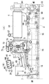
図1(A)に例示するように、シリンダヘッド(2)の横側面に吸気分配通路(3)が設けられ、この吸気分配通路(3)の上方に前から順にEGR弁ケース(5)とEGRガス導入通路(6)と吸気導入管(7)とが配置され、EGR弁ケース(5)の弁ケースガス出口(10)にEGRガス導入通路(6)の導入通路ガス入口(11)が連通され、EGRガス導入通路(6)の導入通路ガス出口(12)が吸気導入管(7)の周壁前側で吸気導入管(7)内に連通され、
吸気導入管(7)の軸長方向に沿って導入される吸気(14)に吸気導入管(7)の周壁前側から流入するEGRガス(15)が混入され、このEGRガス(15)が混入された吸気(14)が吸気分配通路(3)で各気筒の吸気ポート(16)(16)に分配されるようにした、多気筒エンジンにおいて、
図1(A)に例示するように、EGRガス導入通路(6)からEGR弁ケース(5)へのEGRガス(15)の逆流を阻止するリード弁(17)の下流で、EGRガス導入通路(6)が前後方向に向けられた整流板(39)を備え、EGRガス(15)が整流板(39)に沿って後直進方向に整流されながら、吸気導入管(7)に案内されるようにした、ことを特徴とする多気筒エンジン。
Invention specific matters of the invention according to
The installation direction of the crankshaft (1) is the front-rear direction, and the width direction of the cylinder head (2) perpendicular to the installation direction of the crankshaft (1) is the lateral direction.
As illustrated in FIG. 1 (A), an intake distribution passage (3) is provided on the lateral side surface of the cylinder head (2), and an EGR valve case (5) is disposed above the intake distribution passage (3) in order from the front. An EGR gas introduction passage (6) and an intake introduction pipe (7) are arranged, and an introduction passage gas inlet (11) of the EGR gas introduction passage (6) is connected to the valve case gas outlet (10) of the EGR valve case (5). The inlet passage gas outlet (12) of the EGR gas inlet passage (6) communicates with the intake inlet pipe (7) on the front side of the peripheral wall of the inlet inlet pipe (7).
EGR gas (15) flowing from the front side of the peripheral wall of the intake air introduction pipe (7) is mixed into the intake air (14) introduced along the axial length direction of the intake air introduction pipe (7), and this EGR gas (15) is mixed. In the multi-cylinder engine in which the intake air (14) is distributed to the intake ports (16) and (16) of each cylinder in the intake air distribution passage (3),
As illustrated in FIG. 1A, the EGR gas introduction passage is provided downstream of the reed valve (17) for preventing the backflow of the EGR gas (15) from the EGR gas introduction passage (6) to the EGR valve case (5). (6) includes a rectifying plate (39) oriented in the front-rear direction, and the EGR gas (15) is guided to the intake air introduction pipe (7) while being rectified in the straight forward direction along the rectifying plate (39). A multi-cylinder engine characterized by that.
(請求項1に係る発明)
《効果》 出力性能や排出ガス性能を高めることができる。
出力性能や排出ガス性能を高めることができる。その理由は、次のように推定される。
図1(A)に例示するように、EGRガス導入通路(6)からEGR弁ケース(5)へのEGRガス(15)の逆流を阻止するリード弁(17)の下流で、EGRガス導入通路(6)が前後方向に向けられた整流板(39)を備え、EGRガス(15)が整流板(39)に沿って後直進方向に整流されながら、吸気導入管(7)に案内されるようにしたので、リード弁(17)を通過したEGRガス(15)が、EGRガス導入通路(6)でその方向を揃えられてから、導入通路ガス出口(12)から吸気導入管(7)に流入する。このため、吸気導入管(7)の径方向に沿うEGRガス(15)の貫通力が強く、EGRガス(15)は吸気導入管(7)の径方向の広い範囲で吸気(14)に混入され、EGRガス(15)が吸気(14)全体に均一に分散され、各気筒に供給される吸気(14)中のEGRガス(15)の濃度が均等化され、出力性能や排出ガス性能を高めることができる。
(Invention according to Claim 1)
<Effect> Output performance and exhaust gas performance can be improved.
Output performance and exhaust gas performance can be improved. The reason is estimated as follows.
As illustrated in FIG. 1A, the EGR gas introduction passage is provided downstream of the reed valve (17) for preventing the backflow of the EGR gas (15) from the EGR gas introduction passage (6) to the EGR valve case (5). (6) includes a rectifying plate (39) oriented in the front-rear direction, and the EGR gas (15) is guided to the intake air introduction pipe (7) while being rectified in the straight forward direction along the rectifying plate (39). Since the EGR gas (15) having passed through the reed valve (17) is aligned in the direction of the EGR gas introduction passage (6), the intake introduction pipe (7) is introduced from the introduction passage gas outlet (12). Flow into. Therefore, the penetration force of the EGR gas (15) along the radial direction of the intake air intake pipe (7) is strong, and the EGR gas (15) is mixed into the intake air (14) in a wide range in the radial direction of the intake air intake pipe (7). The EGR gas (15) is uniformly distributed throughout the intake air (14), the concentration of the EGR gas (15) in the intake air (14) supplied to each cylinder is equalized, and the output performance and exhaust gas performance are improved. Can be increased.
(請求項2に係る発明)
請求項1に係る発明の効果に加え、次の効果を奏する。
《効果》 出力性能や排出ガス性能を高める機能が高い。
出力性能や排出ガス性能を高める機能が高い。
その理由は、次のように推定される。
図1(A)(B)に例示するように、整流板(39)が、EGRガス導入通路(6)の上壁(40)から下向きに突出される複数枚の下向き整流板(41)と、EGRガス導入通路(6)の下壁(42)から上向きに突出される複数枚の上向き整流板(43)とで構成されているため、EGRガス(15)はEGRガス導入通路(6)の上側と下側の両方で整流され、吸気導入管(7)の径方向に沿うEGRガス(15)の貫通力が強まる。
また、図1(B)に例示するように、下向き整流板(41)で区分される上側区分通路(44)と上向き整流板(43)で区分される下側区分通路(45)とからなる各区分通路(46)が、上側区分通路(44)の下開口(47)と下側区分通路(45)の上開口(48)とを介して相互に連通されているので、各区分通路(46)を通過するEGRガス量が均等化される。
これらの理由により、EGRガス(15)が吸気導入管(7)を通過する吸気(14)全体に均一に分散し、各気筒に供給される吸気(14)中のEGRガス濃度が均等化され、出力性能や排出ガス性能を高めることができる。
(Invention according to Claim 2)
In addition to the effect of the invention according to
<Effect> High function to enhance output performance and exhaust gas performance.
High function to enhance output performance and exhaust gas performance.
The reason is estimated as follows.
As illustrated in FIGS. 1A and 1B, a rectifying plate (39) includes a plurality of downward rectifying plates (41) protruding downward from the upper wall (40) of the EGR gas introduction passage (6). The EGR gas introduction passage (6) is composed of a plurality of upward rectifying plates (43) protruding upward from the lower wall (42) of the EGR gas introduction passage (6), so that the EGR gas (15) is the EGR gas introduction passage (6). Is rectified on both the upper side and the lower side, and the penetration force of the EGR gas (15) along the radial direction of the intake air introduction pipe (7) is strengthened.
Further, as illustrated in FIG. 1 (B), an upper section passage (44) divided by a downward rectifying plate (41) and a lower section passage (45) divided by an upward rectifying plate (43). Since each section passage (46) communicates with each other via the lower opening (47) of the upper section passage (44) and the upper opening (48) of the lower section passage (45), each section passage ( The amount of EGR gas passing through 46) is equalized.
For these reasons, the EGR gas (15) is uniformly dispersed throughout the intake air (14) passing through the intake air intake pipe (7), and the EGR gas concentration in the intake air (14) supplied to each cylinder is equalized. , Output performance and exhaust gas performance can be enhanced.
(請求項3に係る発明)
請求項2に係る発明の効果に加え、次の効果を奏する。
《効果》 出力性能や排出ガス性能を高める機能が高い。
出力性能や排出ガス性能を高める機能が高い。
その理由は、次のように推定される。
図1(B)に例示するように、下向き整流板(41)が下側区分通路(45)に向けて突出され、上向き整流板(43)が上側区分通路(44)に向けて突出されているので、下向き整流板(41)と上向き整流板(43)が相互突合せ状に突出される場合に比べ、下向き整流板(41)と上向き整流板(43)の突出端相互間の隙間を大きくすることができ、この隙間を介して各区分通路(46)を通過するEGRガス量が均等化され、EGRガス(15)が吸気導入管(7)を通過する吸気(14)全体に均一に分散し、各気筒に供給される吸気(14)中のEGRガス濃度が均等化され、出力性能や排出ガス性能を高めることができる。
(Invention according to claim 3)
In addition to the effect of the invention according to
<Effect> High function to enhance output performance and exhaust gas performance.
High function to enhance output performance and exhaust gas performance.
The reason is estimated as follows.
As illustrated in FIG. 1B, the downward rectifying plate (41) protrudes toward the lower section passage (45), and the upward rectifying plate (43) protrudes toward the upper section passage (44). Therefore, the gap between the projecting ends of the downward rectifying plate (41) and the upward rectifying plate (43) is larger than when the downward rectifying plate (41) and the upward rectifying plate (43) are projected in abutment with each other. Through this gap, the amount of EGR gas passing through each section passage (46) is equalized, and the EGR gas (15) is uniformly distributed throughout the intake air (14) passing through the intake air intake pipe (7). Dispersed and the EGR gas concentration in the intake air (14) supplied to each cylinder is equalized, and the output performance and exhaust gas performance can be improved.
本発明の実施の形態を図面に基づいて説明する。図1から図8は本発明の実施形態に係る多気筒エンジンを説明する図で、この実施形態では、立形4気筒ディーゼルエンジンについて説明する。 Embodiments of the present invention will be described with reference to the drawings. 1 to 8 are diagrams for explaining a multi-cylinder engine according to an embodiment of the present invention. In this embodiment, a vertical four-cylinder diesel engine will be explained.
本発明の実施形態の概要は、次の通りである。
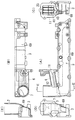
図6に示すように、シリンダブロック(61)の上部にシリンダヘッド(2)が組み付けられ、シリンダブロック(61)の下部にオイルパン(62)が組み付けられ、シリンダブロック(61)の前部に水ポンプ(63)とオイルポンプ(64)とが組み付けられ、シリンダブロック(61)の後部にフライホイルハウジング(65)が組み付けられている。
シリンダブロック(61)の下部に形成されたクランクケース(66)内にはクランク軸(1)が架設されている。
The outline of the embodiment of the present invention is as follows.
As shown in FIG. 6, the cylinder head (2) is assembled to the upper part of the cylinder block (61), the oil pan (62) is assembled to the lower part of the cylinder block (61), and the front of the cylinder block (61) is assembled. A water pump (63) and an oil pump (64) are assembled, and a flywheel housing (65) is assembled at the rear of the cylinder block (61).
A crankshaft (1) is installed in a crankcase (66) formed in the lower part of the cylinder block (61).
クランク軸(1)の架設方向を前後方向、クランク軸(1)の架設方向と直交するシリンダヘッド(2)の幅方向を横方向とする。
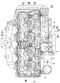
図5に示すように、シリンダヘッド(2)の両横側面の一方に排気合流通路(67)が、他方に吸気分配通路(3)が設けられている。排気合流通路(67)は排気合流通路壁(68)内に設けられ、吸気分配通路(3)は吸気分配通路壁(69)内に設けられている。図1(A)に示すように、吸気分配通路壁(69)は、各気筒の吸気ポート(16)に吸気を分配するためのもので、いわゆる吸気マニホルドといわれるものであるが、図3(A)〜(E)、図4に示すように、この実施形態のものは枝管を備えていない箱形のものであるため、吸気分配通路壁(69)及び吸気分配通路(3)と称している。図5に示すように、排気合流通路(67)は、各気筒の排気ポート(70)からの排気を合流させるためのもので、排気合流通路壁(68)はいわゆる排気マニホルドといわれるものであるが、吸気分配通路壁(69)という部品名と整合させるため排気合流通路壁(68)及び排気合流通路(67)と称している。
The installation direction of the crankshaft (1) is the front-rear direction, and the width direction of the cylinder head (2) perpendicular to the installation direction of the crankshaft (1) is the lateral direction.
As shown in FIG. 5, an exhaust merging passage (67) is provided on one of the lateral sides of the cylinder head (2), and an intake air distribution passage (3) is provided on the other side. The exhaust merge passage (67) is provided in the exhaust merge passage wall (68), and the intake distribution passage (3) is provided in the intake distribution passage wall (69). As shown in FIG. 1 (A), the intake distribution passage wall (69) is used to distribute intake air to the intake port (16) of each cylinder, and is called a so-called intake manifold. As shown in FIGS. 4 (A) to (E) and FIG. 4, this embodiment has a box shape without branch pipes, and is therefore referred to as an intake distribution passage wall (69) and an intake distribution passage (3). ing. As shown in FIG. 5, the exhaust merging passage (67) is for merging exhaust from the exhaust port (70) of each cylinder, and the exhaust merging passage wall (68) is a so-called exhaust manifold. However, they are referred to as an exhaust merging passage wall (68) and an exhaust merging passage (67) in order to match the part name of the intake distribution passage wall (69).
EGR装置の構成は、次の通りである。
図1(A)に示すように、EGR弁ケース(5)にEGR弁(71)を収容し、このEGR弁(71)を開弁して、排気側から吸気分配通路(3)にEGRガス(15)を還流させるようにしている。EGR弁(71)は弁バネ(72)のバネ力で閉弁方向に付勢され、EGR弁(71)がニューマチック式の弁アクチュエータ(73)に連携され、この弁アクチュエータ(73)の吸気圧室(74)が吸気分配通路(3)に連通され、この吸気分配通路(3)に排気エネルギーで駆動される過給機(75)により過給が行われている。図6、図7に示すように、吸気分配通路(3)へは吸気供給パイプ(95)を介して過給がなされている。
The configuration of the EGR device is as follows.
As shown in FIG. 1 (A), an EGR valve (71) is accommodated in an EGR valve case (5), the EGR valve (71) is opened, and an EGR gas is supplied from the exhaust side to the intake distribution passage (3). (15) is refluxed. The EGR valve (71) is biased in the valve closing direction by the spring force of the valve spring (72), and the EGR valve (71) is linked to the pneumatic valve actuator (73). The air pressure chamber (74) communicates with the intake air distribution passage (3), and the intake air distribution passage (3) is supercharged by a supercharger (75) driven by exhaust energy. As shown in FIGS. 6 and 7, the intake air distribution passage (3) is supercharged via an intake air supply pipe (95).
図5に示すように、弁アクチュエータ(73)の吸気圧室(74)が吸気圧導入パイプ(76)を介して吸気分配通路(3)に連通され、この吸気圧導入パイプ(76)に感温作動性の吸気圧遮断弁(77)が配置され、エンジン温度が所定値未満の冷間始動時には、吸気圧遮断弁(77)が閉弁され、吸気分配通路(3)内の過給圧に拘わらず、EGR弁(71)が全閉状態に維持され、エンジン温度が所定値以上の温間始動時や通常運転時には、吸気圧遮断弁(77)が開弁され、吸気分配通路(3)内の過給圧に応じてEGR弁(71)の開度が調節されるようにしている。
この吸気圧遮断弁(77)がEGR弁ケース(5)に取り付けられ、吸気圧遮断弁(77)の入熱部(78)がEGR弁ケース(5)内の弁冷却水路(79)に臨んでいる。吸気圧遮断弁(77)は、内部にバイメタル等の感温性変形手段を備え、その温度による変形を駆動力として弁を開閉する。図5に示す弁冷却水路(79)は平面視でコの字状に形成されている。
As shown in FIG. 5, the intake pressure chamber (74) of the valve actuator (73) is communicated with the intake distribution passage (3) via the intake pressure introduction pipe (76), and the intake pressure introduction pipe (76) is sensed. At the time of cold start when the engine temperature is less than a predetermined value, the intake pressure cutoff valve (77) is closed and the boost pressure in the intake distribution passage (3) is arranged. Regardless of this, the EGR valve (71) is maintained in the fully closed state, and the intake pressure shut-off valve (77) is opened at the time of warm start when the engine temperature is equal to or higher than a predetermined value or during normal operation, and the intake distribution passage (3 The opening degree of the EGR valve (71) is adjusted according to the supercharging pressure in the bracket.
The intake pressure cutoff valve (77) is attached to the EGR valve case (5), and the heat input portion (78) of the intake pressure cutoff valve (77) faces the valve cooling water passage (79) in the EGR valve case (5). It is out. The intake pressure shut-off valve (77) includes temperature-sensitive deformation means such as bimetal inside, and opens and closes the valve using deformation due to the temperature as a driving force. The valve cooling water channel (79) shown in FIG. 5 is formed in a U shape in plan view.
EGR装置の各部品の配置は次の通りである。
図1(A)に示すように、シリンダヘッド(2)の横側面に吸気分配通路(3)が設けられ、この吸気分配通路(3)の上方に前から順にEGRクーラ(4)とEGR弁ケース(5)とEGRガス導入通路(6)と吸気導入管(7)とが配置され、EGRクーラ(4)のクーラガス出口(8)にEGR弁ケース(5)の弁ケースガス入口(9)が連通され、EGR弁ケース(5)の弁ケースガス出口(10)にEGRガス導入通路(6)の導入通路ガス入口(11)が連通され、EGRガス導入通路(6)の導入通路ガス出口(12)が吸気導入管(7)の周壁前側で吸気導入管(7)内に連通されている。
吸気導入管(7)は、吸気分配通路壁(69)の後端部で垂直に立ち上げられている。吸気分配通路(3)の長手方向(前後方向)を水平方向とし、この水平方向を基準として、EGRガス導入通路(6)は、10°の俯角で吸気導入管(7)に向けて下り傾斜している。この俯角は、EGRガス(15)に吸気導入管(7)の径方向の貫通力を付与する観点から、30°未満とするのが望ましく、15°未満とするのがより望ましい。
図1(A)に示すように、吸気導入管(7)の軸長方向に沿って導入される吸気(14)に吸気導入管(7)の周壁前側から流入するEGRガス(15)が混入され、このEGRガス(15)が混入された吸気(14)が吸気分配通路(3)で各気筒の吸気ポート(16)(16)に分配されるようにしている。
The arrangement of each part of the EGR device is as follows.
As shown in FIG. 1 (A), an intake distribution passage (3) is provided on the lateral surface of the cylinder head (2), and an EGR cooler (4) and an EGR valve are sequentially provided above the intake distribution passage (3) from the front. A case (5), an EGR gas introduction passage (6), and an intake introduction pipe (7) are arranged, and a valve case gas inlet (9) of the EGR valve case (5) is connected to a cooler gas outlet (8) of the EGR cooler (4). Are communicated, and the introduction gas inlet (11) of the EGR gas introduction passage (6) is communicated with the valve case gas outlet (10) of the EGR valve case (5), and the introduction passage gas outlet of the EGR gas introduction passage (6). (12) communicates with the intake inlet pipe (7) on the front side of the peripheral wall of the intake inlet pipe (7).
The intake intake pipe (7) is vertically raised at the rear end of the intake distribution passage wall (69). The longitudinal direction (front-rear direction) of the intake distribution passage (3) is a horizontal direction, and the EGR gas introduction passage (6) is inclined downward toward the intake introduction pipe (7) at a depression angle of 10 ° with reference to the horizontal direction. is doing. This depression angle is preferably less than 30 ° and more preferably less than 15 ° from the viewpoint of imparting the radial penetration force of the intake pipe (7) to the EGR gas (15).
As shown in FIG. 1A, EGR gas (15) flowing from the front side of the peripheral wall of the intake air introduction pipe (7) is mixed into the intake air (14) introduced along the axial length direction of the intake air introduction pipe (7). The intake air (14) mixed with the EGR gas (15) is distributed to the intake ports (16) and (16) of the respective cylinders through the intake air distribution passage (3).
図1(A)に示すように、EGR弁ケース(5)の弁ケースガス出口(10)とEGRガス導入通路(6)の導入通路ガス入口(11)との境界に、EGRガス導入通路(6)からEGR弁ケース(5)へのEGRガス(15)の逆流を阻止するリード弁(17)が配置されている。このため、リード弁(17)を通過したEGRガス(15)がEGR導入通路(6)で吸気導入管(7)に案内されるまでの距離を比較的長くとることができ、リード弁(17)を通過したEGRガス(15)が、EGRガス導入通路(6)でその通路形成方向に方向を揃えられてから、導入通路ガス出口(12)から吸気導入管(7)に流入する。 As shown in FIG. 1A, at the boundary between the valve case gas outlet (10) of the EGR valve case (5) and the introduction passage gas inlet (11) of the EGR gas introduction passage (6), the EGR gas introduction passage ( A reed valve (17) for preventing the backflow of the EGR gas (15) from 6) to the EGR valve case (5) is disposed. Therefore, the distance until the EGR gas (15) that has passed through the reed valve (17) is guided to the intake air introduction pipe (7) through the EGR introduction passage (6) can be made relatively long, and the reed valve (17 The EGR gas (15) that has passed through) is aligned in the passage formation direction in the EGR gas introduction passage (6), and then flows into the intake introduction pipe (7) from the introduction passage gas outlet (12).
リード弁の構成は、次の通りである。
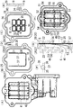
図2(B)(C)に示すように、板材(25)(26)にリード弁(17)の弁体(18)とその弁口(19)が設けられ、この板材(25)(26)の周縁部(27)(28)がEGR弁ケース(5)の弁ケースガス出口周縁部(22)とEGRガス導入通路(6)の導入通路ガス入口周縁部(23)とに挟み付けられるガスケット(29)(30)とされている。このため、リード弁(17)を省スペースで配置することができる。また、ガスケットの専用部品が不要になり、エンジンの部品点数を少なくすることができる。
図2(B)(C)に示すように、板材(25)(26)が、弁体(18)を備えた弁体付きの板材(25)と、弁口(19)を備えた弁口付きの板材(26)とで構成されている。このため、リード弁(17)を簡単かつ安価に製作することができる。
The configuration of the reed valve is as follows.
As shown in FIGS. 2 (B) and 2 (C), the plate member (25) (26) is provided with the valve element (18) of the reed valve (17) and its valve port (19), and this plate member (25) (26). ) Are sandwiched between the valve case gas outlet peripheral portion (22) of the EGR valve case (5) and the introduction passage gas inlet peripheral portion (23) of the EGR gas introduction passage (6).
As shown in FIGS. 2 (B) and 2 (C), the plate members (25) and (26) include a plate member (25) with a valve body including a valve body (18) and a valve port including a valve port (19). It is comprised with the board | plate material (26) with attached. For this reason, the reed valve (17) can be manufactured easily and inexpensively.
図2(D)に示すように、弁体付きの板材(25)と弁口付きの板材(26)の各周縁部(27)(28)のガスケット(29)(30)が、いずれもステップ形状のハーフビードとされている。このため、図2(G)に例示するように、EGR弁ケース(5)の弁ケースガス出口(10)とEGRガス導入通路(6)の導入通路ガス入口(11)との境界の接合箇所のガスケット(29)(30)の封止性が高い。
図2(B)に示すように、弁体付きの板材(25)は、その板材(25)に弁体(18)の外形に沿うスリット(31)が設けられ、このスリット(31)で囲まれた板材部分が弁体(18)とされ、弁口付きの板材(26)は、その板材(26)に弁口(19)が設けられ、弁口(19)の周縁部分の板材部分が弁座(32)とされている。このため、リード弁(17)を簡単かつ安価に製作することができる。
図2(C)(E)に示すように、弁口付きの板材(26)に複数の弁口(19)(19)が並設され、各弁口(19)の周縁部分がステップ状に形成され、その弁体側段差面(33)(34)のうち、弁体に近い方の面(33)が弁座(32)とされている。このため、弁座(32)の剛性が高く、リード弁閉弁時の封止性が高い。
As shown in FIG. 2 (D), the gaskets (29) and (30) of the peripheral portions (27) and (28) of the plate member (25) with a valve body and the plate member (26) with a valve port are both steps. The shape is a half bead. For this reason, as illustrated in FIG. 2 (G), the joint portion at the boundary between the valve case gas outlet (10) of the EGR valve case (5) and the introduction passage gas inlet (11) of the EGR gas introduction passage (6). The sealing properties of the gaskets (29) and (30) are high.
As shown in FIG. 2 (B), the plate member (25) with a valve element is provided with a slit (31) along the outer shape of the valve element (18) in the plate member (25), and is surrounded by the slit (31). The plate member portion is a valve body (18), and the plate member (26) with a valve opening is provided with a valve port (19) in the plate member (26), and the plate member portion at the peripheral portion of the valve port (19) is The valve seat (32) is used. For this reason, the reed valve (17) can be manufactured easily and inexpensively.
As shown in FIGS. 2 (C) and 2 (E), a plurality of valve ports (19) and (19) are arranged side by side on a plate (26) with valve ports, and the peripheral portions of the valve ports (19) are stepped. Of the formed valve body side step surfaces (33) and (34), the surface (33) closer to the valve body is the valve seat (32). For this reason, the rigidity of the valve seat (32) is high, and the sealing performance when the reed valve is closed is high.
図2(B)(C)に示すように、弁座(32)に常時開通口(35)が設けられ、弁口(19)から噴出するEGRガス(15)で弁体(18)が開弁する前に、この常時開通口(35)から噴出するEGRガス(15)で弁体周縁部(36)が開弁方向の圧を受けるようになっている。このため、弁体(18)の弁座(32)への貼り付きや弁体(18)の静止慣性等による弁体(18)の開弁遅れが防止される。
図2(F)に示すように、常時開通口(35)が円形に形成され、弁体周縁部(36)に常時開通口(35)と同心で常時開通口(35)よりも小径の円弧状の切欠き(37)が設けられ、常時開通口(35)から噴出するEGRガス(15)が円弧状の切欠き(37)の周縁部(38)に吹き当たるようにしている。このため、弁体(18)の開弁遅れ防止機能が高い。
その理由は、次のように推定される。
常時開通口(35)から噴出するEGRガス(15)のうち、最も流速が速い常時開通口(35)の中心部からの噴出ガスが切欠き(37)を通過し、流速が遅い常時開通口(35)の周縁部からの噴出ガスが円弧状の切欠き(37)の周縁部(38)に吹き当たるため、常時開通口(35)への噴出ガスの跳ね返りが緩やかで、弁体周縁部(36)付近でのEGRガス(15)の乱流の発生が抑制され、乱流による弁体(18)の振動が起こりにくく、振動による開弁遅れが防止され、弁体(18)の開弁遅れ防止機能が高い。
As shown in FIGS. 2B and 2C, the valve seat (32) is always provided with an opening (35), and the EGR gas (15) ejected from the valve opening (19) opens the valve body (18). Before the valve is operated, the valve body peripheral portion (36) receives pressure in the valve opening direction by the EGR gas (15) ejected from the normally open port (35). For this reason, the valve opening delay of the valve body (18) by the sticking of the valve body (18) to the valve seat (32), the stationary inertia of the valve body (18), etc. is prevented.
As shown in FIG. 2 (F), the normally open port (35) is formed in a circular shape, and the valve body peripheral portion (36) is concentric with the normally open port (35) and smaller in diameter than the normally open port (35). An arc-shaped notch (37) is provided so that the EGR gas (15) ejected from the normally open opening (35) is blown against the peripheral edge (38) of the arc-shaped notch (37). For this reason, the valve opening delay prevention function of the valve body (18) is high.
The reason is estimated as follows.
Of the EGR gas (15) ejected from the normally open port (35), the gas ejected from the center of the normally open port (35) having the fastest flow velocity passes through the notch (37), and the normally opened port has a slow flow rate. Since the gas ejected from the peripheral edge of (35) blows to the peripheral edge (38) of the arc-shaped cutout (37), the rebounding of the ejected gas to the always-opening opening (35) is gentle, and the valve body peripheral edge (36) The occurrence of turbulent flow of the EGR gas (15) in the vicinity is suppressed, the vibration of the valve body (18) due to turbulence is less likely to occur, the delay in valve opening due to vibration is prevented, and the opening of the valve body (18) is prevented. High valve delay prevention function.
図1(A)(B)に示すように、EGRガス導入通路(6)が前後方向に向けられた整流板(39)を備え、EGRガス(15)が整流板(39)に沿って後直進方向に整流されながら、吸気導入管(7)に案内されるようにしている。
図1(A)(B)に示すように、整流板(39)が、EGRガス導入通路(6)の上壁(40)から下向きに突出される複数枚の下向き整流板(41)と、EGRガス導入通路(6)の下壁(42)から上向きに突出される複数枚の上向き整流板(43)とで構成されている。
図1(B)に示すように、下向き整流板(41)で区分される上側区分通路(44)と上向き整流板(43)で区分される下側区分通路(45)とからなる各区分通路(46)が、上側区分通路(44)の下開口(47)と下側区分通路(45)の上開口(48)とを介して相互に連通されている。
図1(B)に示すように、下向き整流板(41)が下側区分通路(45)に向けて突出され、上向き整流板(43)が上側区分通路(44)に向けて突出されている。
As shown in FIGS. 1 (A) and 1 (B), the EGR gas introduction passage (6) includes a rectifying plate (39) oriented in the front-rear direction, and the EGR gas (15) is moved along the rectifying plate (39). While being straightened in the straight direction, it is guided to the intake air introduction pipe (7).
As shown in FIGS. 1A and 1B, a rectifying plate (39) includes a plurality of downward rectifying plates (41) protruding downward from the upper wall (40) of the EGR gas introduction passage (6); A plurality of upward rectifying plates (43) projecting upward from the lower wall (42) of the EGR gas introduction passage (6).
As shown in FIG. 1 (B), each divided passage comprising an upper divided passage (44) divided by a downward rectifying plate (41) and a lower divided passage (45) divided by an upward rectifying plate (43). (46) communicate with each other via the lower opening (47) of the upper section passage (44) and the upper opening (48) of the lower section passage (45).
As shown in FIG. 1 (B), the downward rectifying plate (41) protrudes toward the lower section passage (45), and the upward rectifying plate (43) protrudes toward the upper section passage (44). .
図2(G)に示すように、下向き整流板(41)の前方上側に延長部(49)が設けられ、この延長部(49)が弁体(18)の開弁ストッパー(50)及び弁体拘束部(51)とされ、弁体拘束部(51)は開弁ストッパー(50)の上側に配置され、弁体拘束部(51)とEGR弁ケース(5)の弁ケースガス出口(10)の上開口縁部(56)により、弁体(18)の基部(52)が挟み付けられ、この弁体(18)の基部(52)よりも下側の弁体部分(53)が撓んで開弁されるようにしている。このため、弁体(18)の基部(52)の微振動や弁体(18)の過剰な開弁によるリード弁(17)の損傷が抑制され、リード弁(17)の耐久性を高くすることができる。
図2(H)に示すように、延長部(49)の両横側縁(54)(54)が弁体(18)の両横側縁(55)(55)よりも内寄りに配置されている。このため、EGR率の低下が防止される。
その理由は、次のように推定される。
図2(H)に例示するように、延長部(49)の両横側縁(54)(54)が弁体(18)の両横側縁(55)(55)よりも内寄りに配置されているので、弁体(18)の両横側縁(55)(55)が開弁ストッパー(50)及び弁体拘束部(51)よりも後寄りになるまで、弁体(18)が捩れる余地があり、弁体(18)が受けるEGRガス(15)のガス圧分布が左右不均一であっても、弁体(18)が捩れながらスムーズに開弁し、EGR率の低下が防止される。
図2(G)に示すように、EGRガス導入通路(6)の導入通路ガス入口(11)内で、下側の弁体部分(53)の下方に固形分落下空間(57)が形成されている。このため、下側の弁体部分(53)に至ったカーボン等の固形分は、固形分落下空間(57)を介して下方に落下するため、リード弁(17)での固形分の噛み込みを防止することができる。
吸気分配通路壁(69)と吸気導入管(7)とEGRガス導入通路(6)の通路壁と下向き整流板(41)とその延長部(49)と上向き整流板(43)とは、一連の鋳造一体成型品である。
As shown in FIG. 2 (G), an extension part (49) is provided on the upper front side of the downward rectifying plate (41), and this extension part (49) serves as a valve opening stopper (50) and a valve of the valve body (18). The valve body restraining part (51) is disposed above the valve opening stopper (50), and the valve body gas outlet (10) of the valve body restraining part (51) and the EGR valve case (5) is provided. ) Is sandwiched by the upper opening edge portion (56), and the valve body portion (53) below the base portion (52) of the valve body (18) is bent. The valve is opened. For this reason, damage to the reed valve (17) due to slight vibration of the base (52) of the valve body (18) and excessive opening of the valve body (18) is suppressed, and durability of the reed valve (17) is increased. be able to.
As shown in FIG. 2 (H), both lateral edges (54) and (54) of the extension (49) are disposed inwardly of the lateral edges (55) and (55) of the valve element (18). ing. For this reason, the fall of an EGR rate is prevented.
The reason is estimated as follows.
As illustrated in FIG. 2 (H), both lateral edges (54) and (54) of the extension (49) are disposed more inward than the lateral edges (55) and (55) of the valve element (18). Therefore, the valve body (18) is moved until the both lateral edges (55) (55) of the valve body (18) are located rearward of the valve opening stopper (50) and the valve body restraining portion (51). Even if there is room for twisting and the gas pressure distribution of the EGR gas (15) received by the valve body (18) is not uniform left and right, the valve body (18) opens smoothly while twisting, and the EGR rate decreases. Is prevented.
As shown in FIG. 2 (G), a solid content falling space (57) is formed below the lower valve body portion (53) in the introduction passage gas inlet (11) of the EGR gas introduction passage (6). ing. For this reason, since the solid content such as carbon that has reached the lower valve body portion (53) falls downward through the solid content drop space (57), the solid content is caught in the reed valve (17). Can be prevented.
The intake distribution passage wall (69), the intake introduction pipe (7), the passage wall of the EGR gas introduction passage (6), the downward rectifying plate (41), its extension (49), and the upward rectifying plate (43) are a series of This is a cast integrated product.
EGRガスの冷却装置の構成は、次の通りである。
図5に示すように、シリンダヘッド(2)に水冷ジャケット内を通過するヘッド内EGR通路(80)が設けられている。シリンダヘッド(2)の横側面には吸気分配通路(3)の前で、接続管(94)が取り付けられ、ヘッド内EGR通路(80)から接続管(94)を介してEGRクーラ(4)にEGRガス(15)が導入されるようになっている。
図5に示すように、EGRクーラ(4)内にクーラジャケット(81)が形成され、EGR弁ケース(5)内に弁冷却水路(79)が形成され、このクーラジャケット(81)と弁冷却水路(79)とが冷却水中継パイプ(83)を介して直列接続されている。図6に示すように、クーラジャケット(81)のクーラジャケット入口(84)は、冷却水入口パイプ(85)を介してシリンダジャケット出口(86)と連通している。クーラジャケット(81)のクーラジャケット出口(87)は、冷却水中継パイプ(83)を介して弁冷却水路(82)の水路入口(88)に連通している。弁冷却水路(82)の水路出口(89)は、冷却水出口パイプ(90)を介して冷却水吸込み通路(図外)の通路入口(91)に連通している。冷却水吸込み通路の通路出口(図外)は、水ポンプ(63)の吸込み口(図外)と連通している。シリンダジャケット内の冷却水は、水ポンプ(63)の吸込み力により、シリンダジャケット出口(86)とクーラジャケット(81)と弁冷却水路(82)と冷却水出口パイプ(90)と冷却水吸込み通路とをその順に通過して水ポンプ(63)に吸い込まれ、他の冷却水と合流して、ラジエータ(図外)に圧送され、再度、シリンダジャケット内に戻る。
The configuration of the EGR gas cooling device is as follows.
As shown in FIG. 5, the cylinder head (2) is provided with an in-head EGR passage (80) that passes through the water-cooling jacket. A connecting pipe (94) is attached to the side surface of the cylinder head (2) in front of the intake distribution passage (3), and the EGR cooler (4) is connected to the EGR passage (80) in the head via the connecting pipe (94). The EGR gas (15) is introduced into the tank.
As shown in FIG. 5, a cooler jacket (81) is formed in the EGR cooler (4), a valve cooling water passage (79) is formed in the EGR valve case (5), and the cooler jacket (81) and the valve cooling are formed. The water channel (79) is connected in series via the cooling water relay pipe (83). As shown in FIG. 6, the cooler jacket inlet (84) of the cooler jacket (81) communicates with the cylinder jacket outlet (86) via the cooling water inlet pipe (85). The cooler jacket outlet (87) of the cooler jacket (81) communicates with the water channel inlet (88) of the valve cooling water channel (82) via the cooling water relay pipe (83). The water passage outlet (89) of the valve cooling water passage (82) communicates with the passage inlet (91) of the cooling water suction passage (not shown) via the cooling water outlet pipe (90). A passage outlet (not shown) of the cooling water suction passage communicates with a suction port (not shown) of the water pump (63). The cooling water in the cylinder jacket is cooled by the suction force of the water pump (63), the cylinder jacket outlet (86), the cooler jacket (81), the valve cooling water passage (82), the cooling water outlet pipe (90), and the cooling water suction passage. Are sequentially sucked into the water pump (63), merged with the other cooling water, pumped to the radiator (not shown), and returned to the cylinder jacket again.
図1(A)、図5に示すように、排気合流通路(67)からシリンダヘッド(2)外を通過するヘッド外EGR通路(92)が導出され、このヘッド外EGR通路(92)の下流にEGRクーラ(4)が配置され、EGRクーラ(4)にヘッド内EGR通路(80)とヘッド外EGR通路(92)の両方からEGRガスが導入されるようにしている。 As shown in FIGS. 1 (A) and 5, an out-head EGR passage (92) passing outside the cylinder head (2) is led out from the exhaust merging passage (67), and downstream of the out-head EGR passage (92). The EGR cooler (4) is disposed in the EGR cooler (4) so that EGR gas is introduced into the EGR cooler (4) from both the in-head EGR passage (80) and the outside-head EGR passage (92).
図6〜図8に示すように、エンジン冷却ファン(93)の後方にヘッド外EGR通路(92)が配置され、このヘッド外EGR通路(92)にエンジン冷却ファン(93)で起こしたエンジン冷却風が吹き当たるようにしている。図8に示すように、クランク軸(1)の架設方向と平行な向きに見た場合に、ヘッド外EGR通路(92)はエンジン冷却ファン(93)と重なる位置よりも僅かにずれているが、エンジン冷却風の吹き当たり領域は、エンジン冷却ファン(93)の外周の軌跡よりも拡がるため、エンジン冷却風はヘッド外EGR通路(92)に吹き当たる。 As shown in FIGS. 6 to 8, an EGR passage (92) outside the head is disposed behind the engine cooling fan (93), and the engine cooling caused by the engine cooling fan (93) is caused in the EGR passage outside the head (92). The wind blows. As shown in FIG. 8, when viewed in a direction parallel to the installation direction of the crankshaft (1), the EGR passage (92) outside the head is slightly shifted from the position overlapping the engine cooling fan (93). Since the engine cooling air blowing area is larger than the locus of the outer periphery of the engine cooling fan (93), the engine cooling air blows against the head outside EGR passage (92).
(2) シリンダヘッド
(3) 吸気分配通路
(5) EGR弁ケース
(6) EGRガス導入通路
(7) 吸気導入管
(10) 弁ケースガス出口
(11) 導入通路ガス入口
(12) 導入通路ガス出口
(13) EGRガス入口
(14) 吸気
(15) EGRガス
(16) 吸気ポート
(17) リード弁
(39) 整流板
(40) 上壁
(41) 下向き整流板
(42) 下壁
(43) 上向き整流板
(44) 上側区分通路
(45) 下側区分通路
(46) 各区分通路
(47) 下開口
(48) 上開口
(2) Cylinder head
(3) Intake distribution passage
(5) EGR valve case
(6) EGR gas introduction passage
(7) Intake inlet pipe
(10) Valve case gas outlet
(11) Inlet passage gas inlet
(12) Introduction passage gas outlet
(13) EGR gas inlet
(14) Inhalation
(15) EGR gas
(16) Intake port
(17) Reed valve
(39) Current plate
(40) Upper wall
(41) Downward current plate
(42) Lower wall
(43) Upward current plate
(44) Upper section passage
(45) Lower section passage
(46) Each section passage
(47) Lower opening
(48) Upper opening
Claims (3)
シリンダヘッド(2)の横側面に吸気分配通路(3)が設けられ、この吸気分配通路(3)の上方に前から順にEGR弁ケース(5)とEGRガス導入通路(6)と吸気導入管(7)とが配置され、EGR弁ケース(5)の弁ケースガス出口(10)にEGRガス導入通路(6)の導入通路ガス入口(11)が連通され、EGRガス導入通路(6)の導入通路ガス出口(12)が吸気導入管(7)の周壁前側で吸気導入管(7)内に連通され、
吸気導入管(7)の軸長方向に沿って導入される吸気(14)に吸気導入管(7)の周壁前側から流入するEGRガス(15)が混入され、このEGRガス(15)が混入された吸気(14)が吸気分配通路(3)で各気筒の吸気ポート(16)(16)に分配されるようにした、多気筒エンジンにおいて、
EGRガス導入通路(6)からEGR弁ケース(5)へのEGRガス(15)の逆流を阻止するリード弁(17)の下流で、EGRガス導入通路(6)が前後方向に向けられた整流板(39)を備え、EGRガス(15)が整流板(39)に沿って後直進方向に整流されながら、吸気導入管(7)に案内されるようにした、ことを特徴とする多気筒エンジン。 The installation direction of the crankshaft (1) is the front-rear direction, and the width direction of the cylinder head (2) perpendicular to the installation direction of the crankshaft (1) is the lateral direction.
An intake distribution passage (3) is provided on the lateral surface of the cylinder head (2), and an EGR valve case (5), an EGR gas introduction passage (6), and an intake introduction pipe are sequentially arranged above the intake distribution passage (3) from the front. (7) is disposed, the introduction gas inlet (11) of the EGR gas introduction passage (6) is communicated with the valve case gas outlet (10) of the EGR valve case (5), and the EGR gas introduction passage (6) The introduction passage gas outlet (12) communicates with the intake introduction pipe (7) on the front side of the peripheral wall of the intake introduction pipe (7).
EGR gas (15) flowing from the front side of the peripheral wall of the intake air introduction pipe (7) is mixed into the intake air (14) introduced along the axial length direction of the intake air introduction pipe (7), and this EGR gas (15) is mixed. In the multi-cylinder engine in which the intake air (14) is distributed to the intake ports (16) and (16) of each cylinder in the intake air distribution passage (3),
Rectification in which the EGR gas introduction passage (6) is directed in the front-rear direction downstream of the reed valve (17) for preventing the backflow of the EGR gas (15) from the EGR gas introduction passage (6) to the EGR valve case (5) A multi-cylinder having a plate (39), wherein the EGR gas (15) is guided to the intake air introduction pipe (7) while being rectified in the straight forward direction along the rectifying plate (39). engine.
整流板(39)が、EGRガス導入通路(6)の上壁(40)から下向きに突出される複数枚の下向き整流板(41)と、EGRガス導入通路(6)の下壁(42)から上向きに突出される複数枚の上向き整流板(43)とで構成され、
下向き整流板(41)で区分される上側区分通路(44)と上向き整流板(43)で区分される下側区分通路(45)とからなる各区分通路(46)が、上側区分通路(44)の下開口(47)と下側区分通路(45)の上開口(48)とを介して相互に連通されている、ことを特徴とする多気筒エンジン。 The multi-cylinder engine according to claim 1,
The rectifying plate (39) includes a plurality of downward rectifying plates (41) protruding downward from the upper wall (40) of the EGR gas introduction passage (6), and the lower wall (42) of the EGR gas introduction passage (6). And a plurality of upward rectifying plates (43) protruding upward from
Each section passage (46) comprising an upper section passage (44) sectioned by the downward rectifying plate (41) and a lower section passage (45) sectioned by the upward rectifying plate (43) is divided into an upper section passage (44). ) And a lower section passage (45) through an upper opening (48).
下向き整流板(41)が下側区分通路(45)に向けて突出され、上向き整流板(43)が上側区分通路(44)に向けて突出されている、ことを特徴とする多気筒エンジン。 The multi-cylinder engine according to claim 2,
A multi-cylinder engine characterized in that a downward rectifying plate (41) protrudes toward the lower section passage (45) and an upward rectifying plate (43) protrudes toward the upper section passage (44).
Priority Applications (1)
| Application Number | Priority Date | Filing Date | Title |
|---|---|---|---|
| JP2008249735A JP4977675B2 (en) | 2008-09-29 | 2008-09-29 | Multi-cylinder engine |
Applications Claiming Priority (1)
| Application Number | Priority Date | Filing Date | Title |
|---|---|---|---|
| JP2008249735A JP4977675B2 (en) | 2008-09-29 | 2008-09-29 | Multi-cylinder engine |
Publications (2)
| Publication Number | Publication Date |
|---|---|
| JP2010077945A true JP2010077945A (en) | 2010-04-08 |
| JP4977675B2 JP4977675B2 (en) | 2012-07-18 |
Family
ID=42208647
Family Applications (1)
| Application Number | Title | Priority Date | Filing Date |
|---|---|---|---|
| JP2008249735A Expired - Fee Related JP4977675B2 (en) | 2008-09-29 | 2008-09-29 | Multi-cylinder engine |
Country Status (1)
| Country | Link |
|---|---|
| JP (1) | JP4977675B2 (en) |
Cited By (1)
| Publication number | Priority date | Publication date | Assignee | Title |
|---|---|---|---|---|
| JP2015034526A (en) * | 2013-08-09 | 2015-02-19 | 株式会社クボタ | Intake manifold of multi-cylinder engine |
Citations (7)
| Publication number | Priority date | Publication date | Assignee | Title |
|---|---|---|---|---|
| JPS6090552U (en) * | 1983-11-29 | 1985-06-21 | 富士重工業株式会社 | Internal combustion engine EGR device |
| JPH1113500A (en) * | 1997-06-27 | 1999-01-19 | Nippon Soken Inc | Flow noise control system for throttle valve |
| JP2001020814A (en) * | 1999-07-06 | 2001-01-23 | Aisan Ind Co Ltd | Throttle body |
| JP2006023859A (en) * | 2004-07-06 | 2006-01-26 | Internatl Business Mach Corp <Ibm> | Automatic compression/reduction of latch |
| JP2007092597A (en) * | 2005-09-28 | 2007-04-12 | Kubota Corp | Engine |
| JP2007315315A (en) * | 2006-05-26 | 2007-12-06 | Nissan Diesel Motor Co Ltd | Multi-cylinder engine |
| JP2008075632A (en) * | 2006-09-25 | 2008-04-03 | Kubota Corp | Multi-cylinder engine |
-
2008
- 2008-09-29 JP JP2008249735A patent/JP4977675B2/en not_active Expired - Fee Related
Patent Citations (7)
| Publication number | Priority date | Publication date | Assignee | Title |
|---|---|---|---|---|
| JPS6090552U (en) * | 1983-11-29 | 1985-06-21 | 富士重工業株式会社 | Internal combustion engine EGR device |
| JPH1113500A (en) * | 1997-06-27 | 1999-01-19 | Nippon Soken Inc | Flow noise control system for throttle valve |
| JP2001020814A (en) * | 1999-07-06 | 2001-01-23 | Aisan Ind Co Ltd | Throttle body |
| JP2006023859A (en) * | 2004-07-06 | 2006-01-26 | Internatl Business Mach Corp <Ibm> | Automatic compression/reduction of latch |
| JP2007092597A (en) * | 2005-09-28 | 2007-04-12 | Kubota Corp | Engine |
| JP2007315315A (en) * | 2006-05-26 | 2007-12-06 | Nissan Diesel Motor Co Ltd | Multi-cylinder engine |
| JP2008075632A (en) * | 2006-09-25 | 2008-04-03 | Kubota Corp | Multi-cylinder engine |
Cited By (1)
| Publication number | Priority date | Publication date | Assignee | Title |
|---|---|---|---|---|
| JP2015034526A (en) * | 2013-08-09 | 2015-02-19 | 株式会社クボタ | Intake manifold of multi-cylinder engine |
Also Published As
| Publication number | Publication date |
|---|---|
| JP4977675B2 (en) | 2012-07-18 |
Similar Documents
| Publication | Publication Date | Title |
|---|---|---|
| JP5527486B2 (en) | Ventilation control device for internal combustion engine | |
| US10337398B2 (en) | Blowby gas treatment device for internal combustion engine with supercharger | |
| CN101198777B (en) | A cooler arrangement | |
| US20170370329A1 (en) | Vehicular egr cooler | |
| JP4972665B2 (en) | Multi-cylinder engine | |
| JP4654170B2 (en) | Multi-cylinder engine | |
| US11067043B2 (en) | Intake manifold | |
| JP6459498B2 (en) | Engine intake structure | |
| JP4977675B2 (en) | Multi-cylinder engine | |
| JP5143066B2 (en) | Multi-cylinder engine | |
| JP2008190337A (en) | Engine | |
| JP3392513B2 (en) | V-type engine exhaust recirculation system | |
| JP2007085301A (en) | Multicylinder engine | |
| JP4814188B2 (en) | engine | |
| JP6413746B2 (en) | Intercooler | |
| JP2007085302A (en) | Multicylinder engine | |
| KR20050070395A (en) | Intake air control system using vortex tube | |
| JP2014132163A (en) | Intercooler | |
| JP5027059B2 (en) | Exhaust gas recirculation device in internal combustion engine | |
| JP5477484B2 (en) | EGR diffusion unit | |
| EP3112655A1 (en) | Intake manifold | |
| JP5917987B2 (en) | EGR gas introduction structure | |
| JPH08260958A (en) | Cooling structure for vertically mounted engine for automobile | |
| JP2009019541A (en) | Engine | |
| JP2017106339A (en) | Intake manifold |
Legal Events
| Date | Code | Title | Description |
|---|---|---|---|
| A621 | Written request for application examination |
Free format text: JAPANESE INTERMEDIATE CODE: A621 Effective date: 20100927 |
|
| A977 | Report on retrieval |
Free format text: JAPANESE INTERMEDIATE CODE: A971007 Effective date: 20111020 |
|
| A131 | Notification of reasons for refusal |
Free format text: JAPANESE INTERMEDIATE CODE: A131 Effective date: 20111025 |
|
| A521 | Written amendment |
Free format text: JAPANESE INTERMEDIATE CODE: A523 Effective date: 20111125 |
|
| TRDD | Decision of grant or rejection written | ||
| A01 | Written decision to grant a patent or to grant a registration (utility model) |
Free format text: JAPANESE INTERMEDIATE CODE: A01 Effective date: 20120410 |
|
| A01 | Written decision to grant a patent or to grant a registration (utility model) |
Free format text: JAPANESE INTERMEDIATE CODE: A01 |
|
| A61 | First payment of annual fees (during grant procedure) |
Free format text: JAPANESE INTERMEDIATE CODE: A61 Effective date: 20120416 |
|
| R150 | Certificate of patent or registration of utility model |
Ref document number: 4977675 Country of ref document: JP Free format text: JAPANESE INTERMEDIATE CODE: R150 Free format text: JAPANESE INTERMEDIATE CODE: R150 |
|
| FPAY | Renewal fee payment (event date is renewal date of database) |
Free format text: PAYMENT UNTIL: 20150420 Year of fee payment: 3 |
|
| LAPS | Cancellation because of no payment of annual fees |